1
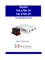
Model
TLB 6700-LN
TLB 6700-XP
Tunable Diode Laser
User’s Manual
EU Declaration of Conformity
We declare that the accompanying product, identified with the
mark,
complies with requirements of the Electromagnetic Compatibility Directive,
2004/108/EC and the Low Voltage Directive 2006/95/EC.
Model Numbers: TLB 6700-LN, TLB 6700-XP
Year
mark affixed: 2010
Type of Equipment: Electrical equipment for measurement, control and
laboratory use in industrial locations.
Manufacturer: Newport Corporation
1791 Deere Avenue
Irvine, CA 92606
Standards Applied:
Compliance was demonstrated to the following standards to the extent
applicable:
BS EN61326-1: 2006 “Electrical equipment for measurement, control and
laboratory use – EMC requirements” for use in a controlled electromagnetic
environment.
This equipment meets the CISPR 11:2009+A1 Class A Group 1 radiated and
conducted emission limits.
BS EN 61010-1:2010, “Safety requirements for electrical equipment for
measurement, control and laboratory use”.
Mark Carroll
Sr. Director, Instruments Business
Newport Corporation
1791 Deere Ave, Irvine, CA92606 USA
ii
Preface
Warranty
New Focus warrants that this product will be free from defects in material
and workmanship and will comply with Newport’s published specifications
at the time of sale for a period of one year from date of shipment. If found to
be defective during the warranty period, the product will either be repaired or
replaced at Newport's option.
To exercise this warranty, write or call your local Newport office or
representative, or contact Newport headquarters in Irvine, California. You
will be given prompt assistance and return instructions. Send the product,
freight prepaid, to the indicated service facility. Repairs will be made and the
instrument returned freight prepaid. Repaired products are warranted for the
remainder of the original warranty period or 90 days, whichever occurs first.
Limitation of Warranty
The above warranties do not apply to products, which have been repaired or
modified without Newport’s written approval, or products subjected to
unusual physical, thermal or electrical stress, improper installation, misuse,
abuse, accident or negligence in use, storage, transportation or handling. This
warranty also does not apply to fuses, batteries, or damage from battery
leakage.
THIS WARRANTY IS IN LIEU OF ALL OTHER WARRANTIES,
EXPRESSED OR IMPLIED, INCLUDING ANY IMPLIED WARRANTY
OF MERCHANTABILITY OR FITNESS FOR A PARTICULAR USE.
NEW FOCUS SHALL NOT BE LIABLE FOR ANY INDIRECT, SPECIAL,
OR CONSEQUENTIAL DAMAGES RESULTING FROM THE
PURCHASE OR USE OF ITS PRODUCTS.
First printing 2010
© 2010 by New Focus, Santa Clara, CA. All rights reserved. No part of this
manual may be reproduced or copied without the prior written approval of
New Focus.
This manual has been provided for information only and product
specifications are subject to change without notice. Any change will be
reflected in future printings.
New Focus
3635 Peterson Way
Santa Clara, CA, 95054
USA
Part No. 90038357 Rev D
Preface
iii
Confidentiality & Proprietary Rights
Reservation of Title
The New Focus programs and all materials furnished or produced in
connection with them ("Related Materials") contain trade secrets of New
Focus and are for use only in the manner expressly permitted. New Focus
claims and reserves all rights and benefits afforded under law in the Programs
provided by New Focus.
New Focus shall retain full ownership of Intellectual Property Rights in and
to all development, process, align or assembly technologies developed and
other derivative work that may be developed by New Focus. Customer shall
not challenge, or cause any third party to challenge the rights of New Focus.
Preservation of Secrecy and Confidentiality and Restrictions to Access
Customer shall protect the New Focus Programs and Related Materials as
trade secrets of New Focus, and shall devote its best efforts to ensure that all
its personnel protect the New Focus Programs as trade secrets of New Focus.
Customer shall not at any time disclose New Focus's trade secrets to any
other person, firm, organization, or employee that does not need (consistent
with Customer's right of use hereunder) to obtain access to the New Focus
Programs and Related Materials. These restrictions shall not apply to
information (1) generally known to the public or obtainable from public
sources; (2) readily apparent from the keyboard operations, visual display, or
output reports of the Programs; 3) previously in the possession of Customer
or subsequently developed or acquired without reliance on the New Focus
Programs; or (4) approved by New Focus for release without restriction.
Trademarks
The New Focus logo and name are registered trademarks of Newport
Corporation in Mexico, Israel, Singapore, European Union, Taiwan, Hong
Kong, China, Japan, Korea, Canada, Australia, and the United States.
Service Information
This section contains information regarding factory service for the source.
The user should not attempt any maintenance or service of the system or
optional equipment beyond the procedures outlined in this manual. Any
problem that cannot be resolved should be referred to New Focus.
iv
Preface
Technical Support Contacts
North America
Europe
New Focus
3635 Peterson Way, Santa Clara, CA 95054
Telephone: (866) 683-6287
Telephone: (408) 919-1500
Newport/MICRO-CONTROLE S.A.
Zone Industrielle
45340 Beaune la Rolande, FRANCE
Telephone: (33) 02 38 40 51 56
Asia
Newport Opto-Electronics Technologies
中国 上海市 爱都路 253号 第3号楼 3层
C部位, 邮编 200131
253 Aidu Road, Bld #3, Flr 3, Sec C,
Shanghai 200131, China
Telephone: +86-21-5046 2300
Fax: +86-21-5046 2323
Newport Corporation Calling Procedure
If there are any defects in material or workmanship or a failure to meet
specifications, promptly notify Newport's Returns Department by calling 1-800-2226440 or by visiting our website at www.newport.com/returns within the warranty
period to obtain a Return Material Authorization Number (RMA#). Return the
product to Newport Corporation, freight prepaid, clearly marked with the RMA# and
we will either repair or replace it at our discretion. Newport is not responsible for
damage occurring in transit and is not obligated to accept products returned without
an RMA#.
E-mail: [email protected]
When calling Newport Corporation, please provide the customer care representative
with the following information:
Your Contact Information
Serial number or original order number
Description of problem (i.e., hardware or software)
To help our Technical Support Representatives diagnose your problem, please note
the following conditions:
Is the system used for manufacturing or research and development?
What was the state of the system right before the problem?
Have you seen this problem before? If so, how often?
Can the system continue to operate with this problem? Or is the system nonoperational?
Can you identify anything that was different before this problem occurred?
Preface
v
Table of Contents
EU Declaration of Conformity ................................................................ i
Warranty................................................................................................. ii
Technical Support Contacts .................................................................. iv
Table of Contents ................................................................................... v
List of Figures ....................................................................................... ix
List of Tables......................................................................................... ix
1
Safety Precautions
1.1
1.2
1.3
2
2.2
2.3
3
Definitions and Symbols ............................................................ 11
1.1.1 General Warning or Caution ...........................................11
1.1.2 Electric Shock ..................................................................11
1.1.3 European Union CE Mark ...............................................11
1.1.4 Alternating Voltage Symbol ............................................12
1.1.5 On ....................................................................................12
1.1.6 Off....................................................................................12
1.1.7 Fuses ................................................................................12
1.1.8 USB .................................................................................13
1.1.9 Frame or Chassis .............................................................13
1.1.10 Waste Electrical and Electronic Equipment (WEEE) .....13
1.1.11 Control of Hazardous Substances ....................................14
Warnings and Cautions............................................................... 14
1.2.1 General Warnings ............................................................14
1.2.2 General Cautions .............................................................15
1.2.3 Summary of Warnings and Cautions ...............................16
Location of Labels and Warnings............................................... 18
1.3.1 Rear Panel ........................................................................18
General Information
2.1
19
Introduction ................................................................................ 19
2.1.1 Instrument Features .........................................................20
Input Power ................................................................................ 20
Specifications ............................................................................. 21
2.3.1 Tunable Diode Laser .......................................................21
2.3.2 General Specifications .....................................................22
Getting Started
3.1
11
23
Unpacking and Handling ............................................................ 23
vi
Preface
3.2
3.3
3.4
3.5
3.6
3.7
4
Inspection for Damage ............................................................... 23
Parts List ..................................................................................... 24
Choosing and Preparing a Suitable Work Surface ..................... 24
Electrical Requirements.............................................................. 24
Power Supplies ........................................................................... 25
Quick Start .................................................................................. 26
3.7.1 Connecting the Laser Components ..................................26
3.7.2 Grounding and Powering the Laser System ....................27
3.7.3 Turning the Laser ON ......................................................27
3.7.4 Turning the Laser OFF ....................................................28
3.7.5 Software Installation ........................................................28
System Operation
4.1
29
Description of Laser System ...................................................... 29
4.1.1 Controller .........................................................................29
4.1.2 Laser Head .......................................................................30
4.2 Using the Front Panel ................................................................. 32
4.3 Setting Current / Power .............................................................. 33
4.4 Setting Wavelength .................................................................... 33
4.5 Fine Wavelength Control ........................................................... 33
4.6 Wavelength Track Mode ............................................................ 34
4.7 Setting Wavelength Scan Parameters ......................................... 34
4.7.1 Setting the Start and Stop Wavelengths ..........................34
4.7.2 Setting the Scan Velocity ................................................34
4.7.3 Performing a Scan ...........................................................34
4.7.4 Stopping a Scan ...............................................................35
4.8 Laser Power Display................................................................... 35
4.9 Wavelength Display ................................................................... 35
4.10 Menu Section .............................................................................. 35
4.10.1 Control Knob ...................................................................35
4.10.2 Setup / Enter ....................................................................35
4.10.3 Esc ...................................................................................36
4.10.4 Cursor Arrow Keys..........................................................36
4.10.5 Display Elements .............................................................36
4.10.6 Menu Selection ................................................................36
4.10.7 Title Screen ......................................................................37
4.10.8 Laser Head Information Screen .......................................37
4.10.9 Main Setup Screen ...........................................................38
4.10.10 Parameter Setup Screens .............................................38
Preface
vii
4.11 Rear Panel ................................................................................... 43
4.11.1 USB Interface ..................................................................43
4.11.2 Chassis GND ...................................................................43
4.11.3 AC Power ........................................................................43
4.11.4 Fuses ................................................................................44
4.11.5 Frequency Modulation Input ...........................................44
4.11.6 Current Modulation Input ................................................45
4.11.7 Wavelength Output ..........................................................45
4.11.8 Wavelength Input ............................................................46
4.11.9 Auxiliary Input ................................................................46
4.12 Constant Power Mode ................................................................ 47
5
Computer Interfacing
5.1
5.2
5.3
5.4
5.5
5.6
6
7
83
Introduction ................................................................................ 83
Grounding a Laser Head ............................................................. 83
Maintenance and Service
8.1
79
Theory of Design ........................................................................ 79
6.1.1 References .......................................................................82
Tips and Techniques
7.1
7.2
8
Introduction ................................................................................ 49
Computer Interface Terminology ............................................... 49
5.2.1 <…> Delimiting Punctuation ..........................................49
5.2.2 <CR> Carriage Return .....................................................49
5.2.3 <LF> Line Feed ...............................................................49
5.2.4 (;) Semicolons ..................................................................50
5.2.5 Command Termination ....................................................50
5.2.6 Response Termination .....................................................50
Controller Operation Mode ........................................................ 50
USB Communication.................................................................. 50
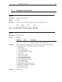
Commands Summary ................................................................. 51
5.5.1 Conventions .....................................................................51
5.5.2 Types of Commands ........................................................51
5.5.3 Index of Commands ........................................................53
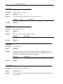
Commands and Queries .............................................................. 55
Principles of Operation
6.1
49
85
Enclosure Cleaning ..................................................................... 85
viii
Preface
8.2
8.3
8.4
8.5
8.6
9
Technical Support ....................................................................... 85
Service ........................................................................................ 86
Obtaining Service ....................................................................... 86
Warranty ..................................................................................... 86
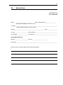
Service Form .............................................................................. 87
Appendix A – Error Messages
9.1
9.2
89
Introduction ................................................................................ 89
Error Description ........................................................................ 89
Preface
ix
List of Figures
Figure 1
Figure 2
Figure 3
Figure 4
Figure 5
Figure 6
Figure 7
Figure 8
Figure 9
Figure 10
Figure 11
Figure 12
Figure 13
Figure 14
Figure 15
Figure 16
Figure 17
Figure 18
Figure 19
Figure 20
Figure 21
Figure 22
Figure 23
Figure 24
Figure 25
Figure 26
Figure 27
Figure 28
General Warning or Caution Symbol ..........................................11
Electrical Shock Symbol .............................................................11
CE Mark ......................................................................................11
Alternating Voltage Symbol ........................................................12
On Symbol ...................................................................................12
Off Symbol ..................................................................................12
Fuse Symbol ................................................................................12
USB Symbol ................................................................................13
Frame or Chassis Terminal Symbol ............................................13
WEEE Directive Symbol .............................................................13
RoHS Compliant Symbol ............................................................14
Rear Panel Labels and Warnings .................................................18
Controller Block Diagram ...........................................................29
Laser Head Mechanical Schematic forTLB-6700 series laser ....31
Front Panel Layout ......................................................................32
A Sample Setup Screen ...............................................................36
A Sample Title Screen .................................................................37
A Sample Laser Head Information Screen ..................................37
A Sample LDD and TEC Params Measurement Screen .............38
Model 6700 Menu Structure ........................................................39
A Sample System Parameters Sub-menu ....................................40
A Sample Save Parameters Sub-menu ........................................41
A Sample Save Parameters Sub-menu ........................................41
A Sample Main Setup Screen when Errors Present ....................42
A Sample Setup Screen when Errors Present ..............................42
Rear Panel ....................................................................................43
New Focus Laser Cavity .............................................................80
Drawing of Important Angles and Optimal Pivot Point ..............81
List of Tables
Table 1
Voltage Selector Switch Settings and Fuse Ratings ....................25
x
Preface
This page is intentionally left blank
1
1.1
Safety Precautions
Definitions and Symbols
The following terms and symbols are used in this documentation and appear
on the Model 6700 Tunable Diode Laser where safety-related issues occur.
1.1.1
General Warning or Caution
Figure 1
General Warning or Caution Symbol
The Exclamation Symbol in the figure above appears on the product and in
Warning and Caution tables throughout this document. This symbol
designates that documentation needs to be consulted to determine the nature
of a potential hazard, and any actions that have to be taken.
1.1.2
Electric Shock
Figure 2
Electrical Shock Symbol
The Electrical Shock Symbol in the figure above appears throughout this
manual. This symbol indicates a hazard arising from dangerous voltage.
Any mishandling could result in irreparable damage to the equipment, and
personal injury or death.
1.1.3
European Union CE Mark
Figure 3
CE Mark
12
Safety Precautions
The presence of the CE Mark on Newport Corporation equipment means that
this instrument has been designed, tested and certified compliant to all
applicable European Union (CE) regulations and recommendations.
1.1.4
Alternating Voltage Symbol
Figure 4
~
Alternating Voltage Symbol
This international symbol implies an alternating voltage or current.
1.1.5
On
I
Figure 5
On Symbol
The symbol in the figure above represents a power switch position on the
Model 6700 Tunable Diode Laser. This symbol represents a Power On
condition.
1.1.6
Off
Figure 6
Off Symbol
The symbol in the figure above represents a power switch position on the
Model 6700 Tunable Diode Laser. This symbol represents a Power Off
condition.
1.1.7
Fuses
Figure 7
Fuse Symbol
The symbol in the figure above identifies the fuse location on the Model 6700
Tunable Diode Laser.
Safety Precautions
1.1.8
13
USB
Figure 8
USB Symbol
The symbol in the figure above identifies the USB connector location on the
Model 6700 Tunable Diode Laser.
1.1.9
Frame or Chassis
Figure 9
Frame or Chassis Terminal Symbol
The symbol in the figure above appears on the Model 6700 Tunable Diode
Laser. This symbol identifies the frame or chassis terminal
1.1.10
Waste Electrical and Electronic Equipment (WEEE)
Figure 10
WEEE Directive Symbol
This symbol on the product or on its packaging indicates that this product
must not be disposed with regular waste. Instead, it is the user responsibility
to dispose of waste equipment according to the local laws. The separate
collection and recycling of the waste equipment at the time of disposal will
help to conserve natural resources and ensure that it is recycled in a manner
that protects human health and the environment. For information about
where the user can drop off the waste equipment for recycling, please contact
your local Newport Corporation representative.
14
Safety Precautions
1.1.11
Control of Hazardous Substances
Figure 11
RoHS Compliant Symbol
This label indicates the products comply with the EU Directive 2002/95/EC
that restricts the content of six hazardous chemicals.
1.2
Warnings and Cautions
The following are definitions of the Warnings, Cautions and Notes that are
used throughout this manual to call your attention to important information
regarding your safety, the safety and preservation of your equipment or an
important tip.
WARNING
Situation has the potential to cause bodily harm or death.
CAUTION
Situation has the potential to cause damage to property or
equipment.
NOTE
Additional information the user or operator should consider.
1.2.1
General Warnings
Observe these general warnings when operating or servicing this equipment:
Heed all warnings on the unit and in the operating instructions.
Do not use this equipment in or near water.
This equipment is grounded through the grounding conductor of the
power cord.
Safety Precautions
15
Route power cords and other cables so that they are not likely to be
1.2.2
damaged.
Disconnect power before cleaning the equipment. Do not use liquid or
aerosol cleaners; use only a damp lint-free cloth.
Lockout all electrical power sources before servicing the equipment.
To avoid fire hazard, use only the specified fuse(s) with the correct type
number, voltage and current ratings as referenced in the appropriate
locations in the service instructions or on the equipment. Only qualified
service personnel should replace fuses.
To avoid explosion, do not operate this equipment in an explosive
atmosphere.
Qualified service personnel should perform safety checks after any
service.
General Cautions
Observe these cautions when operating this equipment:
If this equipment is used in a manner not specified in this manual, the
protection provided by this equipment may be impaired.
To prevent damage to equipment when replacing fuses, locate and correct
the problem that caused the fuse to blow before re-applying power.
Do not block ventilation openings.
Do not position this product in such a manner that would make it difficult
to disconnect the power cord.
Position the equipment so that access to the mains disconnect On/Off
switch is readily available.
Use only the specified replacement parts.
Follow precautions for static sensitive devices when handling this
equipment.
This product should only be powered as described in the manual.
There are no user-serviceable parts inside the Model 6700 Tunable Diode
Laser.
Adhere to good laser safety practices when using this equipment.
16
Safety Precautions
1.2.3
Summary of Warnings and Cautions
The following general warning and cautions are applicable to this instrument:
WARNING
Before operating the Model 6700 Tunable Diode Laser, please
read and understand all of Section 1.
WARNING
Do not attempt to operate this equipment if there is evidence of
shipping damage or you suspect the unit is damaged. Damaged
equipment may present additional hazards to you. Contact
Newport technical support for advice before attempting to plug
in and operate damaged equipment.
WARNING
To avoid electric shock, connect the instrument to properly
earth-grounded, 3-prong receptacles only. Failure to observe
this precaution can result in severe injury.
WARNING
Before cleaning the enclosure of the Model 6700 Tunable Diode
Laser, the AC power cord must be disconnected from the wall
socket.
CAUTION
There are no user serviceable parts inside the Model 6700
Tunable Diode Laser. Work performed by persons not
authorized by Newport Corporation will void the warranty. For
instructions on obtaining warranty repair or service, please refer
to Section 8.
WARNING
If this equipment is used in a manner not specified in this
manual, the protection provided by this equipment may be
impaired.
Safety Precautions
17
WARNING
While the Model TLB-6700 Controller’s rear panel switch turns
power OFF to the internal electronics, it should not be depended
upon to fully disconnect the unit from MAINS power. Disconnect
the power cord to fully isolate the Model 6700 from MAINS
power.
WARNING
The rear panel LASER CONTROL connector may have voltages
as high as 150 VDC between various connector pins. Do not
power up the Model 6700 without a laser head connected.
WARNING
Do not attempt to power up the controller if the cable between
the controller and the laser head is damaged.
WARNING
Use only New Focus Model Number TLB-6700-01 cable, or New
Focus approved alternative, to connect the TLB-6700 controller
to the 6700 series laser head.
WARNING
Do not disconnect the cable between the Model 6700 and the
laser head from the Model 6700 while the Model 6700 is powered
up.
WARNING
Do not disconnect the cable between the Model 6700 and the
laser head from the laser head while the Model 6700 is powered
up.
WARNING
Secure the connector screwlocks at both ends of the cable
between the Model 6700 and the laser head.
18
Safety Precautions
The Model TLB-6700 Controller is intended for use in an
industrial environment. Use of this product in other
environments, such as residential, may result in electromagnetic
compatibility difficulties due to conducted as well as radiated
disturbances.
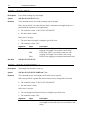
1.3
Location of Labels and Warnings
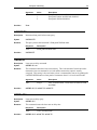
1.3.1
Rear Panel
Fuse Label
Model,
Serial
Number and
WEEE
Symbol
RoHS Label
CE Label
Figure 12
Max
Power
Label
Rear Panel Labels and Warnings
2
2.1
General Information
Introduction
The New Focus 6700 series External Cavity Tunable Diode Laser is a stable,
narrow-linewidth source of tunable light. The 6700 series laser can be
operated manually from the front panel of the controller or remotely using
computer control.
The 6700 series laser incorporates a simple, stable mechanical design with a
minimal number of optical components. Low-noise analog circuits precisely
set critical operating parameters, such as diode temperature and current.
Digital control facilitates remote operation and computer interfacing.
The 6700 is a modular system. The same control unit will work with any
6700 series laser head. The control units work in both manual and remotely
programmed modes and are compatible with USB interfaces.
Digital Signal Processor (DSP)-based motion control allows you hands-free
wavelength-scanning capability. You set the start and stop wavelengths and
scanning speed and the microprocessor-controlled DC motor takes care of the
rest. The unique cavity design enables continuous mode hop-free tuning.
Two seven segment LED digital readouts and a multi-line LCD display show
important operating parameters including wavelength and laser power. Inputs
are available for low-speed and high-speed diode current modulation.
Key Product Features:
Versatile tuning performance
• Sweep, step, and fine-tuning modes
• Fine-tuning with the PZT at 0.1-GHz resolution
• Coarse-tuning with the DC motor for up to 80-nm mode hop-free tuning
• Smooth, linear, mode hop-free sweeps
20
General Information
Low noise & narrow linewidths
• <200-kHz linewidths
• >40-dB side-mode suppression ratios
Flexible configurations
• Wavelengths from 630 nm to 2 µm
• Fiber-coupled and free-space outputs
• Current modulation, wavelength control and FM modulation
• Constant power and constant current modes
Plug & play
• Automated wavelength scans with wavelength and power readouts
• USB remote interface
• No beam walking
2.1.1
Instrument Features
Intuitive Controls and LCD Display
Improved data presentation and system control are achieved using a
combination of LCD and 7-segment LED displays. The LCD display shows
the entire system configuration and status. The 7-segment LED displays
visibly show diode laser wavelength and output power. “Menu Keys” guide
you through initial system setup routines and operation. Real-time control of
an output is accomplished either by entering the set point via the cursor keys
or control knob. SETUP/ENTER and ARROW keys access saved system
configurations and repetitive procedures. All controls are clearly marked and
instructions easily understood for simple operation.
2.2
Input Power
The Model 6700 can be configured to operate on 100, 120, 220, or 240 volt
AC power. See Section 3.6 for information on how to configure the Model
6700 for operation on your country-specific AC voltage.
General Information
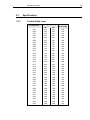
2.3
2.3.1
21
Specifications
Tunable Diode Laser
Tuning Range [nm]
Model Number
6701
6702
6703
6704
6705
6706
6707
6708
6709
6710
6711
6712
6713
6714
6715
6716
6717
6718
6719
6720
6721
6722
6723
6724
6725
6726
6727
6728
6729
6730
6731
6732
6733
6734
6735
Min
Max
350
390
440
630
640
650
680
650
715
700
700
760
750
750
750
800
800
850
900
900
900
1000
1100
1200
1300
1400
1350
1400
1400
1400
1550
1600
1700
1900
1900
400
440
500
640
650
680
700
750
750
800
800
800
850
850
900
950
950
1000
1100
1100
1100
1200
1300
1400
1500
1600
1600
1700
1700
1700
1750
1900
2200
2300
2500
Maximum
Power [mW]
450
450
450
450
450
450
450
450
450
450
450
450
450
450
450
450
450
450
450
450
450
450
450
450
450
450
450
450
450
450
450
450
450
450
450
22
General Information
2.3.2
General Specifications
Environmental Specifications
Voltage Requirements
Power Requirements
Chassis Ground
Size (H x W x D) [in. (mm)]
Mainframe Weight [lb (kg)]
Operating Temperature
100/120/220/240 VAC, 50/60Hz
MAX POWER = 170 Watts
4 mm banana jack
3.48 (88.4) x 14.0 (355.6) x 16.51 (419.4)
17.9 (8.1)
10ºC to 40ºC
(<90% humidity non-condensing)
Storage Temperature
0ºC to + 50ºC
(<90% humidity non-condensing)
Relative Humidity, Storage
Altitude
<90% humidity non-condensing
<3000 meters (10000 feet)
Installation Category
Pollution Degree
Use Location
II
2
Indoor use only
The Model 6700 Tunable Diode Laser is designed to operate in a controlled
electromagnetic environment. While it will not be damaged by operation in
an industrial electromagnetic environment, as defined in EN61316-1:2006,
such operation may not yield optimal performance. For this reason, New
Focus does not recommend operation of the Model 6700 in close proximity
to mobile telephones, hand-held radio transmitters, and similar devices.
3
3.1
Getting Started
Unpacking and Handling
It is recommended that the Model 6700 Tunable Diode Laser be unpacked in
a lab environment or work site. Unpack the system carefully; small parts are
included with the instrument. Inspect the box carefully for loose parts. You
are advised to save the packaging material in case you need to ship your
equipment in the future.
3.2
Inspection for Damage
The Model 6700 Tunable Diode Laser is carefully packaged at the factory to
minimize the possibility of damage during shipping. Inspect the box for
external signs of damage or mishandling. Inspect the contents for damage. If
there is visible damage to the instrument upon receipt, inform the shipping
company and New Focus immediately. Carefully open the box and save the
shipping material for later use.
WARNING
Do not attempt to operate this equipment if there is evidence of
shipping damage or you suspect the unit is damaged. Damaged
equipment may present additional hazards to you. Contact New
Focus technical support for advice before attempting to plug in
and operate damaged equipment.
CAUTION
The user is advised to save the packaging material in case the
unit has to be shipped to a different location. The packaging
material is specially designed to protect the unit during
shipping.
24
Getting Started
3.3
Parts List
The following is a list of parts included with the Model 6700 Tunable Diode
Laser:
1. CD with Software Drivers and Utilities, User’s Manual, Start Up Guide.
2. IEC320 AC line cord with a NEMA 5-15P, or country-specific
connector.
3. Cable for controlling unit and laser head connection, TLB-6700-01.
4. USB Cable for connecting the controller to a computer.
5. Spare fuses for 220 VAC, 230 VAC, and 240 VAC mains power.
If you are missing any parts or have questions about the parts you have
received, please contact New Focus.
3.4
Choosing and Preparing a Suitable Work Surface
The Model 6700 Tunable Diode Laser may be placed on any reasonably firm
table or bench during operation.
3.5
Electrical Requirements
Before attempting to power up the unit for the first time, the following
precautions must be followed:
WARNING
To avoid electric shock, connect the instrument to properly
earth-grounded, 3-prong receptacles only. Failure to observe
this precaution can result in severe injury.
Have a qualified electrician verify the wall socket that will be used is
properly polarized and properly grounded.
Provide adequate distance between the Models 6700 Tunable Diode
Laser and adjacent walls for ventilation purposes. Do not let any other
equipment blow hot air towards the Tunable Diode Laser. Verify the
correct rated fuses are installed according to the fuse marking on the rear
panel. The unit has temperature sensors. If the unit overheats it will
generate an error message and stop operation to protect itself, until the
user takes the necessary steps to lower the temperature.
Getting Started
3.6
25
Power Supplies
WARNING
To avoid electric shock, the Model 6700 must be configured for
operation on your specific AC line voltage PRIOR TO
CONNECTING THE POWER CORD TO THE AC MAINS. See the
instructions above for information
AC power is supplied through the rear panel power entry module connector
that provides in-line transient protection and RF filtering. The power entry
module also contains the instrument’s fuses and the voltage selection switch.
Prior to plugging in the AC line cord, the user MUST configure the Model
6700 for operation on the available AC power. This is accomplished by
setting the voltage selector switch on the AC power entry module AND
verifying that the correct fuses are installed into the power entry module.
Failure to do this can result in degraded instrument performance, damage to
the Model 6700, and / or injury to the operator.
The voltage selector switch and the fuses are accessed by opening the power
entry module using a flat-bladed screwdriver. Note that the AC line cord
must be removed from the power entry module prior to attempting to open it.
With the power entry module open, the voltage selector switch setting can be
changed by removing the drum, rotating it to the desired setting, and
reinstalling the drum. Do not attempt to rotate the drum, while it is inserted
in the power entry module. You risk bending the power contacts and render
the unit inoperable.
After correctly setting the voltage selection switch, the fuses installed in the
power entry module should be checked for the correct value and, if not
correct, changed.
Table 1, below, identifies the correct voltage selector switch setting and fuse
ratings for several common AC power.
Input Power
100 VAC, 50 Hz
120 VAC, 60 Hz
220 VAC, 50 Hz
230 VAC, 50 Hz
240 VAC, 60 Hz
Table 1
Voltage Switch Setting
100
120
230
230
240
Fuses
2A, 250VAC, Slo-Blo
2A, 250VAC, Slo-Blo
1A, 250VAC, Slo-Blo
1A, 250VAC, Slo-Blo
1A, 250VAC, Slo-Blo
Voltage Selector Switch Settings and Fuse Ratings
26
Getting Started
WARNING
With the power entry module open, the voltage selector switch
setting can be changed by removing the drum, rotating it to the
desired setting, and reinstalling the drum. Do not attempt to
rotate the drum, while it is inserted in the power entry module.
Failure to observe this procedure will result in equipment
damage.
WARNING
To avoid electric shock, connect the instrument to properly
earth-grounded receptacles only. Failure to observe these
precautions can result in fire, severe injury or death.
WARNING
To avoid electric shock, the appropriate fuses for the AC input
power voltage must be installed in the instrument. Only
qualified service personnel should replace fuses. Failure to
observe these precautions can result in fire, severe injury or
death.
3.7
Quick Start
This section outlines the basic steps needed to start using your 6700 Series
External Cavity Tunable Diode Laser, including a brief setup and getting
started guide. It assumes that earlier sections regarding safety and AC input
power settings have been read. For more detailed information on how to
operate the instrument, refer to Chapter 4 System Operation.
3.7.1
Connecting the Laser Components
Connect the Model TLB-6700 Controller to the 6700 series laser head using
the TLB-6700-01 or other approved New Focus Cable. Secure the screw
locks on the connectors at both ends of the cable.
WARNING
Use only New Focus Model Number TLB-6700-01 cable, or New
Focus approved alternative, to connect the TLB-6700 controller
to the 6700 series laser head.
Getting Started
27
WARNING
Do not disconnect the cable between the Model 6700 Controller
and the laser head while the Model 6700 Controller is powered
up.
WARNING
Secure the connector screwlocks at both ends of the cable
between the Model 6700 and the laser head.
3.7.2
Grounding and Powering the Laser System
Verify that the line voltage setting on the rear of the Model TLB-6700
Controller matches your MAINS power. Verify that the proper fuses are
installed. See Section 3.6, above, for details.
Connect the binding post on the rear of the chassis to earth ground. While
the protective ground wire within the MAINS power cord, when connected to
a properly earth-grounded receptacle using the supplied power cord, will
provide adequate safety protection, the system noise performance may be
improved if this additional connection is made.
WARNING
To avoid electric shock, connect the instrument to properly
earth-grounded receptacles only. Failure to observe these
precautions can result in fire, severe injury or death.
WARNING
To avoid electric shock, the appropriate fuses for the AC input
power voltage must be installed in the instrument. Only
qualified service personnel should replace fuses. Failure to
observe these precautions can result in fire, severe injury or
death.
3.7.3
Turning the Laser ON
Press Mode button to select desired laser diode mode of operation—constant
current or constant power. Use the UP/DOWN navigation keys to select
Current/Power field in the main Menu display. Turn the knob control to set
the desired Current/Power setpoint.
Turn lockout keyswitch to “ON” position. Press Laser Power button. The
LED in the button will flash for 3 seconds and then stay ON. The actual laser
diode current/power will quickly ramp up to the specified setpoint.
28
Getting Started
For other functions, such as adjusting wavelength, fine frequency control,
setting scanning parameters, enabling Wavelength Input mode etc., refer to
“System Operation.”
3.7.4
Turning the Laser OFF
To minimize the risk of power surges damaging the laser diode, push the
Laser Power button to turn OFF the laser when it is not in use (the LED on
the button will turn off) and before shutting down the system. Turn the back
panel AC switch off to shut down the entire system.
3.7.5
Software Installation
For instructions on how to install the software provided with the controller,
please refer to TLB-6700 CD ReadMe.pdf file available on the CD. You
need to have a PDF reader to view its content.
4
4.1
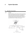
4.1.1
System Operation
Description of Laser System
Controller
The job of the controller is to provide a stable, low-noise power source for the
diode laser, set the temperature in the laser head, control wavelength scanning,
and provide readouts of all relevant laser parameters. Conceptually, the
circuitry inside the controller is built in two layers: analog and digital. The
analog layer incorporates low-noise design for temperature, current, and
wavelength fine tuning. The digital layer includes all the readouts and circuits
to set operating points and scan parameters. This layer acts as an interface
between the user (or the user’s computer) and the analog layer.
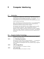
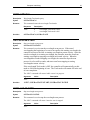
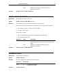
Figure 13
Controller Block Diagram
30
System Operation
The analog layer consists of four modules: current control, temperature
control, piezoelectric transducer (PZT) driver (which controls wavelength fine
tuning) and the motion control for coarse wavelength tuning.
The digital layer includes a Digital Signal Processor (DSP) and user interface
circuitry. There is a digital circuit board in the laser head that contains
information specific to each laser head such as the wavelength calibration
table and the laser head serial number.
The current driver is a low-noise, analog, DC-current supply which provides
up to hundreds of mA of current to the laser diode. The AC ripple in the
output is sub μA RMS. If desired, the current supply can be modulated at up
to 1 MHz through a BNC connector on the rear panel of the controller. For
proper operation, use only with a cable shorter than three meters.
The temperature driver controls the laser temperature by supplying current to
thermoelectric (Peltier) elements in the laser head. Precise temperature control
is achieved through the use of a two-stage system. One thermoelectric element
maintains the overall temperature of the laser cavity while another is
specifically dedicated to the diode temperature within the cavity. A DSP is
used to perform PID feedback control for each element. In this way, the laser
temperature and the surrounding environment are stabilized to within plus or
minus 10 millikelvin.
The PZT driver supplies 0–120 Volts DC to a piezoelectric fine-tuning
element in the laser head. By using the PZT system you can tune the
wavelength smoothly with sub-angstrom precision.
The Motion Control module actuates the DC motor, which provides coarse
wavelength control and scanning. For smooth tuning, a DSP is used to
generate desired motion trajectory and to perform PID feedback control of the
DC motor.
The DSP based digital board controls all of the other modules, runs the digital
displays, and provides USB interfacing capability. It also communicates with
the circuit board in the laser head to determine what kind of laser head it is
and to upload the wavelength calibration table.
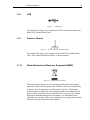
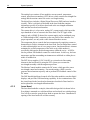
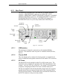
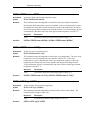
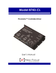
4.1.2
Laser Head
The laser head embodies a simple, ultra-stable design which is shown below.
Everything is mounted on a solid metal base and enclosed in a sealed package.
You will never need to open the laser head to operate the laser. Unauthorized
opening of the laser head will void the warranty.
System Operation
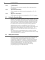
Figure 14
31
Laser Head Mechanical Schematic forTLB-6700 series laser
In this design, a diode laser is used as the gain medium. One end of the diode
laser has a high reflectivity coating which acts as an end mirror of the
external-cavity. The other end of the diode has an antireflection coating.
The diode laser is bonded to a temperature sensor and a thermoelectric cooling
block which maintains a highly stable diode temperature.
The laser beam radiating from the diode is collimated by a lens before striking
a high-quality diffraction grating. The diffraction grating is precisely aligned
at New Focus and its position is fixed with respect to the diode. From the
diffraction grating, a fraction of the beam is directed to the tuning mirror. The
position of this mirror determines the operating wavelength of the laser.
The tuning mirror is mounted on a stiff arm. An angle sensor near the pivot
point of the arm provides data for wavelength readout. The other end of the
arm is moved by a DC motor driven screw and a piezoelectric transducer
(PZT). The DC motor makes coarse wavelength changes while the PZT is
used for micron scale movements, which correspond to sub-angstrom
wavelength tuning precision.
The laser cavity is carefully adjusted to give the best tuning performance
when tuned from short to long wavelength. Therefore, when scanning the
laser, it is best to approach the desired wavelength from shorter wavelengths.
A small fraction of the output beam is directed to a power monitor. The
reading from this monitor is displayed on the front panel of the controller.
An SMA connector is available on the outside of the head enclosure for highspeed current modulation. The use of this feature is described in Section 4.11
Rear Panel.
Finally, the laser head records how many hours the diode laser has operated.
A new laser head will typically show 100-150 hours due to factory burn-in.
32
System Operation
WARNING
Before operating the Model 6700 Tunable Diode Laser, please
read and understand all of Section 1.
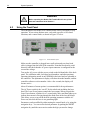
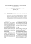
4.2
Using the Front Panel
The front panel of the Model 6700 Tunable Diode Laser is designed for easy
operation. It has various distinct areas, each with a specific set of related
functions, and a control knob, as shown in Figure 15 below.
Figure 15
Front Panel Layout
Make sure the controller is plugged into a wall socket and your laser head
cable is plugged into the back of the controller. Point the laser head in a safe
direction, and check that the AC power input connector is configured for the
correct line voltage.
Turn on the AC power with the power switch on the left-hand side of the back
panel. The calibration table, laser-head serial numbers, and other pertinent
operating information stored in an EEPROM in the laser head are uploaded to
the controller. The alphanumeric display will show the model number, and the
controller software revision number. After a few seconds, the display will
become active.
About 30 minutes of warm-up time is recommended for best performance.
The AC Power switch is the “on-off” for the whole unit including the laser
head. The Laser Power button controls the laser output. When you push the
Laser Power button, it flashes for a 3-second safety delay and then lights up to
indicate that current is flowing through the diode laser in the laser head unit.
This allows you to set up all the desired operating parameters with the AC
Power on, but while the laser is not generating light.
Parameters can be modified by either turning the control knob, or by using the
navigation keys. You can set the desired parameter by pushing the RIGHT
navigation key until the cursor arrives under the digit you need to change.
System Operation
33
Push the up/down key to change the digit value. After setting all the digits to
the desired values push the Setup/Enter button to accept the desired parameter.
4.3
Setting Current / Power
The New Focus Velocity Tunable Diode Laser is designed to run on a single
longitudinal mode. The system is typically set so that the drive current is
below the threshold of multimode operation. Under these conditions, the
current display is continuously on. However, it is possible to increase the
drive current in order to increase the output power. The trade-off is that there
is increased risk of multimode operation. The current settings for multimode
operation may be wavelength dependent. Please refer to the included
Acceptance Test Data Sheet for actual settings.
To set the desired Current/Power level press Mode button to select desired
laser diode mode of operation—constant current or constant power. Use the
UP/DOWN navigation keys to select Current/Power field in the main Menu
display. Turn the knob control to set the desired Current/Power setpoint.
4.4
Setting Wavelength
The desired wavelength can be adjusted by first navigating to the “Lambda”
field in the main Menu using the UP/DOWN navigation keys, and changing
the value by turning the knob control. The maximum and minimum
wavelengths that can be set depend upon the head rating.
If the wavelength Track Mode is ON, changing the wavelength setpoint will
automatically cause the DC motor to move the end mirror until the new
wavelength is reached.
4.5
Fine Wavelength Control
The Piezo Voltage is used for fine (sub-angstrom) wavelength tuning. A
piezoelectric transducer (PZT) is used to make adjustments in the tuning
mirror angle that are too small to be made by the DC motor. The readout is in
percent of the maximum PZT voltage from 0 to 100%.
The Piezo Voltage control can change the wavelength over a several angstrom
range, which is easily seen on a wavemeter of sufficient accuracy. (If,
however, the laser is in Track mode, the DC servo motor will counteract the
piezo and the wavelength will change relatively little.)
To change the Piezo voltage setting, first navigate to the “Piezo” field in the
main Menu using the UP/DOWN navigation keys, and changing the value by
turning the knob control.
34
System Operation
4.6
Wavelength Track Mode
The wavelength track mode can be turned ON or OFF by navigating to the
“Lambda Track” field in the main Menu using the UP/DOWN navigation
keys, and changing the value by turning the knob control.
When the track mode is turned ON, the laser wavelength is actively controlled
using the tuning motor that rotates the end mirror. When the tracking is
turned OFF, the laser runs open loop without active wavelength control.
Because of the nature of the wavelength control scheme however, note
that the wavelength of the laser is significantly more stable in Ready
mode, usually by 1 or 2 orders of magnitude, than it is in Track mode.
4.7
Setting Wavelength Scan Parameters
The laser cavity is carefully adjusted to give the best tuning performance
when tuned from short to long wavelength. Therefore, when scanning the
laser, it is best to approach the desired wavelength from the short wavelength
side. All wavelength scan related parameters are accessible from Scan
Parameters menu. To view this menu, first press the menu Setup/Enter key
and select “Set Scan Params” field using the UP/DOWN navigation keys.
With this field selected, press the Setup/Enter key again (or the RIGHT
navigation key) to enter the Scan Parameters menu.
4.7.1
Setting the Start and Stop Wavelengths
The start-of-scan wavelength can be changed by selecting the “Start λ” field
and turning the control knob, or using the navigation keys. Setting the end-ofscan wavelength is just as easy as setting the starting wavelength. This time
select “Stop λ” in the menu and then use the control knob to set the
wavelength. The laser will scan in whichever direction you set it. The stop
wavelength can be larger or smaller than the start wavelength, but it is
recommended to scan from short to long wavelengths.
4.7.2
Setting the Scan Velocity
To set the forward scan velocity, select the “Fwd Vel” field using the
UP/DOWN navigation keys and turn the control knob. The reverse (Stop λ to
Start λ) scan velocity can be set by selecting the “Rev Vel” field and turning
the control knob, or with the navigation keys. It is possible to adjust the
forward and reverse scan velocities in 0.01 nm/s increments.
4.7.3
Performing a Scan
To start a scan, push the Scan button. If the laser is at the start wavelength, it
will begin scanning at the forward scan velocity. Otherwise, it will go to the
Start wavelength at the reverse scan speed and begin the scan process. When
the laser arrives at the Stop wavelength it will stop briefly and return to Start
wavelength at reverse scan velocity.
System Operation
35
There is a Trigger input on the rear-panel of the controller. Applying a
voltage which rises above 3 V and returns to zero (falling edge) to this input is
equivalent to depressing and releasing the Scan button.
4.7.4
Stopping a Scan
If you push the Scan button in the middle of a scan or a reset, it will stop,
leaving you in Ready mode.
4.8
Laser Power Display
There is a 4-digit 7-segment display on the controller’s front panel that is
dedicated for displaying the actual laser current or power. This displayed
value depends upon the mode of operation. Actual laser current is displayed,
and “mA” LED is turned ON when the controller is in Constant Current mode.
The display can also show the laser power. The “mW” LED is turned ON
when the controller is in Constant Power mode. The ERROR LED located
below this display will be turned ON (solid RED) if the laser output has been
turned OFF by the controller due to any safety violation. If the laser output
current reaches the programmed limit, the LIMIT LED will be turned ON
(blinking YELLOW) to indicate that any further Set Current increase will be
limited.
4.9
Wavelength Display
The actual laser wavelength is shown in the 6-digit 7-segment display on the
controller’s front panel.
4.10
Menu Section
In addition to displaying status parameters on the two 7-segment LED
displays of the instrument, the Menu section of front panel enables users to
view/change many more parameters.
4.10.1
Control Knob
The control knob on the right side of the front panel is used to set the value of
all parameters. Users can select the parameter whose value needs to be
modified using the Setup/Enter and Cursor Arrow keys, and then modify the
values with the knob.
The knob has an acceleration algorithm that causes the rate of change of value
to increase as the knob is turned faster. Turning slowly allows for fine
adjustment at the smallest displayed decimal place.
4.10.2
Setup / Enter
The Setup/Enter key is used to (a) invoke the Setup screen, (b) accept
parameter change, or (c) enter a lower menu level, depending on the screen
displayed.
36
System Operation
4.10.3
Esc
The Esc key is used to (a) cancel a parameter change or (b) back up one menu
level.
4.10.4
Cursor Arrow Keys
Moves cursor UP or DOWN or between editable data fields. The DOWN
arrow decrements values in numerical entry fields, or selects a previous choice
in a multi-choice entry field. The UP arrow increments values in numerical
entry fields, or selects a next choice in multi-choice entry fields. The RIGHT
and LEFT arrow keys are used to move the cursor position in numerical entry
fields.
4.10.5
Display Elements
The Model 6700 uses a character display to depict information about the
current state of the system. The display screens shown by the instrument can
be classified as follows: title screen, laser head information screen, main
Setup screen, parameter setup screen and error message screen.
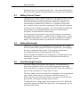
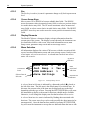
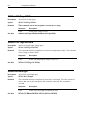
4.10.6
Menu Selection
All information displayed in various 6700 screens, with the exception of title
screen, laser head information screen and error message screen, can be in one
of two states: selected or unselected. A selected item can be in one of two
states: idle or active.
Up arrow
indicator
Lock Dial =
No
Aud. Beep = Yes
USB Address= 1
Save Settings
Unselected
items
Selected item in
idle state
Figure 16
Data
associated
with item
Down arrow
indicator
A Sample Setup Screen
A selected item in idle state is indicated by a diamond symbol () placed to
the left of the item. The idle state is the default state for a selected item. In
this state, the present value of the item may be displayed next to the label
depending upon the type of item. Pressing the SETUP/ENTER key will cause
the instrument to display a sub-menu for that item, should one be available.
Otherwise, it will change the display state for that item from idle to active.
A selected item in active state is indicated by flashing data associated with
that item. The cursor arrow keys can be used to modify the data (numerical or
non-numerical). Once the data has been modified, pressing SETUP/ENTER
key will cause the instrument to accept the new data and return the item to idle
System Operation
37
state. Pressing the Esc key will cause the display to ignore any changes made,
and return to the previous menu.
An unselected item simply displays the item name. Depending upon the item,
it may also display data associated with that item.
The Setup screens also have up () and down () indicators to show that
more items can be accessed by pressing UP and DOWN arrow keys
respectively.
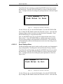
4.10.7
Title Screen
The Title screen is displayed for a few seconds every time the instrument is
powered ON. This screen is used to display the present firmware version of
the instrument. A sample Title screen is shown in Figure 17.
Firmware
version number
New Focus.
TLB6700-LN - Tunable
Laser.Controller
Ver. 1.0.0.0
Figure 17
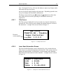
4.10.8
A Sample Title Screen
Laser Head Information Screen
The Laser Head Information screen is displayed for a few seconds after the
Title screen every time the instrument is powered ON. This screen is used to
display the model number, serial number, revision number and calibration
date of the laser head connected to the controller. A sample screen is shown
in Figure 18.
Model
S/N
Rev
Date
Figure 18
=
=
=
=
TLB-6321
P1001
2.04
11-26-2010
A Sample Laser Head Information Screen
38
System Operation
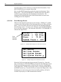
4.10.9
Main Setup Screen
The Main Setup screen is displayed after the controller has been powered ON
for a few seconds. This is the topmost level display during normal operation,
and it is used to change the laser current/power, wavelength, and piezo voltage
setpoints, besides turning the wavelength track mode ON/OFF.
A sample Main Setup screen is shown in Figure 19.
Current = 150.00mA
Lambda = 780.00nm
Piezo
=
75.00 %
Lambda Track = Off
Figure 19
4.10.10
A Sample LDD and TEC Params Measurement Screen
Parameter Setup Screens
The setup screens are used to view and modify scan and system settings.
These screens can be accessed from the Main Setup screen by pressing the
Setup/Enter key.
System Operation
39
Setup/Enter
Set Scan Params
Start λ
Stop λ
Fwd Vel
Rev Vel
Num Scans
Low Rev Pwr
Set System Params
Brightness
Lock Dial
Aud. Beep
USB Address
Wav. Input
PZT Gain
Home Lambda
Save Settings
Bin Number
Save
Recall Settings
Bin Number
Recall
Get System Status
Las Temp
Cav Temp
Las Pwr
Aux Volt
Wav Volt
PZT Volt
On Time
Tot Time
Get Laser Head Inf
Model
S/N
Rev
Date
Figure 20
Model 6700 Menu Structure
40
System Operation
4.10.10.1
Set System Params Menu
The Set System Params menu item is used to change display brightness, lock
the dial on the front panel, turn beeper ON/OFF, USB address, and to
save/recall system settings
To modify these constants, use the UP and DOWN arrow keys to select this
menu item. Press the SETUP/ENTER key to enter a sub-menu for this item.
A sample sub-menu for setting the system parameters is shown in the figure
below.
Brightness = 100%
Lock Dial =
No
Aud. Beep = Yes
USB Address= 1
Figure 21
A Sample System Parameters Sub-menu
Use the UP and DOWN arrow keys to select the parameter that needs to be
modified. Once the desired item has been selected, press the SETUP/ENTER
key to change the item’s state from idle to active. Once the item is in active
state, use the cursor keys to specify a desired value. Once the desired value
has been selected, press SETUP/ENTER key to accept the new value. The
new parameters will take effect immediately, and the menu item will be
returned to idle state. Press Esc key to cancel any changes or to return to Set
System Params main menu.
4.10.10.2
Save Settings Menu
The Save Settings menu item is used to store the instrument’s setup
configurations for future use. For example, a specific test setup may be saved
for later use, and then another setup may be used presently. When the user
desires to perform the specific test, its setup is simply recalled.
Non-volatile flash memory is used for saving the instrument’s parameters.
When a save operation is performed, all of the parameters which are currently
in effect on the instrument are stored. The user selects a “bin” number for
saving the parameters, up to the maximum available in the instrument. Then,
when that “bin” number is recalled, the instrument is reconfigured to the
previously stored values. A special “bin 0” is reserved for the reset state.
Recalling bin 0 will reset the unit to factory defaults.
System Operation
41
To perform the save operation, use the UP and DOWN arrow keys to select
this menu item. Press the SETUP/ENTER key to enter a sub-menu for this
item. A sample sub-menu for setting the system parameters is shown in figure
below.
Bin Number = 1
Push Enter to Save
Figure 22
A Sample Save Parameters Sub-menu
Use the UP arrow key to select the Bin Number. Press the SETUP/ENTER
key to change the Bin Number menu state from idle to active. Once the item
is in active state, use the cursor keys to select the desire bin number. Press
SETUP/ENTER key to accept the desired bin.
Now, use the DOWN arrow key to select the menu item that states “Press
Enter to Save”. Press SETUP/ENTER key with this menu item selected to
save the system settings to the bin number selected earlier. The instrument
will automatically return to the Measurement screen once the saving process
has completed.
4.10.10.3
Recall Settings Menu
The Recall Settings menu item is used to recall previously saved instrument’s
setup configurations. Recalling bin 0 will reset the unit to factory defaults.
To perform the recall operation, use the UP and DOWN arrow keys to select
this menu item. Press the SETUP/ENTER key to enter a sub-menu for this
item. A sample sub-menu for recalling the system parameters is shown in
figure below.
Bin Number = 1
Push Enter to Rcl.
Figure 23
A Sample Save Parameters Sub-menu
Use the UP arrow key to select the Bin Number. Press the SETUP/ENTER
key to change the Bin Number menu state from idle to active. Once the item
42
System Operation
is in active state, use the cursor keys to select the desire bin number. Press
SETUP/ENTER key to accept the desired bin.
Now, use the DOWN arrow key to select the menu item that states “Press
Enter to Rcl”. Press SETUP/ENTER key with this menu item selected to
recall the system settings from the bin number selected earlier. The
instrument will automatically return to the Measurement screen once the
recalling process has completed.
4.10.10.4
Error Message Screen
Whenever the instrument generates an error message, a flashing “E” symbol
is shown on the left-top corner of the Measurement screen as shown in figure
below. Users can retrieve this error message from the instrument from the
Error Message screen. To retrieve error messages, press the SETUP/ENTER
key to view the setup menu. The first menu item will be “GET ERRORS” as
shown in the figure below.
Error
Message
Indicator
Current = 150.00mA
Lambda = 780.00nm
Piezo
=
75.00 %
Lambda Track = Off
Figure 24
A Sample Main Setup Screen when Errors Present
GET
Set
Set
Get
Figure 25
ERRORS
Scan Params
System Params
System Status
A Sample Setup Screen when Errors Present
Select the Get Errors menu item by pressing the UP arrow key. Once this
item is selected press SETUP/ENTER key to enter the Error Messages screen.
All the error messages generated are listed on this screen in a chronological
order (oldest first). All the error messages can be viewed by pressing the UP
and DOWN arrow keys. Press the Esc key to return to the Setup screen. Note
that this process removes the errors from error buffer, and they will not be
available for querying via USB communication interface.
System Operation
4.11
43
Rear Panel
The Model 6700 rear panel has a USB connector, a LASER CONTROL
connector, a TRIGGER INPUT connector, an AUXILIARY INPUT
connector, a FREQUENCY MODULATION INPUT connector, a CURRENT
MODULATION INPUT connector, a WAVELENGTH INPUT connector, a
WAVELENGTH OUTPUT connector, an INTERLOCK connector, a
POWER SWITCH, the AC power entry module and a GROUND post.
Frequency
Modulation
Interlock
Current
Modulation
Trigger
Input
Wavelength
Input
Wavelength
Output
Chassis
Ground
Auxiliary
Input
Figure 26
4.11.1
Rear Panel
USB Interface
The instrument is designed to communicate with standard USB Host
interfaces. The connector on the rear panel is a standard USB-B (Full-Size,
Device).
4.11.2
Chassis GND
This 4 mm banana jack is connected to chassis ground. It is intended to be
used as an additional earth ground connection for the Model 6700’s enclosure.
4.11.3
AC Power
The Model 6700 can be operated on either 50 or 60 Hz mains power. The
instrument can be configured for operation at the following nominal AC line
voltages -- 100, 120, 220, 230, or 240 VAC. See section 3.6 for information
on properly configuring the Model 6700 for the available mains power.
The line cord supplied with each unit should be plugged only into a properly
grounded outlet to prevent electrical shock in the event of an internal short
circuit to the metal cabinet. The detachable line cord should be connected to
the IEC320 connector on the power entry module.
44
System Operation
4.11.4
Fuses
The correct fuses must be installed into the fuse holder that is part of the AC
power entry module. Please check the fuse label on the rear panel, before
installing new fuses (see Figure 26).
WARNING
To avoid electric shock, the appropriate fuses for the AC input
power voltage must be installed in the instrument. Only
qualified service personnel should replace fuses. Failure to
observe these precautions can result in fire, severe injury or
death.
4.11.5
Frequency Modulation Input
The Frequency Modulation input is for external analog control of the
wavelength through the voltage applied to the PZT on the tuning arm. It is
useful for making fine-frequency adjustments and for FM spectroscopy.
Sweeping the Frequency Modulation input from -3 V to +3 V corresponds to
changing the laser frequency by an amount on the order of -30 GHz to +30
GHz for certain models. The actual modulation you will observe depends on
the wavelength range of the laser head (see the Acceptance Test Data Sheet of
your particular laser) and on the rate and amplitude of the incoming signal (for
example, full 30-GHz modulation is only available at rates up to 200 Hz). The
Frequency Modulation input will accept triangle waveforms from DC to 2
kHz with an amplitude of +/-0.3 V, and DC to 700 Hz with an amplitude of
+/-3V. The instrument will protect itself from going over these signal values,
to prevent overheating of the piezo actuator or internal circuitry. The
protection gradually decreases the input amplitude if the user inadvertently
goes over the specified amplitude values. In the rare occasions when the unit
overheats, especially when the vents are obstructed or the temperature in the
room is above specifications, the unit will temporarily reduce the input signal
amplitude to 1/10 of the maximum value. The instrument automatically
resumes normal operation when the user responds appropriately to cool the
system or reduce the input signal or frequency.
Decreasing voltage at the Frequency Modulation input corresponds to a
decrease in piezo voltage and an increase in laser frequency (or a decrease in
laser wavelength). This decrease in piezo voltage is effectively subtracted
from the front-panel knob setting, and the front-panel display reads the result.
System Operation
4.11.6
45
Current Modulation Input
The Current Modulation input allows you to modulate the diode current at
rates up to 1 MHz. This input accepts -10 to +10 V into a DC-coupled 5 k Ω
resistive load and provides 0.2 mA/V modulation. This input is summed with
the front-panel setting. Note that the front panel current readout does not
reflect the modulation input.
4.11.6.1
High-Speed Current Modulation
For high-speed current modulation up to 100 MHz, an SMA connector on the
laser head is provided. This input is AC coupled; the low- and high-frequency
roll off points are below 10 kHz and about 100 MHz, depending on the model.
The current modulation provided by this input is approximately 20 mA/V. To
prevent damage to the diode laser, the voltage swing on this input must be less
than 1 Vp-p.
CAUTION
This is a direct RF connection to the laser diode. Improper use
could destroy the diode. Do not exceed 1 V peak-to-peak input.
Avoid static discharge.
Since this is a direct connection to the diode laser, there is no current limiter
that prevents too much current from passing through the diode. Thus, there is
a danger of destroying the diode if the maximum current is exceeded. Be sure
that the current modulation applied to the laser diode will not result in driving
the diode above its maximum current. (See included Acceptance Test Data
Sheet.)
The high-speed input has a protective shorting cap which should remain in
place during normal operation. When removing the shorting cap to connect a
high-frequency driver, be sure to wear a ground strap to prevent static
discharge. Please contact New Focus if you have any questions on how to use
the high-speed modulation input. Make sure to turn off power to the diode
before connecting any device to the high-speed input.
4.11.7
Wavelength Output
The Wavelength Output BNC connector provides a signal from 0 to 10 V that
corresponds linearly to the laser output wavelength. This connection has 2 k Ω
output impedance. Zero volts are output at the minimum operating wavelength
for the laser head connected to the controller. The voltage increases with
wavelength according to the equation:
V = 10 * (actual – min) / (max – min)
where max and min are the maximum and minimum wavelength ratings
(nm) of the laser head, actual is the actual wavelength (nm) and V is the
Wavelength Output voltage (V).
46
System Operation
4.11.8
Wavelength Input
The Wavelength Input connector is for coarse analog control of the
wavelength. For example, you could use it for your own analog wavelength
scanning control. The DC voltage that you apply to the Wavelength Input is
digitized and a wavelength setpoint for wavelength control is determined.
_setpoint = 0.1 * (max – min) * V + min
where max and min are the maximum and minimum wavelength ratings
(nm) of the laser head, and V is the Wavelength Input voltage (V).
If this feature is used for scanning, please adjust the wavelength input
modulation frequency such that the rate of change of _setpoint does not
exceed head’s maximum scan speed.
If your analog control signal is not too noisy you should be able to control the
wavelength in Angstrom or even sub-Angstrom increments. Note however,
that if you do not have a quiet analog control voltage, this mode of operation
has less wavelength stability than Track mode.
If you want to use the Wavelength Input connector, you must first place the
laser in Wavelength Input mode via local menu interface (Set System Params
menu – Wav. Input setting) or remote command (SYSTem:WINPut). The
laser will immediately begin changing to the wavelength which corresponds to
the voltage at the input. The Wavelength Input connector accepts a DC signal
between 0 and 10 V that corresponds linearly to the laser output wavelength in
the same way as the Wavelength Output jack does. The input impedance of
this control is 27 k Ω. Note that an unconnected wavelength input corresponds
to zero volts and the minimum wavelength. If the maximum voltage is
exceeded, the diode laser will tune to its maximum wavelength and stop.
To exit Wavelength Input mode, go to the Set System Params menu and set
“Wav. Input” parameter to “OFF”. Also, if you exit Track mode and then reenter, the laser will still be in Wavelength Input mode.
4.11.9
Auxiliary Input
The Auxiliary Input is a 16-bit analog-to-digital converter input to the digital
signal processor (DSP). Analog signals that you connect here can be read out
by your computer when you use remote control. This is a general-purpose
input that allows you to collect data from a photodetector during a wavelength
scan or, for example, to create your own Constant-Power mode with an
external detector. The Auxiliary Input will accept signals from 0 to +5 volts
and presents a 40 kΩ load.
System Operation
4.12
47
Constant Power Mode
Constant Power mode provides an easy way to remove the power modulation
due to the étalon effect caused by the residual facet reflectivity when scanning
the wavelength, or to stabilize the laser power to minimize long -term power
drift. A digital feedback loop is implemented in the firmware to keep the laser
power at a set level by controlling the laser current. Because of the relatively
long loop time (~ 10 ms), we recommend using this mode with a scan speed
under 1% of the maximum speed.
To enable and disable Constant Power mode, select accordingly via front
panel menu options. After leaving this mode, the power setting is stored in
memory.
48
System Operation
This page is intentionally left blank
5
5.1
Computer Interfacing
Introduction
The Model 6700 Tunable Laser Controller has a USB interface to receive
commands from, and send responses to, a host PC. The commands supported
by the controller can be divided into the following two categories:
commands that cause it to take a desired action, and commands (queries) that
cause it to return a stored value.
Query commands must end with a question mark (?). It is recommended that
when a query command is sent, the response to that command from the
instrument be read before issuing any other command.
Set commands, on the other hand, are used to configure/setup the controller
for a desired mode of operation. These commands take at least one
parameter. If the controller executed the command successfully, it responds
with an “OK” string. Otherwise, it returns an error message. The subsequent
sections in this chapter detail the communication protocols supported by the
instrument.
5.2
Computer Interface Terminology
Listed below are the key abbreviations and concepts used in the command
reference section of this manual.
5.2.1
<…> Delimiting Punctuation
For the purposes of this manual, any string enclosed by <…> is considered to
be a command, a string or numerical argument. The punctuation <…> is
used to symbolize the typographic limits of the command, string or argument
in question.
5.2.2
<CR> Carriage Return
The ASCII encoded byte 13 in decimal. (0D hex)
5.2.3
<LF> Line Feed
The ASCII encoded byte 10 in decimal. (0A hex)
50
Computer Interfacing
5.2.4
(;) Semicolons
Semicolons are used to separate commands within a single transmission
(concatenation).
5.2.5
Command Termination
All the commands sent to the driver must be terminated by a <CR><LF>
sequence.
5.2.6
Response Termination
All the responses from the driver are terminated by a <CR><LF> sequence.
5.3
Controller Operation Mode
The Tunable Laser Controller supports two modes of operation: LOCAL and
REMOTE. The controller will be in LOCAL mode, by default, following a
power reset. In this mode, all the main setpoints, scan parameters and other
system parameters can be adjusted by turning the control knob on the front
panel of the controller. Output can be turned ON and OFF by pressing the
Laser Power button. Please refer the “System Operation” chapter for a
detailed description on how to accomplish these tasks. When it is in
REMOTE mode, knob control is disabled; setpoints and other settings can be
adjusted only by issuing appropriate commands from a host PC. The
REMOTE or LOCAL status indicator character can be found in the LCD
display.
The controller can be put into REMOTE mode by issuing the command
“SYSTem:MCONtrol REM”. It can be put back in LOCAL mode by issuing
“SYSTem:MCONtrol:LOC” command.
5.4
USB Communication
The instrument is designed to communicate with a host PC via a standard
USB interface. Before connecting the instrument to the USB interface the
user should install the application included in the software CD that
accompanies the Tunable Laser Controller. The application automatically
installs the right USB drivers. Communication can be done through this
interface by using the application or by developing software in the user’s
preferred programming language. The software CD contains
communication drivers and example programs in the following
programming languages: LabVIEW and C#.NET
Computer Interfacing
5.5
5.5.1
51
Commands Summary
Conventions
There are two types of device commands: commands that cause the
instrument to take a desired action, and queries that return a stored value or
state of the instrument. Queries must end with a question mark (?), while
commands may require parameter(s) to follow:
SOURce:WAVElength:START 780.00
For example, the value “780.00” in the command
SOURce:WAVElength:START 780.00 sets the start scan wavelength to
780.00 nm. The command/query MUST contain all of the letters shown in
upper-case; lower-case letters in the commands are optional, and may be used
for clarity.
The commands may be sent to the instrument in either upper or lower case or
in any combination. For example, the following commands are equal:
SOURce:WAVElength:START 780.00
SOUR:WAVE:START 780.00
source:wave:start 780.00
Source:Wavelength:Start 780.00
COMMAND TERMINATION:
All commands sent to the controller must be terminated by <Carriage
Return><Line Feed>.characters. All responses sent out by the controller are
terminated by the same characters.
5.5.2
Types of Commands
There are six general types of commands: Standard Commands, Output
Commands, Sense Commands, Source Controls, Source Queries, and System
Commands.
Standard Commands allow you to get information about the laser head and to
query whether an operation has been completed. Output Commands tell the
laser to start some action such as starting or stopping a scan or reset. System
Commands set the operating mode of the controller.
Source Controls set laser operating parameters. Each Source Control has an
accompanying Query. Source Queries return the value of various controller
set points.
52
Computer Interfacing
Sense Commands return the value of various laser operating conditions.
Note that there is an important difference between Sense Commands and
Source Queries. Sense Commands read actual voltages, currents,
temperatures, or wavelengths; the value returned is the same as that seen on
the controller front panel at the time the command is executed. In contrast,
Source Queries read set points (values that are theoretical goals). These
values may not necessarily match the values displayed on the front panel.
For instance, the queried diode current and piezo voltages can differ from the
actual values by up to 3% due to component variations such as resistor
tolerances. However, in the case of wavelength queries, the wavelength set
by a Source Command will match the wavelength returned by a Source
Query because each laser is factory calibrated and has its specific
wavelength-calibration table loaded into the laser head.
The next section has an index of all the possible computer control commands.
Then, the pages that follow the index of commands give detailed information
about each command, including a description of the command and examples
of how the command is used.
Computer Interfacing
5.5.3
53
Index of Commands
Standard Commands
Syntax
Description
*IDN?
*RCL
*RST
*SAV
*STB?
*OPC?
BEEP
BEEP?
BRIGHT
BRIGHT?
ERRSTR?
LOCKOUT
LOCKOUT?
ONDELAY
ONDELAY?
Identification string query
Recall controller settings
Reset the controller
Save controller settings
Query status byte
Query operation complete status
Set controller beeper status
Query controller beeper status
Set Menu display brightness level
Query Menu display brightness
Query error string
Set controller front panel state
Query controller front panel state
Set laser output ON delay
Query laser output ON delay
Output Commands
Syntax
Description
OUTPut:STATe
OUTPut:STATe?
OUTPut:TRACk
OUTPut:TRACk?
OUTPut:SCAN:START
OUTPut:SCAN:STOP
OUTPut:SCAN:RESET
Set laser output enable state
Query laser output enable state
Set wavelength track mode
Query wavelength track mode
Start wavelength scan process
Stop wavelength scan process
Reset wavelength scan process
Sense Commands
Syntax
Description
SENSe:CURRent:DIODe
SENSe:POWer:DIODe
SENSe:TEMPerature:DIODe
SENSe:TEMPerature:CAVity
SENSe:VOLTage:AUXiliary
SENSe:VOLTage:PIEZo
SENSe:VOLTage:WAVEIN
Sense diode current
Sense diode power
Sense diode temperature
Sense cavity temperature
Sense voltage from auxiliary input
Sense piezo actuator actual voltage
Sense voltage from wavelength
input
Sense output wavelength
SENSe:WAVElength
Source Control Commands
Syntax
Description
SOURce:CPOWer
SOURce:CURRent:DIODe
SOURce:POWer:DIODe
SOURce:VOLTage:PIEZo
SOURce:VOLTage:PZGAIN
Set constant power mode
Set diode current setpoint
Set diode power setpoint
Set piezoelectric voltage setpoint
Set piezoelectric voltage gain
54
Computer Interfacing
SOURce:WAVElength
SOURce:WAVE:DESSCANS
SOURce:WAVE:SCANCFG
SOURce:WAVE:START
SOURce:WAVE:STOP
SOURce:WAVE:SLEW:FORWard
SOURce:WAVE:SLEW:RETurn
Set diode wavelength setpoint
Set desired number of scans
Set scan configuration
Set starting wavelength for scan
Set stopping wavelength for scan
Set wavelength scan forward
velocity
Set wavelength scan return velocity
Source Query Commands
Syntax
Description
SOURce:CPOWer?
SOURce:CURRent:DIODe?
SOURce:POWer:DIODe?
SOURce:TEMPerature:DIODe?
SOURce:TEMPerature:CAVity?
SOURce:VOLTage:PIEZo?
SOURce:WAVElength?
SOURce:WAVE:ACTSCANS?
SOURce:WAVE:DESSCANS?
SOURce:WAVE:SCANCFG?
SOURce:WAVE:START?
SOURce:WAVE:STOP?
SOURce:WAVE:MAXVEL?
SOURce:WAVE:SLEW:FORWard?
Query constant power mode
Query diode current setpoint
Query diode power setpoint
Query diode temperature setpoint
Query cavity temperature setpoint
Query piezoelectric voltage setpoint
Query diode wavelength setpoint
Query actual number of scans
Query desired number of scans
Query scan configuration
Query starting wavelength for scan
Query stopping wavelength for scan
Query wavelength scan max.velocity
Query wavelength scan forward
velocity
Query wavelength scan return
velocity
SOURce:WAVE:SLEW:RETurn?
System Commands
Syntax
Description
SYSTem:ENTIME?
SYSTem:MCONtrol
SYSTem:MCONtrol?
SYSTem:WINPut
SYSTem:WINPut?
SYSTem:LASer:MODEL?
SYSTem:LASer:SN?
SYSTem:LASer:REV?
SYSTem:LASer:CALDATE?
Query laser usage time
Set controller operation mode
Query controller operation mode
Set wavelength input mode
Query wavelength input mode
Query laser model number
Query laser serial number
Query laser revision number
Query laser calibration date
Computer Interfacing
5.6
55
Commands and Queries
*IDN?
Description
Identification string query.
Syntax
*IDN?
Remarks
This query will cause the instrument to return an identification string.
Model
Name
Firmware
Version #
Firmware
Date
Controller
Serial #
NEW_FOCUS XXXX vYYY mm/dd/yy, SNZZZZ
*RCL
Description
Recall command.
Syntax
*RCL Bin
Argument
Value
Description
Bin
0
1 to 5
Restores factory default settings
Restores settings saved in specified bin
Remarks
This command restores the instrument to the setup states saved in instrument’s nonvolatile flash memory. The parameters that can be restored are:
1. USB address
2. Beeper enable state
3. LCD display brightness
4. Dial (rotary knob) lockout state
5. Laser mode
6. Diode current setpoint
7. Diode power setpoint
8. Diode temperature setpoint
9. Cavity temperature setpoint
10. Wavelength input enable state
11. Wavelength setpoint
12. Piezo voltage setpoint
13. Starting wavelength for scan process
14. Stopping wavelength for scan process
15. Forward scan velocity
16. Return scan velocity
See Also
*RST, *SAV
56
Computer Interfacing
*RST
Description
Reset command.
Syntax
*RST
Remarks
This command performs a soft reset of the instrument.
See Also
*RCL
*SAV
Description
Save command.
Syntax
*SAV Bin
Argument
Value
Description
Bin
2 to 5
Saves current settings to specified bin
Remarks
This command stores the current state of the instrument in non-volatile flash memory.
This state is then recalled using the *RCL command. See description of *RCL command
for a list of values saved/recalled by the instrument.
See Also
*RCL
*OPC?
Description
Operation Complete Query.
Syntax
*OPC?
Remarks
The laser has three long-term operations: wavelength scanning, wavelength scan resetting
and setting the wavelength. Starting any of these three operations clears the OPC status
bit. When the laser reaches the target wavelength, the OPC status bit is set to 1. The bit
is also set to 1 if the movement is interrupted by stopping/resetting the scan process or by
turning OFF the wavelength Track mode. This query command returns the OPC status
bit.
See Also
Response
Description
Status = 0
Status = 1
Performing a long-term operation
Not performing a long-term operation; system is available
OUTPut:SCAN:START; OUTPut:SCAN:STOP; OUTPut:SCAN:RESET;
OUTPut:TRACk; SOURce:WAVElength
Computer Interfacing
57
*STB?
Description
Status byte Query.
Syntax
*STB?
Remarks
This command is used to query the status of the controller. A response of 128, implies
that the controller’s error buffer is not empty. This buffer can be emptied by issuing
“ERRSTR?” command and reading error messages from the controller.
See Also
Response
Description
Status = 0
Status = 128
The error buffer is empty
The error buffer is not empty
ERRSTR?
BEEP
Description
Beep command
Syntax
BEEP beep set
Remarks
This command controls the instrument’s beeper. The beeper is used to signal error or
warning conditions.
See Also
Response
Value Description
beep set
0
1
2
Beeper off
Beeper on
Test beeper (100ms beep)
BEEP?
BEEP?
Description
Beep query
Syntax
BEEP?
Remarks
This query returns the enable status of the beeper.
See Also
Response
Description
beep set
0
1
BEEP
Beeper off
Beeper on
58
Computer Interfacing
BRIGHT
Description
Display brightness command
Syntax
BRIGHT brightness
Remarks
This command controls the brightness of the controller display.
See Also
Argument
Value
Description
brightness
Integer
Brightness, in percentage, from 1% to 100%
BRIGHT?
BRIGHT?
Description
Display brightness query
Syntax
BRIGHT?
Remarks
This query returns the display brightness setting.
See Also
Response
Description
brightness
Display brightness, in percentage.
BRIGHT
ERRSTR?
Description
Error string query.
Syntax
ERRSTR?
Remarks
This query returns a single error code along with the corresponding error text
string that occurred since the last error query. Refer to Appendix A for a list of
error codes and strings generated by the instrument.
See Also
Response
Description
Error code, “text”
Error code and text for error code as per chapter, 0 if no errors
ERRors?
LOCKOUT
Description
Lockout the instrument front panel.
Syntax
LOCKOUT Value
Remarks
This command can be used to lockout all the buttons and dial knob or just the dial knob
on the front panel.
Computer Interfacing
See Also
59
Argument
Value
Description
Value
0
1
2
Front panel buttons and dial knob enabled
Front panel buttons and dial knob disabled
Front panel dial knob disabled
None
LOCKOUT?
Description
Instrument front panel lockout state query.
Syntax
LOCKOUT?
Remarks
This query returns the instrument’s front panel lockout state.
See Also
Response
Description
Value
Front panel lockout state
LOCKOUT
ONDELAY
Description
Syntax
Laser turn on delay command.
ONDELAY time
Remarks
This command controls the laser turn on delay. This is the amount of time between the
moment the laser on command is received and the moment the output is actually
energized. This setting is also used when a laser is commanded to turn on by pushing the
LASER POWER button on front panel of instrument when it is in local control mode.
See Also
Argument
Value
Description
Time
Integer
Time, in milliseconds. Valid values are between 3000
and 60000
ONDELAY?, LAS:OUT, LAS:OUT?
ONDELAY?
Description
Syntax
Laser turn on delay query
ONDELAY?
Remarks
This command returns the laser turn on delay time.
See Also
Response
Description
Value
Time, in milliseconds
ONDELAY, LAS:OUT, LAS:OUT?
60
Computer Interfacing
OUTPut:STATe
Description
Syntax
Laser output enable command.
OUTPut:STATe State
Remarks
This command turns the laser ON or OFF. When turning the laser ON, the light above
the front panel’s LASER POWER switch will flash for five seconds (default) before the
power is turned ON. The flash time can be changed using the ONDELAY command.
Argument
Value
Description
State
String or Integer
0 or OFF turns the laser OFF
1 or ON turns the laser ON
See Also
ONDELAY?; OUTPut:STATe?
OUTPut:STATe?
Description
Syntax
Laser output enable state query
OUTPut:STATe?
Remarks
This command returns the laser output enable state.
See Also
Response
Description
Value
0
1
laser output OFF
laser output ON
ONDELAY; OUTPut:STATe
OUTPut:TRACk
Description
Syntax
Wavelength Track mode command.
OUTPut:TRACk Mode
Remarks
This command is used to turn the wavelength Track mode ON or OFF. When the Track
mode is turned ON, the laser wavelength is actively controlled using the tuning
motor that rotates the end mirror. When the tracking is turned OFF, the laser runs
open loop without active wavelength control. Because of the nature of the
wavelength control scheme however, note that the wavelength of the laser is
significantly more stable when the Track mode is turned OFF.
Argument
Value
Description
Mode
String or Integer
0 or OFF turns the Track mode OFF
1 or ON turns the Track mode ON
See Also
OUTPut:TRACk?; SOURce:WAVE?
Computer Interfacing
61
OUTPut:TRACk?
Description
Syntax
Wavelength Track mode query
OUTPut:TRACk?
Remarks
This command returns the wavelength Track mode.
See Also
Response
Description
Value
0
1
wavelength Track mode is OFF
wavelength Track mode is ON
OUTPut:TRACk; SOURce:WAVE
OUTPut:SCAN:START
Description
Syntax
Start wavelength scan process.
OUTPut:SCAN:START
Remarks
This command is used to start the wavelength scan process. If the actual
wavelength at the beginning of a scan is not equal to the starting wavelength, the
controller will move the laser to starting wavelength at return velocity. Once the
actual wavelength is at starting wavelength, the controller starts the scan from
starting wavelength to stopping wavelength at forward velocity. When the
wavelength has reached stopping wavelength, the controller stops the scan
process for a few milli-seconds, and starts scan from stopping to starting
wavelength at return velocity.
If the wavelength Track mode is OFF, the controller will automatically set this
mode to ON at the beginning of scan. The Track mode will remain ON at the end
of scan completion.
The *OPC? command will return 0 while a scan is in progress.
Argument
Value
Description
None
See Also
*OPC?; SOURce:WAVE:START; SOURce:WAVE:STOP
OUTPut:SCAN:STOP
Description
Syntax
Stop wavelength scan process.
OUTPut:SCAN:STOP
Remarks
This command is used to stop the wavelength scan process.
The *OPC? command will return 1 once the scan is stopped.
Argument
None
Value
Description
62
See Also
Computer Interfacing
*OPC?; SOURce:WAVE:START; SOURce:WAVE:STOP
OUTPut:SCAN:RESET
Description
Syntax
Reset wavelength scan process.
OUTPut:SCAN:RESET
Remarks
This command is used to reset the wavelength scan process. When this command is
received by the controller, it will stop the scan, wait a few milli-seconds and move
the laser to starting wavelength.
The *OPC? command will return 1 once the scan is stopped.
Argument
Value
Description
None
See Also
*OPC?; SOURce:WAVE:START; SOURce:WAVE:STOP
SENSe:CURRent:DIODe
Description
Syntax
Actual laser diode current query
SENSe:CURRent:DIODe
Remarks
This command returns the magnitude of actual laser diode current. The value returned is
same as that seen on the front panel of the controller at the time this command is
executed.
See Also
Response
Description
Value
Actual laser diode current in milliamperes (mA).
SOURce:CURRent:DIODE; SOURce:CURRent:DIODE?
SENSe:POWer:DIODe
Description
Syntax
Actual laser diode power query
SENSe:POWer:DIODe
Remarks
This command returns the magnitude of actual laser diode output power. The value
returned is same as that seen on the front panel of the controller at the time this command
is executed.
See Also
Response
Description
Value
Actual laser diode output power in milliwatts (mW).
SOURce:POWer:DIODE; SOURce:POWer:DIODE?
Computer Interfacing
63
SENSe:TEMPerature:DIODe
Description
Syntax
Actual laser diode gain element temperature query
SENSe:TEMPerature:DIODe
Remarks
This command returns the magnitude of actual laser diode gain element temperature.
Note that the diode temperature is actively controlled. If the room temperature ever gets
so high that the coolers have insufficient capacity to reduce the temperature, the control
loop can become unstable and destroy the cooling elements. To prevent damage, the laser
is automatically shut down if the laser-diode gain element temperature exceeds 35 oC.
See Also
Response
Description
Value
Actual laser diode gain element temperature in degC (oC).
SOURce:TEMPerature:DIODe; SOURce:TEMPerature:DIODe?
SENSe:TEMPerature:CAVity
Description
Syntax
Actual laser cavity temperature query
SENSe:TEMPerature:CAVity
Remarks
This command returns the magnitude of actual laser cavity temperature. The laser cavity
temperature is actively maintained by the controller at about 30oC. If the room
temperature ever gets so high that the coolers have insufficient capacity to reduce the
temperature, the control loop can become unstable and destroy the cooling elements.
To prevent damage, the laser is automatically shut down if the laser-diode gain element
temperature exceeds 35 oC.
See Also
Response
Description
Value
Actual laser diode gain element temperature in degC (oC).
SOURce:TEMPerature:CAVity; SOURce:TEMPerature:CAVity?
SENSe:VOLTage:AUXiliary
Description
Syntax
Actual auxiliary detector input voltage query
SENSe:VOLTage:AUXiliary
Remarks
This command returns the magnitude of actual auxiliary detector input voltage. The
resolution of this voltage is about 79µV.
See Also
Response
Description
Value
Actual auxiliary detector input voltage in Volts (V).
SENSe:VOLTage:WAVEIN
64
Computer Interfacing
SENSe: VOLTage:PIEZo
Description
Syntax
Actual piezo voltage query
SENSe:VOLTage:PIEZo
Remarks
This command returns the magnitude of actual piezo voltage.
See Also
Response
Description
Value
Actual piezo voltage in Volts.
SOURce:VOLTage:PZGAIN; SOURce:VOLTage:PIEZo
SENSe:VOLTage:WAVEIN
Description
Syntax
Actual wavelength input voltage query
SENSe:VOLTage:WAVEIN
Remarks
This command returns the magnitude of actual wavelength input voltage. The resolution
of this voltage is about 0.16mV.
See Also
Response
Description
Value
Actual wavelength input voltage in Volts (V).
SENSe:VOLTage:AUXiliary
SENSe:WAVElength
Description
Syntax
Actual laser wavelength query
SENSe:WAVElength
Remarks
This command returns the magnitude of actual laser wavelength. The value returned is
same as that seen on the front panel of the controller at the time this command is
executed.
See Also
Response
Description
Value
Actual laser wavelength in nanometers (nm).
SENSe:CURRent:DIODE; SENSe:POWer:DIODE
Computer Interfacing
65
SOURce:CPOWer
Description
Syntax
Constant power mode set
SOURce:CPOWer Value
Remarks
This command enables/disables Constant Power mode.
If the laser output is ON and a mode change is commanded:
The output is turned OFF.
The controller returns “OUTPUT DISABLED DUE TO MODE CHANGE”
The desired mode is set.
If the laser output is OFF and a mode change is commanded:
The desired mode is set.
The controller returns “OK”
Argument
Value
Description
Value
OFF or 0
If the string “OFF” or 0 is specified as value, the
controller is set to Constant Current mode.
If the string “ON” or 1 is specified as value, the
controller is set to Constant Power mode.
ON or 1
See Also
SOURce:CPOWer?
SOURce:CURRent:DIODe
Description
Diode laser current set.
Syntax
SOURce:CURRent:DIODe Value
Remarks
This command sets the diode laser current.
If the value specified is greater than the diode current rating:
The controller returns “VALUE OUT OF RANGE”.
No other action is taken.
If the value is in range:
The diode laser current is changed to specified value.
The controller returns “OK”.
Argument
Value
Description
Value
MAX
If the string “MAX” is specified as value, the diode
current setpoint is set to the diode’s current rating
Desired diode laser current in milliamperes (mA)
Float
See Also
SOURce:CURRent:DIODe?
66
Computer Interfacing
SOURce:POWer:DIODe
Description
Diode laser output power set.
Syntax
SOURce:POWer:DIODe Value
Remarks
This command sets the diode laser output power.
If the value specified is greater than the diode power rating:
The controller returns “VALUE OUT OF RANGE”.
No other action is taken.
If the value is in range:
The diode laser power is changed to specified value.
The controller returns “OK”.
Argument
Value
Description
Value
MAX
If the string “MAX” is specified as value, the diode
power setpoint is set to the diode’s power rating
Desired diode laser power in milliwatts (mW)
Float
See Also
SOURce:POWer:DIODe?
SOURce:VOLTage:PIEZo
Description
Piezoelectric transducer voltage set.
Syntax
SOURce:VOLTage:PIEZo Value
Remarks
This command sets the piezoelectric transducer voltage.
If the value specified is greater than 100:
The controller returns “VALUE OUT OF RANGE”.
No other action is taken.
If the value is in range:
The piezo voltage is changed to specified value.
The controller returns “OK”.
Argument
Value
Description
Value
MAX
If the string “MAX” is specified as value, the piezo
voltage setpoint is set to 100%
Desired piezo voltage in percentage (%)
Float
See Also
SOURce:VOLTage:PIEZo?
Computer Interfacing
67
SOURce:VOLTage:PZGAIN
Description
Piezoelectric transducer voltage gain set.
Syntax
SOURce:VOLTage:PZGAIN Value
Remarks
This command sets the piezoelectric transducer voltage gain.
If the value specified is greater than 1:
The controller returns “VALUE OUT OF RANGE”.
No other action is taken.
If the value is in range:
The piezo voltage gain is changed to specified value.
The controller returns “OK”.
Argument
Value
Value
HIGH or 1
LOW
See Also
Description
If the string “HIGH” or “1” is specified as value, the
piezo voltage gain is set to 20x
If the string “LOW” or “0” is specified as value, the
piezo voltage gain is set to 1x
SOURce:VOLTage:PZGAIN?
SOURce:VOLTage:PZGAIN?
Description
Piezoelectric transducer voltage gain query.
Syntax
SOURce:VOLTage:PZGAIN?
Remarks
This query returns the piezo voltage gain setting.
See Also
Response
Description
Value
Piezo voltage gain (1 = 20x gain; 0 = 1x gain)
SOURce:VOLTage:PZGAIN
SOURce:WAVElength
Description
Laser diode wavelength set.
Syntax
SOURce:WAVElength Value
Remarks
This command sets the laser wavelength setpoint.
If the value specified is less than the laser diode’s minimum wavelength rating or it is
greater than the maximum wavelength rating:
The controller returns “VALUE OUT OF RANGE”.
No other action is taken.
68
Computer Interfacing
If the value is in range:
The wavelength setpoint is changed to specified value.
The controller returns “OK”.
If the wavelength Track mode is ON, the controller will drive the tuning motor until
the actual diode wavelength is equal to the value specified here
Argument
Value
Description
Value
MAX
If the string “MAX” is specified as value, the diode
wavelength setpoint is set to diode’s max. rating.
If the string “MIN” is specified as value, the diode
wavelength setpoint is set to diode’s min. rating.
Desired wavelength in nanometers (nm)
MIN
Float
See Also
SOURce:WAVElength?
SOURce:WAVE:DESSCANS
Description
Desired number of scans set.
Syntax
SOURce:WAVE:DESSCANS Value
Remarks
This command sets the desired number of scans. This setting is used by the controller to
repeat a scan operation (from Start Wavelength to Stop Wavelength) once a scan is
started.
If the value specified is less than 1 or it is greater than 9999:
The controller returns “VALUE OUT OF RANGE”.
No other action is taken.
If the value is in range:
See Also
The desired number of scans is changed to specified value.
The controller returns “OK”.
Argument
Value
Description
Value
Integer
Desired number of scans
SOURce:WAVE:DESSCANS?; SOURce:WAVE:START
SOURce:WAVE:SCANCFG
Description
Scan configuration set.
Syntax
SOURce:WAVE:SCANCFG Value
Computer Interfacing
Remarks
69
This command sets the scan configuration. This setting is used by the controller to
determine whether laser output power must be reduced to 0 or otherwise when scanning
in the reverse direction (from Stop Wavelength to Start Wavelength).
If the value specified is greater than 255:
The controller returns “VALUE OUT OF RANGE”.
No other action is taken.
If the value is in range:
The scan configuration is changed to specified value.
The controller returns “OK”.
Argument
Value
Description
Value
0
Do not reduce the laser output power to 0 during reverse
scan
Reduce the laser output power to 0 during reverse scan
1
See Also
SOURce:WAVE:SCANCFG?; SOURce:WAVE:START
SOURce:WAVE:START
Description
Laser diode scanning start wavelength.
Syntax
SOURce:WAVE:START Value
Remarks
This command sets the laser diode scanning start wavelength.
If the value specified is less than the laser diode’s minimum wavelength rating or it is
greater than the maximum wavelength rating:
The controller returns “VALUE OUT OF RANGE”.
No other action is taken.
If the value is in range:
The scan start wavelength is changed to specified value.
The controller returns “OK”.
Argument
Value
Description
Value
MAX
If the string “MAX” is specified as value, the scan
starting wavelength is set to diode’s max. rating.
If the string “MIN” is specified as value, the scan
starting wavelength is set to diode’s min. rating.
Desired scan starting wavelength in nanometers (nm)
MIN
Float
See Also
SOURce:WAVE:START?
70
Computer Interfacing
SOURce:WAVE:STOP
Description
Laser diode scanning stop wavelength.
Syntax
SOURce:WAVE:STOP Value
Remarks
This command sets the laser diode scanning stop wavelength.
If the value specified is less than the laser diode’s minimum wavelength rating or it is
greater than the maximum wavelength rating:
The controller returns “VALUE OUT OF RANGE”.
No other action is taken.
If the value is in range:
The scan stop wavelength is changed to specified value.
The controller returns “OK”.
Argument
Value
Description
Value
MAX
If the string “MAX” is specified as value, the scan
stopping wavelength is set to diode’s max. rating.
If the string “MIN” is specified as value, the scan
stopping wavelength is set to diode’s min. rating.
Desired scan stopping wavelength in nanometers (nm)
MIN
Float
See Also
SOURce:WAVE:STOP?
SOURce:WAVE:SLEW:FORWard
Description
Wavelength scan forward velocity set.
Syntax
SOURce:WAVE:SLEW:FORWard Value
Remarks
This command sets the wavelength scan forward velocity setpoint.
If the value specified is greater than the maximum velocity rating of the laser head:
The controller returns “VALUE OUT OF RANGE”.
No other action is taken.
If the value is in range:
The wavelength scan forward velocity is changed to specified value.
The controller returns “OK”.
Argument
Value
Description
Value
MAX
If the string “MAX” is specified as value, the
wavelength scan forward velocity is set to diode’s max.
rating.
Computer Interfacing
Float
See Also
71
Desired wavelength scan forward velocity in
nanometers/sec (nm/s)
SOURce:WAVE:SLEW:FORWard?
SOURce:WAVE:SLEW:RETurn
Description
Wavelength scan return velocity set.
Syntax
SOURce:WAVE:SLEW:RETurn Value
Remarks
This command sets the wavelength scan return velocity setpoint.
If the value specified is greater than the maximum velocity rating of the laser head:
The controller returns “VALUE OUT OF RANGE”.
No other action is taken.
If the value is in range:
The wavelength scan return velocity is changed to specified value.
The controller returns “OK”.
Argument
Value
Description
Value
MAX
If the string “MAX” is specified as value, the
wavelength scan return velocity is set to diode’s max.
rating.
Desired wavelength scan return velocity in
nanometers/sec (nm/s)
Float
See Also
SOURce:WAVE:SLEW:RETurn?
SOURce:CPOWer?
Description
Constant Power mode query.
Syntax
SOURce:CPOWer?
Remarks
This query returns the Constant Power mode setting.
See Also
Response
Description
Value
0
1
SOURce:CPOWer
Constant Current mode
Constant Power mode
72
Computer Interfacing
SOURce:CURRent:DIODe?
Description
Diode laser current setpoint query.
Syntax
SOURce:CURRent:DIODE?
Remarks
This query returns the diode laser current setpoint.
See Also
Response
Description
Value
Diode laser current setpoint in milliamperes (mA)
SOURce:CURRent:DIODe
SOURce:POWer:DIODe?
Description
Diode laser output power setpoint query.
Syntax
SOURce:POWer:DIODE?
Remarks
This query returns the diode laser output power setpoint.
See Also
Response
Description
Value
Diode laser power setpoint in milliwatts (mW)
SOURce:POWer:DIODe
SOURce:TEMPerature:DIODe?
Description
Diode temperature setpoint query.
Syntax
SOURce:TEMPerature:DIODe?
Remarks
This query returns the diode temperature setpoint.
See Also
Response
Description
Value
Diode laser temperature setpoint in degC (oC)
SOURce:TEMPerature:DIODe
SOURce:TEMPerature:CAVity?
Description
Cavity temperature setpoint query.
Syntax
SOURce:TEMPerature:CAVity?
Remarks
This query returns the laser cavity temperature setpoint.
See Also
Response
Description
Value
Laser cavity temperature setpoint in degC (oC)
SOURce:TEMPerature:CAVity
Computer Interfacing
73
SOURce:VOLTage:PIEZo?
Description
Piezoelectric transducer voltage setpoint query.
Syntax
SOURce:VOLTage:PIEZo?
Remarks
This query returns the piezo voltage setpoint.
See Also
Response
Description
Value
Piezo voltage setpoint in percentage (%)
SOURce:VOLTage:PIEZo
SOURce:WAVElength?
Description
Laser diode wavelength setpoint query.
Syntax
SOURce:WAVElength?
Remarks
This query returns the laser diode wavelength setpoint.
See Also
Response
Description
Value
Laser diode wavelength setpoint in nanometers (nm)
SOURce:WAVElength
SOURce:WAVE:ACTSCANS?
Description
Actual number of scans completed query.
Syntax
SOURce:WAVE:ACTSCANS?
Remarks
This query returns the actual number of scans completed during the last scan process.
See Also
Response
Description
Value
Actual number of scans
SOURce:WAVE:DESSCANS
SOURce:WAVE:DESSCANS?
Description
Desired number of scans query.
Syntax
SOURce:WAVE:DESSCANS?
Remarks
This query returns the desired number of scans to be performed by the controller once a
scan process is started.
See Also
Response
Description
Value
Desired number of scans
SOURce:WAVE:DESSCANS
74
Computer Interfacing
SOURce:WAVE:SCANCFG?
Description
Scan configuration query.
Syntax
SOURce:WAVE:SCANCFG?
Remarks
This query returns the scan configuration setting.
See Also
Response
Description
Value
Scan configuration setting
SOURce:WAVE:SCANCFG
SOURce:WAVE:START?
Description
Laser diode scanning start wavelength query.
Syntax
SOURce:WAVE:START?
Remarks
This query returns the laser diode scan starting wavelength.
See Also
Response
Description
Value
Laser diode scan starting wavelength in nanometers (nm)
SOURce:WAVE:START
SOURce:WAVE:STOP?
Description
Laser diode scanning stop wavelength query.
Syntax
SOURce:WAVE:STOP?
Remarks
This query returns the laser diode scan stopping wavelength.
See Also
Response
Description
Value
Laser diode scan stopping wavelength in nanometers (nm)
SOURce:WAVE:STOP
SOURce:WAVE:MAXVEL?
Description
Laser diode scanning maximum velocity query.
Syntax
SOURce:WAVE:MAXVEL?
Remarks
This query returns the laser diode scanning maximum velocity.
See Also
Response
Description
Value
(nm/sec)
Laser diode wavelength scanning maximum velocity in nanometers/sec
SOURce:WAVE:SLEW:FORWard; SOURce:WAVE:SLEW:RETurn
Computer Interfacing
75
SOURce:WAVE:SLEW:FORWard?
Description
Laser diode wavelength scan forward velocity query.
Syntax
SOURce:WAVE:SLEW:FORWard?
Remarks
This query returns the laser diode wavelength scan forward velocity.
See Also
Response
Description
Value
Laser diode wavelength scan forward velocity in nanometers/sec (nm/s)
SOURce:WAVE:SLEW:FORWard
SOURce:WAVE:SLEW:RETurn?
Description
Laser diode wavelength scan return velocity query.
Syntax
SOURce:WAVE:SLEW:RETurn?
Remarks
This query returns the laser diode wavelength scan return velocity.
See Also
Response
Description
Value
Laser diode wavelength scan return velocity in nanometers/sec (nm/s)
SOURce:WAVE:SLEW:RETurn
SYSTem:ENTIME?
Description
Laser enable time query.
Syntax
SYSTem:ENTIME?
Remarks
This query returns the amount of time laser diode output has been enabled.
See Also
Response
Description
Value
Laser diode enable time in minutes (min)
OUTPut:STATe
SYSTem:MCONtrol
Description
Syntax
Controller REMOTE/LOCAL operation mode set command.
SYSTem:MCONtrol Mode
Remarks
This command is used to put the controller in remote/local operation mode. The
controller will be in LOCAL mode, by default, following a power reset. In this
mode, all the main setpoints, scan parameters and other system parameters can be
adjusted by turning the control knob on front panel of the controller. Output can
be turned ON and OFF by pressing the Laser Power button. When it is in
76
Computer Interfacing
REMOTE mode, knob control is disabled; setpoints and other settings can be
adjusted only by issuing appropriate commands from a host PC.
Argument
Value
Description
Mode
String
REM sets the controller to REMOTE mode
LOC sets the controller to LOCAL mode
See Also
SYSTem:MCONtrol?
SYSTem:MCONtrol?
Description
Syntax
Controller REMOTE/LOCAL operation mode query
SYSTem:MCONtrol?
Remarks
This command returns the controller operation mode.
See Also
Response
Description
Value
REM
LOC
controller is in REMOTE mode
controller is in LOCAL mode
SYSTem:MCONtrol
SYSTem:WINPut
Description
Syntax
Wavelength input mode command.
SYSTem:WINPut Mode
Remarks
This command is used to turn the wavelength input mode ON or OFF. When the
wavelength input mode is turned ON, the laser wavelength is adjusted in proportion
to the voltage at the wavelength modulation input.
Argument
Value
Description
Mode
Integer
0 turns the input mode OFF
1 turns the input mode ON
See Also
SYSTem:WINPut?
SYSTem:WINPut?
Description
Syntax
Wavelength input mode query
SYSTem:WINPut?
Remarks
This command returns the wavelength input mode.
See Also
Response
Description
Value
0
1
SYSTem:WINPut
wavelength input mode is OFF
wavelength input mode is ON
Computer Interfacing
77
SYSTem:LASer:MODEL?
Description
Syntax
Laser head model number query
SYSTem:LASer:MODEL?
Remarks
This command returns the model number of the laser head connected to the controller.
See Also
Response
Description
Value
String laser head model number
SYSTem:LASer:SN?
SYSTem:LASer:SN?
Description
Syntax
Laser head serial number query
SYSTem:LASer:SN?
Remarks
This command returns the serial number of the laser head connected to the controller.
See Also
Response
Description
Value
String laser head serial number
SYSTem:LASer:MODEL?
SYSTem:LASer:REV?
Description
Syntax
Laser head revision number query
SYSTem:LASer:REV?
Remarks
This command returns the revision number of the laser head connected to the controller.
See Also
Response
Description
Value
String laser head revision number
SYSTem:LASer:SN?
SYSTem:LASer:CALDATE?
Description
Syntax
Laser head calibration date query
SYSTem:LASer:CALDATE?
Remarks
This command returns the calibration date of the laser head connected to the controller.
See Also
Response
Description
Value
String laser head calibration date
SYSTem:LASer:SN?
6
6.1
Principles of Operation
Theory of Design
The New Focus 6700 series tunable lasers take advantage of the broad gain
bandwidths available in semiconductor diode lasers.
In addition to being widely tunable, the 6700 series lasers offer narrow
linewidths. This is accomplished by using a laser cavity design that began at
the Massachusetts Institute of Technology. The original resonators were an
adaptation of dye laser designs. New Focus has made key design
modifications to adapt the cavity to the diode laser gain medium.
Our modified Littman-Metcalf laser cavity is shown in 0. A high-reflection
coating on one end of the diode laser forms one end of the cavity and a highly
reflective tuning mirror forms the other. Starting from the diode, the beam in
the cavity passes through a collimating lens and then strikes a diffraction
grating at near grazing incidence. The beam is diffracted toward the tuning
mirror which reflects the light back on itself for the reverse path. Part of the
light from the diode is reflected, not diffracted, by the grating. This portion
forms the output beam.
80
Principles of Operation
Figure 27
New Focus Laser Cavity
The grating functions as a narrow spectral filter. Its passband is only a few
gigahertz wide. The high wavelength selectivity results because many lines of the
grating are illuminated by the grazing incidence beam and because the beam is
diffracted by the grating twice in each round trip through the cavity. The grating
spectral filter is narrow enough to force the laser to operate on only a single
longitudinal mode.
Different wavelengths diffract off the grating at different angles. However, only
one wavelength leaves the grating in a direction that is exactly perpendicular to
the surface of the tuning mirror closing the resonant laser cavity. It follows that
we can tune the laser by changing the angle of the tuning mirror. There is one
very important innovation that allows the New Focus Velocity Tunable Diode
Laser to tune continuously without mode hops. In order to maintain resonance on
the same mode as we tune the laser, the number of waves in the cavity must be
kept constant (even though the wavelength of the light in the cavity is changing).
The number of waves in the cavity is maintained by having the tuning mirror
rotate around a specific pivot point. The pivot point creates a relationship between
the cavity length and the laser wavelength. The laser wavelength is set by the
standard law for diffraction of light off a grating:
λ = Λ(sinθi + sinθd)
Principles of Operation
81
where Λ is the spacing between grooves in the grating while θi and θd refer to the
incident and diffracted angles of the laser beam measured from a line normal to
the surface of the grating.
The length, D, of the cavity can be broken into two parts l1 and l2. (See Figure
28.) If we call the distance from the pivot point to the place where the beam
strikes the grating L, we can see from the figure that:
l1 = Lsinθi and, l2 = Lsinθd
Therefore, the total cavity length is L(sinθi + sinθd ). Dividing the total cavity
length by the wavelength, shows that the total number of waves in the cavity is
L/Λ which is a constant. By designing a mechanical system where this condition
is maintained over the tuning range of the laser, the cavity can tune mode hop-free
over extended wavelength ranges. In the next section we’ll show how the theory
is put into practice by describing the components of the New Focus 6700 series
laser system.
Figure 28
Drawing of Important Angles and Optimal Pivot Point
82
Principles of Operation
6.1.1
References
[1] M. G. Littman and H. J. Metcalf, “Spectrally narrow pulsed dye laser without beam
expander,” Applied Optics, vol. 17, p. 2224–2227, 1978.
[2] M. G. Littman, “Single-mode operation of grazing-incidence pulsed dye laser,” Optics
Letters, vol. 3, p. 138–140, 1978.
[3] K. Liu and M. G. Littman, “Novel geometry for single mode scanning of tunable lasers,”
Optics Letters, vol. 6, p. 117–118, 1981.
[4] M. G. Littman, “Single-mode pulsed tunable dye laser,” Applied Optics, vol. 23, p.
4465–4468, 1984.
[5] K. C. Harvey and C. J. Myatt, “External-cavity diode laser using a grazing-incidence
diffraction grating,” Optics Letters, vol. 16, p. 910–912, 1991.
[6] T. Day, F. Luecke, and M. Brownell, “Continuously tunable diode lasers,” Lasers and
Optronics, p. 15–17, June 1993.
7
7.1
Tips and Techniques
Introduction
This section explains operational details of the Model 6700 Tunable Diode
Laser and provides application examples.
7.2
Grounding a Laser Head
The 6700 Tunable Laser outputs are isolated from earth (chassis) ground.
Isolating the laser head case avoids damaging the device from multiple
ground loop potentials, AC transients, or static discharge. Since test
equipment probes, signal sources, and package mounts are often partially
earth grounded, it is often necessary to also bond the device case to earth
ground. It is strongly recommended that a single point ground scheme be
established, specifically at the binding post. This will help minimize noise,
transients, and ground loop hazards. Be sure to include any signal generators
in your ground circuit.
CAUTION
Only one connection to ground is accepted. Failure to do so
may result in the unit malfunction and/or damage. Be careful
when connecting other instruments to 6700 Tunable Diode
Laser, as they may have their ground connected to the Earth
Ground.
For example, oscilloscopes have the probe ground connected to
Earth Ground.
If you have additional questions about your earth grounding method, contact
a New Focus applications engineer.
84
Tips and Techniques
This page is intentionally left blank
8
Maintenance and Service
WARNING
There are no user serviceable parts inside the Model 6700
Tunable Diode Laser. Work performed by persons not
authorized by Newport Corporation will void the warranty.
8.1
Enclosure Cleaning
WARNING
Before cleaning the enclosure of the Model 6700 Tunable Diode
Laser, the AC power cord must be disconnected from the wall
socket.
The source enclosure should only be cleaned with a mild soapy water
solution applied to a damp lint-free cloth. Do not use an acetone or alcohol
solution; this will damage the finish of the enclosure.
8.2
Technical Support
Information and advice about the operation of any New Focus product is
available from our technical support engineers. For quickest response, ask for
“Technical Support” and know the model and serial number for your product.
Hours: 8:00–5:00 PST, Monday through Friday (excluding holidays).
Toll Free: 1-866-NUFOCUS (1-866-683-6287)
(from the USA & Canada only)
Phone: (408) 284-6808
Support is also available by fax and email:
Fax: (408) 980-4300
Email: [email protected]
We typically respond to faxes and email within one business day.
86
Maintenance and Service
8.3
Service
Your 67XX series laser has been designed to provide years of trouble-free
operation. Virtually no maintenance is required except for ensuring that the
unit is not damaged, contaminated, or used in an unsafe manner.
8.4
Obtaining Service
The Model 6700 Tunable Diode Laser contains no user serviceable parts. To
obtain information regarding factory service, contact New Focus or your New
Focus representative. Please have the following information available:
1. Instrument model number (on the rear panel).
2. Instrument serial number (on rear panel or bottom of enclosure).
3. Description of the problem.
If the instrument is to be returned to New Focus, you will be given a Return
Number, which you should reference in your shipping documents. Please fill
out a copy of the service form, located on the following page, and have the
information ready when contacting Newport Corporation. Return the
completed service form with the instrument.
8.5
Warranty
New Focus, a division of Newport Corp, guarantees its lasers to be free of
defects for one year from the date of shipment or for 3000 hours of operation,
whichever comes first. This is in lieu of all other guarantees, expressed or
implied, and does not cover incidental or consequential loss.
87
8.6
Service Form
New Focus U.S.A.
Office: 408-919-1500
FAX: 408-980-6083
Name _______________________________
Return Authorization #__________________
(Please obtain RA# prior to return of item)
Company ________________________________________________________________________
(Please obtain RA # prior to return of item)
Address ________________________________ ____________________Date _________________
Country _______________________ Phone Number ______________________________________
P.O. Number ___________________ FAX Number _______________________________________
Item(s) Being Returned:
Model # _______________________ Serial # __________________________
Description _______________________________________________________________________
Reason for return of goods (please list any specific problems):
88
Maintenance and Service
This page is intentionally left blank
Appendix A – Error Messages
9
9.1
Introduction
The laser controller will indicate an error code in the wavelength display if it
is unable to perform its proper functions. Some of these errors can be cleared
by switching the laser controller off and then back on. If the errors persist,
please contact New Focus for assistance.
The communication errors can be retrieved with the following commands via
USB: ERRSTR?. The descriptions of the returned errors are detailed in the
next sections.
9.2
Error Description
A description of error codes and corresponding error strings generated by the
TEC Driver is given below:
Error
Code
Error String
Description
0
NO ERROR
No error exists in the error buffer
116
SYNTAX ERROR
This error is generated when the instrument receives a
command that cannot be processed.
Some typical causes:
a. Using ASCII characters outside of a string constant that
are not defined by the command language syntax.
b. Missing space between a set command and parameter.
c. Missing “?” character in case of query
126
WRONG NUM OF
PARAMS
This error is generated when the instrument is unable to
process a command due to a mismatch between the number
of parameters received and the number of parameters
required for the command.
201
VALUE OUT OF
RANGE
This error is generated when the instrument is unable to
process a command because the parameter value received is
out of range of the acceptable values for the command.
424
TEC OVER TEMP
The temperature control subsystem output has been turned
OFF because the internal heatsink temperature has
90
Appendix A-Error Messages
exceeded safe levels. Please allow the unit to cool
down, and reset the controller by turning it OFF and
back ON.
501
LDD INTERLOCK
FLT
The Laser Diode Driver subsystem output has been turned
OFF because of remote interlock (BNC connector on rear
panel) assertion.
502
LDD CURRENT
LIMIT
The Laser Diode Driver subsystem output has been turned
OFF because of actual current exceeding the current limit
set point.
514
LDD MODE
CHANGE
The Laser Diode Driver subsystem output has been turned
OFF because a mode change was commanded using
“SOURce:CPOWer” command or through front-panel
interface.
524
LDD OVER TEMP
The Laser Diode Driver subsystem output has been turned
OFF because the internal heatsink temperature has
exceeded safe levels. Please allow the unit to cool down
before turning the output ON again.
803
WAVE OVER TEMP
The Wavelength control subsystem output has been
turned OFF because the internal heatsink temperature
has exceeded safe levels. Please allow the unit to cool
down before turning the wavelength tracking ON again.
802
WAVE FOLLOW
ERROR
Wavelength tracking has been turned OFF because the
difference between actual wavelength and wavelength
setpoint exceeded 2nm. Please reduce the scan speed
setting and turn wavelength tracking ON again.
804
PIEZO OVER TEMP
The piezo control subsystem setpoint has been changed to
0% because the internal heatsink temperature has
exceeded safe levels. Please allow the unit to cool down
before changing the piezo setpoint again.
805
CMD NOT
SUPPORTED
This error is generated when the command received by
the controller is not supported by laser head connected
to it.
902
KEY ENABLE OFF
This error is generated when user tries to turn the Laser
Diode Driver subsystem output ON with key switch in
OFF position.
919
LASER
DISCONNECTED
This error is generated when user tries to turn the Laser
Diode Driver subsystem output ON without having a
laser head connected to the controller.
920
LASER EEPROM
ERROR
This error is generated when user tries to connect a laser
head to the controller using an incompatible cable.
91
This page is intentionally left blank
New Focus
Worldwide Headquarters
3635 Peterson Way
Santa Clara, CA 95054
(In U.S.): 877-835-9620
Tel: 408-980-4300
Fax: 408-919-6083
Internet: [email protected]
Visit New Focus Online at:
www.newport.com/newfocus
Newport Corporation, Irvine, California; Evry and Beaune-La-Rolande, France have all been certified
compliant with ISO 9001 by the British Standards Institution. Mountain View, California is DNV certified.
Printed in U.S.A.