1
Model
TA-7600-Series
Tapered Amplifier
User’s Manual
ii
Preface
EU Declaration of Conformity
We declare that the accompanying product, identified with the
mark,
complies with requirements of the Electromagnetic Compatibility Directive,
2004/108/EC and the Low Voltage Directive 2006/95/EC.
Model Numbers: TA-76XX Series
Year
mark affixed: 2013
Type of Equipment: Electrical equipment for measurement, control and
laboratory use in industrial locations.
Manufacturer: Newport Corporation
1791 Deere Avenue
Irvine, CA 92606
Standards Applied:
Compliance was demonstrated to the following standards to the extent
applicable:
BS EN61326-1: 2013 “Electrical equipment for measurement, control and
laboratory use – EMC requirements” for use in a controlled electromagnetic
environment.
This equipment meets the CISPR 11:2009+A1 Class A Group 1 radiated and
conducted emission limits.
BS EN 61010-1:2010, “Safety requirements for electrical equipment for
measurement, control and laboratory use”.
Mark Carroll
Sr. Director, Instruments Business
Newport Corporation
1791 Deere Ave, Irvine, CA92606 USA
Preface
iii
Warranty
New Focus warrants that this product will be free from defects in material
and workmanship and will comply with the New Focus published
specifications at the time of sale for a period of one year from date of
shipment. If found to be defective during the warranty period, the product
will either be repaired or replaced at New Focus' option.
To exercise this warranty, write or call your local Newport office or
representative, or contact Newport headquarters in Irvine, California. You
will be given prompt assistance and return instructions. Send the product,
freight prepaid, to the indicated service facility. Repairs will be made and the
instrument returned freight prepaid. Repaired products are warranted for the
remainder of the original warranty period or 90 days, whichever occurs first.
Limitation of Warranty
The above warranties do not apply to products, which have been repaired or
modified without Newport’s written approval, or products subjected to
unusual physical, thermal or electrical stress, improper installation, misuse,
abuse, accident or negligence in use, storage, transportation or handling. This
warranty also does not apply to fuses, batteries, or damage from battery
leakage.
THIS WARRANTY IS IN LIEU OF ALL OTHER WARRANTIES,
EXPRESSED OR IMPLIED, INCLUDING ANY IMPLIED WARRANTY
OF MERCHANTABILITY OR FITNESS FOR A PARTICULAR USE.
NEW FOCUS SHALL NOT BE LIABLE FOR ANY INDIRECT, SPECIAL,
OR CONSEQUENTIAL DAMAGES RESULTING FROM THE
PURCHASE OR USE OF ITS PRODUCTS.
First printing 2014
© 2014 by New Focus, Santa Clara, CA. All rights reserved. No part of this
manual may be reproduced or copied without the prior written approval of
New Focus.
This manual has been provided for information only and product
specifications are subject to change without notice. Any change will be
reflected in future printings.
New Focus
3635 Peterson Way
Santa Clara, CA, 95054
USA
Part No. 90065406 Rev A
iv
Preface
Confidentiality & Proprietary Rights
Reservation of Title
The New Focus programs and all materials furnished or produced in
connection with them ("Related Materials") contain trade secrets of New
Focus and are for use only in the manner expressly permitted. New Focus
claims and reserves all rights and benefits afforded under law in the Programs
provided by New Focus.
New Focus shall retain full ownership of Intellectual Property Rights in and
to all development, process, align or assembly technologies developed and
other derivative work that may be developed by New Focus. Customer shall
not challenge, or cause any third party to challenge the rights of New Focus.
Preservation of Secrecy and Confidentiality and Restrictions to Access
Customer shall protect the New Focus Programs and Related Materials as
trade secrets of New Focus, and shall devote its best efforts to ensure that all
its personnel protect the New Focus Programs as trade secrets of New Focus.
Customer shall not at any time disclose New Focus's trade secrets to any
other person, firm, organization, or employee that does not need (consistent
with Customer's right of use hereunder) to obtain access to the New Focus
Programs and Related Materials. These restrictions shall not apply to
information (1) generally known to the public or obtainable from public
sources; (2) readily apparent from the keyboard operations, visual display, or
output reports of the Programs; 3) previously in the possession of Customer
or subsequently developed or acquired without reliance on the New Focus
Programs; or (4) approved by New Focus for release without restriction.
Trademarks
The New Focus logo and name are registered trademarks of Newport
Corporation in Mexico, Israel, Singapore, European Union, Taiwan, Hong
Kong, China, Japan, Korea, Canada, Australia, and the United States.
Service Information
This section contains information regarding factory service for the source.
The user should not attempt any maintenance or service of the system or
optional equipment beyond the procedures outlined in this manual. Any
problem that cannot be resolved should be referred to New Focus.
Preface
v
Technical Support Contacts
North America
Europe
New Focus
3635 Peterson Way, Santa Clara, CA 95054
Telephone: (866) 683-6287
Telephone: (408) 919-1500
Newport/MICRO-CONTROLE S.A.
Zone Industrielle
45340 Beaune la Rolande, FRANCE
Telephone: (33) 02 38 40 51 56
Asia
Newport Opto-Electronics Technologies
中国 上海市 爱都路 253号 第3号楼 3层 C部位
, 邮编 200131
253 Aidu Road, Bld #3, Flr 3, Sec C, Shanghai
200131, China
Telephone: +86-21-5046 2300
Fax: +86-21-5046 2323
Newport Corporation Calling Procedure
If there are any defects in material or workmanship or a failure to meet
specifications, promptly notify Newport's Returns Department by calling 1-800-2226440 or by visiting our website at www.newport.com/returns within the warranty
period to obtain a Return Material Authorization Number (RMA#). Return the
product to Newport Corporation, freight prepaid, clearly marked with the RMA# and
we will either repair or replace it at our discretion. Newport is not responsible for
damage occurring in transit and is not obligated to accept products returned without
an RMA#.
E-mail: [email protected]
When calling Newport Corporation, please provide the customer care representative
with the following information:
Your Contact Information
Serial number or original order number
Description of problem (i.e., hardware or software)
To help our Technical Support Representatives diagnose your problem, please note
the following conditions:
Is the system used for manufacturing or research and development?
Can you identify anything that was different before this problem occurred?
What was the state of the system right before the problem?
Have you seen this problem before? If so, how often?
Can the system continue to operate with this problem? Or is the system nonoperational?
vi
Preface
Table of Contents
i
EU Declaration of Conformity .............................................................ii
Warranty ........................................................................................... iii
Technical Support Contacts ................................................................. v
Table of Contents ............................................................................... vi
List of Figures .................................................................................... ix
List of Tables ...................................................................................... ix
1
Safety Precautions
1.1
1.2
1.3
1.4
1.5
2
Classification and Limitations .................................................. 11
Precautions for the Safe Operation of Class 4 Lasers ................ 11
Definitions and Symbols........................................................... 12
1.3.1 General Warning or Caution ......................................... 13
1.3.2 Electric Shock ............................................................... 13
1.3.3 European Union CE Mark ............................................. 13
1.3.4 Alternating Voltage Symbol.......................................... 13
1.3.5 On................................................................................. 14
1.3.6 Off ................................................................................ 14
1.3.7 Fuses ............................................................................ 14
1.3.8 USB .............................................................................. 14
1.3.9 Frame or Chassis........................................................... 15
1.3.10 Waste Electrical and Electronic Equipment (WEEE)..... 15
1.3.11 Control of Hazardous Substances .................................. 15
1.3.12 Laser Radiation Warning Label..................................... 16
1.3.13 Avoid Direct Eye Exposure Label ................................. 16
1.3.14 Laser Aperture Label .................................................... 16
1.3.15 Eyewear Required Label ............................................... 17
Warnings and Cautions ............................................................. 17
1.4.1 General Warnings ......................................................... 17
1.4.2 General Cautions .......................................................... 18
1.4.3 Summary of Warnings and Cautions ............................. 18
Location of Labels and Warnings ............................................. 22
1.5.1 TA-7600-LN Rear Panel ............................................... 22
1.5.2 TA-76xx Head .............................................................. 23
General Information
2.1
2.2
2.3
11
25
Theory of Tapered Amplifiers .................................................. 25
Getting to Know Your Tapered Amplifier System .................... 25
2.2.1 Key Product Features: ................................................... 26
2.2.2 Instrument Features....................................................... 26
Controller Input Power ............................................................. 27
Preface
2.4
3
4.2
4.3
4.4
29
Unpacking and Handling.......................................................... 29
Inspection for Damage ............................................................. 29
Parts List .................................................................................. 30
Choosing and Preparing a Suitable Work Surface .................... 30
Optical Requirements............................................................... 30
Electrical Requirements ........................................................... 31
Controller Power Supplies ....................................................... 31
Quick Start............................................................................... 32
3.8.1 Connecting the Amplifier Components ..........................32
3.8.2 Grounding and Powering the Laser System ...................33
3.8.3 Seeding the Amplifier....................................................33
3.8.4 Turning the Amplifier ON .............................................34
3.8.5 Turning the Amplifier OFF............................................34
3.8.6 Software Installation......................................................34
System Operation
4.1
5
Specifications .......................................................................... 27
2.4.1 Tapered Amplifier .........................................................27
2.4.2 System Specifications ....................................................27
2.4.3 General Specifications ...................................................28
Getting Started
3.1
3.2
3.3
3.4
3.5
3.6
3.7
3.8
4
vii
35
Description of Tapered Amplifier System ................................ 35
4.1.1 Tapered Amplifier Head ................................................35
4.1.2 Tapered Amplifier Controller ........................................36
Using the Front Panel............................................................... 37
4.2.1 Setting the Tapered Amplifier Gain Current ..................39
4.2.2 Tapered Amplifier Current Limit Protection ..................39
Menu Section ........................................................................... 39
4.3.1 Control Knob ................................................................39
4.3.2 Display Elements ..........................................................40
4.3.3 Title Screen ...................................................................40
4.3.4 Instrument Firmware Version Screen.............................40
4.3.5 Amplifier Head Startup Information Screen...................40
4.3.6 Main Screen ..................................................................41
4.3.7 Information Screen ........................................................41
Rear Panel ............................................................................... 42
4.4.1 USB Interface ................................................................43
4.4.2 RS-232 Serial Interface .................................................43
4.4.3 Chassis Ground .............................................................43
4.4.4 AC Power Cord .............................................................43
4.4.5 Fuses .............................................................................44
Computer Interfacing
45
viii
Preface
5.1
5.2
5.3
5.4
5.5
5.6
5.7
6
Tips and Techniques
6.1
6.2
7
68
Enclosure Cleaning................................................................... 68
Technical Support .................................................................... 68
Obtaining Service ..................................................................... 69
Warranty .................................................................................. 69
Service Form ............................................................................ 70
Appendix A – Error Messages
8.1
8.2
66
Introduction .............................................................................. 66
Grounding a Laser Head ........................................................... 66
Maintenance and Service
7.1
7.2
7.3
7.4
7.5
8
Introduction .............................................................................. 45
GUI Application ....................................................................... 45
Computer Interface Terminology .............................................. 45
5.3.1 <…> Delimiting Punctuation ........................................ 45
5.3.2 <CR> Carriage Return .................................................. 46
5.3.3 <LF> Line Feed ............................................................ 46
5.3.4 (;) Semicolons ............................................................... 46
5.3.5 Command Termination ................................................. 46
5.3.6 Response Termination................................................... 46
Tapered Amplifier Operation Mode .......................................... 46
USB Communication................................................................ 46
RS-232 Communication ........................................................... 47
Commands Summary ............................................................... 47
5.7.1 Conventions .................................................................. 47
5.7.2 Types of Commands ..................................................... 48
5.7.3 Index of Commands ...................................................... 48
72
Introduction .............................................................................. 72
Error Description ...................................................................... 72
Preface
ix
List of Figures
Figure 1
Figure 2
Figure 3
Figure 4
Figure 5
Figure 6
Figure 7
Figure 8
Figure 9
Figure 10
Figure 11
Figure 12
Figure 13
Figure 14
Figure 15
Figure 16
Figure 17
Figure 18
Figure 19
Figure 20
Figure 21
Figure 22
Figure 23
Figure 24
Figure 25
General Warning or Caution Symbol. .......................................13
Electrical Shock Symbol. ..........................................................13
CE Mark. ..................................................................................13
Alternating Voltage Symbol. .....................................................13
‘On’ Symbol. ............................................................................14
‘Off’ Symbol. ...........................................................................14
Fuse Symbol. ............................................................................14
USB Symbol. ............................................................................14
Frame or Chassis Terminal Symbol. ..........................................15
WEEE Directive Symbol. .........................................................15
RoHS Compliant Symbol ..........................................................15
Laser Radiation Warning Label. ................................................16
Avoid direct eye exposure label. ...............................................16
Laser Aperture Label. ...............................................................16
Eyewear Required Label. ..........................................................17
Rear Panel Labels and Warnings. ..............................................22
TA-7600 Amplifier Head labels and warnings. .........................23
Tapered Amplifier Block Diagram. ...........................................36
Front Panel Layout....................................................................38
A sample title screen. ................................................................40
A sample Firmware Instrument Version Screen.........................40
A sample Amplifier Head Information screen. ..........................41
A sample Main Screen. .............................................................41
A sample Information Screen. ...................................................42
Rear panel. (Label IEC 320 as it’s referred to in text.) ...............42
List of Tables
x
Preface
This page is intentionally left blank.
1 Safety Precautions
1.1
Classification and Limitations
DANGER
The TA-7600 Tapered Amplifier is a Class 4 laser system. Its output
beam is, by definition, a safety and fire hazard. Take precautions to
prevent exposure to direct and reflected beams. Diffuse as well as
specular reflections can cause severe skin or eye damage.
1.2
Precautions for the Safe Operation of Class 4 Lasers
DANGER
The infrared radiation that the TA-7600 emits is extremely dangerous to
the eye. Infrared radiation passes easily through the cornea, which
focuses it on the retina where it can cause instantaneous permanent
damage.
WARNING
Wear protective eyewear at all times. Selection depends on the
wavelength and intensity of the radiation, the conditions of use and
the visual function required. Protective eyewear vendors are listed
in the Laser Focus World, Lasers and Optronics, and Photonics
Spectra buyer’s guides.
Wear protective eyewear at all times. Selection depends on the
wavelength and intensity of the radiation, the conditions of use and
the visual function required. Protective eyewear vendors are listed in
12
Safety Precautions
the Laser Focus World, Lasers and Optronics, and Photonics Spectra
buyer’s guides. Consult the ANSI or ACGIH standards listed at the
end of this section for guidance.
1.3
Maintain a high ambient light level in the laser operation area. This
keeps the eye’s pupil constricted, thus reducing the possibility of eye
damage.
Avoid looking at the output beam; even diffuse reflections are
hazardous.
Avoid wearing jewelry or other objects that may reflect or scatter the
beam while using the laser.
Use an infrared detector or energy detector (IR viewer) to verify that
the laser beam is off before working in front of the laser.
Operate the laser at the lowest beam intensity possible, given the
requirements of the application.
Expand the beam whenever possible to reduce beam power density.
Avoid blocking the output beam or its reflection with any part of your
body.
Establish a controlled access area for laser operation. Limit access to
those trained in the principles of laser safety.
Post prominent warning signs near the laser operation area
Set up the laser so the beam is either above or below eye level
Provide enclosures for beam paths whenever possible.
Set up shields to prevent specular reflections.
Set up an energy absorbing target to capture the laser beam,
preventing unnecessary reflections or scattering.
Definitions and Symbols
The following terms and symbols are used in this documentation for the
Model TA-7600-LN and on the attached TA-76xx Tapered Amplifier Head
where safety-related issues occur.
Safety Precautions
1.3.1
13
General Warning or Caution
Figure 1
General Warning or Caution Symbol.
The Exclamation Symbol in the figure above appears on the product and in
Warning and Caution tables throughout this document. This symbol
designates that documentation needs to be consulted to determine the nature
of a potential hazard, and any actions that have to be taken.
1.3.2
Electric Shock
Figure 2
Electrical Shock Symbol.
The Electrical Shock Symbol in the figure above appears throughout this
manual. This symbol indicates a hazard arising from dangerous voltage.
Any mishandling could result in irreparable damage to the equipment, and
personal injury or death.
1.3.3
European Union CE Mark
Figure 3
CE Mark.
The presence of the CE Mark on New Focus-branded equipment means that
this instrument has been designed, tested, and certified compliant to all
applicable European Union (CE) regulations and recommendations.
1.3.4
Alternating Voltage Symbol
Figure 4
~
Alternating Voltage Symbol.
This international symbol implies an alternating voltage or current.
14
Safety Precautions
1.3.5
On
I
Figure 5
‘On’ Symbol.
The symbol in the figure above represents a power switch position on the
Model TA-7600-LN Tapered Amplifier Controller. This symbol represents a
Power On condition.
1.3.6
Off
Figure 6
‘Off’ Symbol.
The symbol in the figure above represents a power switch position on the
Model TA-7600-LN Tapered Amplifier Controller. This symbol represents a
Power Off condition.
1.3.7
Fuses
Figure 7
Fuse Symbol.
The symbol in the figure above identifies the fuse location on the Model TA7600-LN Tapered Amplifier Controller.
1.3.8
USB
Figure 8
USB Symbol.
The symbol in the figure above identifies the USB connector location on the
Model TA-7600-LN Tapered Amplifier Controller.
Safety Precautions
1.3.9
15
Frame or Chassis
Figure 9
Frame or Chassis Terminal Symbol.
The symbol in the figure above appears on the Model TA-7600-LN Tapered
Amplifier Controller. This symbol identifies the frame or chassis terminal
1.3.10
Waste Electrical and Electronic Equipment (WEEE)
Figure 10 WEEE Directive Symbol.
This symbol on the product or on its packaging indicates that this product
must not be disposed with regular waste. Instead, it is the user responsibility
to dispose of waste equipment according to the local laws. The separate
collection and recycling of the waste equipment at the time of disposal will
help to conserve natural resources and ensure that it is recycled in a manner
that protects human health and the environment. For information about
where the user can drop off the waste equipment for recycling, please contact
your local New Focus representative.
1.3.11
Control of Hazardous Substances
Figure 11 RoHS Compliant Symbol
This label indicates the products comply with the EU Directive 2002/95/EC
that restricts the content of six hazardous chemicals.
16
Safety Precautions
1.3.12
Laser Radiation Warning Label
Figure 12 Laser Radiation Warning Label.
This label indicates the presence of visible and invisible laser radiation as
well as the wavelength range and maximum output power.
1.3.13
Avoid Direct Eye Exposure Label
Figure 13 Avoid direct eye exposure label.
This label indicates the presence of laser radiation. Users are advised to
avoid direct eye exposure.
1.3.14
Laser Aperture Label
Figure 14 Laser Aperture Label.
This label indicates the location of the laser aperture.
Safety Precautions
1.3.15
17
Eyewear Required Label
Figure 15 Eyewear Required Label.
This symbol indicates that the product users need to use appropriate
protective eyewear at all times.
1.4
Warnings and Cautions
The following are definitions of the Warnings, Cautions and Notes that are
used throughout this manual to call your attention to important information
regarding your safety, the safety and preservation of your equipment or an
important tip.
WARNING
Situation has the potential to cause bodily harm or death.
CAUTION
Situation has the potential to cause damage to property or equipment.
NOTE
Additional information the user or operator should consider.
1.4.1
General Warnings
Observe these general warnings when operating or servicing this equipment:
Heed all warnings on the unit and in the operating instructions.
Do not use this equipment in or near water.
This equipment is grounded through the grounding conductor of the
power cord.
18
Safety Precautions
Route power cords and other cables so that they are not likely to be
1.4.2
damaged.
Disconnect power before cleaning the equipment. Do not use liquid or
aerosol cleaners; use only a damp lint-free cloth.
Lockout all electrical power sources before servicing the equipment.
To avoid fire hazard, use only the specified fuse(s) with the correct type
number, voltage, and current ratings as referenced in the appropriate
locations in the service instructions or on the equipment. Only qualified
service personnel should replace fuses.
To avoid explosion, do not operate this equipment in an explosive
atmosphere.
Qualified service personnel should perform safety checks after any
service.
General Cautions
Observe these cautions when operating this equipment:
If this equipment is used in a manner not specified in this manual, the
1.4.3
protection provided by this equipment may be impaired.
To prevent damage to equipment when replacing fuses, locate and correct
the problem that caused the fuse to blow before re-applying power.
Do not block ventilation openings.
Do not position this product in such a manner that would make it difficult
to disconnect the power cord.
Position the equipment so that access to the mains disconnect On/Off
switch is readily available.
Use only the specified replacement parts.
Follow precautions for static sensitive devices when handling this
equipment.
This product should only be powered as described in the manual.
There are no user-serviceable parts inside the Model TA-7600-LN
Tapered Amplifier.
Adhere to good laser safety practices when using this equipment.
Summary of Warnings and Cautions
The following general warning and cautions are applicable to this instrument:
Safety Precautions
19
WARNING
Before operating the Model TA-7600-LN Tapered Amplifier Controller,
please read and understand all of Section 1.
WARNING
Do not attempt to operate this equipment if there is evidence of shipping
damage or you suspect the unit is damaged. Damaged equipment may
present additional hazards to you. Contact New Focus technical
support for advice before attempting to plug in and operate damaged
equipment.
WARNING
To avoid electric shock, connect the instrument to properly earthgrounded, 3-prong receptacles only. Failure to observe this precaution
can result in severe injury.
WARNING
Before cleaning the enclosure of the Model TA-7600-LN Tapered
Amplifier Controller, or the enclosure of any attached Tapered
Amplifier Head, the AC power cord must be disconnected from the wall
socket.
CAUTION
There are no user serviceable parts inside the Model TA-7600-LN and
the associated Tapered Amplifier Head. Work performed by persons
not authorized by New Focus will void the warranty. For instructions
on obtaining warranty repair or service, please refer to Section 7.
WARNING
If this equipment is used in a manner not specified in this manual, the
protection provided by this equipment may be impaired.
20
Safety Precautions
WARNING
While the Model TA-7600-LN Tapered Amplifier Controller’s front
panel key switch turns power OFF to the internal electronics, it should
not be depended upon to fully disconnect the unit from MAINS power.
Disconnect the power cord to fully isolate the Model TA-7600-LN from
MAINS power. Do not position the TA-7600-LN Tapered Amplifier
Controller so that it is difficult to disconnect the power cord.
WARNING
Do not power up the Model TA-7600-LN without a Tapered Amplifier
Head connected.
WARNING
Do not attempt to power up the Tapered Amplifier if the cable between
the Tapered Amplifier Controller and the Tapered Amplifier Head is
damaged.
WARNING
Use only New Focus Part Number 90035117 cable, or New Focus
approved alternative, to connect the TA-7600-LN Tapered Amplifier
Controller to a TA-76xx series Tapered Amplifier Head.
WARNING
Do not disconnect the cable between the Model TA-7600-LN Tapered
Amplifier Controller and the attached amplifier head while the Model
TA-7600-LN Tapered Amplifier Controller is powered up.
WARNING
Secure the connector screw locks at both ends of the cable between the
Model TA-7600-LN and the attached amplifier head.
The Model TA-76xx Tapered Amplifier System is intended for use in an
industrial/laboratory environment. Use of this product in other
environments, such as residential, may result in electromagnetic
compatibility difficulties due to conducted as well as radiated
disturbances.
Safety Precautions
21
The TA-76xx System is designed to operate in a controlled
electromagnetic environment; i.e., where R.F. transmitters, such as
mobile telephones, may not be used in close proximity.
WARNING
Use of controls or adjustments or performance procedures other than
those specified herein may result in hazardous radiation exposure.
WARNING
The Model TA-7600-LN Tapered Amplifier Controller is intended for
use ONLY with New Focus specified amplifier head modules. DO NOT
ATTEMPT TO USE THE TAPERED AMPLIFIER CONTROLLER
WITH UNAPPROVED OTHER DEVICES.
WARNING
The TA-76xx series amplifier heads are intended for use ONLY with a
New Focus TA-7600-LN Tapered Amplifier Controller. DO NOT
ATTEMPT TO USE THE LASER HEAD WITH UNAPPROVED
OTHER DEVICES.
22
Safety Precautions
1.5
Location of Labels and Warnings
1.5.1
Model,
Serial #,
WEEE
Symbols
TA-7600-LN Rear Panel
RoHS
Label
CE label
Fuse
Label
Max
Power
Figure 16 Rear Panel Labels and Warnings.
Safety Precautions
1.5.2
23
TA-76xx Head
Laser Aperture label
Avoid Direct
Eye
Laser
Exposure
Radiation
label
Warning
label
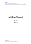
Figure 17 TA-7600 Amplifier Head labels and warnings.
2 General Information
2.1
Theory of Tapered Amplifiers
Semiconductor diodes can be used to optically amplify the output of an
external cavity diode laser (ECDL) converting milliwatts of input power into
watts of output power. One such diode is the GaAs tapered amplifier diode.
In a GaAs tapered amplifier diode, a tapered gain region of GaAs is
electrically pumped inverting the carrier population in this region. The output
of an ECDL, at a power Pseed, can then be focused into the tapered portion of
the GaAs tapered amplifier chip by way of a focusing lens. As the beam
propagates through the gain region it will experience amplification due to
stimulated emission from electron-hole recombination.
Anti-reflection
coatings on both the input and output facets of the tapered amplifier chip
prevent self-lasing and allow for the amplified beam to exit at the wide end of
the taper with a power Pout.
Sufficient seed power from the seeding ECDL is necessary to surpass the
lasing threshold of the tapered amplifier chip. In addition, for optimal
amplification the seed wavelength must match as closely as possible the
center wavelength of the gain band of the tapered amplifier diode and the seed
beam polarization must be in accord with the polarization condition of the
tapered amplifier diode. When these conditions are met the seed beam can be
optically amplified to yield nearly diffraction-limited beam quality while
preserving important spectral and spatial seed beam characteristics (single
longitudinal mode, narrow linewidth, etc.).
2.2
Getting to Know Your Tapered Amplifier System
CAUTION
There are no user serviceable parts inside the Model TA-7600-LN
and the associated Tapered Amplifier Head. Work performed by
persons not authorized by New Focus will void the warranty. For
instructions on obtaining warranty repair or service, please refer to
Section 7.
26
General Information
2.2.1
Key Product Features:
Flexible configurations
Standards models available at 767nm, 780nm, 795nm, 852nm, 915nm
Use your own seed laser or a New Focus ECDL for a complete MOPA
system
Custom wavelengths and powers available
Protections
Laser current limit and fault protection
Active seed power monitoring helps prevent self lasing that can damage
the tapered amplifier chip
Active temperature control closed-loop
Ability to turn off the output current if a fault is detected with the TEC
Over-temperature protection
TA-7600-LN Controller
Improved data presentation and system control via large display
Ergonomic adjustment knob
Integral LED pushbuttons
Autoranging power supply that can operate on 100 - 240 volt AC power
Plug & play
2.2.2
Pre-aligned FC/APC fiber input
USB and RS232 remote interface
Amplifier head recognition
Intuitive graphical user interface provided
Instrument Features
Intuitive Controls and VFD Display
Improved data presentation and system control are achieved using a large
wide viewing angle 2 row by 20 character vacuum florescent display (VFD),
ergonomic adjustment knob, and thoughtfully arranged pushbuttons, some
with integral LEDs.
General Information
2.3
27
Controller Input Power
The Model TA-7600-LN Controller has an autoranging power supply that
can operate on 100 - 240 volt AC power.
2.4
2.4.1
Specifications
Tapered Amplifier
Model Number
TA-76XX
TA-7612
TA-7612-P
TA-7613
TA-7613-P
TA-7613-H
TA-7614-P
TA-7614-H
TA-7616
TA-7616-P
TA-7618
TA-76XX-X
2.4.2
Wavelength
Coverage Range, nm
350-755
755-775
755-775
775-785
775-785
779-790
787-805
787-805
825-855
825-855
910-920
920-5000
Maximum Power, mW
1 W at maximum; free space output
1W at 765 nm; free space output
0.5 W at 765 nm; fiber coupled output
1W at 780 nm; free space output
0.5 W at 780 nm; fiber coupled output
2 W at 780 nm; free space output
0.5 W at 795 nm; fiber coupled output
1.8 W at 795 nm; free space output
1 W at 850 nm; free space output
0.5 W at 850 nm; fiber coupled output
1 W at 915 nm; free space output
5 W at maximum; free space output
Typical Beam Divergence
< 2.5 mrad
Maximum Beam Spot Size (at 60 cm
from laser aperture)
2x4 mm
System Specifications
AMPLIFIER CHIP CONTROLLER
Current Control (Constant Current Mode)
Control Range
0 to 5 A
Compliance Voltage
1 to 5V
Laser Driver Output Power
Resolution
Resolution-Display
max 25W
100 uA
1 mA
28
General Information
TEC Driver
Output Current
Compliance Voltage
TEC Driver Output Power
2.4.3
0 to 4.3A
0 to 4.5V
max 19.35W
General Specifications
Environmental Specifications
Voltage Requirements
Power Requirements
Chassis Ground
Size (H x W x D) [in. (mm)]
Mainframe Weight [lb (kg)]
Operating Temperature
100-240 VAC, 50-60Hz
MAX POWER = 105 Watts
4 mm banana jack
3.48 (88.4) x 14.0 (355.6) x 16.51 (419.4)
17.9 (8.1)
10ºC to 40ºC
(<90% humidity non-condensing)
Storage Temperature
0ºC to + 50ºC
(<90% humidity non-condensing)
Relative Humidity, Storage
Altitude
Installation Category
Pollution Degree
Use Location
<90% humidity non-condensing
<2000 meters (6550 feet)
I
2
Indoor use only
The Model TA-7600-LN Tapered Amplifier Controller and Tapered
Amplifier Head were designed to operate in a controlled electromagnetic
environment. While they will not be damaged by operation in an industrial
electromagnetic environment, as defined in EN61326-1:2013, such operation
may not yield optimal performance. For this reason, New Focus does not
recommend operation of these devices in close proximity to mobile
telephones, hand-held radio transmitters, and similar devices.
3 Getting Started
3.1
Unpacking and Handling
It is recommended that the Model TA-7600-LN Tapered Amplifier Controller
and the Tapered Amplifier Head be unpacked in a lab environment or work
site. Unpack the system carefully; small parts are included with the
instrument. Inspect the box carefully for loose parts. Save the packaging
material in case you need to ship your equipment in the future.
3.2
Inspection for Damage
The Model TA-7600-LN Tapered Amplifier Controller and the associated
amplifier head are carefully packaged at the factory to minimize the
possibility of damage during shipping. Inspect the box for external signs of
damage or improper handling. Inspect the contents for damage. If there is
visible damage to the instrument upon receipt, inform the shipping company
and New Focus immediately. Carefully open the box and save the shipping
material for later use.
WARNING
Do not attempt to operate this equipment if there is evidence of shipping
damage or you suspect the unit is damaged. Damaged equipment may
present additional hazards to you. Contact New Focus technical
support for advice before attempting to plug in and operate damaged
equipment.
CAUTION
The user is advised to save the packaging material in case the unit has to
be shipped to a different location. The packaging material is specially
designed to protect the unit during shipping.
30
Getting Started
3.3
Parts List
The following is a list of parts included with the Model TA-7600 System
1. TA-7600-LN Tapered Amplifier Controller and its accessory items.
2. 90035117 Cable
3. TA-76xx Tapered Amplifier Head
The following is a list of parts included with the Model TA-7600-LN
Tapered Amplifier Controller:
1. USB Flash drive with Software Drivers and Utilities, User’s Manual,
Start-Up Guide.
2. IEC320 AC line cord with a NEMA 5-15P
3. USB Cable for connecting the Tapered Amplifier to a computer.
If you are missing any parts or have questions about the parts you have
received, please contact New Focus.
3.4
Choosing and Preparing a Suitable Work Surface
The Model TA-7600-LN and the Tapered Amplifier Head may be placed on
any reasonably firm table or bench during operation.
3.5
Optical Requirements
Three seed laser requirements must be met for amplification: laser
wavelength, power, and FC/APC PM single mode fiber coupled input. The
seed laser must be at or near the specified center wavelength of the TA to
achieve specified amplification output power. The seed laser must be ≥ 10
mW. The TA-7600 system has a safety feature that limits the TA current if
the input power is lower than 10 mW. This is to protect the tapered amplifier
chip and to ensure system performance. While not recommended, the
minimum input power can be reset by the user via computer interface.
Contact New Focus for further information. The seed must be fiber coupled
with an FC/APC PM single mode fiber. Contact New Focus or your local
representative should you need further information on seeding requirements.
Getting Started
3.6
31
Electrical Requirements
Before attempting to power up the unit for the first time, the following
precautions must be followed:
WARNING
To avoid electric shock, connect the instrument to properly earthgrounded, 3-prong receptacles only. Failure to observe this precaution
can result in severe injury.
WARNING
The TA-7600-LN Tapered Amplifier Controller is supplied with a
detachable power cord. Do not replace this cord with an inadequately
rated cord.
Have a qualified electrician verify the wall socket that will be used is
properly polarized and properly grounded.
Provide adequate distance between the Models TA-7600-LN, and the
amplifier head, and adjacent walls for ventilation purposes. Do not let
any other equipment blow hot air towards the devices. Verify that correct
rated fuses are installed according to the fuse marking on the rear panel.
The unit has temperature sensors. If the unit overheats it will generate an
error message and stop operation to protect itself until the user takes the
necessary steps to lower the temperature.
3.7
Controller Power Supplies
AC power is supplied through the rear panel power entry module connector
that provides in-line transient protection and RF filtering. The power entry
module also contains the instrument’s fuses.
The fuses are accessed by opening the power entry module using a flatbladed screwdriver. The AC line cord must first be removed before the
power entry module can be opened. Verify that the correct value fuses are
installed in the power entry module.
WARNING
To avoid electric shock, connect the instrument to properly earthgrounded receptacles only. Failure to observe these precautions can
result in fire, severe injury or death.
32
Getting Started
WARNING
To avoid electric shock, the appropriate fuses for the AC input power
voltage must be installed in the instrument. Only qualified service
personnel should replace fuses. Failure to observe these precautions can
result in fire, severe injury or death.
3.8
Quick Start
This section outlines the basic steps needed to start using your Tapered
Amplifier, including a brief setup and getting started guide. It assumes that
you have read the earlier sections regarding safety and AC input power
setting. For more detailed information on how to operate the instrument, refer
to Chapter 4 System Operation.
WARNING
The safety of any system incorporating the equipment is the
responsibility of the assembler of the system.
3.8.1
Connecting the Amplifier Components
Mount the amplifier head: The amplifier head is shipped with a mounting
bracket already attached. This bracket also serves as a heatsink to avoid
overheating the amplifier head. Mount the amplifier head/bracket in a stable
position with the output aperture pointing towards an appropriate beam
block. Output-beam height is two inches for the free-space models.
Position the controller: Position the controller within a cable length of the
amplifier head (about five feet). The controller keyswitch should be off (fully
counter-clockwise). Be careful position the controller in such a way that it
will be easy to access the on/off switch on the rear of the device as well as
the key switch on the front. Also position the controller in such a way that it
is easy to remove the head plug cable.
Connect the Model TA-7600-LN Tapered Amplifier Controller to the
Tapered Amplifier Head using the NPI101209 cable. Secure the screw locks
on the connectors at both ends of the cable.
Getting Started
33
WARNING
Use only New Focus Model Number NPI101209 cable, or New Focus
approved alternative, to connect the TA-7600-LN Tapered Amplifier
Controller to a TA-76xx Series Amplifier Head.
WARNING
Do not disconnect the cable between the Model TA-7600-LN Tapered
Amplifier Controller and the Amplifier Head while the Model TA-7600LN Tapered Amplifier Controller is powered up.
WARNING
Secure the connector screwlocks at both ends of the cable between the
Model TA-7600-LN and the Tapered Amplifier Head.
3.8.2
Grounding and Powering the Laser System
Verify that the proper fuses are installed. See Section 3.7, above, for details.
Connect the binding post on the rear of the chassis to earth ground. While
the protective ground wire within the MAINS power cord will provide
adequate safety protection, when connected to a properly earth-grounded
receptacle, the system noise performance may be improved if this additional
connection is made to the rear of the chassis.
WARNING
To avoid electric shock, connect the instrument to properly earthgrounded receptacles only. Failure to observe these precautions can
result in fire, severe injury or death.
WARNING
To avoid electric shock, the appropriate fuses for the AC input power
voltage must be installed in the instrument. Only qualified service
personnel should replace fuses. Failure to observe these precautions can
result in fire, severe injury or death.
3.8.3
Seeding the Amplifier
Ensure that the optical seeding requirements are met (refer to Section 3.5).
Connect the seed laser to the amplifier via the FC/APC connector on the
input side of the amplifier. Make sure that the seed laser polarization is
34
Getting Started
aligned with the slow axis of the fiber (in line with the key of the FC/APC
connector.) A green INPUT POWER LED on the controller front panel
indicates adequate input seed power. If the INPUT POWER LED is red,
seeding power is too low and the amplifier current will not turn on.
No further alignment of the seed laser is necessary.
3.8.4
Turning the Amplifier ON
Turn lockout keyswitch to “I” position to power on the unit.
Press CURRENT ON/OFF button. The LED in the button will flash for at
least 3 seconds and then stay ON. The actual amplifier diode current will
quickly ramp up to the specified setpoint.
Turn the knob control to set the desired Current set point. If Constant Power
mode is desired, allow the system time to stabilize (on the order of minutes),
then press the Power Lock button. The power level can be adjusted in
Constant Power mode by turning the knob. Allow the system time (on the
order of minutes) to stabilize after changing the Current set point or Power
set point in either mode. Note that Constant Power mode operation is limited
to 1-99% of the total tapered amplifier current range.
3.8.5
Turning the Amplifier OFF
To minimize the risk of power surges damaging the amplifier diode and to
preserve the lifetime of the diode, push the CURRENT ON/OFF button to
turn OFF the amplifier when it is not in use (the LED on the button will turn
off) and before shutting down the system. Turn the front panel keyswitch to
“O” position to shut down the entire system.
3.8.6
Software Installation
For instructions on how to install the software provided with the Tapered
Amplifier, please refer to TLB-7600 ReadMe.pdf file. You need to have a
PDF reader to view its contents.
4 System Operation
4.1
4.1.1
Description of Tapered Amplifier System
Tapered Amplifier Head
The New Focus TA-7600 is designed to amplify coherent laser radiation in
the near infrared spectrum. Fiber-coupled seed radiation is amplified by up to
20 dB (100 times) while substantially retaining the spectral and noise
characteristics of the seed. The TA-76xx can provide up to 2 W, of coherent
radiation in the region of 755 – 920 nm.
A key feature of the TA-7600 tapered amplifier head is the FC/APC optical
input fiber connection which is standard with all New Focus tapered
amplifiers. This allows the seed laser to be coupled into an internal fiber that
has been carefully prealigned to the tapered amplifier diode. This prealigned
internal fiber ensures reliable and trouble-free user alignment. The amplified
laser output can be fiber coupled or free space. A 35 dB isolator at the output
comes standard with every amplifier.
Thermal isolation of the laser head is achieved by enclosing the tapered
amplifier diode block with thermally insulating foam. In addition, the base of
the tapered amplifier housing acts as a heat sink. An on-board temperature
sensor is used to monitor the diode temperature and provides the input to the
temperature control closed-loop. A Peltier type thermoelectric cooler (TEC) is
used maintain a constant tapered amplifier temperature.
There are two photodiodes in the tapered amplifier head that monitors input
seed power and output amplified power. Beamsplitters are used to pick off a
small percentage of the input and output beams and direct them to the
photodiodes. The measured current of these photodiodes are calibrated at the
factory. The purpose of the input photodiode is to ensure sufficient seed
power and is a safety feature of the TA-7600 system. If the seed power is less
than 10 mW, the user will not be able to turn on the tapered amplifier current,
preventing damage as well as self-lasing of the amplifier. The output
photodiode provides feedback for Constant Power mode.
36
System Operation
4.1.2
Tapered Amplifier Controller
The tapered amplifier is controlled using the TA-7600-LN Tapered Amplifier
Controller. To ensure best performance, each tapered amplifier head is
calibrated with its corresponding controller. The control unit works in both
manual and remotely programmed modes and is compatible with USB and
RS232 interfaces. The TA-7600-LN’s front panel multi-line display shows
important operating parameters including amplifier current and input and
output power.
The job of the Tapered Amplifier Controller is to provide a stable, low-noise
power source for the diode amplifier, set the temperature in the amplifier
head, and provide readouts of all relevant amplifier parameters. Conceptually,
the circuitry inside the Tapered Amplifier Controller is built in two layers:
analog and digital. The analog layer incorporates low-noise design for
temperature and current control. The digital layer includes all the readouts and
circuits to set various operating point parameters. This layer acts as an
interface between the user (or the user’s computer) and the analog layer.
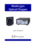
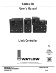
Figure 18 Tapered Amplifier Block Diagram.
The analog layer consists of four modules: current control, temperature
control, and piezoelectric transducer (PZT) driver (which controls wavelength
fine-tuning)
System Operation
37
The digital layer includes a Digital Signal Processor (DSP) and user interface
circuitry. There is a digital circuit in the amplifier head that contains
information specific to each head, such as the optimal temperature, current
settings, and the laser head serial number.
The current driver is a low-noise, analog, DC-current supply which provides
up to several A of current to the amplifier diode. The AC ripple in the output
is sub μA RMS.
The temperature driver controls the amplifier head’s internal temperature by
supplying current to thermoelectric (Peltier) elements in the amplifier head. A
DSP is used to perform PID feedback control for each element. In this way,
the tapered amplifier gain element temperature and the surrounding
environment are stabilized to within plus or minus 10 millikelvin.
The DSP based digital board controls all of the other modules, runs the digital
displays, and provides USB interfacing capability. It also communicates with
the circuit board in the amplifier head to determine what kind of amplifier
head it is.
WARNING
Before powering up or operating the Model TA-7600-LN Tapered
Amplifier Controller, please read and understand all of Section 1.
4.2
Using the Front Panel
The front panel of the Model TA-7600-LN Tapered Amplifier Controller is
designed for easy operation. It has various distinct areas, each with a specific
set of related functions, and control knobs, as shown in Figure 19 below.
38
System Operation
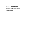
Figure 19 Front Panel Layout
Make sure the Tapered Amplifier Controller is plugged into a 3-pronged
receptacle and your amplifier head cable is plugged into the both the back of
the Tapered Amplifier Controller and the Tapered Amplifier Head. Connect
the output of the Tapered Amplifier Head to a safely-terminated fiber-optic
cable.
Turn on the AC power using the front panel keyswitch. On startup, the
amplifier-head serial numbers, optimum diode parameter settings and other
pertinent operating information stored in an EEPROM in the amplifier head
are uploaded to the Tapered Amplifier Controller. The alphanumeric display
will show the model number, and the Tapered Amplifier Controller software
revision number. After a few seconds, the display will become active.
About 30 minutes of warm-up time is recommended for best performance.
Allow further warm-up time (on the order of minutes) after setting or
changing the current or power.
The keyswitch is the “ON/OFF” switch for the whole system including both
the controller and the amplifier head. The CURRENT ON/OFF button
controls the laser output from the amplifier head. When you push the
CURRENT ON/OFF button, it flashes for a 6-second safety delay (default
value) and then lights up to indicate that current is flowing through the diode
in the amplifier head unit. This allows you to set up all the desired operating
parameters with the AC Power on, but while the amplifier head is not
generating light.
System Operation
4.2.1
39
Setting the Tapered Amplifier Gain Current
To set the desired Current level turn the knob control below the display
screen. The system is set so that the maximum drive current is below the
damage threshold and self-lasing threshold. It is not possible for the end-user
to increase the drive current beyond the factory set limit. Following initial 30
minute warm-up, allow additional warm-up time (order of minutes) for the
system to stabilize after changing the Current or Power set point.
4.2.2
Tapered Amplifier Current Limit Protection
One of the parameters stored in the amplifier head’s internal memory is the
Tapered Amplifier Maximum Current Limit.
Normal operation occurs only when the tapered amplifier current set point
does not exceed the maximum limit. To protect the tapered amplifier from
being inadvertently driven over the limit, TA-7600-LN employs two over-thelimit conditions: SOFT LIMIT and HARD LIMIT.
If the current limit is exceeded by more than 2 mA, the system enters the
SOFT LIMIT condition, in which the set point is limited as set by the limit
level. When the user decreases the laser current level below the limit the
system returns to normal operation.
If the current limit is exceeded by more than 7 mA, the system enters the
HARD LIMIT condition, in which the unit will shut the laser immediately and
display an error message. This protection feature avoids transients from being
sent to the tapered amplifier. To return to normal operation the user needs to
reduce the laser current level below the limit and then turn the current ON
from the CURRENT ON/OFF button.
4.3
Menu Section
In addition to showing status parameters on the display, the Menu section of
the front panel enables the User to view and change settings.
4.3.1
Control Knob
The TA-7600-LN control knob can be used to change values of the parameter
shown in the area of the display directly above the knob.
The control knob can also be used to set the value of the Current or Power
depending whether in constant current or Power Lock mode, respectively.
The knob has an acceleration algorithm that causes the rate of change of the
value to increase as the knob is turned faster. Turning slowly allows for fine
adjustment at the smallest displayed digit.
40
System Operation
4.3.2
Display Elements
The Model TA-7600-LN Tapered Amplifier Controller uses a character
display to depict information about the current state of the system. The
display screens shown by the instrument can be classified as follows: title
screen, laser head information screen, main Setup screen, parameter setup
screen and error message screen.
4.3.3
Title Screen
The title screen is displayed for a few seconds every time the instrument is
powered ON. A sample title screen is shown in Figure 20.
New Focus
TA-7600-LN
Figure 20 A sample title screen.
4.3.4
Instrument Firmware Version Screen
Immediately after the title screen, the next screen shows the instrument
firmware version and date.
TA-7600-LN
Fwr: v1.8 12/09/13
Figure 21 A sample Firmware Instrument Version Screen.
4.3.5
Amplifier Head Startup Information Screen
The Amplifier Head Information screen is displayed for a few seconds after
the Instrument Firmware Version screen every time the instrument is powered
ON. This screen is used to display the model and serial number of the laser
head connected to the Tapered Amplifier Controller. A sample screen is
shown in Figure 22.
System Operation
41
TA-7613
S/N = TA-0005
Figure 22 A sample Amplifier Head Information screen.
4.3.6
Main Screen
The Main screen is displayed after the Amplifier Head Information screen.
When the unit is turned ON for the first time the main screen will show ‘0.0
mA’ laser current. The User can then set the desired current value using the
Control Knob. The value, in mA, will be displayed on the top line of the
Main Screen. The bottom line will reflect this value relative to the maximum
diode current, as a horizontal bar. Figure 23 shows what the Main Screen will
look like on startup.
Current = 0.0mA
Min ___________ Max
Figure 23 A sample Main Screen.
4.3.7
Information Screen
The Information screen is displayed by pressing the button labeled “i” on the
top right corner of the controller front panel. The knob is used to scroll down
the Information list. The values reported for S/N, Date of manufacture, ON
Time, and Tot Time refer to the tapered amplifier head that is connected to the
controller and cannot be changed by the user. ON Time is the duration that
the TA current has been on and resets when the current is turned off. Tot
Time is the total number of hours the current has been on since the
manufacture date. The user is allowed to enable or disable the front panel
knob, a useful feature to prevent unintentional adjustment of the TA current.
To disable the knob, scroll down the menu until the diamond is located next to
Knob Enable then press the “i” button. The screen will return to Main Screen
and “Knob Disabled” will appear on the Main Screen to indicated the knob is
disabled. In order to enable the knob, press the “i” button, scroll down to
Knob Enable and then press the “i” button. Powering down the controller will
also reset the Knob Enable to ON. The Information screen can be excited by
pressing the “i” button. Avoid changing the Knob Enable setting by ensuring
the diamond is not next to Knob Enable when exiting the Information Screen.
42
System Operation
Tot Time = 0035.0hr
♦ Knob Enable = ON
Figure 24 A sample Information Screen.
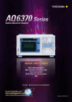
4.4
Rear Panel
The Model TA-7600-LN rear panel has various dedicated input and output
connectors, as well as important labeling, as shown in Figure 24.
Model,
Serial #,
WEEE
symbol
CE and
RoHS
labels
Fuse
label
Interlock
input
RS-232
interface
USB
interface
Tapered
Amplifier
Control I/O
Chassis
ground
Max
power
Figure 25 Rear panel. (Label IEC 320 as it’s referred to in text.)
System Operation
4.4.1
43
USB Interface
The TA-7600-LN is designed to communicate with standard USB host
interfaces. The connector on the rear panel is a standard USB-B (full-size,
device).
4.4.2
RS-232 Serial Interface
The TA-7600-LN can also communicate via a standard RS-232 serial
interface. The connector on the rear panel is a standard female 9-pin Dsub.
Note that the built-in serial port on a PC is a DTE device. A straight-through
cable is used to connect a DTE device (PC) to a DCE device (e.g., TA-7600LN). The TXD-RXD and RTS-CTS pins are not cross-connected in this case,
hence the term straight through cable.
4.4.3
Chassis Ground
This 4 mm banana jack is connected to chassis ground. It is intended to be
used as an additional earth ground connection for the Model TA-7600-LN’s
enclosure.
4.4.4
AC Power Cord
The Model TA-7600-LN will operate on either 50 or 60 Hz mains power. The
instrument has an auto-ranging power supply and will operate with a nominal
AC input voltage of 100 to 240 VAC.
The line cord supplied with each unit should be plugged only into a properly
grounded receptacle to prevent electrical shock in the event of an internal
short circuit to the metal cabinet. The detachable line cord should be
connected to the IEC320 connector on the power entry module.
44
System Operation
4.4.5
Fuses
The correct fuses must be installed into the fuse holder that is part of the AC
power entry module. Please check the fuse label on the rear panel, before
installing new fuses, see Figure 25.
WARNING
To avoid electric shock, the appropriate fuses for the AC input power
voltage must be installed in the instrument. Only qualified service
personnel should replace fuses. Failure to observe these precautions can
result in fire, severe injury or death.
5
5.1
Computer Interfacing
Introduction
The Model TA-7600-LN Tapered Amplifier Controller has USB and RS-232
interfaces to receive commands from and send responses to a host PC. The
commands supported by the Tapered Amplifier Controller can be divided
into two categories: “set commands” that cause it to take a desired action,
and “query commands” that cause it to return a stored value.
The query commands are used to query the state of the controller and must
end with a question mark (?). Set commands, on the other hand, are used to
configure/setup the Tapered Amplifier for a desired mode of operation.
These commands take at least one parameter. If the Tapered Amplifier
Controller executes the command successfully, it responds with an “OK”
string. Otherwise, it returns an error message. If an error is returned, it is
recommended that the User read the error before issuing any additional
commands. The subsequent sections in this chapter detail the communication
protocols supported by the instrument.
5.2
GUI Application
An intuitive GUI is provided with the TA-76xx Tapered Amplifier system
and can be easily installed. The files and installation guide can be found on
the USB flash drive provided with the TA system. The GUI allows the user
to perform all of the operations available on the TA 7600-LN Controller front
panel.
5.3
Computer Interface Terminology
Listed below are the key abbreviations and concepts used in the command
reference section of this manual.
5.3.1
<…> Delimiting Punctuation
For the purposes of this manual, any string enclosed by <…> is considered to
be a command, a string, or a numerical argument. The punctuation <…> will
be used to symbolize the typographic limits of the command, string or
argument in question.
46
Computer Interfacing
5.3.2
<CR> Carriage Return
The ASCII encoded byte 13 in decimal. (0D hex)
5.3.3
<LF> Line Feed
The ASCII encoded byte 10 in decimal. (0A hex)
5.3.4
(;) Semicolons
Semicolons are used to separate commands within a single transmission
(concatenation).
5.3.5
Command Termination
All the commands sent to the driver must be terminated by a <CR><LF>
sequence.
5.3.6
Response Termination
All the responses from the driver are terminated by a <CR><LF> sequence.
5.4
Tapered Amplifier Operation Mode
The Tapered Amplifier supports two modes of operation: LOCAL and
REMOTE. The Tapered Amplifier will be in LOCAL mode, by default,
following a power reset. In this mode, all the main setpoints and system
parameters can be adjusted by turning the control knob on front panel of the
Tapered Amplifier Controller. Output can be turned ON and OFF by
pressing the CURRENT ON/OFF button. Please refer to Chapter 4: System
Operation for a detailed description on how to accomplish these tasks. When
the Tapered Amplifier Controller is in REMOTE mode, knob control is
disabled; setpoints and other settings can be adjusted only by issuing
appropriate commands from a host PC.
The Tapered Amplifier Controller can be put into REMOTE mode by issuing
the command “SYSTem:MCONtrol REM”. It can be put back in LOCAL
mode by issuing “SYSTem:MCONtrol LOC” command.
5.5
USB Communication
The instrument is designed to communicate with a host PC via a standard
USB interface. Before connecting the instrument to the USB interface the
User should install the New Focus Tapered Amplifier application included in
the software CD that accompanies the tapered amplifier. The application
automatically installs the right USB drivers. The User can communicate
with the tapered amplifier through this interface by using the application or
by developing software in the user’s preferred programming language. The
software CD contains communication drivers and example programs in
LabVIEW and C#.NET.
Computer Interfacing
5.6
47
RS-232 Communication
The instrument is designed to communicate with a host PC via RS-232
communication interface. The pin out of the 9-pin D-sub connector located
on the rear panel of the Tapered Amplifier is designed to interface directly
with an IBM-compatible PC using a straight-through cable.
To communicate with the instrument, the host PC’s RS-232 settings must be
configured as follows: 8 data bits, no parity checking, 1 stop bit, and no
hardware handshake. The Tapered Amplifier can support baud rates between
1200 and 57600 bps; the default baud rate is 19200 bps.
Setting the Baud Rate for RS-232
1. Press the Menu button and scroll down to System Params menu. Press
Enter button to see this menu. The first menu item is Baud Rate.
2. Turn the right-knob to select desired baud rate. Turn the knob clockwise
to increase the value, counter-clockwise to decrease the value. Available
baud rates are 1200, 2400, 4800, 9600, 19200, 38400, and 57600.
3. Press the Back button to exit the System Params menu.
5.7
5.7.1
Commands Summary
Conventions
There are two types of device commands: commands that cause the
instrument to take a desired action, and queries that return a stored value or
state of the instrument. Queries must end with a question mark (?), while
commands may require parameter(s) to follow:
SOURce:CURRent:DIODe 60.00
For example, the value “60.00” in the command SOURce:CURRent:DIODe
60.00 sets the diode current setpoint to 60.00 mA. The command/query
MUST contain all of the letters shown in upper-case; lower-case letters in the
commands are optional, and may be used for clarity.
The commands may be sent to the instrument in either upper or lower case or
in any combination. For example, the following commands are equal:
SOURce:CURRent:DIODe 60.00
SOUR:CURR:DIOD 60.00
source:current:diode 60.00
Source:Current:Diode 60.00
48
Computer Interfacing
COMMAND TERMINATION:
All commands sent to the Tapered Amplifier must be terminated by
<Carriage Return><Line Feed>.characters. All responses sent out by the
Tapered Amplifier are terminated by the same characters.
5.7.2
Types of Commands
There are five general types of commands: Standard Commands, Output
Commands, Sense Commands, Source Command, and System Commands.
Standard Commands allow you to get information about the Tapered
Amplifier, and to set Tapered Amplifier-specific parameters such as beeper,
front panel etc. System Commands allow users to query laser, and any
system-level information.
Output Commands are used to turn ON/OFF various outputs that affect laser
performance. They can be used to query the state of the output also.
Source Commands are used to set/query laser operating parameters. Queries
return the value of various Tapered Amplifier set points.
Sense Commands return the value of various laser operating conditions.
Sense Commands read actual voltages, currents, and temperatures; the value
returned is the same as that seen on the Tapered Amplifier front panel at the
time the command is executed.
The next section has an index of all the possible computer control commands.
Then, the pages that follow the index of commands give detailed information
about each command, including a description of the command and examples
of how the command is used.
5.7.3
Index of Commands
Standard Commands
Syntax
Description
*IDN?
Identification string query
*RCL
Recall Tapered Amplifier settings
*RST
Reset the Tapered Amplifier
*SAV
Save Tapered Amplifier settings
BEEP
BEEP?
Set Tapered Amplifier beeper status
Query Tapered Amplifier beeper
status
Set Tapered Amplifier front panel
state
LOCKOUT
Computer Interfacing
LOCKOUT?
ONDELAY
ONDELAY?
49
Query Tapered Amplifier front
panel state
Set amplifier output ON delay
Query amplifier output ON delay
Output Commands
Syntax
Description
OUTPut:STATe
OUTPut:STATe?
Set amplifier output state
Query amplifier output state
Sense Commands
Syntax
Description
SENSe:CURRent:DIODe?
SENSe:POWer:DIODe?
SENSe:POWer:INPUT?
SENSe:TEMPerature:TEC?
Sense diode current
Sense output power
Sense input power
Sense TEC (diode) temperature
Source Commands
Syntax
Description
SOURce:CPower
Set constant current or constant
power mode
Returns mode of operation (constant
power or constant current)
Set amplifier diode current setpoint
Query amplifier diode current
setpoint
Set amplifier diode power setpoint
Query amplifier diode power
setpoint
SOURce:CPower?
SOURce:CURRent:DIODe
SOURce:CURRent:DIODe?
SOURce:POWer:DIODe
SOURce:POWer:DIODe?
System Commands
Syntax
Description
SYSTem:BAUDRATE
SYSTem:BAUDRATE?
SYSTem:ENTIME?
SYSTem:MCONtrol
Set RS-232 baud rate
Query RS-232 baud rate
Query Tapered amplifier usage time
Set Tapered Amplifier operation
mode (remote or local)
Query Tapered Amplifier operation
mode (remote or local)
Query laser model number
Query laser serial number
Query laser revision number
Query laser calibration date
Query laser wavelength
Query laser condition register
Query minimum input and
maximum output power levels
SYSTem:MCONtrol?
SYSTem:LASer:MODEL?
SYSTem:LASer:SN?
SYSTem:LASer:REV?
SYSTem:LASer:CALDATE?
SYSTem:LASer:WAVElength?
SYSTem:LASer:CONDition?
SYSTem:LASer:POWer?
50
Computer Interfacing
*IDN?
Description
Identification string query.
Syntax
*IDN?
Remarks
This query will cause the instrument to return an identification string.
Model
Name
Firmware
Version #
Firmware
Date
Tapered
Amplifier
Serial #
New_Focus XXXX vYYY mm/dd/yy, SNZZZZ
*RCL
Description
Recall command.
Syntax
*RCL Bin
Argument
Value
Description
Bin
0
1 to 5
Restores factory default settings
Restores settings saved in specified bin
Remarks
This command restores the instrument to the setup states saved in instrument’s nonvolatile flash memory. The parameters that can be restored are:
1. Beeper enable state
2. Dial (rotary knob) lockout state
3. Amplifier output on-delay duration
4. RS-232 baud rate
5. Hardware configuration register setting
6. Diode current setpoint
7. Diode temperature setpoint
See Also
*RST, *SAV
*RST
Description
Reset command.
Syntax
*RST
Remarks
This command performs a soft reset of the instrument.
See Also
*RCL
*SAV
Description
Save command.
Computer Interfacing
Syntax
51
*SAV Bin
Argument
Bin
Value
2 to 5
Description
Saves current settings to specified bin
Remarks
This command stores the current state of the instrument in non-volatile flash memory.
This state is then recalled using the *RCL command. See description of *RCL command
for a list of values saved/recalled by the instrument.
See Also
*RCL
BEEP
Description
Beep command
Syntax
BEEP Value
Remarks
This command controls the instrument’s beeper. The beeper is used to signal error or
warning conditions.
If no value is specified:
The Tapered Amplifier returns “NO PARAMETER SPECIFIED”.
No other action is taken.
If the value specified is not equal to 0, 1 or 2:
The Tapered Amplifier returns “VALUE OUT OF RANGE”.
No other action is taken.
If the value is 0, 1 or 2:
See Also
The beeper state is changed per table below.
The Tapered Amplifier returns “OK”.
Argument
Value
Description
Value
0
1
2
Beeper off
Beeper on
Test beeper (100ms beep)
BEEP?
BEEP?
Description
Beep query
Syntax
BEEP?
Remarks
This query returns the enable status of the beeper.
52
Computer Interfacing
Response
beep set
See Also
Description
0
Beeper off
1
Beeper on
BEEP
LOCKOUT
Description
Lockout the instrument front panel.
Syntax
LOCKOUT Value
Remarks
This command can be used to lockout all the buttons and dial knob or just the dial knob
on the front panel.
If no value is specified:
The Tapered Amplifier returns “NO PARAMETER SPECIFIED”.
No other action is taken.
If the value specified is not equal to 0, 1 or 2:
The Tapered Amplifier returns “VALUE OUT OF RANGE”.
No other action is taken.
If the value is 0, 1 or 2:
See Also
The front panel state is changed per table below.
The Tapered Amplifier returns “OK”.
Argument
Value
Description
Value
0
1
2
Front panel buttons and dial knobs enabled
Front panel buttons and dial knobs disabled
Front panel dial knob disabled
None
LOCKOUT?
Description
Instrument front panel lockout state query.
Syntax
LOCKOUT?
Remarks
This query returns the instrument’s front panel lockout state.
Response
Description
Value
See Also
LOCKOUT
Front panel lockout state
Computer Interfacing
53
ONDELAY
Description
Amplifier turn on delay command.
Syntax
ONDELAY time
Remarks
This command controls the amplifier turn on delay. This is the amount of time between
the moment the amplifier on command is received and the moment the output is actually
energized. This setting is also used when an amplifier is commanded to turn on by
pushing the CURRENT ON/OFF button on front panel of instrument when it is in local
control mode.
If no value is specified:
The Tapered Amplifier returns “NO PARAMETER SPECIFIED”.
No other action is taken.
If the value specified is less than 6000 or greater than 60000:
The Tapered Amplifier returns “VALUE OUT OF RANGE”.
No other action is taken.
If the value is in range:
Argument
See Also
The Tapered Amplifier turn on delay is changed to desired value.
The Tapered Amplifier returns “OK”.
Value
Description
Time
Integer
Time, in milliseconds. Valid values are between 6000
and 60000
ONDELAY?
ONDELAY?
Description
Laser turn on delay query
Syntax
ONDELAY?
Remarks
This command returns the laser turn on delay time.
Response
Description
Value
See Also
Time, in milliseconds
ONDELAY
OUTPut:STATe
Description
Laser output enable command.
Syntax
OUTPut:STATe State
54
Remarks
Computer Interfacing
This command turns the laser ON or OFF. When turning the laser ON, the light above
the front panel’s LASER POWER switch will flash for six seconds (default) before the
power is turned ON. The flash time can be changed using the ONDELAY command.
If no value is specified:
The Tapered Amplifier returns “NO PARAMETER SPECIFIED”.
No other action is taken.
If the value specified is not equal to 0 or 1:
The Tapered Amplifier returns “VALUE OUT OF RANGE”.
No other action is taken.
If the value is 0 or 1:
Argument
The amplifier output is turned OFF or ON.
The Tapered Amplifier returns “OK”.
Value
Description
State
Integer
0 turns the laser OFF
1 turns the laser ON
See Also
ONDELAY?; OUTPut:STATe?
OUTPut:STATe?
Description
Amplifier output enable state query
Syntax
OUTPut:STATe?
Remarks
This command returns the amplifier output enable state.
Response
Description
Value
See Also
0
1
amplifier output OFF
amplifier output ON
ONDELAY; OUTPut:STATe
SENSe:CURRent:DIODe?
Description
Actual tapered amplifier diode current query
Syntax
SENSe:CURRent:DIODe?
Remarks
This command returns the magnitude of actual tapered amplifier diode current.
Response
Description
Value
See Also
Actual tapered amplifier diode current in milli-Amperes (mA).
SOURce:CURRent:DIODE; SOURce:CURRent:DIODE?
Computer Interfacing
55
SENSe:POWer:DIODe?
Description
Actual laser diode output power query
Syntax
SENSe:POWer:DIODe?
Remarks
This command returns the magnitude of actual tapered amplifier diode output power.
Response
Description
Value
See Also
Actual tapered amplifier diode output power in milli-Watts (mW).
SOURce:POWer:DIODE; SOURce:POWer:DIODE?
SENSe:POWer:INPUT?
Description
Actual laser diode input power query
Syntax
SENSe:POWer:INPUT?
Remarks
This command returns the magnitude of actual tapered amplifier diode input power.
Response
Description
Value
See Also
Actual tapered amplifier diode input power in milli-Watts (mW).
None
SENSe:TEMPerature:TEC?
Description
Actual tapered amplifier diode temperature query
Syntax
SENSe:TEMPerature:TEC?
Remarks
This command returns the magnitude of actual tapered amplifier diode temperature. Note
that the diode temperature is actively controlled. If the room temperature ever gets so
high that the coolers have insufficient capacity to reduce the temperature, the control loop
can become unstable and destroy the cooling elements. To prevent damage, the amplifier
is automatically shut down if the amplifier diode temperature exceeds safe limits.
Response
Description
Value
See Also
Actual tapered amplifier diode temperature in degC (oC).
SOURce:TEMPerature:TEC; SOURce:TEMPerature:TEC?
SOURce:CPower
Description
Sets mode of operation to constant current or constant power
Syntax
SOURce:CPower Value
Remarks
This command sets the Tapered Amplifier mode of operation.
Argument
Value
Description
Value
0
Sets mode to constant current
56
Computer Interfacing
1
See Also
Sets mode to constant power
SOURce:CPower?
SOURce:CPower?
Description
Queries mode of operation.
Syntax
SOURce:CPower Value
Remarks
This query returns the tapered amplifier mode of operation as constant current or constant
power.
See Also
Description
Value
Description
Value
0
1
constant current
constant power
SOURce:CPower
SOURce:CURRent:DIODe
Description
Amplifier current set.
Syntax
SOURce:CURRent:DIODe Value
Remarks
This command sets the Tapered Amplifier current setpoint.
If no value is specified:
The Tapered Amplifier returns “NO PARAMETER SPECIFIED”.
No other action is taken.
If the value specified is greater than the diode current rating:
The Tapered Amplifier returns “VALUE OUT OF RANGE”.
No other action is taken.
If the value is in range:
The Tapered Amplifier current is changed to specified value.
The Tapered Amplifier returns “OK”.
Argument
Value
Description
Value
MAX
If the string “MAX” is specified as value, the diode
current setpoint is set to the diode’s current rating
Desired tapered amplifier current in milli-Amperes (mA)
Float
See AlsoSOURce:CURRent:DIODe?
SOURce:CURRent:DIODe?
Description
Tapered amplifier current setpoint query.
Computer Interfacing
57
Syntax
SOURce:CURRent:DIODE?
Remarks
This query returns the tapered amplifier current setpoint.
Response
Description
Value
Tapered amplifier current setpoint in milli-Amperes (mA)
See AlsoSOURce:CURRent:DIODe
SOURce:POWer:DIODe
Description
Diode laser output power set.
Syntax
SOURce:POWer:DIODe Value
Remarks
This command sets the Tapered Amplifier output power setpoint.
If no value is specified:
The Tapered Amplifier returns “NO PARAMETER SPECIFIED”.
No other action is taken.
If the value specified is less than 1.0 or greater than 99.0:
The Tapered Amplifier returns “VALUE OUT OF RANGE”.
No other action is taken.
If the value is in range:
The Tapered Amplifier power is changed to specified value.
The Tapered Amplifier returns “OK”.
Argument
Value
Description
Value
MAX
If the string “MAX” is specified as value, the diode
power setpoint is set to 99%
If the string “MIN” is specified as value, the diode
power setpoint is set to 1%
Desired diode laser power in percentage of laser
amplifier’s output power rating (%)
MIN
Float
See Also
SOURce:POWer:DIODe?
SOURce:POWer:DIODe?
Description
Diode laser output power setpoint query.
Syntax
SOURce:POWer:DIODE?
Remarks
This query returns the Tapered Amplifier output power setpoint.
Response
Description
58
Computer Interfacing
Value
See Also
Tapered Amplifier power setpoint in percentage of laser amplifier’s
output power rating (%)
SOURce:POWer:DIODe
SYSTem:BAUDRATE
Description
RS-232 baud rate set
Syntax
SYSTem:BAUDRATE Value
Remarks
This command controls the instrument’s RS-232 baud rate.
If no value is specified:
The Tapered Amplifier returns “NO PARAMETER SPECIFIED”.
No other action is taken.
If the value specified is less than 0 or greater than 6:
The Tapered Amplifier returns “VALUE OUT OF RANGE”.
No other action is taken.
If the value is between 0 and 6:
See Also
The RS-232 baud rate is changed per table below.
The Tapered Amplifier returns “OK”.
Argument
Value
Description
Value
0
1
2
3
4
5
6
Baud rate = 1200 bps
Baud rate = 2400 bps
Baud rate = 4800 bps
Baud rate = 9600 bps
Baud rate = 19200 bps
Baud rate = 38400 bps
Baud rate = 57600 bps
SYSTem:BAUDRATE?
SYSTem:BAUDRATE?
Description
RS-232 baud rate query
Syntax
SYSTem:BAUDRATE?
Remarks
This query returns the RS-232 baud rate.
Response
Value
Description
0
Baud rate = 1200 bps
1
Baud rate = 2400 bps
2
Baud rate = 4800 bps
Computer Interfacing
3
4
5
6
See Also
59
Baud rate = 9600 bps
Baud rate = 19200 bps
Baud rate = 38400 bps
Baud rate = 57600 bps
SYSTem:BAUDRATE
SYSTem:ENTIME?
Description
Laser enable time query.
Syntax
SYSTem:ENTIME?
Remarks
This query returns the amount of time laser diode output has been enabled.
Response
Description
Value
See Also
Laser diode enable time in minutes (min)
OUTPut:STATe
SYSTem:MCONtrol
Description
Tapered Amplifier REMOTE/LOCAL operation mode set command.
Syntax
SYSTem:MCONtrol Mode
Remarks
This command is used to put the Tapered Amplifier in remote/local operation mode. The
Tapered Amplifier will be in LOCAL mode, by default, following a power reset. In this
mode, all the main setpoints and other system parameters can be adjusted by turning the
control knobs on front panel of the Tapered Amplifier. When it is in REMOTE mode,
knob control is disabled; setpoints and other settings can be adjusted only by issuing
appropriate commands from a host PC.
If no value is specified:
The Tapered Amplifier returns “NO PARAMETER SPECIFIED”.
No other action is taken.
If the value specified is not equal to “LOC” or “REM”:
The Tapered Amplifier returns “VALUE OUT OF RANGE”.
No other action is taken.
If the value is “LOC” or “REM”:
Argument
The Tapered Amplifier operation mode is changed to LOCAL or REMOTE mode.
The Tapered Amplifier returns “OK”.
Value
Description
Mode
String
REM sets the Tapered Amplifier to REMOTE mode
LOC sets the Tapered Amplifier to LOCAL mode
60
See Also
Computer Interfacing
SYSTem:MCONtrol?
SYSTem:MCONtrol?
Description
Tapered Amplifier REMOTE/LOCAL operation mode query
Syntax
SYSTem:MCONtrol?
Remarks
This command returns the Tapered Amplifier operation mode.
Response
Description
Value
See Also
REM
LOC
Tapered Amplifier is in REMOTE mode
Tapered Amplifier is in LOCAL mode
SYSTem:MCONtrol
SYSTem:LASer:MODEL?
Description
Laser head model number query
Syntax
SYSTem:LASer:MODEL?
Remarks
This command returns the model number of the laser head connected to the Tapered
Amplifier.
Response
Description
Value
See Also
String laser head model number
SYSTem:LASer:SN?
SYSTem:LASer:SN?
Description
Laser head serial number query
Syntax
SYSTem:LASer:SN?
Remarks
This command returns the serial number of the laser head connected to the Tapered
Amplifier.
Response
Description
Value
See Also
String laser head serial number
SYSTem:LASer:MODEL?
SYSTem:LASer:REV?
Description
Laser head revision number query
Syntax
SYSTem:LASer:REV?
Remarks
This command returns the revision number of the laser head connected to the Tapered
Amplifier.
Response
Description
Computer Interfacing
Value
See Also
61
String laser head revision number
SYSTem:LASer:SN?
SYSTem:LASer:CALDATE?
Description
Laser head calibration date query
Syntax
SYSTem:LASer:CALDATE?
Remarks
This command returns the calibration date of the laser head connected to the Tapered
Amplifier.
Response
Description
Value
See Also
String laser head calibration date
SYSTem:LASer:SN?
SYSTem:LASer:WAVElength?
Description
Laser diode wavelength query.
Syntax
SYSTem:LASer:WAVElength?
Remarks
This query returns the laser diode wavelength.
Response
Description
Value
See Also
Laser diode wavelength in nanometers (nm)
SYSTem:LASer:MODEL?
SYSTem:LASer:CONDition?
Description
Laser head condition query
Syntax
SYSTem:LASer:CONDition?
Remarks
This command returns the state of the laser head connected to the Tapered Amplifier.
Response
Description
Value
Bit #
0
1
2
3
4
Integer
A 16-bit decimal value representing the state of the laser
head connected to the Tapered Amplifier.
Value
0
1
0
1
Description
Soft limit condition not activated
Output current is soft limited
Reserved
Reserved
Reserved
Rear-panel interlock is grounded
Rear-panel interlock is floating
62
Computer Interfacing
5
0
1
6
7
8
9
10
11
0
1
0
1
0
1
12
13
0
1
14
15
Hard limit condition not activated
Output current turned OFF due to hard limit
Reserved
Reserved
Reserved
Tapered Amplifier temperature is normal
Output current turned OFF due to high Tapered Amplifier
temperature
Output current is turned OFF
Output current is turned ON
Output current ondelay expired
Output current ondelay not expired
Reserved
Amplifier head disconnected
Amplifier head connected
Reserved
Reserved
SYSTem:LASer:POWer?
Description
Laser diode input and output power threshold query.
Syntax
SYSTem:LASer:POWer?
Remarks
This query returns the minimum input and maximum output power levels of the Tapered
Amplifier.
Response
Description
Value1, Value2
See Also
Value1 is the minimum input power level in milli-Watts (mW)
Value2 is the maximum output power level in milli-Watts (mW)
SOURce:POWer:DIODe; SOURce:CPower
Computer Interfacing
This page has been intentionally left blank.
63
This page has been intentionally left blank
6 Tips and Techniques
6.1
Introduction
This section explains operational details of the Model TA-7600-LN tapered
amplifier controller and head. Application examples are provided.
6.2
Grounding a Laser Head
The TA-7600-LN Tapered Amplifier outputs are isolated from earth (chassis)
ground. Isolating the laser head case avoids damaging the device from
multiple ground loop potentials, AC transients, or static discharge. Since test
equipment probes, signal sources, and package mounts are often partially
earth grounded, it is often necessary to also bond the device case to earth
ground. It is strongly recommended that a single point ground scheme be
established, specifically at the binding post. This will help minimize noise,
transients, and ground loop hazards. Be sure to include any signal generators
in your ground circuit.
CAUTION
Only one connection to ground is accepted. Failure to do so may result
in the unit malfunction and/or damage. Be careful when connecting
other instruments to TA-7600-LN Tapered Amplifier, as they may have
their ground connected to the Earth Ground.
For example, oscilloscopes have the probe ground connected to Earth
Ground.
If you have additional questions about your earth grounding method, contact
a New Focus applications engineer.
Tips and Techniques
67
This page is intentionally left blank
7 Maintenance and Service
WARNING
Work performed by persons not authorized by Newport Corporation
will void the warranty.
7.1
Enclosure Cleaning
WARNING
Before cleaning the enclosure of the Model TA-7600-LN Tapered
Amplifier Tapered Amplifier, the AC power cord must be disconnected
from the wall socket.
The source enclosure should only be cleaned with a mild soapy water
solution applied to a damp lint-free cloth. Do not use an acetone or alcohol
solution; this will damage the finish of the enclosure.
7.2
Technical Support
Information and advice about the operation of any New Focus product is
available from our technical support engineers. For quickest response, ask for
New Focus Technical Support and know the model and serial number for
your product.
Hours: 8:00–5:00 PST, Monday through Friday (excluding holidays).
Toll Free: 1-866-NUFOCUS (1-866-683-6287)
(from the USA & Canada only)
Phone: (408) 980-4300
Support is also available by fax and email:
Fax: (408) 919-6083
Email: [email protected]
We typically respond to faxes and email within one business day.
69
7.3
Obtaining Service
The Vortex Plus Tunable Laser System has been designed to provide years of
trouble-free operation with virtually no maintenance except for ensuring that
the unit is not damaged, contaminated, or used in an unsafe manner. The TA7600-LN tapered amplifier controller and head contain no user serviceable
parts. To obtain information regarding factory service, contact New Focus or
your New Focus representative. Please have the following information
available:
1. Instrument model number (on the rear panel).
2. Instrument serial number (on rear panel or bottom of enclosure).
3. Description of the problem.
If the instrument is to be returned to New Focus, you will be given a Return
Number, which you should reference in your shipping documents. Please fill
out a copy of the service form, located on the following page, and have the
information ready when contacting Newport Corporation. Return the
completed service form with the instrument.
7.4
Warranty
New Focus, a division of Newport Corp, guarantees its lasers to be free of
defects for one year from the date of shipment or for 3000 hours of operation,
whichever comes first. This is in lieu of all other guarantees, expressed or
implied, and does not cover incidental or consequential loss. The laser head
warranty is void if the inner laser cavity box is opened.
70
Maintenance and Service
7.5
Service Form
New Focus U.S.A.
Office: 408-980-4300
FAX: 408-919-6083
Name _______________________________
Return Authorization #__________________
(Please obtain RA# prior to return of item)
Company ________________________________________________________________________
(Please obtain RA # prior to return of item)
Address ________________________________ ____________________Date _________________
Country _______________________ Phone Number ______________________________________
P.O. Number ___________________ FAX Number _______________________________________
Item(s) Being Returned:
Model # _______________________ Serial # __________________________
Description _______________________________________________________________________
Reason for return of goods (please list any specific problems):
71
This page is intentionally left blank
8 Appendix A – Error Messages
8.1 Introduction
The errors generated by the Tapered Amplifier can be retrieved by pushing
the “i” button on front-panel of the Tapered Amplifier, scrolling to “Errors”
menu, and pressing the “Enter” button. These errors can also be retrieved
remotely by issuing “ERRSTR?” command through USB or RS-232
communication interfaces. Some of these errors can be cleared by switching
the laser Tapered Amplifier OFF and then back ON. If the errors persist,
please contact New Focus for assistance.
The next section tabulates and includes a brief description of each error.
8.2 Error Description
A table listing all error codes is shown below. The second column gives the
error string assigned to the error while the third column gives a brief
description of the error.
Error
Code
Error String
Description
0
NO ERROR
No error exists in the error buffer
116
SYNTAX ERROR
This error is generated when the instrument receives a
command that cannot be processed.
Some typical causes:
a. Using ASCII characters outside of a string constant
that are not defined by the command language syntax.
b. Missing space between a set command and parameter.
c. Missing “?” character in case of query
126
WRONG NUM OF
PARAMS
This error is generated when the instrument is unable to
process a command due to a mismatch between the
number of parameters received and the number of
parameters required for the command.
201
VALUE OUT OF
RANGE
This error is generated when the instrument is unable to
process a command because the parameter value
received is out of range of the acceptable values for the
command.
73
407
TEC TEMP LIMIT
The temperature control subsystem output has been
turned OFF because the TEC temperature has exceeded
safe levels. Please allow the laser head to cool down
before turning the laser power ON.
424
TEC OVER TEMP
The temperature control subsystem output has been
turned OFF because the internal heatsink temperature
has exceeded safe levels. Please allow the unit to cool
down, and reset the Tapered Amplifier by turning it OFF
and back ON.
501
LDD INTERLOCK
FLT
The Tapered Amplifier Driver subsystem output has
been turned OFF because of remote interlock (BNC
connector on rear panel) assertion.
502
LDD CURRENT
LIMIT
The Tapered Amplifier Driver subsystem output has
been turned OFF because of actual current exceeding the
current limit set point.
524
LDD OVER TEMP
The Tapered Amplifier Driver subsystem output has
been turned OFF because the internal heatsink
temperature has exceeded safe levels. Please allow the
unit to cool down before turning the output ON again.
919
LASER
DISCONNECTED
This error is generated when user tries to turn the
Tapered Amplifier Driver subsystem output ON without
having a tapered amplifier head connected to the
controller.
920
LASER EEPROM
ERROR
This error is generated when user tries to connect an
amplifier head to the controller using an incompatible
cable.
921
LD HEAD ACCESS
OFF
This error is generated when user tries to modify select
tapered amplifier head parameters.
New Focus
Worldwide Headquarters
3635 Peterson Way
Santa Clara, CA 95054
(In U.S.): 877-835-9620
Tel: 408-980-4300
Fax: 408-919-6083
Internet: [email protected]
Visit New Focus Online at:
www.newport.com/newfocus
Newport Corporation, Irvine, California; Evry and Beaune-La-Rolande, France have all been certified
compliant with ISO 9001 by the British Standards Institution. Mountain View, California is DNV certified.
Printed in U.S.A.