1
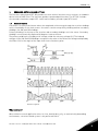
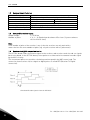
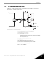
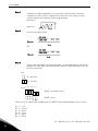
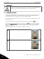
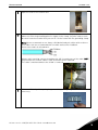
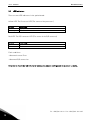
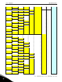
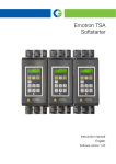
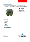
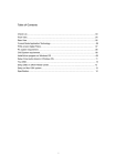
user's manual nx frequency converters resolver option board opt-bc INDEX 1. Document code: ud01039D Date: 18.2.2011 Resolver option board OPT-BC ........................................................................................... 3 1.1 1.2 1.3 1.4 1.5 2. Resolver basics ........................................................................................................................... 3 Resolver board features ............................................................................................................. 4 Compatible resolver types .......................................................................................................... 4 Resolver to digital conversion basics ......................................................................................... 4 Connectors and jumpers ............................................................................................................ 5 Installation ....................................................................................................................... 10 2.1 2.2 2.3 3. Installing the option board ........................................................................................................ 10 Installing the resolver ............................................................................................................... 12 Additional cabling instructions ................................................................................................. 12 Diagnostics ....................................................................................................................... 13 3.1 LED indicators ........................................................................................................................... 14 vacon • 3 1. RESOLVER OPTION BOARD OPT-BC The Resolver option board OPT-BC provides the user with an interface to use resolvers as feedback device to Vacon NXP Drive. The interface provides speed and position data. The OPT-BC includes also encoder simulation output (HTL -level) and secondary encoder input (HTL-level). 1.1 Resolver basics A resolver is a rotary transformer where the magnitude of the energy through the resolver windings varies sinusoidally as the shaft rotates. A resolver contains one primary winding and two secondary windings, the SIN and COS windings. Primary winding is in the rotor of the resolver and secondary windings are in the stator. Secondary windings are mechanically displaced 90 degrees from each other. The primary winding is excited by an AC voltage called the reference voltage (Vr). The induced voltages in the SIN and COS Windings are equal to the value of the Reference Voltage multiplied by the SIN or COS of the angle of the input shaft from a fixed zero point. Resolver signals Why resolvers? When a Motion control application exists in a hot, humid, dusty, oily, or mechanically demanding environment, a resolver-based system is the preferred choice. 24-hour service: +358 (0)40 8371 150 • Email: [email protected] 1 4 • vacon 1.2 Resolver board features Excitation Frequency Transformation Ratio Converter’s resolution Converter’s static accuracy Slots Encoder Simulation Output Secondary Encoder input 1.3 10/20 kHz The output voltage of the resolver has to be 1.8 to 5 Vrms 10 Bit 12 Bit +/- 2 LSB +/- 4 LSB C A, B, Z (max. pulse frequency 150kHz) HTL level A, B, Z Compatible resolver types Output voltage: Number of poles 1,7-5.0Vrms 2, 4, 6 ... 20 (Option board software V5 or later / System software version V182 or later) Note If the number of poles of the resolver is not 2, then the resolver can only work with a motor that has the same number of poles (e.g. a 6 pole resolver with a 6 pole motor). NOTE 1.4 Resolver to digital conversion basics The OPT-BC board sends the Exitation signal to the resolver, and resolver sends sin and cos signals back to the board. In the OPT-BC board, these pulses are converted to incremental encoder signal by the ASIC circuitry. The incremental pulses are used for calculating rotation speed in the NXP control card. The conversion from resolver sin/cos singals to digital pulses is called RTD (Resolver To Digital conversion). Simulated Encoder signals from the RTD ASIC Tel. +358 (0)201 2121 • Fax: +358 (0)201 2121 205 1 vacon • 5 1.5 Connectors and jumpers X21 X10 X13 X16 X3 X4 Yellow LED RED LED 1.5.1 Terminal data Connector Pins 11 to 20 are in X2 (45 connector). PIN 11 is behind PIN 1 etc. PIN 1 2 3 4 5 6 7 8 9 10 11 12 Name S4 S2 S1 S3 R1 R2 Frz+ FrzENC2_C+ ENC2_CA A\ Description SIN SIN\ COS COS\ Excitation HI Excitation LO Freeze signal HTL+ Freeze signal HTLEncoder Input Channel C Encoder Input Channel C\ Encoder Simulation Output Channel A\ Encoder Simulation Output Channel A\ 13 14 15 16 17 18 19 20 B B\ C C\ ENC2_A+ ENC2_AENC2_B+ ENC2_B- Encoder Simulation Output Channel B\ Encoder Simulation Output Channel B\ Encoder Simulation Output Channel C\ Encoder Simulation Output Channel C\ Encoder Input Channel A Encoder Input Channel A\ Encoder Input Channel B Encoder Input Channel B\ 24-hour service: +358 (0)40 8371 150 • Email: [email protected] 1 6 • vacon Jumper Settings 1. X21 (C-pulse source selection) Incremental C-pulse (Zero pulse) to control board is read from the resolver attached to the option board (Default). C-pulse is External. Read from FRZ input. 2. X10 and X13 (Gain selection) The resolver output voltage is usually told in the resolver specifications. If the specifications do not mention the output voltage, it can be calculated with the formula: Output Voltage = Input Voltage * Transformation Ratio. The resolver output voltage must be between 1,7Vrms-5,0Vrms. From 1.7Vrms to 2.6Vrms From 2.7Vrms to 5Vrms Tel. +358 (0)201 2121 • Fax: +358 (0)201 2121 205 1 vacon • 7 1.5.2 X16 and X3 / X4 (Excitation Voltage Control) The Resolver board’s Excitation voltage is configured with these jumpers. The Excitation source acts as “a constant current source”. Rf Ri Vrso COM Ri RIEXT VRef Rf Excitation voltage is calculated as follows: Vref = Exciting voltage of resolver (= Input Voltage) Iref = Exciting current of resolver Zro = input Impedance of resolver Note that this value is not the same if the excitation frequency is different than in the resolver specs. Nominal Zro is usually presented in form R + jX Vrso = Output V of RSO terminal =0.7 Vrms Rf = 56 000 ohm Fnom = Nominal Excitation Freq. (resolver Spec) Fex = Excitation Freq of the R/D converter (10 / 20 kHz) Ri = 180 000 or 400 000 ohm (jumper) Riext = 1 to 63 (7 jumpers) 24-hour service: +358 (0)40 8371 150 • Email: [email protected] 1 8 • vacon Step 1 Calculate the input impedance of the resolver. If the nominal excitation frequency for the resolver is equal to Fex, then Zro is the same as in the resolver specification and this step can be omitted. Otherwise: New Zro = R Step 2 Calculate the Riext value. OR Step 3 Get the nearest bigger value from the table 1 from attachment 1, and set the jumpers X3 & X4. If the calculated value is above 60 (Ri=180k), set the Ri Resistor to 400 k X16 Ri = 400 k Ri = 180 k 1 2 3 4 5 6 7 X3 & X4 RIEXT = 0 (don’t use!) RIEXT = 63 There are (2^7) 128 possible combinations for RIEXT value. Behind jumpers are resistors: X3 - 1 = 1 X3 - 2 = 1,66 X3 - 3 = 2,2 X3 - 4 = 3,3 X4 - 1 = 6,8 X4 - 2 = 15 Tel. +358 (0)201 2121 • Fax: +358 (0)201 2121 205 1 vacon • 9 X4 - 3 = 33 Example: X3 – 3 and X3 – 4 are connected. So RIEXT is 1+1,66+0+0+6,8+15+33= 57,46 24-hour service: +358 (0)40 8371 150 • Email: [email protected] 1 10 • vacon 2. Installation INSTALLATION Internal components and circuit boards are at high potential when the frequency converter is connected to the power source. This voltage is extremely dangerous and may cause death or severe injury if you come into contact with it. WARNING! 2.1 Installing the option board Following installation guidelines should be followed carefully to get the best performance of the system. Improper installation of the system might cause to disturbances which may in RTD conversion generate extra encoder pulses or jitter to the pulse lengths. Since the board supports large variation of resolvers, the used resolver should always be verified before installation. The option boards OPT-BC, OPT-AK and OPT-BE can only be used with Vacon NXP drives. The option boards OPT-BC and OPT-AK can be connected to slot C. The OPT-BE board can be connected to slots B, E, C or D, but sine/cos signals can only be used in slot C. If the OPT-BE board is connected to slots B, E or D, the sine/cos signals have to be disconnected using the jumpers (see chapter---) Disconnect the drive from the mains before starting the installation. A Vacon NXP frequency converter B Remove the cable cover. Tel. +358 (0)201 2121 • Fax: +358 (0)201 2121 205 2 Installation vacon • 11 C Open the cover of the control unit. D Install the option board in slot C on the control board of the frequency converter. Make sure that the grounding plate fits tightly in the clamp. Strip the cable at such distance from the terminal that you can fix it to the frame with the grounding clamp. Note! Vacon recommeds to use always shielded twisted pair cables with resolvers. Use cables that are recommended for encoder and resolver feedback. Do not mix singals in twisted pairs. Always make earthing contact throughout the full circumference of the cable (360°) Only remove the resolver cable’s outer insulation where required. The cable is weakened where the shield is removed E Make a sufficiently wide opening for your cable by cutting the grid as wide as necessary. 24-hour service: +358 (0)40 8371 150 • Email: [email protected] 2 12 • vacon F 2.2 Installation Close the cover of the control unit and the cable cover. Installing the resolver Connect the resolver after setting the jumpers. Use cable clamp in the lower part of the NXP drive to connect cable shield. Strip the cable so that the shield is exposed only from the part that is fitted to the clamp. 2.3 Additional cabling instructions The resolver and other control cables should not be in parallel with power cables (supply and motor cable). The feedback signals might also suffer from the noise coming from motor and supply cables. Use shielded symmetrical motor cables. It is recommended to connect the motor cable shield with 360° emc bushing. The motor and supply cables should not be in parallel with resolver signal cable. Tel. +358 (0)201 2121 • Fax: +358 (0)201 2121 205 2 Diagnostics 3. vacon • 13 DIAGNOSTICS The panel shows in the G7.3 that board is OPT-BC. Monitor values from 7.3.2 shows: 7.3.2.1 7.3.2.2 7.3.2.3 7.3.2.4 7.3.2.5 Resolver Freq (Hz) Resolver Speed (Rpm) Sim. Pulses/rev Encoder 2 Freq Encoder 2 Speed Parameter values from panel index 7.3.1 7.3.1.1 7.3.1.2 7.3.1.3 7.3.1.4 7.3.1.5 7.3.1.6 Invert direction Reading rate Exciting freq (10 / 20 kHz) Resolution bits(10 / 12 bits) Resolver Poles Enc 2 Pulse / Rev 7.3.2.3 Simulated pulses / rev is calculated on the basis of resolution bits(R) and resolver poles. The formula used is Simulated Pulses/rev = 2R * Resolver poles / 8. Example: Resolution bits = 12 Resolver poles = 2 Simulated Pulses/rev=212 * 2 / 8 Simulated Pulses/rev = 1024 Lower resolution is used in high speed applications (60 000 – 240 000 rpm ). In 10bit mode the resolver sends 256 pulses / revolution and in 12 bit mode 1024 pulses / revolution. The absolute position value from the resolver is mapped to AnIn 3.8. 3 is the slot of the option board. The absolute position value is from 0 to 4095 (2^12=4096). Resolver Frequency is mapped to AnIn 3.1 and Resolver speed is mapped to AnIn 3.2. 24-hour service: +358 (0)40 8371 150 • Email: [email protected] 3 14 • vacon 3.1 Diagnostics LED indicators There are two LED indicators in the option board: Yellow LED: The Processor LED (The status of the processor) LED is: OFF Blinking Meaning: Option board not activated Run State Red LED: The R/D converter LED (The status of the R/D converter) LED is: OFF ON Meaning: OK Fault Fault conditions: - Abnormal sensor Error - Abnormal R/D conversion Only way to reset the red LED, is to recalculate jumper settings and do a power up cycle. Tel. +358 (0)201 2121 • Fax: +358 (0)201 2121 205 3 Diagnostics 0 vacon • 15 = jumper not installed = jumper installed (resistor shorted) Resistor values JUMPERS X3-1 X3-2 0 1 0 0 1 1 0 0 1 1 0 0 1 1 0 0 1 1 0 0 1 1 0 0 1 1 0 0 1 1 0 1 0 1 0 0 1 1 0 0 1 1 0 0 X3-3 0 0 1,66 0 1,66 0 0 1,66 0 1,66 1,66 0 1,66 0 0 1,66 0 1,66 1,66 0 1,66 0 0 1,66 0 1,66 1,66 0 1,66 0 1,66 1,66 0 0 1,66 0 1,66 0 0 1,66 0 1,66 1,66 0 X3-4 0 0 0 2,2 0 2,2 0 2,2 0 2,2 0 2,2 0 2,2 0 2,2 0 2,2 0 2,2 0 2,2 0 2,2 0 2,2 0 2,2 0 2,2 2,2 2,2 0 0 0 2,2 0 2,2 0 2,2 0 2,2 0 2,2 X4-1 0 0 0 0 0 0 3,3 0 3,3 0 3,3 3,3 3,3 3,3 0 3,3 0 3,3 0 0 0 0 3,3 0 3,3 0 3,3 3,3 3,3 3,3 3,3 3,3 0 0 0 0 0 0 3,3 0 3,3 0 3,3 3,3 X4-2 0 0 0 0 0 0 0 0 0 0 0 0 0 0 6,8 0 6,8 0 6,8 6,8 6,8 6,8 6,8 6,8 6,8 6,8 6,8 6,8 6,8 6,8 6,8 6,8 0 0 0 0 0 0 0 0 0 0 0 0 X4-3 0 0 0 0 0 0 0 0 0 0 0 0 0 0 0 0 0 0 0 0 0 0 0 0 0 0 0 0 0 0 0 0 15 15 15 15 15 15 15 15 15 15 15 15 0 0 0 0 0 0 0 0 0 0 0 0 0 0 0 0 0 0 0 0 0 0 0 0 0 0 0 0 0 0 0 0 0 0 0 0 0 0 0 0 0 0 0 0 = = = = = = = = = = = = = = = = = = = = = = = = = = = = = = = = = = = = = = = = = = = = 0 1 1,66 2,2 2,66 3,2 3,3 3,86 4,3 4,86 4,96 5,5 5,96 6,5 6,8 7,16 7,8 8,16 8,46 9 9,46 10 10,1 10,66 11,1 11,66 11,76 12,3 12,76 13,3 13,96 14,96 15 16 16,66 17,2 17,66 18,2 18,3 18,86 19,3 19,86 19,96 20,5 24-hour service: +358 (0)40 8371 150 • Email: [email protected] 3 16 • vacon 1 1 0 0 1 1 0 0 1 1 0 0 1 1 0 0 1 1 0 1 0 1 0 0 1 1 0 0 1 1 0 0 1 1 0 0 1 1 0 0 1 1 0 0 1 1 0 0 1 Diagnostics 1,66 0 0 1,66 0 1,66 1,66 0 1,66 0 0 1,66 0 1,66 1,66 0 1,66 0 1,66 1,66 0 0 1,66 0 1,66 0 0 1,66 0 1,66 1,66 0 1,66 0 0 1,66 0 1,66 1,66 0 1,66 0 0 1,66 0 1,66 1,66 0 1,66 0 2,2 0 2,2 0 2,2 0 2,2 0 2,2 0 2,2 0 2,2 0 2,2 0 2,2 2,2 2,2 0 0 0 2,2 0 2,2 0 2,2 0 2,2 0 2,2 0 2,2 0 2,2 0 2,2 0 2,2 0 2,2 0 2,2 0 2,2 0 2,2 0 3,3 3,3 0 3,3 0 3,3 0 0 0 0 3,3 0 3,3 0 3,3 3,3 3,3 3,3 3,3 3,3 0 0 0 0 0 0 3,3 0 3,3 0 3,3 3,3 3,3 3,3 0 3,3 0 3,3 0 0 0 0 3,3 0 3,3 0 3,3 3,3 3,3 0 0 6,8 0 6,8 0 6,8 6,8 6,8 6,8 6,8 6,8 6,8 6,8 6,8 6,8 6,8 6,8 6,8 6,8 0 0 0 0 0 0 0 0 0 0 0 0 0 0 6,8 0 6,8 0 6,8 6,8 6,8 6,8 6,8 6,8 6,8 6,8 6,8 6,8 6,8 15 15 15 15 15 15 15 15 15 15 15 15 15 15 15 15 15 15 15 15 0 0 0 0 0 0 0 0 0 0 0 0 0 0 0 0 0 0 0 0 0 0 0 0 0 0 0 0 0 0 0 0 0 0 0 0 0 0 0 0 0 0 0 0 0 0 0 0 0 33 33 33 33 33 33 33 33 33 33 33 33 33 33 33 33 33 33 33 33 33 33 33 33 33 33 33 33 33 = = = = = = = = = = = = = = = = = = = = = = = = = = = = = = = = = = = = = = = = = = = = = = = = = 20,96 21,5 21,8 22,16 22,8 23,16 23,46 24 24,46 25 25,1 25,66 26,1 26,66 26,76 27,3 27,76 28,3 28,96 29,96 33 34 34,66 35,2 35,66 36,2 36,3 36,86 37,3 37,86 37,96 38,5 38,96 39,5 39,8 40,16 40,8 41,16 41,46 42 42,46 43 43,1 43,66 44,1 44,66 44,76 45,3 45,76 Tel. +358 (0)201 2121 • Fax: +358 (0)201 2121 205 3 Diagnostics 1 0 1 0 1 0 0 1 1 0 0 1 1 0 0 1 1 0 0 1 1 0 0 1 1 0 0 1 1 0 0 1 1 0 1 vacon • 17 0 1,66 1,66 0 0 1,66 0 1,66 0 0 1,66 0 1,66 1,66 0 1,66 0 0 1,66 0 1,66 1,66 0 1,66 0 0 1,66 0 1,66 1,66 0 1,66 0 1,66 1,66 2,2 2,2 2,2 0 0 0 2,2 0 2,2 0 2,2 0 2,2 0 2,2 0 2,2 0 2,2 0 2,2 0 2,2 0 2,2 0 2,2 0 2,2 0 2,2 0 2,2 2,2 2,2 3,3 3,3 3,3 0 0 0 0 0 0 3,3 0 3,3 0 3,3 3,3 3,3 3,3 0 3,3 0 3,3 0 0 0 0 3,3 0 3,3 0 3,3 3,3 3,3 3,3 3,3 3,3 6,8 6,8 6,8 0 0 0 0 0 0 0 0 0 0 0 0 0 0 6,8 0 6,8 0 6,8 6,8 6,8 6,8 6,8 6,8 6,8 6,8 6,8 6,8 6,8 6,8 6,8 6,8 0 0 0 15 15 15 15 15 15 15 15 15 15 15 15 15 15 15 15 15 15 15 15 15 15 15 15 15 15 15 15 15 15 15 15 33 33 33 33 33 33 33 33 33 33 33 33 33 33 33 33 33 33 33 33 33 33 33 33 33 33 33 33 33 33 33 33 33 33 33 = = = = = = = = = = = = = = = = = = = = = = = = = = = = = = = = = = = 46,3 46,96 47,96 48 49 49,66 50,2 50,66 51,2 51,3 51,86 52,3 52,86 52,96 53,5 53,96 54,5 54,8 55,16 55,8 56,16 56,46 57 57,46 58 58,1 58,66 59,1 59,66 59,76 60,3 60,76 61,3 61,96 62,96 Table1. RIEXT values 24-hour service: +358 (0)40 8371 150 • Email: [email protected] 3