1
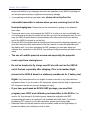
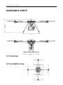
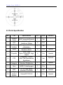
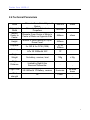
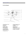
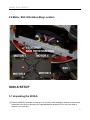
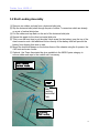
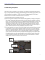
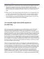
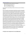
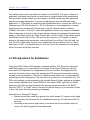
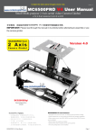
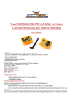
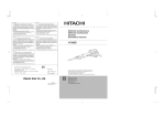
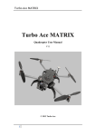
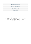
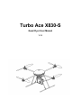
Turbo Ace X830-S
Quad Flyer User Manual
V3.8
Turbo Ace X830-S Copyright 2011 Turbo Ace
TABLE OF CONTENTS
INTRODUCTION
1.1 Welcome to the World of Quadcopters
1.2 Features
1.3 Specification
1.4 Packing List
1.5 Caution & Safety
1.6 DOA Claim
DIAGRAMS & PARTS
2.1 Profile View
2.2 Top & Bottom View
2.3 Parts Specifications
2.4 Technical Parameters
2.5 Parts Diagram
2.6 Motor & ESC & Rotation Ring Locations
X830-S SETUP
3.1 Unpacking the X830-S
3.2 Skid Landing Assembly
3.3 Mounting Propellers
3.4 Installing Heading Arch Rod & Guide Balls
3.5 Battery Requirement & Installation
ELECTRONIC SETUP & ADJUSTMENT
4.1 ESC Programming and Transmitter Calibration (For ARF)
4.2 Transmitter & Receiver Compatibility Table (For ARF Only)
4.3 Receiver, Flight Controller & Autostabilization Setup
4.4 Transmitter Settings (For ARF Only)
4.5 Transmitter Calibration and ESC programming (A Must Setup For ARF)
4.6 Transmitter Flight Control & PID adjustments (For ARF Only)
TESTING & OPERATIONS
5.1 Tie-Down Flight Test
5.2 Actual Flight Test & Training
5.3 Battery Tips
1
Turbo Ace X830-S CAMERA MOUNT SETUP
6.1 X-830-S Camera Mount Servo Control Setup
6.2 Flight Control Adjustment for Auto-Stabilization
6.3 PID Adjustment for Stabilization
MAINTENACE & REPAIR
7.1 Replacing Motors
7.2 Replacing ESC
7.3 Replacing Extension Arms
INTRODUCTION
1.1 Welcome to the World of Quadcopters
A Sputnik Moment in the making, the gravity defying Turbo Ace X830-S is poised to spark a
wide range of innovative applications in aerial video photography and surveillance. Once
dominated by manned aircraft and hot air balloons, aerial shots are often too cumbersome
and cost prohibitive. And when you need to maneuver around a subject to get different
perspectives, many videographers and photographers are increasingly gravitating towards
remote controlled helicopters. But with an additional payload of camera and associated
mounting & equipment, these larger RC helicopters are inherently too risky and extremely
difficult to pilot.
The advent of quadcopter design has revolutionized aerial video photography by offering a
safer and more stable platform. Instead of huge rotor blades, there are four smaller counter
rotating propellers controlled by a micro processor for auto stablization. Because the
camera is mounted at the center of gravity and between wide accommodating skids, no
awkward skid modification will be required. One can now envision marketing promotions,
video productions, travel video logs, nature documentation, sporting events, aerial
inspection & surveillance plus a host of other innovative applications with very minimal pilot
training.
Quadcopters are loosely classified into several categories - from toys for amusement to
complex units for professional video, science & research. Now, a new class of quadcopters
is emerging for commercial applications. The Turbo Ace X830-S is the clear leader in this
group with a list of outstanding features: Advanced PC interface (so you can update or
customize the flight controller), cutting edge auto-stabilizing mode for videographers, anti 2
Turbo Ace X830-S vibration mounts and dynamically balanced motors for high definition video production and a
host of other upgrades to improve reliability. Unlike most quadcopters, the X830-S is fully
assembled and tested for outdoor flight and it is ready to produce high quality video right out
of the box without spending even a few days to tune it. If you are starting from scratch, the
X8300-S RTF package even includes a paired transmitter that is fully programmed and
calibrated. If you already have a transmitter, all you need is an ARF package. For additional
crossing training, you can choose our optional professional Pheonix flight simulator,
possibly an easy-to-fly helicopter and mini Walkera MX400 quad. As with all Wow Hobbies
featured RC helicopters, X830-S parts, upgrades and accessories are fully supported online
and locally in the USA.
1.2 Features
•
•
•
•
•
•
•
•
•
•
•
•
•
Advanced Multi-Counter-Rotating Rotor System designed for outstanding stability &
performance
Intelligent Programmable Xaircraft FC1212A Flight Controller with PC software interface
Dual Flight Mode: Sport Flying Mode & Auto Leveling Aerial Video Mode
Advanced AHRS-S Gyro with 6-DOF Motion & MEMS Sensor Technology
Independent Core offers full compatibility with standard 2.4GHz systems
4 Dynamically Balanced C2806 Brushless Motors with outstanding power with minimal
vibration
4 Independent 35A ESCs for Outstanding Performance, Reliability & Ease of
Maintenance
Direct Drive Architecture w/o gears & servos offers reliability and ease of maintenance
Square Anti-Twist Mount Impact Resistant Propellers with low noise operations
Higher Payload suited for professional camera & video equipment
Optional Single Axis Quadriple Anti-Shock Camera Mount (available)
Optional High Capacity Batteries (5300mAh) for extended flight (available)
Optional Altitude Hold, GPS Module, FPV Integration (coming soon)
1.3 Specification
•
•
•
•
Dimensions including propellers: 892 mm × 892 mm × 262 mm
Motor: 4 x Outrunner Brushless Motors
ESC: 4 x 35A Electronic Speed Controllers
Propellers: 2 x CW and 2 x CCW, 12” With Differentiated Rotations
3
Turbo Ace X830-S •
•
•
•
•
•
•
Receiver & Transmitter Requirements: 2.4GHz 4 to 8 Channel Rx/Tx Pair
Standard Battery: LiPo 3S (11.1v) 2200mAh 20C 1P. Flight time 6-8 min
Extended Battery: LiPo 3S (11.1V) 5300mAh 45C. Flight time 20-25 min
Weight Without Battery & Camera mount: 1088g
Maximum Load (Standard): 1P 3290g
Maximum Payload: 2358g = 5.2 lbs. For proper operation and stability please limit the
payload to 2 lbs.
Wind Tolerance: Class 4
1.4 Packing List
1 x Turbo Ace X830-S Quad Flyer (Hub Chassis, 4 x Motors, ESC, Flight Controller)
• 2 x CCW Propellers (1238 Type) & 2 x CW Propellers (1238R Type)
• 1 x Skid Assembly (1 x Top Skid Assembly, 2 x Horizontal Skid Poles)
• 1 x Heading Arch Rod
• 1 x Guide Balls
• 4GB Flash Drive with test video, application software and the X830-S User Manual &
Setup Guide are contained in USB flash drive
• Programming USB-to-Micro USB Cable to link to your PC
• 1 x Velcro Battery Strip
• 1 x Nut Driver
• 1 x Allen Wrench
• Batteries: Included with RTF Package but not included with ARF Package
• Receiver: Included with RTF Package but optional on ARF Package
•
1.5 Caution & Safety
•
As the operator of the X830-S, it’s your responsibility to follow all proper procedures,
protocols and precautions to ensure the safe operation of the X830-S. The Operator
must wear safety glasses and any bystanders must be protected in a
safe area. Do not operate the X830-S in the proximity of children, pets,
cars and other vulnerable property. The owner and the operator of the X830-S
4
Turbo Ace X830-S assume all liability for any damages caused in the operation of the X830-S including but
not limited to personal injury, equipment and property damage.
•
If your package includes a transmitter radio, please do not pull on the
vulnerable transmitter’s antenna when you are removing it out of the
foam packaging box. Please remove the transmitter by pulling on the attached
•
•
neck strap.
The proper way to carry and transport the X830-S is to hold on to one or preferably two
of its extension arms near the center hub so that you don’t risk bending the arms. Do not
carry the X830-S upside down by its skid because the skid could come loose and the
rest of the X830-S may end up on the floor.
Since the X830-S propellers and skid landing are dismounted for shipping purposes, you
must first follow the setup instructions in this user manual to mount the propellers and
the landing skid. If you have purchased an ARF package you must also setup and
calibrate your transmitter to the X830-S. Any attempt to skip procedures will end in a bad
crash.
• The use of Locktite prevents screws and especially the propeller
crown caps from coming loose.
•
Do not be tempted to fly a large new RC aircraft such as the X830-S
out of the box, especially after shipping. Prior to its maiden flight,
please tie the X830-S down to a stationary workbench for 3 battery test
flights. Any crashed aircraft is not eligible for dead on arrival or any other defective
equipment claims. If you are new to RC equipment, please seek the help of experienced
RC equipment operators to prevent damage and injury.
•
If you have purchased an X830-S ARF package, you must first
program your 4 ESC and calibrate your transmitter to the X830-s. See
•
section 4.4. Any attempt to fly without proper transmitter calibration and ESC
programming will result in a crash and it will invalidate any DOA claim. If you have
purchase a RTF ready to fly unit with transmitter, please ignore these steps.
Additional Velcro should be added on both the battery strap and the flight battery to
prevent the battery from sliding from side to side.
5
Turbo Ace X830-S •
Do not plug in the X830-S flight battery when it is hooked up to a
computer. Any incorrect settings or values may trigger an accidental motor startup.
When you need to reprogram the X830-S controller and/or receiver, the power is
supplied via your PC’s USB port to your X830-S controller, which in turn supplies the
power to the receiver. There is never a need to plug in the X830-S flight battery for any
setting or receiver adjustments including transmitter calibration. Turbo Ace, its
distributors and dealers are not liable for any damages caused by the mishandling of the
X830 and it’s associated equipment.
• Operator shall use Loctite to secure all necessary screws on the X830S including but not limited to skid landing mounts and the propeller
locking nuts.
1.6 DOA Claim
Even though the main assembly with attached electronics has been assembled and tested
at the factory, it’s tested again in the USA before it’s shipped to you. If your package
includes a receiver or transmitter, the whole package will be tested as a complete set. If you
have ordered it without a transmitter, you will be required to calibrate your transmitter to the
X830-S.
• DOA (Dead on arrival) must be claimed within 24 hours of receipt.
• Report your DOA claims by email to [email protected] or simply go to
www.wowhobbies.com and click on “Contact Us”. Please include your invoice number,
products name or item number and a brief description of the problem that you are
experiencing. Technical support is only available via email.
• Please do not return any products without authorization. If you need to return a product
for service, you will need to acquire a Return Merchandise Authorization (RMA Number)
from the above email or website. If we don’t have a record of your request, your returned
product will be rejected.
• No DOA claims can be made when you pick up your X830-S because it will be test flown
live before you can take it home.
• No DOA claims can be made once the device has been crashed, including but not
limited to blade tip on the ground or any equipment failure after shipping that was not
uncovered by skipping the 3 battery test flights with the X830-S tied down to a bench.
• There is no warranty, return or exchange on RC products
6
Turbo Ace X830-S DIAGRAMS & PARTS
2.1 Profile View
2.2 Top & Bottom View
7
Turbo Ace X830-S 2.3 Parts Specification
.
No.
Part
Specifications
QTY
Units
1
Chassis
Cover
ABS Composite Material
1
Set
2
Arm
4
Pcs
3
Skid
Landing
1
Set
4
Motor
4
Pcs
Special
5
Propeller
4
Pcs
Special
6
PTZ
1
Set
7
Head
Hangers
High Strength
Aluminum Tubing
Fiberglass / Rubber /
Aluminum
C2806 KV600
Brushless Motor
1238,1238R
Nylon Composite- High
impact
Fiberglass / Carbon
Fiber Two-Dimensional
Equilibrium
Elastic Damping, Shock
Absorber Suspension
1
Set
8
Gyro
AHRS-S Heading gyro
1
Pcs
9
ESC
3S 35A high-Speed
Electronic Controller
1
Set
Special
10
Flight
Control
System
Xaircraft FC1212-S
1
Pcs
Special
Remarks
-
Optional
Special
-
8
Turbo Ace X830-S 2.4 Technical Parameters
Width
Extended
Width
Motors
Center to
Center
Height
Propeller
Battery
Single
Weight
Flight
Distance
Flight Time
Wind
strength
Diameter From Outer Edges of
Motors
Diameter From Extended
Propellers
680 mm
±3mm
885 mm
Diameter From Center of Motor to
Center of Motor on Opposite Side
580mm
Bottom of Skid Landing to Top of
Dome Cover
243mm
2 x CW & 2 x CCW (1238)
12” or
305mm
LiPo 3S 2200mAh 25C
1P
No battery, receiver, load
730g
Limited by Sight & the
Receiver/Transmitter
-
3S 2200mAh 1P Battery, receiver
8 minutes
≤4
Class
±3mm
±10g
-
No wind
hover
-
9
Turbo Ace X830-S 2.5 Parts Diagram
1 Propeller Crown Cap
2 Motor Mount
3 Propeller
4 Rubber Gasket
5 Brushless Motor
6 Mounting Beam
7 Vertical Skid Pole
8 Rubber End Cap
9 Horizontal Skid Pole
10 Chassis Cover
11 Flight Controller / Gyro
12 Optional Receiver
13 Chassis
14 Extension Arm
15 Beam Spacer
16 Battery Mounting Rods
17 CNC Center Coupling
18 Rubber T-Connector
10
Turbo Ace X830-S 2.6 Motor, ESC & Rotation Ring Location
X830-S SETUP
3.1 Unpacking the X830-S
(1) Remove all X830-S contents from the box. Do not pull on the transmitter antenna to remove the
transmitter out of the box because you might damage the antenna. Pull on the neck strap to
remove it out of the box.
11
Turbo Ace X830-S 3.2 Skid Landing Assembly
(1) Remove one rubber end cap from a horizontal skid pole.
(2) Slip the horizontal skid poles through the pair of rubber T-connectors which are already
on a pair of vertical skid poles.
(3) Put the rubber end cap back on the end of the horizontal skid pole.
(4) Repeat this again for the other horizontal skid pole.
(5) This is now the best time to put the wide Velcro strap (for the battery) over the top of the
steel connector rods. Add additional Velcro directly on the battery itself will prevent the
battery from slipping from side to side.
(6) Mount the horizontal beams on the bottom frame of the chassis using the 4 spacers, the
4 M3 nuts and some Loctite.
(7) Optional: Use Team Associated tire glue available in the X830-S parts category to
secure rubber end caps to the carbon rod if necessary.
Skid
Landing
Horizontal
Pole
12
Turbo Ace X830-S 3.3 Mounting Propellers
There are a total of 4 propellers in your package, all of which are marked with the Xaircraft
logo. 2 of the propellers are marked as 1238 counter-clock-wise (CCW) type propellers. The
other 2 propellers are marked as 1238R clock-wise (CW) type propellers. Each type of
propeller must be mounted on a specified motor on the X830-S.
(1) Unscrew and remove the propeller crown nuts.
(2) Due to the precision needed to reduce vibrasion the propellers are design to fit tightly on
the motors. Please apply light grease on the motor shaft where the propeller is going to
mount. This will enable easy removal of the propellers when replacement is needed. See
figure below, insert each type of propellers with the “XAircraft” logo facing up to each
specified motor location. Motor 1 & 3 uses 1238 (CCW) propellers and motor 2 and 4
use 1238R (CW) propellers. See the figure below and make sure they match exatly as
shown. Failure to mount the correct propeller(s) will result in a crash.
(3) It is very important to put some Loctite on the inside of each crown cap before securing it
to the propeller. Insert a small screwdriver through the top hole of the crown caps and
tighten it in a clockwise direction. When the crown cap locks and touches the propeller,
use no more than half pound of torque to lock the propeller in place. A snuggly fitted
crown cap with Loctite will prevent the propeller from disengaging from the motor shaft.
Overtightening the crown caps may damage the motor aluminum threads. Repeat this
for all 4 propellers. Important note: Every time you remove the propellers you need to
reapply some Loctite on the inside of each crown cap.
CCW
Props
Heading
Guide ball
CW
Props
13
Turbo Ace X830-S 3.4 Installing Heading Arch Rod & Guide Balls
Since the X830-S is relatively symetrical it’s often difficult if not impossible for the pilot to
see the heading (orientation) of this aircraft from a distance. By installing the heading arch
and guide ball, the pilot will be able to differentiate the front of the aircraft from the rest of
the aircraft during flight.
(1) Insert the heading carbon rod through the bottom of the motor mount hole.
(2) Shift and/or bend the heading arch to either side in order to insert it through the motor
mount holes.
3.5 Battery Requirement & Installation
(1) Standard Battery: 3-S Lipo, 11.1V, 2200mAh, 25C, 1P
(2) Extend Flight Battery: 3-S Lipo 11.1V, 5300mAh, 45C, 1P
(3) Release the wide velcro strap on the bottom of the center hub
(4) Make sure a velcro strip is added to your battery and secure it with the wide velcro strap
(5) Do no plug in the battery at this time
ELECTRONICS SETUP & ADJUSTMENT
(For ARF Only)
Please skip Section 4.1 through 4.5 if you have purchased a RTF package because all
setting are aleady complete and your X830-S and transmitter has been paired and test
flown. Unless you are familiar with the settings, any changes might override the factory’s
setting and disable the aircraft, affecting its performance and flight reliability.
14
Turbo Ace X830-S 4.1 ESC Programming and Transmitter Calibration (For ARF)
Please do not skip these steps or crash will be iminent.
Transmitter Calibration and ESC must be programmed for the X830-S purchased without
transmitter. You may skip these steps if you have purchased the X830-S with transmitter
which we have already programmed everything for you. If this is the first time you are using
your existing transmitter with your new Turbo Ace X830-S, it’s important to program all four
ESC in the X830-S as well as calibrating your transmitter to the flight controller.
ESC Programming
(1) Please skip this ESC programming step if you own a Futaba or Walkera transmitter,
however you still must calibrate your transmitter unless you have purchased a RTF unit with
a transmitter radio. For all other transmitters such as Spektrum and JR, you will need to
program the 4 ESC on the X830-S, please follow the steps below very carefully, as it will
only take a few minutes. Remove all 4 propellers from the motor for safety. This is very
important! First start by labeling the 4 ESC connectors #1 through #4 on the output side of
the FC1212-S controller (not the input side where the receiver is connected to) so they you
will be able to insert them back later to the controller in the original sequence. Next remove
all 4 labeled connectors, note it is important to remove all 4 connectors from the flight
controller FC1212-S, as it will interupt ESC end point programming. Next insert the #1
labeled ESC connector to the throttle channel of your receiver while watching for the correct
polarity, black/dark brown wires are usually on the top side of the receiver, please double
check this in your receiver manual. Turn the radio on and move throttle stick all the way up,
throttle trim must however be set to all the way down. Again, make sure all 4 propellers
have been removed for safety. Now plug in the battery to the X830-S, the ESC will make 2
beeping sound continuously until you have moved the throttle stick all the way down (Please
make sure you move the stick all the way down immediately before the 2 consecutive
beeping stops. If not, start over because the ESC was not in the programming mode.). It will
then play a series of music. You now have completed the high and low ESC end point
program for your transmitter. Disconnect the battery then remove the ESC connector #1
from the receiver. ESC #1 has already retained the end point data in its memory. Now move
the throttle stick all the way up and repeat this process for each ESC (#2 through #4) you
have labeled, by plugging it in one at a time to the throttle channel of the receiver. Your
transmitter power should remain on through out the entire process. After you have
succesfully programmed all 4 ESC, insert the connectors you have labeled in sequence
back to the OUTPUT channel 1 through 4 of your FC1212-S flight controller. The black/dark
brown wires of the connectors are closest to the edge of the flight controller.
15
Turbo Ace X830-S Transmitter Calibration
(2) Now you are ready to calibrate your transmitter to the flight controller. If you have a
Futaba or Walkera transmitter you should have skipped the ESC programming steps above
because we have already completed that for you. However every transmitter radio needs to
be calibrated unless you have purchased a transmitter with your X830-S which we have
already done the calibration for you. First, turn on your transmitter radio (Warning never
connect a battery to the X830-S unless you are flying, failure to do so will cause serious
injury as the X830-S motor may startup if an incorrect value is entered.). Connect the
provided Programming USB-to-MicroUSB cable from your PC computer’s USB port (XP or
WIN7) to MicroUSB port on the X830-S communication port (on the side panel of the X830S chassis). This cable supplies the power to both the controller and the receiver in the
X830-S, which is the reason a flight battery should never be used during programming. For
Walkera random bind radio such as the WK2801-Pro, this cable needs to be connected
within 2-3 seconds after the transmitter power is turned on so the transmitter will bind to the
receiver.
(3) Double click on the application file named Xaircraft Center software containing 2,923K
bytes located in the XAIRCRAFT CENTER V1.33 UPGRADE subfolder of the provided 4gb
USB flash drive. Wait for the control panel to open with a picture of the flight controller
FC1212-S on your PC screen.
(4) Click on the top right black tab to connect your PC computer to the X830-S flight
controller. Note the first time you connect the system, the language may initiat in Chinese.
After you have connected, you may change the language to “English” by clicking on the
lower left corner of the screen.
(5) Select submenu RC on the left column, click on the bottom tab “Calibrate” and follow
instructions to complete the procedure. The whole calibration process must be completed
with all trims centered except with the throttle trim which must be all the way down by
looking at the transmitter LCD screen. Failure to do so will likely result in a crash.
(6) Click on “Save” to save the new settings to the flash drive on your computer then click
on “Load” to load it into the FC1212-S flight controller. A common mistake is that the user
misunderstands “Save” as being saving settings to the flight controller whereas “Load” tab is
actually the one that saves the setting to the flight controller. If you don’t click the “Load” tab
the flight controller setting will not be changed.
.
16
Turbo Ace X830-S 4.2 Transmitter & Receiver Compatibility Table (For ARF Only)
The X830-S support 35MHz, 40MHz, 72MHz but prefers a 2.4GHz systems.
No.
2
3
4
5
6
7
8
9
10
Brand
Walkera
Spektrum
JR
JR
WFLY
Futaba
Futaba
Futaba
Sanwa
Hi-TEC
Transmitter
WK2801PRO
DX7
DSX7
9XII
FT06-C
FF9
6EX
10C
RD8000
Eclipse7
Receiver
RX2801PRO
AR7100
RD721
FRP06
R149DP
R146iP
92777
FRP06
17
Turbo Ace X830-S 4.3 Receiver, Flight Controller & Autostabilization Setup
(1)
Remove four screws on the dome chassis cover to open the chassis.
Remove the film to expose the adhesive on the two way tape on top of the USB linkage
circuit borad and the affix the receiver.
(3) Make sure the receiver antenna is as far away as possible and not touching the
FC1212-S flight controller board.
(4) The AHRS-S gyro on the FC1212-S flight controller board must remain free from
surrounding wires and components so its rubber shocks can operate freely. Failure to
do so will cause improper operation of the aircraft.
(5) Very important! The FC1212-S appears to be symetrical but it is not. Do not confuse the
PORT A,B,C side versus the LINK PORT side. Also it is critical to distinguish the input
and the output side of the FC1212-S. These markings are etched on the side of the
(2)
18
Turbo Ace X830-S (6)
(7)
(8)
(9)
plastic cover as “OUTPUT” for ESC connections and “INPUT” for receiver connections.
Failure to do so may damage the flight controller. Each channel connection on the
receiver much match the corresponding input channel on the flight controller.
Connect Channel #1 wire from the flight controller to the THROTTLE channel of the
receiver. Watch for polarity.
Connect Channel #2 wire from the flight controller to the ELE channel of the receiver.
Connect Channel #3 wire from the flight controller to the AILE channel of the receiver.
Connect Channel #4 wire from the flight controller to the RUDDER channel of the
receiver.
Note: Futaba receiver outputs channel are in different orders.
Setting up the X830-S to ensure a smooth flight with autostabilization
To ensure a smooth flight of your Turbo Ace X830-S, please make sure that you setup and fly the X830-S in
its autostabilization mode. In order for autostabilization to function, first it is important to make sure the gear
switch on your radio is all the way forward for autostabilization to function. If you own a Spektrum radio such
as the DX6i, you will need to reverse the gear channel in your radio so that when you flip the gear switch
forward, it enables autostabilization. If you are experiencing difficulty in handling the aircraft, it may be cause it
is not in autostabilization mode.
You may skip the following setup instruction if you have purchased the Turbo Ace X830-S with a transmitter
radio, as we have already completed all the setup for you. If you have purchased a X830-S without a radio,
please see the following to make sure your radio is setup correctly.
Setting up and checking the Turbo Ace X830-S flight mode for autostabilization.
Plug in a 3 pin cable connector to the "INPUT" channel #5 of the flight controller. Connect the other end of the
cable to the GEAR output on your receiver with the black wire closest to the edge of the receiver casing (If you
have a receiver other than a Walkera WK2801-PRO, Devo or Spektrum, please check your receiver manual
for polarity).
Go to your radio setup and under the INPUT assignment menu, please assign GEAR to GEAR. This means
everytime the gear switch is flipped forward on your radio, it will toggle the GEAR output of the receiver and
tell the controller to perform autostabilization. If own a Walkera radio the gear channel in the radio should be
set to NORMAL but you own a Spektrum radio, you will need to change from normal to reverse on the gear
channel in your radio so that when you flip the Gear switch up on the radio, you are activating the
autostabilization. The reason to setup the radio this way is to ensure everything is in the correct default mode
19
Turbo Ace X830-S when all the switches on your radio are all the way forward. You can use the Xaircraft Center application
software to double check the GEAR switch operation you have completed the above setup.
Turn on your transmitter radio (Warning never connect a battery to the X830-S unless you are flying, failure to
do so will cause serious injury as the X830-S motor may startup if an incorrect value is entered.). Connect the
provided Programming USB-to-MicroUSB cable from your PC computer’s USB port (XP or WIN7) to
MicroUSB port on the X830-S communication port (on the side panel of the X830-S chassis). This cable
already supplies the power to both the controller and the receiver in the X830-S which is the reason a flight
battery should never be used during programming for safty reason. For Walkera random bind radio such as
the WK2801-Pro, this cable needs to be connected within 2-3 seconds after the transmitter power is turned on
so the transmitter will bind to the receiver.
Double click on the application file named Xaircraft Center software containing 2,923K bytes located in the
XAIRCRAFT CENTER V1.33 UPGRADE subfolder of the provided 4gb USB flash drive. Wait for the control
panel to open with a picture of the flight controller FC1212-S on your PC screen.
Click on the top right black tab to connect your PC computer to the X830-S flight controller. Note the first time
you connect the system, the language may initiat in Chinese. After you have connected, you may change the
language to "English" by clicking on the lower left corner of the screen.
Select the RC tab on the left column of the screen. You will see the 3 mode tabs, NOR, ATT, RTH. However
ATT will not work without GPS installed, so when you flip the GEAR switch on your radio, you will see the
selection flipping between NOR and RTH. When the GEAR switch is flipped forward, you will see RTH is
selected which enables autostabilization. The Autostabilization (RTH) is the mode you should be flying your
X830-S. NOR mode has no stabilization and will make it very difficult to operate the aircraft. It is important to
make sure that the GEAR switch on your radio is in the forward position before taking off and during the entire
flight.
4.4 Transmitter Settings (For ARF Only)
(1) Aircraft Mode: Fixed-wing
(2) Rudder: 0% to 100% With No Mixing
(3) Curve: Channel 1, 2, 3 & 4 all set to zero
(4) Gyro: Fine tune to maximize stability
(5) Move throttle to the low position
(6) Aircraft Mode: Fixed-wing
(7) Rudder: 0% to 100% With No Mixing
(8) Use transmitter rudder trim to adjust heading (yaw)
20
Turbo Ace X830-S (9) All channels are set to NORMAL for Walkera and Spektrum radios.
(10) For added stability on the X830-S you may choose to set the dual rate to 55%
Please double check all settings, tied down the X830-S to a bench and test fly it to check
the settings. Do not launch the X830-S on its maiden flight until all operations are confirmed
normal, especially after shipping. Failure to do so will cause serious damage to the X830-S
and/or people around it. Factory and dealers will not be liable for any damages as a result.
4.5 Transmitter Calibration and ESC programming (For ARF
only) Do not skip these step or crash will definitely result)
If this is the first time you are using your existing transmitter with a new Turbo Ace X830-S,
it’s important program your ESC in the X830-S and calibrate your transmitter to the flight
controller. Failure to do so will result in a crash. If you have purchased a ready to fly RTF
package, please skip this step because we have already programmed your ESC and
calibrated your transmitter.
ESC Programming
(1) Please skip this ESC programming step if you own a Futaba or Walkera transmitter,
however you still must calibrate your transmitter unless you have purchase a RTF unit
with a transmitter radio. For all other transmitters such as Spektrum, JR you will need to
program the 4 ESC on the X830-S, please follow the steps below very carefully as it will
only take a few minutes. Remove all 4 propellers from the motor for safety, very
important! First start by labeling the 4 ESC connectors #1 through #4 on the output side
of the FC1212-S controller (not the input side where the receiver is connected to) so
they you will be able to insert them back later to the controller in the original sequence.
Next remove all 4 labeled connectors, note it is important to remove all 4 connectors
from the flight controller FC1212-S, as it will interupt ESC end point programming. Next
insert the #1 labeled ESC connector to the throttle channel of your receiver while
watching for the correct polarity, black/dark brown wires are usually on the top side of
the receiver, please double check this in your receiver manual. Turn the radio on and
move throttle stick all the way up, throttle trim must however be set to all the way down.
Again, make sure all 4 propellers have been removed for safety. Now plug in the battery
to the X830-S, the ESC will make 2 beeping sound continuously until you have moved
the throttle stick all the way down (Please make sure you move the stick all the way
21
Turbo Ace X830-S down immediately before the 2 consecutive beeping stops. If not, start over because the
ESC was not in the programming mode.). It will then play a series of music. You now
have completed the high and low ESC end point program for your transmitter.
Disconnect the battery then remove the ESC connector #1 from the receiver. ESC #1
has already retained the end point data in its memory. Now move the throttle stick all
the way up and repeat this process for each ESC (#2 through #4) you have labeled by
plugging them in one at a time to the throttle channel of the receiver. You transmitter
power should remain on through out the entire process. After you have succesfully
programmed all 4 ESC, insert the connectors you have labeled in sequence back to the
OUTPUT channel 1 through 4 of your FC1212-S flight controller. The black/dark brown
wires of the connectors are closest to the edge of the flight controller.
Transmitter Calibration
(2) Now you are ready to calibrate your transmitter to the flight controller. If you have a
Futaba or Walkera transmitter you should have skipped the ESC programming steps
above because we have already completed that for you. However every transmitter
radio needs to be calibrated unless you have purchased a transmitter with your X830-S
which we have already done the calibration for you. First, turn on your transmitter radio
(Warning never connect a battery to the X830-S unless you are flying, failure to do so
will cause serious injury as the X830-S motor may startup if an incorrect value is
entered.). Connect the provided Programming USB-to-MicroUSB cable from your PC
computer’s USB port (XP or WIN7) to MicroUSB port on the X830-S communication
port (on the side panel of the X830-S chassis). This cable supplies the power to both
the controller and the receiver in the X830-S which is the reason a flight battery should
never be used during programming. For Walkera random bind radio such as the
WK2801-Pro, this cable needs to be connected within 2-3 seconds after the transmitter
power is turned on so the transmitter will bind to the receiver.
(3) Double click on the application file named Xaircraft Center software containing 2,923K
bytes located in the XAIRCRAFT CENTER V1.33 UPGRADE subfolder of the provided
4gb USB flash drive. Wait for the control panel to open with a picture of the flight
controller FC1212-S on your PC screen.
(4) Click on the top right black tab to connect your PC computer to the X830-S flight
controller. Note the first time you connect the system, the language may initiat in
Chinese. After you have connected, you may change the language to “English” by
clicking on the lower left corner of the screen.
22
Turbo Ace X830-S (5) Select submenu RC on the left column, click on the bottom tab “Calibrate” and follow
instructions to complete the procedure. The whole ccalibration process must be
completed with all trims centered except with the throttle trim which must be all the way
down by looking at the transmitter LCD screen. Failure to do so will likely result in a
crash.
(6) Click on “Save” to save the new settings to the flash drive on your computer then click
on “Load” to load it into the FC1212-S flight controller. A common mistake is that the
user misunderstand “Save” as being saving settings to the flight controller whereas
“Load” is actually the one that saves the setting to the flight controller. If you don’t hit
“Load” the flight controller settings will not be changed.
4.6 Transmitter Flight Control & PID adjustments
(For ARF Only)
We do not recommend any inexperience user to adjust the flight control or PID values
using the Xaircraft Center application software. It is a long learning curve for these
adjustments which we have already fine tunned and completed for you. Improper settings
may cause the X830-S to lose control and results in serious damage. If the original factory
settings are altered in any way, with the exception of transmitter calibration adjustments for
ARF packages, you will automatically voids the 24 hour “No Dead on Arrival” guarantee.
Dead on arrival returns are strictly checked for setting changes and tempering. Although it
can be learned over time, the X830-S flight controller adjustments are quite sophisticated
and complicated. Do not attempt to challenge these settings until you are more familiar with
the setup. Please go to the forum to learn the flight control settings - as we do not provide
any technical support for these settings.
When you have purchased the ready to fly unit, there are 2 flight modes which we have
setup in your flight controller and transmitter, NORMAL and ATTITUDE. Normal Mode has
less auto stabilization and Attitude Mode has more auto stabilization. Attitude mode offers
more auto stabilization and makes the aircraft a lot easier to fly which is more appropriate
for videographic and photographic applications. Normal Mode is more suited for more
experienced pilots to to gain more manual control in adversed. Do not switch to the
NORMAL mode if you are a begginer. The two modes can be switch during flight by
toggling the GEAR switch on top of your radio. In the ready to fly X830-S, we have set this
switch on your radio to ATTITUDE MODE when it is toggle forward and NORMAL MODE
23
Turbo Ace X830-S when it is toggled backward. Before take off, please make sure all the front panel switches
on your transmitter are flipped forward and all switches such as the flight mode/hold
switches on the side panel are pushed down. Both the NORMAL and ATTITUDE modes,
their PID value can be adjusted, though it is not recommended unless you are
knowlegeable on these settings. The PID value can be accessed in the PROFILE-USERX830S section when you run the Xaircraft Center application. Again, it is very important to
remember to never connect the flight battery when you are programming the controller with
the supplied Programming USB-MicroUSB cable. The USB cable acts as a BEC which
supplies power to both the flight controller and the receiver to allow it to be bind to the
transmitter without the use of a flight battery. Failure to do so may cause accidental motor
start up with incorrect value entered and result in serious injury. Always tied down the
X830-S to a bench for a test flight after you have changed the settings.
TESTING & OPERATIONS
5.1 Tie-Down Flight Test
1. Tie down all four arms (not the skids) of the X830-S to a heavy fixture such as a table or
a work bench. Make sure there is plenty of space around the aircraft. If you have the
random binding transmitter such as the WK2801, please make sure there are no other
same type of radio is in the process of binding.
2. Prior to intiating your X830-S, make sure it is on a water level surface and do not move
the X830-S before take off or during the binding process. Failure to do so will result in
miss calculation of the 3-Axis gyro compensation and the X830-S will not be able to
operate properly.
3. Make sure your battery is fully charged using a battery meter (about 4.1V to 4.2V per cell
on all 3 cells) Plug in the battery connector to the power input connector from the
chassis. Do not run any Lipo battery to below 3.5V per cell or a total of 10.5V for the
X830-S 3 cell battery, otherwise battery will be permenently damaged.
4. After 2 seconds of initialization, the X830-S will issue 5 consecutive “beep” tones.
5. Place your transmitter on flat on a table in front of you with the the joy stick facing up.
Make sure all switches above the two control sticks on the transmittter are pushed
forward and away from you and the two switches at the very top of the transmitter side
panel is pushed down towards the table. Move the throttle stick (left stick) to the lowest
24
Turbo Ace X830-S position towards you. At this time, you do not need to move the directional stick (right
stick) which is spring loaded and will always return to the middle position when
released). Now you can turn your transmitter “ON”.
6. Wait another six seconds for 5 consecutive “beep” tones from the X830-S which
indicates that binding between the receiver and the transmitter is complete. Before
moving any controls on the transmitter, it’s always a good practice to look through the
ventilation holes of the chassis cover for the solid red LED light on the receiver to
confirm that biding has been completed.
7. Stay at a safe distance and slowly push the throttle stick up.
8. Make sure Motor#1 and Motor#3 propellers are rotating in a CCW (counter clock wise)
direction and Motor#2 and Motor#4 propellers are rotating in a counter clockwise
direction. As you increase throttle, the propellers should speed up and visa versa.
9. Moving the rudder stick (which also controls the throttle) to the right should decelerate
CCW propellers (Motor#1 & Motor#3 ) thereby decreasing CW torque so the aircraft
turns CCW. Moving the rudder to the left should decelerate CW propellers (Motor#2 &
Motor#4) thereby decreaseing CCW torque so the aircraft turns CW.
10. Moving the directional stick to the top should decelerate the two front propellers
(Motor#1 & Motor#2) and moving the directional stick to the bottom should decelerate
the back propellers (Motor#3 & Motor#4). Moving the directional stick to the left should
decelerate the left propellers (Motor#2 & Motor#3) and moving the directional stick to the
right should decelerate the right propellers (Motor#1 & Motor#4).
11. Move the throttle stick to lowest position the propeller should come to a stop. Turn the
transmitter off and then unplug the battery plug from the bottom of the chassis. Do not
turn off the red emergency shut off switch (On certain version of the X830-S, shut off
switch may have been removed and rewired for smoother operation) on the bottom of
the center hub base.
12. Repeat above step (2) to (11) twice more so that you complete 3 rounds of 8 to 10
minutes of tie-down flight.
.
5.2 Actual Flight Test & Training
(1) Pick a calm day or find a large empty indoor space. Keep all people and pets away from
the flight test area and place the X830-S on a level surface.
(2) Repeat steps (2) through (11) under 5.1
(3) If you fly the X830-S too close to the ground, the wash (deflected air) coming back up
from the ground may cause significant flight instability. As with all propeller driven
systems you should try to keep larger aircraft at least 3 to 4 feet from the ground and
25
Turbo Ace X830-S avoid flying in a small room which deflects air current. Before take off, you may also
notice some vibration on the aircraft caused by auto stablization from the deflected air.
Once the aircraft lifts away from the ground, it will stablize.
(4) If you are a beginner pilot we highly recommend that you purchase a simulator training
package. Even though the X830-S is equiped with easy to fly auto stablization but for
safety, do not attempt to operate the aircraft without any flight experience. Always try to
maintain the tail-in position (tail towards you) because that is the easiest orientation to
keep your aircraft in control.
(5) As your skills improve, additional training includes flying in circles, figure “8”, backwards,
side ways and other exercises to improve coordination.
5.3 Battery Tips
(1) Set alarm on your transmitter radio to a safe range. Trying to extend the flight time when
the battery is low will only put your aircraft at risk. Always check your battery before each
flight.
(2) Unlike other rechargeable batteries, Lipo battery can easily be damaged if you drain it
below 3.5V per cell (3 Cells x 3.5V = 10.5V). Do not force your your battery to continue
running when it’s low. By doing so will only permanently damage your battery.
(3) Disconnect the battery plug from the X830-S when you are done flying. Do not leave
your battery plugged in on the X830-S after a flight.
(4) An inexpensive battery meter with alarm would be a smart tool to have. Always check
each battery’s charge before each flight. A fully charged battery should be around 4.1V
to 4.2V per cell (Multiple that by 3 for a 3 cell battery).
(5) A transmitter battery is a lot more reliable and convenient than 8 “AA” batteries for your
transmitter. With larger capacity, longer lifespan and the desired voltage, the transmitter
battery is also rechargeable using the same battery charger as the helicopter battery.
6.1 X-830-S CAMERA MOUNT SERVO CONTROL SETUP
Important: Only digital servos are compatible with the X830-S flight controller. Using an
analog servo will cause malfunction and produce loud buzzing noise and burn up the servo.
A light buzzing sound from a digital servo is however normal. The X830-S features built-in
26
Turbo Ace X830-S gyros for camera mount auto compensation so there is no need to purchase separate gyros
for your camera mount.
How to set your camera TILT (PITCH) auto compensation control for the X830-S-S
flight controller, receiver and transmitter
Connect receiver’s AUX2 Channel (assuming the AUX2 channel has not been already used
for flight mode control or other functions) to flight controller’s INPUT 9 (look for the marking
“INPUT” on the beveled edge of the flight controller plastic casing) using a 3 wire cable with
the black ground wire closest to the edge of the flight controller (some receiver polarity for
ground may be different, see your receiver manual for detail). Before inserting the cable
Next, program your transmitter by assigning the AUX2 channel to FLAP of your transmitter
to control the TILT (PITCH). Connect the camera mount PITCH servo cable to flight
controller’s OUTPUT 9 (look for the marking “OUTPUT” on the beveled edge of the flight
controller plastic casing) with black ground wire closest to the edge of the flight controller.
Now the FLAP button on the transmitter will directly control the camera mount servo to pitch
the camera up or down. Additionally, when you tilt the X830-S forwards or backwards, the
X830-S gyro will sense the tilt so the camera mount servo will also automatically
compensate for that by pitching the camera in the opposite direction to compensate.
How to set your camera auto compensation ROLL control for the X830-S flight
controller, receiver and transmitter
Connect receiver AUX3 Channel to INPUT 10 (look for the marking “INPUT” on the beveled
edge of the flight controller plastic casing) of the flight controller using a 3 wire cable with
the black ground wire closest to the edge of the flight controller (some receiver polarity for
ground may be different, see your receiver manual for detail). Next, program your
transmitter by assigning the AUX3 channel to AUX3 of your transmitter to control the ROLL.
Connect the camera mount ROLL servo cable to OUTPUT 10 (look for the marking
“OUTPUT” on the beveled edge of the flight controller plastic casing) with the black ground
wire closest to the edge of the flight controller. Now you can use the AUX3 button on the
transmitter to control camera roll and the servo will also automatically compensate when the
X830-S rolls. You can assign different channel for camera pan, shutter control below using
the examples above.
Flight controller input
Input 9 for TILT (PITCH)
Input 10 for ROLL
Input 11 for YAW (PAN)
Input 12 for SHUTTER
27
Turbo Ace X830-S Flight controller servo output for camera servo connections
Output 9 for TILT (PITCH) servo connection
Output 10 for ROLL servo connection
Output 11 for YAW(PAN) servo connection
Output 12 for SHUTTER servo connection
How to adjust the compensation gain and servo direction reversal in the XAircraft
application
Remove all 4 propeller for safety, please do not skip this as it may cause serious accident.
Turn on your radio and connect the battery (Plugging in the main battery to the X830-S is
required to provide power to the gimbal servos) to the X830-S. Make sure your transmitter
throttle stick is all the way down before binding. For safety, please be very cautious to avoid
moving the throttle stick of your transmitter during the entire process. Connect the USB
cable from your PC to the micro USB port of the X830-S located at the side panel of the
X830-S. Double click on the application XAircraft Center with file size 2,923KB contained in
the included flash drive. Click "Connect" on the top right corner of the screen. At first launch
of the application, the language may appear in Chinese, click on this Chinese tab anyway
and change the language to English by clicking on the tab on the left bottom corner of the
screen. Sometimes when you launch an application and you don't see anything happens, it
may be because the screen is hidden behind the previous application such as Windows
Explorer which you may have launched previously. Click on the "Gimbal" tab on the left
panel of the screen. Now test the gimbal on the X830-S by tilting it firmly on your hands.
When the X830-S tilts up the gimbal should travel and compensate in the opposite direction
by tilting down. The camera should continue to lock on the subject you are shooting. If
however the gimbal compensates in the same direction, just check the box "Reverse" on the
screen to reverse the servo travel. It is important to note there is a translation error in the
XAircraft Center. The "Gimbal Pan" tab is actually for gimbal Roll. Gimbal paning is not
normally used on quads or muti-rotors as the quad's landing skid often gets in the way. Now
test for the gimbal for the amount of compensation. Note that the factory default
compensation for tilt is set at 30. Each gimbal servo travels differently so adjustment may be
required. If the gimbal compensation is too much or too little, you may adjust both the
gimbal tilt and gimbal roll value by moving the slider on the screen. When you have
completed the setting, click on "Save" then follow by "Load". You must click on load,
otherwise the data will not be loaded to the X830-S controller.
6.2 Flight Control Adjustment for Auto-Stabilization
28
Turbo Ace X830-S Over attitude gain control may affect the vibration on the X830-S. This type of vibration is
particularly noticeable during climb out when there is a violent shake during accelleration.
Also any drastic weight change such as loading on a DSLR camera may also require the
attitude control gain adjustment. To access the adjustment, open the XAircraft Center
application 1.1.0.908 which is contained in the included flash drive. Connect the X830-S to a
Windows based PC with Windows 7 or XP (For Windows to run this application, a current
DirectX driver may be required). Double click on the file XAircraft Center containing
2,928KB, then click on "Connect". Upon initial application launch, you may see unreadable
Chinese language, just click on the top right tab then change the language to English at the
bottom of the screen. Select the "Flight Control" tab on the left column of the screen. Adjust
the Attitude Control Gain for Pitch, Roll and Yaw by increment of 5. Example: to reduce
shakes to the quad during acceleration, reduce Attitude Control Gain- Pitch, Roll and Yaw
from 30 to 25. Higher value results in more stabilization but more shakes. Click on "Save"
and click on "Load". It is important that you click the "Load" tab, otherwise the new setting
will not be stored in the flight controller.
6.3 PID Adjustment for Stabilization
Turbo Ace X830-S utilizes PID algorithm to maintain stability. PID (Proportion Integration
and Differentiation) is a control method in Automatic Control Area. Warning! we do not
recommend PID adjustment for inexperienced multi-rotor builders, as changing the PID
value can very likely cause a crash. By adjusting the PID value will automatically void any
no dead on arrival guarantee. Turbo Ace, its distributor and dealers are not responsible for
any damage as the consequence. This information is provided for your reference only. The
PID control settings can be accessed by the included Xaircraft Center application contained
in the included 4gb flash drive. Select PROFILE, then select USER, right click on X830-S
and select edit. After you have completed the settings, please remember to hit “SAVE”
follow by “APPLY” or “LOAD” which is required to load the setting to your controller. Failure
to do so will result old setting remaining unchanged.
Assumptions on XAircraft FC design:
• Assume aircraft flies stable as a general rule, which means FC outputs control signal
to motor when it finds frame tilts for a stabilization recovery. We take this not-RC tilt
as errors.
• According to the previous flight states, on condition that it’s just vibration when tilt
occurs, can still be regarded as the stable state.
29
Turbo Ace X830-S When aircraft tilts to a certain direction, it will engender a tendency which could be
probably reinforced.
Notice: Assumption2 is not contradictory to Assumption3.
We haven’t built X830-S mathematical modeling, which needs to do the PID Tuning through
personal sense. It is suggested users grab aircraft on the ground when tuning which takes
patience and skill. It can only get a comparatively ideal value after hours of tuning. When
setting PID Parameters please exercise caution and always have the X830-S tied
down to a bench.
In addition, before you correct the value, users can see how FC reacts to tilts under different
push on aircraft by hand.
PID, Proportion Integration Differentiation intuitive function:
• P (Proportion): A gain factor whose value reflects system response speed directly
can make aircraft return to a stable state as quickly as possible. When X65O tilts to a
certain direction, it gets weaker resistance under a too small P value and reacts
strongly under a too big P value.
• I (Integration): On the base of assumotion2. It determines how much FC depends on
the past flight state. Aircraft will over-depend on current error under a too small I
value to inhabit anaphylaxis leading to a bumpy flight and largely weaken the
capacity of system response to error under a too big I value, which makes delayed
reaction.
• D (Differentiation): On the base of assumption3. It determines how much FC
depends on current tilt (error) tendency. Its value can inhabit contingent tilts
effectively. Users will consider X830-S does not response sensitively under a too
small D value, while it can cause” anaphylaxis” under a too big D value. Compared to
P, D emphasizes on reflecting X830-S susceptibility while P reflects intensity on error
correction.
It’s advised under a P->D->I order when setting PID and trim referring to parameters under
already fly stable state. Users interested in tuning can try as steps below to see how aircraft
reacts under P, I, D parameters.
• Adjust P, aircraft can oscillate to stability when on appropriate P area but can’t fly off
ground.
• Adjust D, aircraft can leave the ground when P and D’s value are appropriate in
theory. But it flies unsteadily with a little “anaphylaxis” which needs to tweak P for the
accomplishment.
• Adjust I, aircraft can fly stable comparatively when I value is appropriate.
Tweak P, I, D for different operation at personal will.
•
7.1 Replacing Motors (For Repairs Only)
30
Turbo Ace X830-S To simplify motor replacement, the X830-S motors can be disconnected at the end of the
arms. So Replacing a motor should be relatively easy compaired to other quadcopters.
Please remember to reapply Locktite when putting bolts and screws
back.
(1) Make sure your battery is disconnected from the X830-S
(2) Identify the motor that needs to be replaced and put a marking sticker on the
corresponding extension arm so you can identify which motor you are working on
(3) Remove the 4 bolts that secures the motor mount.
(4) Disconnect the three wire connectors for the old motor and remove the old motor. All
brushless motor wire have 3 wires. Prior to disconnection, please verify the following:
For CCW Motor#1 & Motor#3 (Yellow motor wire connected to yellow ESC wire, black
motor wire connected to red ESC wire, red motor wire connected to black ESC wire) For
CW Motor#2 & Motor#4 (Yellow motor wire connected to yellow ESC wire, black motor
wire connected to black ESC wire, red motor wire connected to red ESC wire)
(5) Reconnect the new motor’s three motor wires with the three ESC wires coming out of
the extension arms. Prior to disconnection, please verify the following: For CCW
Motor#1 & Motor#3 (Yellow motor wire connected to yellow ESC wire, black motor wire
connected to red ESC wire, red motor wire connected to black ESC wire) For CW
Motor#2 & Motor#4 (Yellow motor wire connected to yellow ESC wire, black motor wire
connected to black ESC wire, red motor wire connected to red ESC wire)
(6) Remount the the new motor on the end of the extension arm using the four bolts with
Loctite. Be very careful not to pierce the insulation on the wires in the tube when you put
in the 2 middle bolts since they are designed to penetrate into the aluminum extension
arms to kept the mount mount from twisting. You can do this by pulling 2 wire to the left
and 1 wire to the right as you insert the 2 middle bolts. If you force a bolt into one of the
wires you may short out the ESC or Flight Controller.
(7) Please verify that the three motor wires are installed in the right positions by doing a tiedown flight test listed in Section 5.1 and pay special attention to the motor that was
replaced (look for the marking sticker on the extension arm). If you can’t tell which
direction the motor is spinning you might want to install the propeller at this time
following direction in Section 3.3.
(8) If the motor direction is correct go to the next step. If the motor direction is incorrect, you
may have made a mistake. Check your connections and make necessary corrections.
Two wires connected incorrectly will cause the motor to spin in the wrong direction. Now
tidy up the wires by pushing them back into the extension arm.
31
Turbo Ace X830-S (9) If you make any changes always repeat the tie-down flight test in Section 5.1 until you
are satisfied that everything is operating properly.
7.2 Replacing ESC (For Repairs Only)
When replacing the X830-S ESC, you must follow a specific procedure, otherwise you may
risk damage to the ESC wires which may in turn short circuit the ESC and Flight Controller.
Please remember to reapply Locktite when putting bolts and screws
back.
1. Make sure your battery is disconnected from the X830-S.
2. Disconnect the 3 connectors between the motor wires and ESC wires. Prior to
disconnection, please verify the following: For CCW Motor#1 & Motor#3 (Yellow motor
wire connected to yellow ESC wire, black motor wire connected to red ESC wire, red
motor wire connected to black ESC wire) For CW Motor#2 & Motor#4 (Yellow motor wire
connected to yellow ESC wire, black motor wire connected to black ESC wire, red motor
wire connected to red ESC wire)
3. Release the motor mount from the end of the extension arm by removing 4 bolts.
4. Remove hub chassis cover (4 screws) then remove flight controller (4 screws).
5. Remove the Skid Rotation Ring from the bottem of the chassis by removing 4 bolts.
6. Indentify the ESC that you are replacing and trace the ESC’s input data wires back to
the Flight Controller’s output port and disconnect the ESC’s black header connector from
the Flight Contorller. Then, trace the ESC’s power supply wires back to the battery
connector and disconnect the ESC‘s red JST connector from the 1-to-4 Power Adapter.
Carefully remove the ESC and its associated wires from the extension arm. Mark the old
ESC for future reference.
7. Place the new ESC on the bottom of the chassis. Threading the ESC’s 3 output wires
(longest wires on the ESC) from a smaller hole on the bottom of the Chassis where the
ESC will be mounted. The output wires emerge inside the chasis where it’s threaded
through the extension arms to the motors.
8. Reconnect the motor’s three motor wires with the three ESC wires coming out of the
extension arms. Prior to disconnection, please verify the following: For CCW Motor#1 &
Motor#3 (Yellow motor wire connected to yellow ESC wire, black motor wire connected
to red ESC wire, red motor wire connected to black ESC wire) For CW Motor#2 &
Motor#4 (Yellow motor wire connected to yellow ESC wire, black motor wire connected
to black ESC wire, red motor wire connected to red ESC wire)
32
Turbo Ace X830-S 9. Thread the remaining ESC wires through the center hole at the center of the chassis
bottom. When connecting the black header plug on the Flight Controller’s output port,
make sure the brown ESC wire is closest to he edge of the Flight Controller unit. You
may damage the Flight Controller and the ESC if the connector is plugged in wrong.
Reconnect the red JST plug to the 1-to-4 power adapter.
10. Re-install the ESC under the Center Chassis and above the Skid Rotating Ring and bolt
the ring back in place.
11. Reconnect the new motor’s three motor wires with the three ESC wires coming out of
the extension arms. Prior to disconnection, please verify the following: For CCW
Motor#1 & Motor#3 (Yellow motor wire connected to yellow ESC wire, black motor wire
connected to red ESC wire, red motor wire connected to black ESC wire) For CW
Motor#2 & Motor#4 (Yellow motor wire connected to yellow ESC wire, black motor wire
connected to black ESC wire, red motor wire connected to red ESC wire)
12. Please verify that the three motor wires are installed in the right positions by doing a tiedown flight test listed in Section 5.1 and pay special attention to the motor that was
replaced (look for the marking sticker on the extension arm). If you can’t tell which
direction the motor is spinning you might want to install the propeller at this time
following direction in Section 3.3.
13. If the motor direction is correct go to the next step. If the motor direction is incorrect, you
may have made a mistake. Check your connections and make necessary corrections.
Two wires connected incorrectly will cause the motor to spin in the wrong direction. Now
tidy up the wires by pushing them back into the extension arm.
14. If you make any changes always repeat the tie-down flight test in Section 5.1 until you
are satisfied that everything is operating properly.
7.3 Replacing Extension Arms (For Repairs Only)
When replacing the X830-S extension arm, you must follow a specific procedure, otherwise
you may risk damage to the motor wires which may in turn short circuit the entire flight
controller and the ESC assembly. Please remembe to reapply Locktite when
putting bolts and screws back.
1. Make sure your battery is disconnected from the X830-S.
2. Put markers on the motor wires (1, 2 & 3) and the corresponding ESC wires (1, 2 & 3)
coming out of the extension arms that needs to be replaced.
3. Disconnect the 3 connectors between the motor and ESC wires.
33
Turbo Ace X830-S 4.
5.
6.
7.
Release the motor mount from the end of the extension arm by removing 4 bolts.
Remove hub chassis cover (4 screws) then remove flight controller (4 screws).
Remove the Skid Rotation Ring from the bottem of the chassis by removing 4 bolts.
Loosen 9 bolts on the CNC Center Coupling that clamps around the arms. 4 bolts are
accessible from the bottom and 4 from the top and the 9th bolt goes through the
extension arm (see figure 2.1).
8. Put a new extension arm in its place with the single hole end facing the hub chassis.
Twist, pull or push the arm tube to make sure the single hole in the extension arm is
lined up correctly and centered in the center hole of the CNC center coupling. It is
important to know the importance of leveling all 4 arms to ensure proper function of the
3-Axis gyro for stability. Any arm that is even slightly bend requires replacement.
9. Thread the 3 ESC wires from the Hub end to the motor end of the extensin arm.
10. Please remember to use Locktite for all bolts. Threre are 3 bolts that are inserted
through the aluminum extension arms. Sometimes the wires inside may get in the way,
so please make sure the bolts don’t damage the wire insulation. Pulling the 2 wires to
the left and one wire to the right usually does the trick. If not you can tug or wiggle the
wires to free the wires from the bolts. If you force the bolts into the wires you may short
out the ESC or Flight Controller. Follow these precautions and complete the next 2
steps.
11. Remount the the motor on the end of the extension arm using the four bolts with Loctite.
Be very careful not to pierce the insulation on the wires in the tube when you put the 2
middle bolts back, they are designed to penetrate into the aluminum arm to prevent the
motor mount from twisting. You can do this by pulling 2 wires to the left and 1 wire to the
right as you are inserting the 2 middle bolts.
12. Reassemble the CNC Center Coupling with 9 bolts. 4 bolts on the top and 4 bolts on the
bottom of the CNC Center Coupling. Be very careful not to pierce the insulation on the
wires in the tube when you install the 9th bolt since it’s designed to penetrate into the
aluminum extension arm and prevent it from twisting. Again, you can do this by pulling 2
wires to the left and 1 wire to the right as you are inserting the 9th screw.
13. Remount the the motor on the end of the extension arm using the four bolts with Loctite.
Be very careful not to pierce the insulation on the wires in the tube when you put the 2
middle bolts back in since these are designed to penetrate into the aluminum arm to
prevent the motor mount from twisting. You can do this by pulling 2 wires to the left and
1 wire to the right as you are inserting the 2 middle bolts.
14. Connect the 3 wires back on the ESC in their original corresponding marked
positions. Upon tie-down testing, then you will be able verify that the propeller is turning
in the correct direction. If the propeller is turning in the wrong direction, you will need to
swap any 2 of the 3 motor wires to reverse the propeller direction using the connectors
near the motor.
34