1
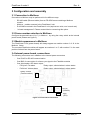
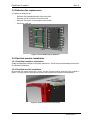
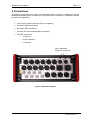
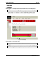
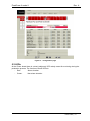
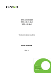
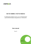
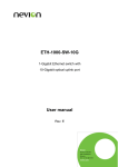
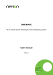
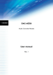
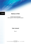
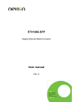
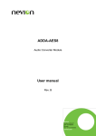
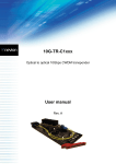
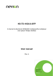
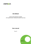
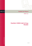
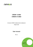
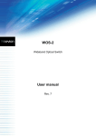
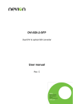
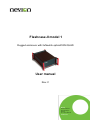
Flashcase-II model 1 Rugged enclosure with 2xNeutrik opticalCON QUAD User manual Rev. C Nevion Nordre Kullerød 1 3241 Sandefjord Norway Tel: +47 33 48 99 99 nevion.com FlashCase-II model 1 Rev. A Nevion Support Nevion Europe Nevion USA P.O. Box 1020 3204 Sandefjord, Norway Support phone 1: +47 33 48 99 97 Support phone 2: +47 90 60 99 99 1600 Emerson Avenue Oxnard, CA 93033, USA Toll free North America: (866) 515-0811 Outside North America: +1 (805) 247-8560 E-mail: [email protected] See http://www.nevion.com/support/ for service hours for customer support globally. Revision history Current revision of this document is the uppermost in the table below. Rev. Repl. Date Sign 0 - 2014-03-06 AJM Change description Initial revision, copied from FlashCase II general manual. nevion.com | 2 FlashCase-II model 1 Rev. A Contents Revision history ........................................................................................................ 2 1 Product overview ................................................................................................... 4 1.1 Key features .................................................................................................................. 4 2 Specifications ........................................................................................................ 5 2.1 Ambient temperature ..................................................................................................... 5 2.2 External power supplies ................................................................................................ 5 2.3 Internal voltage sources, max power ............................................................................. 5 2.4 GPI relays ..................................................................................................................... 5 3 Configuration and assembly .................................................................................. 6 3.1 Connection to Multicon .................................................................................................. 6 3.2 Frame number selection in Multicon .............................................................................. 6 3.3 Module appearance in Multicon ..................................................................................... 6 3.4 Internal power board, connections................................................................................. 6 3.5 Defective fan replacement ............................................................................................. 7 3.6 Flashlink module installation.......................................................................................... 7 3.6.1 Flashlink backplane installation .................................................................................. 7 3.6.2 Flashlink module installation....................................................................................... 7 3.7 The fiber fix board ......................................................................................................... 8 3.8 EMC considerations ...................................................................................................... 8 3.9 EMC gaskets ................................................................................................................. 8 4 Connections .......................................................................................................... 9 5 Operation............................................................................................................. 10 5.1 Multicon........................................................................................................................10 5.2 LEDs ............................................................................................................................11 5.3 Alarms, required actions ...............................................................................................12 5.3.1 Fan alarms ................................................................................................................12 5.3.2 Voltage alarms ..........................................................................................................12 5.3.3 Fuse alarm ................................................................................................................13 5.3.4 Temperature alarm ....................................................................................................13 Product Warranty.................................................................................................... 14 Appendix A Materials declaration and recycling information .................................. 15 A.1 Materials declaration ....................................................................................................15 A.2 Recycling information...................................................................................................15 nevion.com | 3 FlashCase-II model 1 Rev. A 1 Product overview Figure 1: Front and rear view The FlashCase is a building block in Nevion’s awardwinning Flashlink Live Media Networking solution. It is a plug-and-play stagebox for transport of video, audio, data, sync and intercom from/to video and audio ingest positions. The FlashCase’s modular design is customizable to fit each application. It supports all Flashlink modules and covers a complete range of 3G-SDI video and audio processing as well as dark fiber video, data and Ethernet transport. The FlashCase also features an in-band management solution that enables control and monitoring of equipment in remote locations. The FlashCase II model 1 features 2 Neutrik OpticalCON QUAD connectors which provide access to 4 or 8 fibers of video, audio and data transport. The models connector scheme has been carefully designed to fit a two camera ingest. The model can also be upgraded with an 8 channel CWDM filter to extend the number of signals transported. 1.1 Key features Supports up to 5 Flashlink modules Rugged connectors Rugged water resistant housing for reliable performance in harsh environment Compact and lightweight – fully populated weight is under 5 kilograms / 11 pounds Optional CWDM support Internal fans and power supply monitoring nevion.com | 4 FlashCase-II model 1 Rev. A 2 Specifications 2.1 Ambient temperature The equipment will meet the guaranteed performance specification under the following environmental conditions: Operating ambient temperature range: 0°C to +35°C Operating relative humidity range: <90% (non-condensing) The equipment will operate without damage under the following environmental conditions: Temperature range: Relative humidity range: -10°C to +40°C <95% (non-condensing Warning: Exposure to direct sunlight during operation can result in the equivalent ambient temperature exceeding the specified allowed maximum. 2.2 External power supplies The external power supplies must meet the following specifications: Voltage: Supplied power: Ripple and noise: Min. 10.0VDC Max. 18.0VDC Min. 55W continuous Max. 100mVpp The product is shipped SL-PWR-90-FlashCase which is a desktop power supply for indoor use only. For outdoor applications use power solutions suited for the current conditions. FlasehCase II supports redundant power supply schemes by using the two power inlet. PSU failure on one of the attached PSU is reported by GPI as well as by Multicon. Each power inlet is protected by a a fuse. Broken fuse is reported by GPI and Multicon. status This fuse can be changed at the internal power board. A spare fuse is mounted close to the active fuses. 2.3 Internal voltage sources, max power The unit has 10pcs card slots and is designed to contain up to 5pcs one card- or two card FL-modules and combinations of such modules. The power limitations for the internal power board are as follows: “+5V”: Max 25W “+15V”: Max 7.5W “-15V”: Max 7.5W These limits are absolute and may limit the number and combination of Flashlink modules. 2.4 GPI relays Please keep within the following limits: Voltage: Current: Max +/- 30VDC between terminals Max 1A through terminals nevion.com | 5 FlashCase-II model 1 Rev. A 3 Configuration and assembly 3.1 Connection to Multicon Connection to Multicon may be performed in four different ways: RS-422 cable (Ethernet cable) from an FR-2RU frame containing a Multicon module Multicon module mounted in the FlashCase-II unit D-422-MG mounted in the FlashCase-II unit (requires two units, one in each end) “In band management”. Please contact Nevion concerning this option. 3.2 Frame number selection in Multicon Configure the desired frame (0 to 7) in Multicon power board (Please see figure 3). by using the rotary switch at the internal 3.3 Module appearance in Multicon The FlashCase-II unit (power board) will always appear as module number 6 of 10 in the Multicon frame. The mounted Flashlink modules will appear as numbers 1 to 5, with number 5 in the card position furthest from the power board. 3.4 Internal power board, connections The following connectors are in addition to the internal power connectors One RJ-45 for RS-422 communication One BNC for connection of a frame sync signal to the Flashlink modules One 4pin header, GPI alarm output; Pin1/pin2: Fan alarm Relay output, shorted when in alarm status Pin3/pin4: Voltage alarm Relay output, shorted when in alarm status Rotary switch (Frame number) BNC (Sync) RJ-45 (RS-422) 4pin (GPI) Figure 2: Power board connections nevion.com | 6 FlashCase-II model 1 Rev. A 3.5 Defective fan replacement To replace a defective fan: Release the backplate/chassis from the profile Release the fan connector from the board Remove the fan by unscrewing the two screws Mount the new fan Fan 1 Fan 2 Figure 3: Fans numbering ref. Multicon 3.6 Flashlink module installation 3.6.1 Flashlink backplane installation Install the backplane closest to the power board first. This is the recommended procedure for an effortless installation. 3.6.2 Flashlink module installation Ensure that the plastic board clip “clicks” into the correct position and locks the module in place. This may require pushing the module with a gentle force against its backplane. Figure 4: Correct position for board clip nevion.com | 7 FlashCase-II model 1 Rev. A 3.7 The fiber fix board FlashCase-II contains a board for the organization of optical components (such as CWDM filters and splitters) and fibers. The mounting holes is designed specifically for optical components provided by Nevion. Use the board to organize excessive fiber lengths. This will minimize the risk of fiber damage. The fiber clip circles have a diameter of 5cm. Make sure no fibers have a bending diameter lower than this value. The twin holes along the long edges are for cable ties of 2-2.5mm width. Figure 5: Fiber fix board layout Figure 6: Fiber fix board mounted in chassis 3.8 EMC considerations Electrical cables should be kept away from the power board to ensure minimum noise impact from the switching supplies. 3.9 EMC gaskets Verify that all gaskets are properly mounted along the edge of the profile before mounting end plates and panels with handles. nevion.com | 8 FlashCase-II model 1 Rev. A 4 Connections All external connections are made at the backplate which contains, in addition to the two standard redundant power connectors, all input and output connections to Flashlink modules and optical components. 2x XLR 4-pin power connector (Sony compatible) 2x Neutrik OpticalCon Quad 6x female XLR connectors 6x male XLR connectors8x BNC connectors 4x RJ45 connectors o 1x Ethernet o 2x GPI and data o 1x Intercom 2pcs. redundant 4p power connectors Figure 7: Mounted backplate nevion.com | 9 FlashCase-II model 1 Rev. A 5 Operation 5.1 Multicon Figure 8 shows fan no. 2 failing and no external power supply connected to input 1. NOTE: An alarm will be triggered when the system is started with only one external power source connection. This is a prompt to verify connection source. If the intention is to connect to one source, please acknowledge the alarm If the intention is to connect to two sources, please check the connections Figure 8: front page Figure 9 shows the configuration page. NOTE: There are no user configurable parameters or alarm thresholds for this product. NOTE: Fan voltage has no alarm in , however; a fan alarm (“Fan 1 fail”, “Fan 2 fail”) will be triggered when a significant drop in fan voltage occurs. nevion.com | 10 FlashCase-II model 1 Rev. A Figure 9: configuration page 5.2 LEDs At the Power board there is a dual (red/green) LED mainly meant for monitoring during the production process. The function of these LEDs is: Red: Green: Alarm situation Non-alarm situation nevion.com | 11 FlashCase-II model 1 Rev. A 5.3 Alarms, required actions Required actions when a fan alarm is present are dependent on the incident with regard to power load and environmental temperature. 5.3.1 Fan alarms 5.3.1.1 One fan alarm Load status <= 50% (<= 20W) Ambient temperature Within spec. Expected consequences None, the operation may be completed undisturbed Within spec. <= 25°C None, the operation may be completed undisturbed >50% (> 20W) > 25°C The Flashlink modules will function for a period of uncertain duration depending on the margins with regard to ambient temperature and power load. Required actions Replace the defective fan when operation is completed Replace the defective fan when operation is completed Replace defective fan as soon as possible. NOTE: Replacement may be performed while the unit is fully functioning by releasing the chassis/backplate from the profile. Table 1 Fan alarm, action plan The above table is the suggested action plan. Actual results are dependent on factors such as: The condition of the Flashlink modules Actual bit rate Transmission margins 5.3.1.2 Two fan alarms triggered simultaneously This indicates a serious failure in the fan power circuit, and the unit should be repaired as soon as possible. The Flashlink modules will function for a period of uncertain duration depending on the margins with regard to ambient temperature and power load. 5.3.2 Voltage alarms 5.3.2.1 Internal voltages A voltage below the lower threshold may indicate an overload incident and should be investigated. A voltage above the upper limit indicates an error at the internal power board which should be repaired/replaced. 5.3.2.2 External voltages The defective power supply should be replaced. nevion.com | 12 FlashCase-II model 1 Rev. A 5.3.3 Fuse alarm A fuse failure usually indicates an overload incident. Check the status of all Flashlink modules. 5.3.4 Temperature alarm The temperature alarm is triggered when one of the measured temperatures reaches the alarm threshold. When both fans are working properly, a temperature alarm indicates an overload incident of either power consumption or ambient temperature or a combination of both. One or two failing fans can also trigger this alarm. nevion.com | 13 FlashCase-II model 1 Rev. A Product Warranty The warranty terms and conditions for the product(s) covered by this manual follow the General Sales Conditions by Nevion, which are available on the company web site: www.nevion.com nevion.com | 14 FlashCase-II model 1 Rev. A Appendix A Materials declaration and recycling information A.1 Materials declaration For product sold into China after 1st March 2007, we comply with the “Administrative Measure on the Control of Pollution by Electronic Information Products”. In the first stage of this legislation, content of six hazardous materials has to be declared. The table below shows the required information. Toxic or hazardous substances and elements 組成名稱 Part Name 鉛 汞 镉 六价铬 多溴联苯 Lead Mercury Cadmium Hexavalent Polybrominated (Pb) (Hg) (Cd) Chromium biphenyls (Cr(VI)) (PBB) 多溴二苯醚 Polybrominated diphenyl ethers (PBDE) <Product> O O O O O O <Power supply, if delivered with unit> O O O O O O O: Indicates that this toxic or hazardous substance contained in all of the homogeneous materials for this part is below the limit requirement in SJ/T11363-2006. X: Indicates that this toxic or hazardous substance contained in at least one of the homogeneous materials used for this part is above the limit requirement in SJ/T11363-2006. This is indicated by the product marking: A.2 Recycling information Nevion provides assistance to customers and recyclers through our web site http://www.nevion.com/. Please contact Nevion’s Customer Support for assistance with recycling if this site does not show the information you require. Where it is not possible to return the product to Nevion or its agents for recycling, the following general information may be of assistance: Before attempting disassembly, ensure the product is completely disconnected from power and signal connections. All major parts are marked or labeled to show their material content. Depending on the date of manufacture, this product may contain lead in solder. Some circuit boards may contain battery-backed memory devices. nevion.com | 15