1
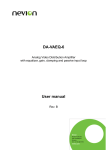
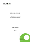
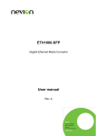
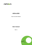
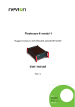
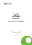
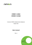
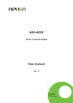
ADC-AES ADC-AES Audio Converter card User manual Rev. F Nevion Nordre Kullerød 1 3241 Sandefjord Norway Tel: +47 33 48 99 99 nevion.com ADC-AES Rev. F Nevion Support Nevion Europe Nevion USA P.O. Box 1020 3204 Sandefjord, Norway Support phone 1: +47 33 48 99 97 Support phone 2: +47 90 60 99 99 1600 Emerson Avenue Oxnard, CA 93033, USA Toll free North America: (866) 515-0811 Outside North America: +1 (805) 247-8560 E-mail: [email protected] See http://www.nevion.com/support/ for service hours for customer support globally. Revision history Current revision of this document is the uppermost in the table below. Rev. Repl. Date Sign F 5 2015-05-11 MB 5 4 3 4 3 2 2010-06-10 2007-10-23 2007-09-10 AA 2 1 B A 1 B A - 2004-02-10 2002-11-02 2002-09-04 2001-01-25 Change description Cover page update; DoC removed; no other changes to content New template. Updated Appendix A. New front page and removed old logo. Added Materials Declaration and EFUP; updated EC Declaration of Conformity. C2 backplane description Typos, formatting, specifications. Figures, corrected details for first production run. Preliminary version nevion.com | 2 ADC-AES Rev. F Contents 1 General description ................................................................................................. 4 2 Block diagram .......................................................................................................... 5 3 Technical description ............................................................................................... 6 4 Configuration ........................................................................................................... 7 4.1 Analogue input levels ...................................................................................................... 7 5 Specifications .......................................................................................................... 8 5.1 Measurement conditions.................................................................................................. 8 5.2 Analogue inputs ............................................................................................................... 8 5.3 Digital outputs.................................................................................................................. 8 5.4 Digital input...................................................................................................................... 9 6 Connector modules ............................................................................................... 10 6.1 ADC-AES-C1..................................................................................................................10 6.2 ADC-AES-C2..................................................................................................................11 6.3 Mounting of the connector module..................................................................................12 6.4 Analogue signals ............................................................................................................12 6.5 C1 digital signals ............................................................................................................13 7 Module status ........................................................................................................ 14 7.1 LED’s – Light Emitting Diodes ........................................................................................14 General environmental requirements for Nevion equipment..................................... 15 Product Warranty ...................................................................................................... 16 Appendix A Materials declaration and recycling information..................................... 17 nevion.com | 3 ADC-AES Rev. F 1 General description The ADC-AES card is a reference quality audio A/D converter. It is one of the Flashlink series of modules. It will convert four analogue audio channels with the highest possible quality and produce two AES3 stereo digital audio signals. Each converter has dual AES outputs which are available on the C1 backplane connector. Only one output per converter is available on the C2 backplane. The card may be used with, or without an external AES clock signal and may be run at nominal or double sampling rates. The ADC-AES has internal clocks for 48 kHz and 44.1 kHz based rates but can be used with any external sampling rate 29 kHz – 100 kHz. nevion.com | 4 ADC-AES Rev. F 2 Block diagram nevion.com | 5 ADC-AES Rev. F 3 Technical description The ADC-AES card was designed as a reference audio converter with a highly audio optimised signal path. Careful design of the input circuitry was needed to maintain a high dynamic range whilst minimising distortion. Jitter of the sampling clock is kept to a minimum by the use of a two-stage PLL clock recovery circuit as recommended in AES-2id. The analogue audio input circuit is a DC coupled, electronic differential amplifier with a gain of -6 dB. The use of input coupling capacitors would degrade the common mode rejection ratio of the input amplifiers. The signal is then AC coupled to an inverting variable gain stage with gains ranging from –8 dB to –17 dB. The gain variation is performed by switching extra resistors in parallel with the input resistor. The stage feeds the input of the A/D converter directly and the choice of op-amp is quite important in order to achieve a low output noise. The stage also feeds an inverting amplifier, which feeds the inverting A/D converter input. This last stage must have an output noise that is even lower than the previous one. The AES transmitter chip is configured as the interface clock master. This means that the AES output chip produces the bit clock and the word clock required for the serial interfaces between itself and the converters. The A/D converter chip uses the same master clock frequency for both nominal and double sample rates. This means that we can use the same crystal oscillators for both sampling modes. The external sync signal can be nominal or double the sample rate, independent of the sampling mode on the card, i.e. the card may sample at 96 kHz while the external sync signal is a 48 kHz signal. The sampling mode is set with the DIP switch 2-8 for both converters. Clock jitter in a reference A/D converter must be kept very low. By the time the external clock signals reach the card they often have more jitter than the internal clock oscillator. The best solution is realized when using the external AES signal to lock the internal crystal oscillator. The ADC-AES has an advanced clock management system that locks quickly to an external clock. The master clock is taken temporarily from the AES receiver but switches to the low jitter oscillator when it, in turn, has locked to the received signal. The ADC-AES has oscillators for 48 and 44.1 based sampling rates but only one will be powered up at any time. When power is applied to the card, the sample rate is decided by the DIP switch configuration. If an external AES signal is detected, the input AES circuit reports the received sample rate to the microcontroller which then switches to the appropriate oscillator if necessary or possible. The external sync signal always has priority and the sampling rate of the card will always be derived from the external sync signal, if present. Each converter has dual independent AES3 transformer isolated 110 outputs which are available on the 15 pin D-sub connector of the C1 backplane module. The optional C2 backplane connector should be used if 75 AES-3id outputs are required. The C2 backplane connector has only one output per converter due to space restrictions. The card has a microcontroller which controls the clock switching, the AES drivers and controls the LEDs on the front of the card. It also monitors the 5V and 15V power voltages and reports them to the Gyda system controller when present. nevion.com | 6 ADC-AES Rev. F 4 Configuration The ADC-AES has two eight-way miniature DIP switches located near the front of the card. Groups of 3 switches control the input gain of the analogue inputs. Switches marked 1L and 1R control the levels for converter 1 while switches marked 2L and 2R control the levels for converter 2. The settings for the level switches are presented in the following table. 4.1 Analogue input levels 0 corresponds to off. 1 corresponds to on. The three numbers in the top row should be read as: S2,S1,S0. Switches dBu @ 0 dBFS 000 +24 001 +21 010 +20 011 +18 100 +19 101 +17.2 110 +16.4 111 +15 Switch 1-8 sets the default sample rate. 0 = 48 kHz, 1 = 44.1 kHz. Switch 2-8 sets the sampling mode. 0 is nominal rate (48 or 44.1 kHz), 1 is double rate (96 or 88.2 kHz). Note: The external sync input always takes priority for the sampling rate. The figure below shows the DIP switch SW1 set for + 18 dBu @ 0 dBFS and an internal sampling rate of 48 kHz. nevion.com | 7 ADC-AES Rev. F 5 Specifications 5.1 Measurement conditions Sampling rate 48 kHz Ambient temperature 25 C Measurement bandwidth 20 Hz – 20 kHz Detector RMS Input overload level (0 dBFS) + 24 dBu 5.2 Analogue inputs Number of inputs 4 electronically balanced Common mode voltage tolerance 30 V Input impedance (differential) 25 k Frequency response 10 Hz – 21.5 kHz +0 dB , -1 dB Passband ripple 0.001 dB Group delay 65 samples Stopband attenuation 110 dB Dynamic range1 Min. 112 dB(A) (0 dBFS @ +15 dBu) Typ. 117 dB(A) Max. –95 dB THD+N @ -1 dB FS Typ. –102 dB Intermodulation distortion 2 @ - 12 dB FS Max. –85 dB Typ. –104 dB Crosstalk Max. –100 dB Typ. –110 dB CMRR (0 Hz – 8 kHz) Min. 70 dB Typ. 80 dB 5.3 Digital outputs Internal sampling rates 44.1, 48, 88.2 and 96 kHz Intrinsic jitter 200 ps peak-peak JTF corner frequency 2 Hz JTF peaking 0 dB 5.3.1 ADC-AES-C1 backplane Number of outputs 2 * 2 transformer balanced Format AES3-1992 Output impedance 110 1 2 |(THD+N of –60 dB FS signal)| + 60 SMTE 4:1 60 Hz + 7 kHz nevion.com | 8 ADC-AES Connector Rev. F D-sub 15 pin female. 5.3.2 ADC-AES-C2 backplane Number of outputs 2 unbalanced Format AES-3id Output impedance 75 Connector BNC 5.4 Digital input External sampling rates 29 kHz – 100 kHz 5.4.1 ADC-AES-C1 backplane Format AES3-1992 Input impedance 110 Connector D-sub 15 pin female. 5.4.2 ADC-AES-C2 backplane Format AES-3id Input impedance 75 Connector BNC nevion.com | 9 ADC-AES Rev. F 6 Connector modules 6.1 ADC-AES-C1 nevion.com | 10 ADC-AES Rev. F 6.2 ADC-AES-C2 nevion.com | 11 ADC-AES Rev. F 6.3 Mounting of the connector module Usually, the backplane modules will be delivered mounted in a frame which is part of the order. The details of how the connector module is mounted if delivered unmounted, can be found in the user manual for the frame FR-2RU-10-2. This manual is also available from our web site: http://www.nevion.com/ 6.4 Analogue signals nevion.com | 12 ADC-AES Rev. F 6.5 C1 digital signals nevion.com | 13 ADC-AES Rev. F 7 Module status The status of the module can be monitored in two ways. Gyda-SC (system controller). LED's at the front of the sub-rack. The LED's are mounted on the module itself, whereas the Gyda-SC is a separate module giving detailed information of the status of the card. The functions of the LED's are described in sections 7.1. The Gyda-SC is described in a separate user manual. 7.1 LED’s – Light Emitting Diodes The status of the module can be easily monitored visually by the LED's at the front of the module. The LED's are visible through the front panel as shown below. The ADC-AES has 4 LED's each showing a status. The position of the different LED's is shown above. Diode \ state Status Red LED Module is faulty: Replace Green LED Orange Module is OK Card has not been Module power is OK programmed External Sync. status Loss of sync. signal No electrical input signal. Other sample rate NA Input signal present and identical to the DIP setting 48 kHz / 96 kHz Normal mode Output Sample rate Sample mode Input signal present but different to the DIP setting 44.1 kHz / 88.2 kHz Double rate nevion.com | 14 ADC-AES Rev. F General environmental requirements for Nevion equipment 1. 2. - The equipment will meet the guaranteed performance specification under the following environmental conditions: Operating room temperature range: 0°C to 50°C Operating relative humidity range: <90% (non-condensing) The equipment will operate without damage under the following environmental conditions: Temperature range: -10°C to 55°C Relative humidity range: <95% (non-condensing) nevion.com | 15 ADC-AES Rev. F Product Warranty The warranty terms and conditions for the product(s) covered by this manual follow the General Sales Conditions by Nevion, which are available on the company web site: www.nevion.com nevion.com | 16 ADC-AES Rev. F Appendix A Materials declaration and recycling information A.1 Materials declaration For product sold into China after 1st March 2007, we comply with the “Administrative Measure on the Control of Pollution by Electronic Information Products”. In the first stage of this legislation, content of six hazardous materials has to be declared. The table below shows the required information. Toxic or hazardous substances and elements 組成名稱 Part Name ADC-AES 鉛 汞 镉 六价铬 多溴联苯 多溴二苯醚 Lead Mercury Cadmium Hexavalent Polybrominated Polybrominated (Pb) (Hg) (Cd) Chromium biphenyls diphenyl ethers (Cr(VI)) (PBB) (PBDE) O O O O O O O: Indicates that this toxic or hazardous substance contained in all of the homogeneous materials for this part is below the limit requirement in SJ/T11363-2006. X: Indicates that this toxic or hazardous substance contained in at least one of the homogeneous materials used for this part is above the limit requirement in SJ/T11363-2006. This is indicated by the product marking: A.2 Recycling information Nevion provides assistance to customers and recyclers through our web site http://www.nevion.com/. Please contact Nevion’s Customer Support for assistance with recycling if this site does not show the information you require. Where it is not possible to return the product to Nevion or its agents for recycling, the following general information may be of assistance: Before attempting disassembly, ensure the product is completely disconnected from power and signal connections. All major parts are marked or labeled to show their material content. Depending on the date of manufacture, this product may contain lead in solder. Some circuit boards may contain battery-backed memory devices. nevion.com | 17