1
Distributed by
AUSTRALIA
Brown & Watson International Pty Ltd
Knoxfield, Victoria 3180.
Telephone (03) 9730 6000
Facsimile (03) 9730 6050
National Toll Free 1800 113 443
NEW ZEALAND
Narva New Zealand Ltd
22-24 Olive Road
PO Box 12556 Penrose
Auckland, New Zealand
Telephone (09) 525 4575
Facsimile (09) 579 1192
IS018
Issue 2 21.3.12
1 x 85A Solenoid
1 x Surge Protector
1 x 4m Battery Cable (Red)
1 x 60cm Battery Cable (Black)
1 x 3m Switch cable (Blue)
1 x Rocker Switch
2 x Large Battery Lugs
4 x Small Battery Lugs
1 x Positive Battery Terminal
1 x Negative Battery Terminal
2 x Black Heat Shrink
4 x Red Heat Shrink
2 x Insulated Blade Terminals
4 x Insulated Ring Terminals
1 x Wire Tap (white)
10 x Cable Ties
2 x Solenoid Mounting Screws
WARNING
• PLEASE READ THESE INSTRUCTIONS COMPLETELY PRIOR TO INSTALLATION.
• BATTERIES PRODUCE EXPLOSIVE GASES - Ensure no sparks or flames are present.
• Wear eye protection
• Vehicles must be in “NEUTRAL ”or “PARK ”, park brakes “ON ”
• Follow all vehicle manufacturer’s instructions
• Beware of moving parts
• Battery Isolators are designed for negative ground alternator systems with batteries
of the same nominal voltage
• Batteries of differing voltages cannot be used
INSTALLATION - CONNECTION
To make the electrical connections, all cables need to be made to the correct length using
cable lugs and heatshrink. Cable lugs should be crimped or soldered to the stripped battery cable and then protected with the heatshrink.
1.
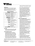
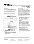
Follow the diagram below to complete the installation.
FEATURES
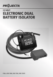
Heavy Duty Solenoid
A heavy duty, 85A solenoid made with a plated steel housing with 5/16” copper contact
terminals provides the main control. It parallels the two batteries when the ignition is
turned on and provides the essential isolation between the auxiliary and main battery
when the ignition is off.
Ignition Switch
If the auxiliary battery is significantly larger than the starting battery, the auxiliary may
flatten the starting when the ignition is turned on, not allowing the engine to start. The
ignition switch allows the isolator to be turned off from within the cabin to allow the engine
to be started before activating the solenoid.
Surge Protection
Provides surge protection for
vehicles with electronic ignition
systems.
Suits all vehicles
The solenoid isolator can be
fitted to all 12V vehicle types.
PART No.
DBS085K
VOLTAGE
12V only
CHARGING CURRENT
85A/150A peak
CHARGE TYPE
Parallel
CONTROL
Ignition
MOUNTING
Surface/firewall
CURRENT DRAW
780mA when charging
VOLTAGE DROP
None
SURGE PROTECTION
Yes (SG100)
INSTALLATION - MOUNTING
1.
2.
3.
Disconnect the negative battery cable (Earth) from the vehicle’s starting battery.
Note: To prevent the loss of vehicle electronic memories, radio presets & security
codes, it is recommended that an “Electrical System Memory Protector” be used.
Mount the auxiliary battery cradle and fit the auxiliary battery.
Use the two supplied screws to mount the Solenoid in a convenient location as
near to the main battery as possible. Keep the Solenoid as far as possible from the
exhaust manifold, turbo or any other high temperature components. Do not mount
on the engine.
To check for correct operation:
1. With the ignition switch set at 'ACC' (Accessories) or 'OFF' the LED in the rocker switch
should be off and the solenoid should be open (batteries not connected in parallel).
2. Turn the ignition switch to the 'ON' position and then switch the rocker switch to 'ON',
the LED in the switch should illuminate and the solenoid should close, connecting both
batteries in parallel (This can be checked with a continuity meter across the solenoids
main terminals or can be confirmed by listening for a 'click' as the solenoid closes.)
3. Turn the ignition switch to the 'OFF' position or switch the rocker switch to 'OFF', the
LED in the switch will turn off and the solenoid will open (batteries no longer cannected in
parallel).
Note: The Rocker switch can be used to disable the dual battery system, this is particularly useful if your Auxiliary battery is very flat, disable the dual battery system before attempting to crank the engine and then enable once the engine has started.