1
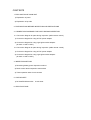
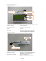
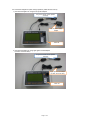
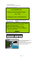
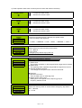
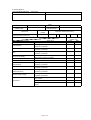
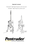
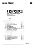
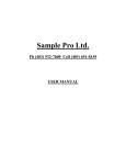
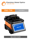
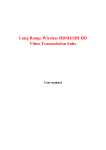
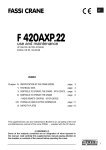
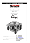
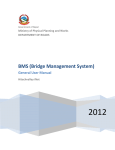
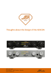
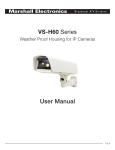
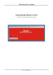
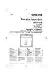
RX-2A RC-500/RCW-500 RADIO/CABLE REMOTE CONTROL TESTER USER'S MANUAL April 21, 2009 CONTENTS 1. EXPLANATION OF MAIN UNIT 1) Explanation of panel 2) Explanation of top side 2. PREPARATIONS BEFORE INSPECTION AND PRECAUTIONS 3. CONNECTION DIAGRAMS FOR PARTS DURING INSPECTION 3.1 Connection diagram for parts during inspection (radio remote control) 1) Connection diagram for using AC-DC power adapter 2) Connection diagram for using cigar lighter socket adapter (for both 12 and 24 VDC) 3.2 Connection diagram for parts during inspection (cable remote control) 1) Connection diagram for using AC-DC power adapter 2) Connection diagram for using cigar lighter socket adapter (for both 12 and 24 VDC) 4. INSPECTION METHOD 1) Remaining battery power inspection method 2) Radio control tester inspection start method 3) Tester operation state check contents 5. CHECK SHEET 1) RC-500/RCW-500 series 6. SPECIFICATIONS check sheet 1. EXPLANATION OF MAIN UNIT 1) Explanation of panel (4) LCD panel (1) Battery insertion slot (2) Receiver power switch (3) SW1 The panel surface is made up of the battery insertion slot, receiver power switch, LCD panel, and SW1. (1) Battery insertion slot .... Insert the battery holder (2) Receiver power switch .... Put the power switch when testing (3) SW1 .... Not used (4) LCD panel .... Displays the remaining amount of battery power and operation when the radio control operates operates. 2) Explanation of top side (5) 12 VDC power socket (6) Receiver connector socket The top side is made up of the 12 VDC power socket and receiver connector socket. (5) 12 VDC power socket (6) Receiver connector socket .... Plug in the AC-DC power adapter or cigar lighter socket adapter (for both 12 and 24 VDC). .... Plug in the receiver connector. (Be sure to plug in the converter connector.) Page 1 of 10 2. PREPARATIONS BEFORE INSPECTION AND PRECAUTIONS 1) Before using, connect the power supply to the power connector on the side. The power supply comes from the cigar lighter socket (12/24 VDC) of the car or truck. Or the power from household electrical outlets (100 to 240 VAC, 50/60 Hz). 2) Always unplug the power supply after use. Page 2 of 10 3. CONNECTION DIAGRAMS FOR PARTS DURING INSPECTION 3.1 Connection diagram for parts during inspection (radio remote control) 1) Connection diagram for using AC-DC power adapter Plug in the radio remote control receiver connector. AC-DC power supply adapter Main unit 2) Connection diagram for using cigar lighter socket adapter (for both 12 and 24 VDC) Plug in the radio control receiver connector. Cigar lighter socket adapter (for both 12 and 24 VDC) Main unit Page 3 of 10 3.2 Connection diagram for parts during inspection (Cable remote control) 1) Connection diagram for using AC-DC power adapter Plug in the remote control operator connector. AC-DC power supply adapter Main unit 2) Connection diagram for using cigar lighter socket adapter (for both 12 and 24 VDC) Plug in the remote control operator connector. Cigar lighter socket adapter (for both 12 and 24 VDC) Main unit Page 4 of 10 4. INSPECTION METHOD 1) Remaining battery power inspection method Radio control tester start-up screen RC-500/RCW-500 Remote Control System Tester Ver. 1.00 FURUKAWA UNIC CORPORATION 3 seconds after the start-up screen starts, the screen is switched. Remaining battery power measurement screen 「When you check the remote-control system」 Please connect the remote-control system, and push the "power" switch. 「When you check the battery power」 Please insert the battery holder in the loading slot of "BATTERY CHECKER". BATTERY POWER 0.00 V Remaining battery power result value Normal voltage Converted voltage Stop voltage 4.8 V min. 4.8 - 4.5 V 4.5 V max. Use OK OK NG Battery holder insertion method Be sure to insert the battery holder facing in the correct direction as shown in the figure in the left. The amount of remaining battery power can only be measured if the battery holder is inserted in the correct direction. Align the tester insertion slot and battery holder arrows. Page 5 of 10 2) Radio control tester measurement start method (radio control with selector switches) Remaining battery power measurement screen 「When you check the remote-control system」 Please connect the remote-control system, and push the "power" switch. 「When you check the battery power」 Please insert the battery holder in the loading slot of "BATTERY CHECKER". BATTERY POWER 0.00 V When the receiver of the radio control with selector switches is connected with the connector and the tester [POWER (RECEIVER)] switch is pressed, the screen changes as follows. STORE HOOK SWING C.C.W C.W MODE BOOM EXT RET SPEED HIGH MEDIUM LOW HOOK UP DOWN HORN MAIN CONTACT ERROR E-STOP BATTERY BOOM UP DOWN SPEED LEVER % * If the tester [POWER (RECEIVER)] switch is pressed with the receiver connector not connected, the screen changes as follows. If this screen appears, it means that the receiver connector is not connected normally. Check the connection status. STORE HOOK MODE SPEED HIGH MEDIUM LOW HOOK UP DOWN HORN MAIN CONTACT ERROR E-STOP BATTERY The radio connection of is thenot remote-control The control operating BOOM BOOM system is error. normally. SPEED LEVER EXT UP SWING C.C.W C.W RET DOWN Page 6 of 10 % 3) Tester operation state check contents (remote control with selector switches) STORE HOOK : Lit when the switch is ON. : Off when the switch is OFF. MODE : Lit when the switch is ON. : Off when the switch is OFF. HORN : Lit when the switch is ON. : Off when the switch is OFF. SPEED HIGH MEDIUM LOW MAIN CONTACT ERROR E-STOP BATTERY MAIN CONTACT ERROR E-STOP BATTERY : Each time the speed switch is pressed, the speed moves to the next step in the sequence --> HIGH --> MEDIUM --> LOW --> HIGH --> MEDIUM --> LOW --> Switch ON the key switch and the power switch. ⇒ Lit = Normal ⇒ Off = Fault * emergency stop buttun stays power off. Radio control with selector switches Transmitter (1) Switch fault: Some switch operation or other stayed ON for longer than 5 minutes. (2) Switch fault: The opposing switch operation stayed ON for longer than1 second. (3) Volume fault/disconnection: The voltage for the speed control volume is abnormal. Receiver (1) Receiver CPU error: Error of RAM check or watchdog timer (2) Setting switch setting error: Setting error of low speed mode, frequency group or frequency selection mode MAIN CONTACT ERROR E-STOP BATTERY Switch OFF the key switch or switch ON the emergency stop switch. OFF ⇒ Normal Lit ⇒ Fault Page 7 of 10 MAIN CONTACT ERROR E-STOP BATTERY Lights up when preparing to replace the battery (when the battery voltage is 4.5 to 4.8 V). OFF for any other voltage. SWING C.C.W C.W Lights up when the selector switch is set to swing counter-clockwise ( ). SWING C.C.W C.W Lights up when the selector switch is set to swing clockwise ( ). BOOM EXT RET Lights up when the selector switch is set to telescopic extend. BOOM EXT RET Lights up when the selector switch is set to telescopic retract. HOOK UP DOWN Lights up when the selector switch is set to hook up. HOOK UP DOWN Lights up when the selector switch is set to hook down. BOOM UP DOWN Lights up when the selector switch is set to derrick up. BOOM UP DOWN Lights up when the selector switch is set to derrick down. SPEED LEVER 0% 0% is normal when the transmitter lever is not operated. 100% is normal when the transmitter lever is pulled all the way. SPEED LEVER 50% SPEED LEVER If the transmitter lever is slowly pulled and the degree of opening of the lever increases without any sudden leaps, this is normal. 100% Page 8 of 10 5. CHECK SHEET 1) RC-500/RCW-500 series check sheet Company name Model Delivery date Check item Radio control transmitter remaining battery power test Inspection locations Main contact Hook retraction Mode change Horn Speed mode display Error warning Emergency stop Selector switch (derrick boom) Selector switch (winch) Selector switch (telescopic boom) Selector switch (swing) Speed lever Signature Date Machine No. Radio control manufacture No. Measurement Inspection results (Check one.) voltage V Good Check item Does it light up? Does it light up and go out when the button is pressed? Does it light up and go out when the button is pressed? Does it light up and go out when the button is pressed? Does the light-up speed change each time the button is pressed? Lit? Lit? Does it light up and go out when the button is pressed? Does it light up and go out when the button is pressed? Does it light up and go out when the button is pressed? Does it light up and go out when the button is pressed? Does the speed change from 0% to 100%? 0% when switch not operated? Is the speed value free of sudden jumps? Page 9 of 10 Replace Bad Inspection results (Check one.) Good Bad Specifications Applicable radio controls/remote controls RC-500H, RC-500HA series (made by Hetronic) RCW-500 series (remote control specifications) Power voltage: 100 - 240 VAC, 50/60 Hz, 0.3 A output + 12 V = 1 A (using power adapter) A vehicle cigar lighter socket can be used (12 V or 24 V). Battery checker built-in LCD panel display Battery voltage contents Speed lever signal Error signal Battery warning Other ON - OFF signals Dimensions 125 mm H × 200 mm W × 50 mm T Main unit weight 600 g Accessories AC-DC power supply adapter Cigar lighter socket adapter (for both 12 and 24 VDC) Receiver connection converter adapter Bag User's manual Protection decal Warranty period One year from purchase Page 10 of 10