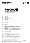
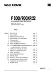
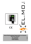
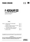
1
Operator’s Manual
Data Monitor Unit 3000
MO00009
11_2004
11_2004
00
GB
Operator’s manual
00
2
MO00009_0
Foreword
The contents in this technical manual concern the electronic overload
safety device (EOP) named DMU3000 installed on the crane.
The information of this booklet are to be considered as additional specifications to the rules already set forth in the Crane User Manual.
Reading this manual is essential to learn how the DMU3000 system
works. It also helps to operate with the crane under safe conditions,
at maximum performances.
Sol.Ge. S.p.A. All rights reserved
No part of this may be published without prior written permission.
Operator’s manual
00
3
MO00009_0
Indix
1 - WORK PRINCIPLES.........................................................................................................................4
2 - DESCRIPTION OF CONTROL PANEL FUNCTIONS
Main panel..............................................................................................................................................4
Additional panel......................................................................................................................................5
Optionals panel ......................................................................................................................................5
3 - START OF DMU3000 DEVICE
Stand-by .................................................................................................................................................7
Crane opening in safety .........................................................................................................................7
4 - WORKING WITH THE CRANE ......................................................................................................8
5 - USE OF SUPPLEMENTARY FLY-JIB AND GRAB/ROTATOR ...............................................10
6 - USE OF RADIO REMOTE CONTROL
“SCANRECO” radio remote control......................................................................................................12
“HETRONICS-QUES” radio remote control .........................................................................................13
“AUTOMATIC SLOW DOWN” ..............................................................................................................13
FPI function (optional) ..........................................................................................................................13
Enabling the pitch control disabling selector switch .............................................................................13
7 - ADDITIONAL FUNCTION/OPTIONAL
Work in front area, automatic decreasing of crane performances........................................................14
Work stops with winch use ...................................................................................................................14
Protective crane down-grading for work with grab ...............................................................................15
Control devices ....................................................................................................................................15
Notes about clogged filter .............................................................................................................15
Check of oil high temperature ......................................................................................................16
Check of minimum oil level ..........................................................................................................16
8 - OPTIONAL........................................................................................................................................17
9 - PIN CODENUMBER
How to store PIN codenumber ............................................................................................................18
How to use PIN codenumber ...............................................................................................................19
How to delete PIN codenumber ...........................................................................................................19
How to change PIN codenumber ........................................................................................................19
10 - ANOMALIES/REMEDIES
Instructions to disconnect the device in case of emergency ...............................................................22
11 - MAINTENANCE ............................................................................................................................25
Operator’s manual
00
4
MO00009_0
1 - Work principles
The DMU3000 is an electronic overload safety device enabling to work with the crane under safe conditions,
avoiding overload manoeuvres.
IT IS ESSENTIAL TO ACTIVATE THE DEVICE BY MEANS OF THE RELEVANT CONTROLS, IN ORDER
TO OPERATE WITH THE CRANE.
During job phase, the pressure inside the lifting cylinders is constantly kept under control. The operator learns,
through acoustic and visual signals, when 90% and 100% of the max. crane performance are reached.
On the control panels located next to crane manual
controls, the cylinder which activated the device is
pointed out. This helpful indication enables to use
the crane at maximum performances of all structural
components.
The radio remote control (optional) leads to a series
of functions applied on the radio transmitter.
The device engagement does not permit the operator to make those movements with the crane, which
could bring away the load from the crane base. This
particular manoeuvre would subsequently increase
the crane lifting capacities.
Note
For further information, kindly refer to user manual
The installation of winch (optional) requires an additional control panel for the load applied to rope and engagement of end stroke devices.
2 - Description of control panel functions
2.1 Main panel
1 - main switch
3
1
2
4
2 - reset push-button
3 - emergency stop push-button
4 - acoustic alarm
5 - hours-counter
6 - warning lamp to indicate “pushed emergency
stop”
5
7 - warning lamp to indicate “device turned on”
6
8 - warning lamp to indicate reaching of “90% max.
performance”
7
9 - warning lamps to indicate “lifting cylinder at max.
performances (100%)”
10 - on/off acoustic switch
9
10
8
Operator’s manual
00
5
MO00009_0
2.2 Additional panel
3
Based on the crane version, the available additional
control panel may be one of the two types shown
herebelow.
2
4
1 - main switch
2 - reset push-button
5
3 - emergency stop push-button
6
4 - acoustic alarm
8
5 - warning lamp to indicate “pushed emergency
stop”
3
1
6 - warning lamp to indicate “device turned on”
7
7 - warning lamp to indicate reaching of “90% max.
performance”
5
8 - warning lamps to indicate “lifting cylinder at max.
performances (100%)”
6
2.3 Optional panel
Other panels may be available on the crane, according to technical requirements and to accessories.
The single functions are shortly described as follows:
1
6
2
3
5
4
1 - emergency stop push-button
2 - main switch
7
5
9
8
11
13
10
12
14
9 - warning lamp to indicate crane booms positioned
in the work area in front of truck (reduced crane lifting capacity)
3 - warning lamp to indicate “pushed emergency
stop”
10 - warning lamp to indicate “clogged oil filter”
4 - warning lamp to indicate “device turned on”
11 - warning lamp to indicate “reaching of max.
hydraulic oil temperature”
5- warning lamp to indicate “activated oil cooler”
6 - warning lamps to indicate pressure status inside
the different crane lifting cylinders
7 - warning lamp to indicate reaching of “winch 90%
max. performance”
8 - warning lamp to indicate engagement of one
winch end stroke device or “reaching of winch max.
performance”
12 - warning lamp to indicate “low oil level in the
tank”
13 - warning lamp to indicate “activated device for
grab use”
14 - warning lamp to indicate “anomaly to DMU3000
device or requested crane service”.
Operator’s manual
00
6
MO00009_0
3 - Start of DMU3000 device
After inserting truck p.t.o., please carefully follow these instructions, to engage the electronic overload
device:
TURN THE KEY MAIN SWITCH
by moving the key into “I” position, the device is
electrically engaged
CHECK THAT THE “STOP” WARNING LAMP
SHALL NOT TURNED ON
if the warning lamp is on, one emergency stop pushbutton is pushed
to release it, turn the push-button clockwise
THE DEVICE IS UNDER AUTO-DIAGNOSTIC
PHASE
once control is finished, the warning lamps at side
and the acoustic alarm operate for one second, in
case of positive result
CHECK THAT THE “ON” WARNING LAMP IS
LIGHTING
if the warning lamp is lighting, the first start phase
gave a positive result. Otherwise, re-check all above
stated points
PUSH THE “RESET” PUSH-BUTTOM WHILE
FLASHING
after a few seconds of fix light, the push-button starts
to flash slowly. Then, after pushing, it switches off to
show that the start phase is over
Operator’s manual
00
7
MO00009_0
CHOICE OF ACOUSTIC ALARM
by operating the switch, the acoustic alarm may be
selected: either continuous type (it only extinguishes
at alarm end) or timer type (it extinguishes 5 seconds
after alarm start).
CAUTION
Carrying out a preliminary functionality check, raise the 1st boom cylinder upwards at full
stroke, without load. The DMU3000 device shall avoid the outlet manoeuvre of the basic crane
extensions. In case of fly-jib, open at maximum: the DMU3000 shall be activated. To unblock
the crane, read the instructions as per chapter 4.
3.1 Stand-by
If, during the job, no controlbank lever has been
operated for over 30 minutes, the DMU3000 is in
STAND-BY position and the warning lamp shown in
the picture starts to flash (two flashes alternated by
a pause). To work with the crane, begin the whole
start procedure from key switch. To start manoeuvering the crane, a whole start-up procedure shall
be launched. A distinction shall be made whether
using the crane manually (thru the controlbank) or
by radio-controls.
- use of the crane in manual mode: repeat the starting procedure by turning the key switch and pressing
the RESET button.
- use of the crane via radio control: press the emergency stop button on the radio control, then release
the button and connect the radio signal.
If the crane is supplied with optional panel, the
STAND-BY mode of the crane is shown on the visual
display unit V in the following way: the leds relative
to the maximum pressure values inside the cylinders
are the only ones illuminated.
3.2 Crane opening in safety
As described in the User Manual, the 1st manoeuvre
to be executed to open the crane from transport position regards the 2nd boom closure.
On some crane models supplied with pressure transducer fitted on the 2nd boom hydraulic cylinder, the
DMU3000 device blocks the controlbank operation
and, as a consequence, the crane operation, should
the right work sequence not be followed.
It is necessary to close the 2nd boom hydraulic cylinder, in order to restore the crane movements.
STOP
Operator’s manual
00
8
MO00009_0
4 - Working with the crane...
Even in presence of the DMU3000 system, the operator shall handle the loads by paying attention to the lifting
capacities shown in the load charts.
The following operative conditions may be faced:
90% of max. lifting capacity is reached
the yellow warning lamp is on, an acoustic slow intermittent signal is audible. The
crane may be operated.
90%
Bip---Bip---Bip-
100% of max. cylinder capacity is reached
the red warning lamp relevant to the cylinder reaching the max. capacity is on, an
acoustic quick intermittent signal is audible. The load may be only brought near
to crane base.
STOP
Bip-Bip-Bip-
CAUTION
A) it is always possible to bring the load close to crane base: the pressure inside the cylinders
goes down and all movements are automatically restored.
CAUTION
B) it is possible to lower both crane arms when the 2nd boom is positioned under horizontal and,
in some cases, even when it is over the horizontal but within an angle of 30°.
CAUTION
C) it is always possible to perform slewing manoeuvres.
Operator’s manual
00
9
MO00009_0
CAUTION
D) the intervention of the safety device DMU3000 can be affected by load oscillations and operating speeds: an improper operation can be easily reset executing a fast manoeuvre with the
lever corresponding to standard machine extension, in the direction of re-enter. The erasure of
an eventual improper operation depends on the shifts of the lever in the correct direction: no
movements of hydraulic extensions are necessary.
Note
When the crane shall handle the load at its max. performance, always work at slow speed,
preferably moving the cylinders one by one. otherwise, it may happen that the operative
advantages described at point b) shall not be profited.
Note
If 100% of the crane’s maximum capacity is reached (i.e.: end-of-stroke of 1st boom section, the noticeable swinging of load, configuration with horizontal articulation), reduce
the pressure of the cylinder of the 1st boom section to restore the operating conditions of
the crane using the lever that retracts the extensions of the base machine. This procedure
can be repeated 5 times at the most.
CAUTION
TO BE USED ONLY IN THOSE CASES WHEN LOAD LOWER SHALL HELP PREVENTING A
DANGEROUS SITUATION.
Pushing the “RESET” push-button on DMU3000 panelt, it starts to flash for 10 seconds. Within
this period of time, it is possible to carry out a short movement with one of the unadmitted
manoeuvres, except the extensions outlet.
CAUTION: this manoeuvre requires a further higher performance to crane.
Once the manoeuvre time is over, the crane automatically blocks again and the operator must
wait 30 seconds before repeating this procedure. Repeat is feasible until the max. emergency
limit is reached and anyhow for a maximum number of 5 times successively.
As an alternative, one can operate simultaneously onthe lever for the main boom down mtion
and, shaking it many times, the extensions retract lever. This manoeuver can only be performed
for a maximum number of 3 times successively.
This occurs in consequence of sudden operative stops or big load oscillations.
The red warning lamps relevant to cylinders showing dangerous situation are
on, an acoustic continuous signal is audible. The load may be only brought
near to crane base; no slewing manoeuvres are allowed.
STOP
Biiiiiiiiiiiiiiiiiiiii
the max. emergency limit is reached because of:
- sharp end stroke opening of cylinder (even without any load hanged on the hook);
- weight higher than crane capacity hanged on the hook and trial of lifting it quickly.
Operator’s manual
00
10
MO00009_0
The red warning lamps relevant to cylinders showing dangerous situation are on, an acoustic continuous signal
is audible. The crane can not be operated.
Biiiiiiiiiiiiiiiiiiiii
Pushing the “RESET” push-button, it starts to flash for 10 seconds. Within this period of time, it is possible to
carry out a short lowering movement, in order to unblock the crane. On cranes equipped with “speed automatic
slow down” system, in case the DMU3000 device operated because of an end stroke opening of the 1st boom,
it may happen that you don’t note the lowering of the arm, although the sound alarm stops. In such case, bring
back the lever of the controlbank to the central position and execute an additional manoeuvre to lower the
boom (no other manoeuvre is required).
Bip-Bip-Bip-Bip
On cranes equipped with remote control and “speed automatic slow down” system, the activation of the signal
indicating that the crane reached the 90% of its maximum lifting capacity due to an end stroke opening of the
1st boom, implies that boom lowering manoeuvres are at the minimal speed. In order to obtain the maximum
operating speed after some millimetres of cylinder hydraulic stroke, bring back the lever of the controlbank to the
central position and execute an additional manoeuvre to lower the boom (no other manoeuvre is required).
Note
In case the DMU3000 device stops crane operation because of sudden load movements,
or fast boom movements with heavy loads applied, check pressure by acting on the inlet
extension lever with quick shifts (max. 5 shifts).
5 - Use of supplementary fly-jib and grab/rotator
The following notes are helpful to fly-jib use on those
crane models, where the DMU3000 electronic device
is available.
- fly-jib work is assimilable to the one of crane 2nd
boom.
- fly-jib is hydraulically activated through connection
of four quick couplings.
- an electric connector is located close to the hydraulic quick couplings. The electric activation of the fly-jib
occurs when such connector is fitted
Note
Remove the electric by-pass from the plastic 2-poles connector when using the winch
with the fly-jib.
Operator’s manual
Note
00
11
Without any electric connection, the fly-jib may not be operated.
Electric connection:
electric connection at crane tip, to be carried out
when wanting to work with the fly-jib
Protection plug with electric by-pass function for
connection on crane. Remove the when using the
winch with the fly-jib.
The same protecting cap is used for the electric connection of the fly-jib to the winch end-stroke up device
(if it is not mounted).
MO00009_0
Operator’s manual
00
12
If the crane is supplied with optional panel, the
positioning of the additional fly-jib “ in negative - not
operating position” is indicated in the following way
on the visual display unit V: the STAND-BY mode
of the crane is shown on the visual display unit V in
the following way: the led relative to the maximum
pressure value inside the fly-jib cylinder is the only
one illuminated.
Note
MO00009_0
V
If the articulation is not used, the mobile metal connector can be fixed to an attachment
arranged on the articulation itself.
Using rotor/bucket equipment (in alternative to the articulation)
If a rotor/bucket is fitted to the end of the base crane, in alternative to the articulation, a metal electric connector
with the bucket programming is to be inserted (bucket key) so that the equipment can be operated hydraulically.
The bucket movements are performed with a slightly de-rating of the crane performance and only after having
enabled the commanding distributor for this type of use.
This is done through a pre-established sequence of movements of the lever dedicated to the bucket function
(lever that originally operates the supplementary extension). The lever is to be pushed up twice and pushed down
once within 2 seconds. This sequence is denominated “bucket PIN”. When the sequence has been completed,
you will hear an acoustic indication to confirm that the bucket is enabled.
6 - Use of radio remote control
The following notes are helpful to operator for use of
crane through radio remote control, which may be
of two different:
6.1 Radio remote type “SCANRECO”
Push button “1” of the push button control panel of
the radio controller acts as the acoustic indicator of
the DMU3000 device and, simultaneously, as the
RESET function.
1
Operator’s manual
00
13
MO00009_0
6.2 Radio remote type “HETRONIC-QUES”
On the transmitter, the push-button “3” serves like
acoustic alarm for DMU3000 device and, at the same
time, like RESET function.
6.3 “AUTOMATIC SLOW DOWN“
The function “AUTOMATIC SLOW DOWN” of booms
movements and extensions outlet is available in case
of work with the radio remote control, before activating the overload safety device.
3
Some seconds before hearing the quick alarm signal
(leading to crane movements stop), the “ AUTOMATIC SLOW DOWN” function is being operated.
The crane automatically reduces the max. speed of
the booms movements and extensions outlet.
Bip-Bip-Bip-Bip
Slewing speed automatically reduces if the load
applied is equal to or higher than 70-80% of the
max. load allowed.
The automatic movements stop shall occur with
low structural stresses and, MOST OF ALL, without
unforeseen load oscillations.
To restore crane movements at full speed, stop the load approach to crane base for a while. The pressure
inside the lifting cylinder causing alarm shall decrease under a predetermined value.
The movement speed of the boom sections is automatically lowered if the 2nd boom section exceeds a vertical angle of 70°. In some crane models you can position the supplementary articulation beyond the alignment
position with the 2nd boom section. This can only be done if the angle of the 2nd boom section is less than 30°.
The 2nd boom section of the crane can exceed the alignment position with the 1st boom section only if the pitch
control function is disabled (see 6.5). This operating mode is denominated “pitching”. Each crane model has a
specific maximum pitching angle, which once reached, prevents all lifting movements of the boom sections.
HETRONIC
6.4 FPI Function (optional)
It allows to increase the crane lifting capacities by
reducing the work speed.
4
It is voluntary engaged by the operator through the
push-button 4, and the warning lamp 5 shows this.
6.5 Enabling the pitch control disabling selector switch
5
SCANRECO
Some crane models envisage the pitching function
of the 2nd boom section with a consequent admitted
maximum angle.
Using a dedicated selector switch, arranged on a
lead-sealed box behind the safety guard, you can
disable the control function of this angle and reach
the maximum pitching position.
4
Operator’s manual
00
14
MO00009_0
7 - Additional functions/optional
The DMU3000 device offers additional safety functions, as described in the following chapters.
Operating a certain function, an acoustic warning alarm is audible. Moreover, should the optional display be
available, the warning lamp corresponding to the engaged safety function is lighting.
7.1 Work in front area, automatic decreasing of
crane performances
When working with the crane in front area, the device
automatically decreases performances to guarantee
truck stability, according to load charts.
Kindly refer to chapter 4 for additional information.
The warning lamp relevant to this function is lighting
on the optional panel.
7.2 Work stops with winch use
When using the winch, you can stop some of the
crane movements, which is pointed out by an acoustic alarm accompanied by a LED, if an optional panel
is installed.
Bip-Bip-Bip
A fast intermittent acoustic signal may trigger:
- when the maximum load admitted is detected on
the winch. This alarm stops all crane movements,
with the exception of the lowering movement of the
cable and retracting movement of the extensions of
the base machine and supplementary articulation.
- when the cable lifting limit switch trips. This alarm
stops all crane movements with the exception of the
cable lowering movement and retracting movement
of the extensions of the base machine and supplementary articulation. When the optional panel is
installed, the luminous LED flashes.
- when the cable lowering limit switch trips. This
alarm only stops the lowering movement of the cable
When the optional panel is installed, the luminous
LED flashes.
Slow intermittent acoustic signal
This signal triggers when 90% of the maximum load
admitted on the winch is detected. This alarm does
not stop any crane movement.
Bip-Bip-Bip
Operator’s manual
00
15
MO00009_0
7.3 Protective crane down-grading for work with
grab
When the device triggers, the corresponding luminous
LED lights up, if the optional panel is installed.
See chapter 5, on the triggering details.
7.4 Control device
7.4.1 Notes about clogged filter
When the crane is driven by a proportional distributor,
there is an acoustic/visual warning function to point
out when the delivery oil filter is clogged, which is
fitted on the piping that sends the oil of the pump to
the hydraulic system of the crane.
If the filter cartridge should clog, the operator will hear
sets of four rapid acoustic signals one after the other,
for two minutes and will see the corresponding LED
light up on the optional panel.
This acoustic indication is given each time the
DMU3000 is turned on and only after the levers have
been continuously operated for 30 minutes.
Bip-Bip-Bip-Bip
Bip-Bip-Bip-Bip
Bip-Bip-Bip-Bip
Operator’s manual
00
16
MO00009_0
Note
The engaged clogged filter alarm activates after 30 minutes of crane job, to avoid false
alarms deriving from the hydraulic oil at low temperature. Even the alarm reset will occur
after 30 minutes of work with the new, replaced filter.
Note
Eventual alarms for crane operativity or for device anomalies have priority on this function.
Note
Time passed with alarm switched on is stored by DMU3000, to prove an incorrect crane
use.
7.4.2 Check of oil high temperature
Biiiiiiiiiiiiiiiiiiiiiiiii
This function protects the hydraulic circuit components from high oil temperature. When temperature
exceeds 80°C, the crane movements are blocked,
an acoustic continuous signal is audible and the corresponding warning lamp is lighting.
Extensions reenter is the only admitted manoeuvre.
Push the RESET push-button if wanting to work with
the crane, without waiting for oil cooling. The crane
may be completely operated for 10 minutes. During
this period of time, 2 acoustic signals are audible
every 10 seconds to remind that available time is
passing.
Bip-Bip----Bip-Bip
7.4.3 Check of minimum oil level
This function protects the hydraulic circuit in consequence of insufficient hydraulic oil level.
When oil goes down the minimum level, the crane
movements are blocked, an acoustic continuous
signal is audible and the corresponding warning
lamp is lighting.
Extensions reenter is the only admitted manoeuvre.
Push the RESET push-button to restore the necessary oil level. Closure of hydraulic cylinders is
admitted. This kind of manoeuvre increases oil
level inside tank.
If functions 7.4.2 and 7.4.3 are present but the
optional display is not fitted, the corresponding lights
are fitted on the sensor mounted on the oil tank:
- green led ON: operating sensor
- yellow led ON: low oil level
- red led ON: oil temperature ≥ 80°C
Biiiiiiiiiiiiiiiiiiiiiiiii
Operator’s manual
00
17
MO00009_0
8 - Optional
The additional panel allows to display:
1
A - the percentage of pressure available inside
hydraulic cylinders
B - ordinary servicing schedule, and the functions engagements described at chapter 7.
A - On the panel, the signal V gives advice to the
operator during job, which percentage of pressure
is available inside the 1st boom cylinder, 2nd boom
cylinder and jib cylinder (if fitted). Thanks to this display, the operator may continuously check the load
applied to crane in terms of percentage compared
to max. performance.
V
B - Besides this, the signal V shows the eventual
need of crane servicing (kindly refer to User Manual
for details of this topic).
Simultaneously to signal V, which is displayed for
10 seconds from start, the red warning lamp 1 is
lighting intermittent:
- close to 50 work hours: it flashes for 10 seconds
after each start for 10 hours, to indicate that ordinary
servicing is required. A line with vertical leds on the
signal V is lighting for 10 seconds.
- close to 500 work hours: it flashes for 20 seconds
after each start for 20 hours, to indicate that careful
servicing is required. Two lines with vertical leds on
the signal V are lighting for 10 seconds.
- close to 1000 work hours: it flashes for 35 seconds
after each start for 40 hours, to indicate that extraordinary servicing is required. Three lines with vertical
leds on the signal V are lighting for 10 seconds.
Note
Careful and extraordinary servicing must be carried out by an EFFER authorized workshop, which will eliminate the visual signal and store the intervention on the DMU3000
device. Later on, this will help to always have an updated status of effected servicing.
Operator’s manual
PIN Codenumber
00
18
MO00009_0
9 - PIN Codenumber
The DMU3000 device offers the chance of inserting a personalized start codenumber. Thus, an
antitheft system comes in force: should the right
PIN codenumber not be digited, the crane may not
be operated.
?
At each crane start, insert the PIN codenumber, by
shifting the controlbank levers or by means of the
remote control (if installed on the crane).
The personalized codenumber shall be inserted by
installer or by user. The following instructions will
be helpful in case of PIN codenumber store, delete
and change.
9.1 How to store PIN codenumber
A
(to be carried out starting from crane completely
switched off)
C
PIN codenumber 111 can not be used.
A lever not shifted means ZERO.
Example: how to store the PIN 129 codenumber.
1- operate the main switch A (key switch)
2- operate the switch B to cut out the acoustic signal
a few times quickly. A short sound is audible and the
red led D relevant to 1st boom block is lighting
F
E
3- push the “RESET” push-button C once
D
4- to insert the codenumber operate:
once the 1st boom lever (simulating lower)
twice the 2nd boom lever (simulating lower)
nine times extensions outlet lever (simulating
outlet)
B
5- operate the 1st boom lever in upwards direction,
to confirm the inserted codenumber
6- the red led E relevant to 2nd boom block is lighting
Example: No of times
1
2
9
7- repeat codenumber input
8- the red led F relevant to fly-jib block is lighting and
a sound is audible for 3 seconds.
9- turn off the key main switch A.
From this moment, the crane may be operated
only after inserting the PIN codenumber.
1
PIN Codenumber: 129
Note
In case of error, the red led D relevant to 1st boom block is lighting and 2 short sounds
are audible. Push the “RESET” push-button C and repeat the procedure.
Operator’s manual
00
19
MO00009_0
9.2 How to use the PIN codenumber
With a PIN codenumber already stored, operate the main switch A: three red leds (D,E,F) on the control panel
will start flashing in the sequence to indicate that the PIN codenumber must be inserted.
Before shifting the controlbank levers, push the “RESET” push-button: the three red leds light up and the PIN
codenumber must be inserted in the DMU3000 device.
Operate the controlbank levers once simulating lower of 1st boom, 2nd boom and basic crane extension and
operate the 1st boom lever in upwards direction, to confirm.
The insertion of a wrong PIN codenumber is signalled
by three flashing red leds: push the “RESET” pushbutton and repeat the procedure of PIN codenumber
insertion.
A
C
9.3 How to delete PIN codenumber (to be carried out starting from crane completely switched
off)
1- operate the main switch A (key switch)
3- push the “RESET” push-button C once and
insert the current PIN codenumber (Ex.: 129). The
red light D relevant to 1st boom block is lighting. In
case of error, repeat the procedure and push again
the “RESET” push-button each time
4- push the “RESET” push-button C again: the three
leds are lighting
5- operate the controlbank levers once simulating
lower of 1st boom, 2nd boom and extensions outlet
F
E
2- operate the switch B to cut out the acoustic signal
a few times quickly. A short sound is audible
D
B
Example: No of times
1
1
1
+
1
6- operate the 1st boom lever once simulating
upwards of 1st boom: the red led E relevant to 2nd
boom is lighting
7- operate the controlbank levers once simulating
lower of 1st boom, 2nd boom and extensions outlet
8- operate the 1st boom lever simulating upwards
movement. The red led F relevant to fly-jib is lighting
and a sound is audible for 3 seconds
9- turn off the key main switch A.
From this moment, the crane has no PIN codenumber.
Example: No of times
1
1
1
9.4 How to change PIN codenumber (to be carried out starting from crane completely switched
off)
1- operate the main switch A (key switch)
1
=
NO PIN Codenumber
Operator’s manual
00
20
MO00009_0
A
2- operate the switch B to cut out the acoustic signal
a few times quickly. A short sound is audible
C
3- push the “RESET” push-button C once and insert
the current PIN codenumber (Ex.: 129). The red light
D relevant to 1st boom block is lighting. In case of
error, repeat the procedure and push again the
“RESET” push-button each time.
4- push the “RESET” push-button C again
F
E
5- operate the three above mentioned controlbank
levers for the desired number of times. The new PIN
codenumber is set up.
D
6- operate the 1st boom lever in upwards direction, to
confirm the inserted codenumber (EX.572)
B
7- the red led E relevant to 2nd boom block is lighting
Example: No of times
8- repeat codenumber input
9- the red led F relevant to fly-jib block is lighting and
a sound is audible for 3 seconds
5
7
2
10- turn off the key main switch A.
Note
In case of error, the red led D relevant to 1st boom block is lighting
and 2 short sounds are audible.
Push the “RESET” push-button
C and repeat the procedure from
point 5.
From this moment, the crane may be operated
only after inserting the new PIN codenumber
Note
Should the PIN codenumber be
“forgotten”, it is necessary to go
to an authorized workshop which
may intervene on DMU3000 software, in order to work again with
the crane. However, it is possible
to use the crane according to paragraph 10.1
1
+
Example: No of times
1
1
1
1
=
New PIN
codenumber: 572
10 - Anomalies/Remedies
In case of defect, the DMU3000 is audible the acoustic alarm continuous alarm. Some warning lamps
are displayed on the control panel, to give advice about the kind of anomaly occurred.
The following notes concern the main anomalies, causes and remedies, to finish a job and go to the nearest
EFFER authorized workshop. The note of “activated antitheft” is listed, should it be mistaken for anomaly.
Operator’s manual
Anomaly
00
21
Cause
MO00009_0
Remedy
No warning lamp is lighting and no Lack of electric power to DMU3000. Check integrity of the fuse located
acoustic alarm is working, even after
next to truck batteries space (7,5 A.)
a right start procedure.
All warning lamps (“100%”, “90%” and One or more controlbank lever(s) not Bring all levers back to central position
“RESET”) are lighting slowly.
in central position at time of DMU3000 and repeat the start procedure. The
start.
extensions reenter is being operated
in this condition, only after pushing
the RESET push-button.
All warning lamps (“100%”, “90%” and One or more controlbank lever(s)
“RESET”) are lighting quickly.
have the sensor disconnected from
DMU3000 or the connecting cable, or
the sensor itself, is damaged.
Check sensors status of all controlbank levers and all electric connections. Repeat the start procedure. If
problem still persists, get in touch
with an EFFER authorized workshop
immediately.
The “100%” warning lamp of 1st boom
is lighting quickly, while the other
warning lamps “RESET”, “90%” and
“100%” are fixed on.
Check sensors status and the related
electric connections. Once problem is
solved, the device will automatically
eliminate the alarm, without repeating the start procedure. If problem still
persists, get in touch with an EFFER
authorized workshop immediately.
The pressure sensor of 1st boom
cylinder is disconnected or the connecting cable, or the sensor itself, is
damaged.
As above, but while carrying out The pressure sensor of 1st boom cyl- Check hydraulic pressure and oil
upwards movement with 1st boom inder does not feel enough pressure supply to lifting cylinders, then repeat
(in support).
for lifting. P.T.O. not connected.
the start procedure. If problem still
persists, get in touch with an EFFER
authorized workshop immediately.
The “100%” warning lamp of 2nd boom
is lighting quickly, while the other
warning lamps “RESET”, “90%” and
“100%” are fixed on.
The pressure sensor of 2nd boom
cylinder and/or the relevant angle
sensing are disconnected or the
connecting cable, or the sensors
themselves, are damaged.
Check sensors status and the related
electric connections. Once problem is
solved, the device will automatically
eliminate the alarm, without repeating the start procedure. If problem still
persists, get in touch with an EFFER
authorized workshop immediately.
The “100%” warning lamp of fly-jib Lack of jib controls when fly-jib is fitted
is lighting quickly, while the other (refer to chapter 5).
warning lamps “RESET”, “90%” and
One or both pressure sensors on the
“100%” are fixed on.
fly-jib cylinder, or the angle sensing as
well are disconnected from the safety
device or the connecting cable, or the
sensors themselves, are damaged.
Connect the by-pass plug to basic
crane (refer to chapter 5).
Check sensors status and the related
electric connections. Once problem is
solved, the device will automatically
eliminate the alarm, without repeating the start procedure. If problem still
persists, get in touch with an EFFER
authorized workshop immediately.
All warning lamps (“100%”, “90%” and The DMU3000 device has a prob- Turn off and then turn on the device.
“RESET”) are fixed on.
lem.
If problem still persists, get in touch
with an EFFER authorized workshop
immediately. For crane folding, kindly
refer to paragraph 10.1.
Operator’s manual
00
22
MO00009_0
The “100%” warning lamps are light- The crane is blocked via antitheft Insert the right PIN codenumber to
ing in quick course.
system with a PIN codenumber.
start working with the crane (refer to
chapter 9.1).
The oil filter LED is lit on the optional Oil filter clogged
panel and the intermittent acoustic
signal is heard.
Replace filter (see chap.7)
10.1 Instructions to disconnect the device in case of emergency
According to the type of crane, one of the four under stated solenoid valves is available:
EV1
EV2
EV3
EV4
Operator’s manual
00
23
MO00009_0
EV1
A
B
C
A) Take away the seal put at end;
B) Mechanically block the spool inside the solenoid valve, by unloosing the ring nut; pay attention that the small
piston is not lost, because it is essential to work;
C) Invert the small piston indicated by the arrow. Insert it inside the cover for better convenience;
Then screw the ring nut again.
EV2
A
B
A) Take away the seal put at end;
B) Push the spool inside the solenoid valve;
C) Turn the spool clockwise until it is locked.
C
Operator’s manual
00
24
MO00009_0
EV3
EV4
After cutting out the solenoid valve, lay the load without increasing the outreach, bring the crane in transport
position according to User Manual instructions and go to an EFFER authorized workshop.
DANGER
With the crane in emergency condition, all safety devices are disconnected. Do not operate the
crane with loads hanged on, to avoid severe personal injuries or run the risk of life danger to
crane operator.
Operator’s manual
00
25
MO00009_0
11 - Maintenance
The electronic overload safety system does not require any servicing. The accurate choice of components
at design phase allows its use even under unfavourable weather conditions (temperature range : -30°C +
70°C).
The operation is guaranteed, even if voltage of truck batteries differs by 20% from rated one.
Obviously, check of batteries voltage is part of the regular truck controls.
During washing with hydro-polishing machine, avoid to turn the water outflow on several electric parts, as well
as on all truck components.
CAUTION
In case of weldings on truck, on crane or on truck body, disconnect the positive cable from truck
batteries, in order to cut out the electric power supply of the device.
Sol.Ge. S.p.A.
Via Bonazzi 12/14
40013 Castel Maggiore (BO)-Italy
+39 051 4181211 - Fax.: +39 051 701492
www.effer.it
e-mail: [email protected]