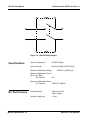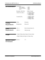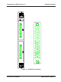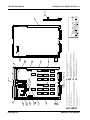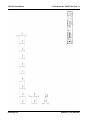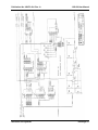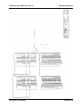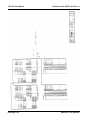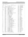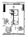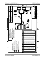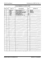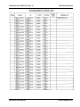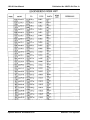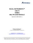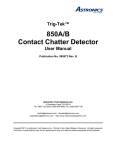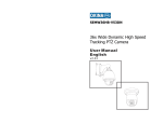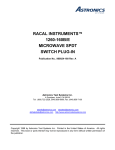
1
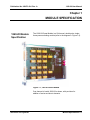
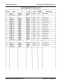
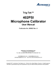
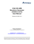
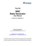
1260 VXI
SWITCHING CARD
1260-20
POWER MODULE
Publication No. 980673-004 Rev.A
Astronics Test Systems Inc.
4 Goodyear, Irvine, CA 92618
Tel: (800) 722-2528, (949) 859-8999; Fax: (949) 859-7139
[email protected] [email protected]
[email protected] http://www.astronicstestsystems.com
Copyright 2014 by Astronics Test Systems Inc. Printed in the United States of America. All rights reserved.
This book or parts thereof may not be reproduced in any form without written permission of the publisher.
THANK YOU FOR PURCHASING THIS
ASTRONICS TEST SYSTEMS PRODUCT
For this product, or any other Astronics Test Systems product that incorporates software drivers,
you may access our web site to verify and/or download the latest driver versions. The web address
for driver downloads is:
http://www.astronicstestsystems.com/support/downloads
If you have any questions about software driver downloads or our privacy policy, please contact us
at:
[email protected]
WARRANTY STATEMENT
All Astronics Test Systems products are designed to exacting standards and manufactured in full
compliance to our AS9100 Quality Management System processes.
This warranty does not apply to defects resulting from any modification(s) of any product or part
without Astronics Test Systems express written consent, or misuse of any product or part. The
warranty also does not apply to fuses, software, non-rechargeable batteries, damage from battery
leakage, or problems arising from normal wear, such as mechanical relay life, or failure to follow
instructions.
This warranty is in lieu of all other warranties, expressed or implied, including any implied warranty
of merchantability or fitness for a particular use. The remedies provided herein are buyer’s sole
and exclusive remedies.
For the specific terms of your standard warranty, contact Customer Support. Please have the
following information available to facilitate service.
1. Product serial number
2. Product model number
3. Your company and contact information
You may contact Customer Support by:
E-Mail:
[email protected]
Telephone:
+1 800 722 3262
(USA)
Fax:
+1 949 859 7139
(USA)
RETURN OF PRODUCT
Authorization is required from Astronics Test Systems before you send us your product or sub-assembly for
service or calibration. Call or contact Customer Support at 1-800-722-3262 or 1-949-859-8999 or via fax at 1949-859-7139. We can also be reached at: [email protected].
If the original packing material is unavailable, ship the product or sub-assembly in an ESD shielding bag and
use appropriate packing materials to surround and protect the product.
PROPRIETARY NOTICE
This document and the technical data herein disclosed, are proprietary to Astronics Test Systems, and shall
not, without express written permission of Astronics Test Systems, be used in whole or in part to solicit
quotations from a competitive source or used for manufacture by anyone other than Astronics Test Systems.
The information herein has been developed at private expense, and may only be used for operation and
maintenance reference purposes or for purposes of engineering evaluation and incorporation into technical
specifications and other documents which specify procurement of products from Astronics Test Systems.
TRADEMARKS AND SERVICE MARKS
All trademarks and service marks used in this document are the property of their respective owners.
•
Racal Instruments, Talon Instruments, Trig-Tek, ActivATE, Adapt-A-Switch, N-GEN, and PAWS are
trademarks of Astronics Test Systems in the United States.
DISCLAIMER
Buyer acknowledges and agrees that it is responsible for the operation of the goods purchased and should
ensure that they are used properly and in accordance with this document and any other instructions provided
by Seller. Astronics Test Systems products are not specifically designed, manufactured or intended to be
used as parts, assemblies or components in planning, construction, maintenance or operation of a nuclear
facility, or in life support or safety critical applications in which the failure of the Astronics Test Systems
product could create a situation where personal injury or death could occur. Should Buyer purchase Astronics
Test Systems product for such unintended application, Buyer shall indemnify and hold Astronics Test
Systems, its officers, employees, subsidiaries, affiliates and distributors harmless against all claims arising out
of a claim for personal injury or death associated with such unintended use.
FOR YOUR SAFETY
Before undertaking any troubleshooting, maintenance or exploratory procedure, read carefully the
WARNINGS and CAUTION notices.
This equipment contains voltage hazardous to
human life and safety, and is capable of inflicting
personal injury.
If this instrument is to be powered from the AC line (mains) through an autotransformer,
ensure the common connector is connected to the neutral (earth pole) of the power
supply.
Before operating the unit, ensure the conductor (green wire) is connected to the ground
(earth) conductor of the power outlet. Do not use a two-conductor extension cord or a
three-prong/two-prong adapter. This will defeat the protective feature of the third
conductor in the power cord.
Maintenance and calibration procedures sometimes call for operation of the unit with
power applied and protective covers removed. Read the procedures and heed warnings
to avoid “live” circuit points.
Before operating this instrument:
1. Ensure the proper fuse is in place for the power source to operate.
2. Ensure all other devices connected to or in proximity to this instrument are properly grounded or
connected to the protective third-wire earth ground.
If the instrument:
-
fails to operate satisfactorily
shows visible damage
has been stored under unfavorable conditions
has sustained stress
Do not operate until performance is checked by qualified personnel.
Publication No. 980673-004 Rev. A
1260-20 User Manual
Table of Contents
Chapter 1
MODULE SPECIFICATION .......................................................................................................... 1-1
1260-20 Module Specification ................................................................................................... 1-1
Specifications ............................................................................................................................ 1-2
DC Performance .................................................................................................................... 1-2
AC Performance .................................................................................................................... 1-3
Cooling Requirements ........................................................................................................... 1-3
Power Requirements ............................................................................................................. 1-3
Weight ................................................................................................................................... 1-3
Minimum Option 01 Firmware ................................................................................................ 1-3
Chapter 2
INSTALLATION INSTRUCTIONS ................................................................................................. 2-1
Unpacking and Inspection ......................................................................................................... 2-1
Reshipment Instructions ............................................................................................................ 2-1
Option 01 Installation ................................................................................................................. 2-2
Module Installation..................................................................................................................... 2-2
Chapter 3
MODULE SPECIFIC SYNTAX ...................................................................................................... 3-1
1260-20 Module Specific Syntax ............................................................................................... 3-1
Syntax .................................................................................................................................... 3-1
Chapter 4
DRAWINGS .................................................................................................................................. 4-1
Chapter 5
PARTS LIST ................................................................................................................................. 5-1
Chapter 6
OPTIONAL HARNESS ASSEMBLIES .......................................................................................... 6-1
Astronics Test Systems
i
1260-20 User Manual
Publication No. 980673-004 Rev. A
List of Figures
Figure 1-1, 1260-20 Power Module ............................................................................................... 1-1
Figure 1-2, 1260-20 Relay Diagram .............................................................................................. 1-2
Figure 3-1, 1260-20 Pin Connections ........................................................................................... 3-3
ii
Astronics Test Systems
Publication No. 980673-004 Rev. A
1260-20 User Manual
DOCUMENT CHANGE HISTORY
Revision
A
Astronics Test Systems
Date
Description of Change
8/14/2000
Publication
5/19/2014
Document Control release
iii
1260-20 User Manual
Publication No. 980673-004 Rev. A
This page was left intentionally blank.
iv
Astronics Test Systems
Publication No. 980673-004 Rev. A
1260-20 User Manual
Chapter 1
MODULE SPECIFICATION
1260-20 Module
Specification
The 1260-20 Power Module is a 20-channel, double-pole, singlethrow power switching module (refer to the diagram in Figure 1-2).
Figure 1-1, 1260-20 Power Module
One channel of model 1260-20 is shown, with provision for
addition of series and shunt elements.
Astronics Test Systems
Module Specification 1-1
1260-20 User Manual
Publication No. 980673-004 Rev. A
Figure 1-2, 1260-20 Relay Diagram
Specifications
Switch Configuration
20 DPST Relays
User Connector
Positronics GMCT41FOE100JC
Maximum Switchable Voltage
250VDC or 380VAC pk
Maximum Switchable Current
(DC or AC RMS)
Per Channel
8A
Maximum Switchable Power
Per Terminal
150W DC, 2000VA
DC Performance
Path Resistance
Isolation (High-Low)
Module Specification 1-2
150mΩ at 5A DC
50mΩ Typical
>109Ω
Astronics Test Systems
Publication No. 980673-004 Rev. A
AC Performance
1260-20 User Manual
Capacitance
Open Channel
Channel-Chassis
Hi-Lo
< 20pF
< 20pF
< 50pF
Bandwidth (-3dB, 50Ω )
30MHz (Typical)
Insertion Loss (50Ω )
< 0.10dB @ 100kHz
< 0.10db @ 1MHz
< 1.5dB @ 10MHz
Crosstalk (50Ω )
< -60dB @ 100kHz
< -40dB @ 1MHz
< -20dB @ 10MHz
Cooling
Requirements
Airflow
4 liters/sec
Backpressure
0.5mm H20
Power
Requirements
+5V, Ipm
0.4A (2.8A with Option 01)
+24V, Idm
10mA per relay
Weight
1.15Kg (2.56lbs) without Option 01 (Smart Card)
1.28Kg (2.84lbs) with Option 01 (Smart Card)
Minimum Option
01 Firmware
Astronics Test Systems
Revision
17.1
Module Specification 1-3
1260-20 User Manual
Publication No. 980673-004 Rev. A
This page was left intentionally blank.
Module Specification 1-4
Astronics Test Systems
Publication No. 980673-004 Rev. A
1260-20 User Manual
Chapter 2
INSTALLATION INSTRUCTIONS
Unpacking and
Inspection
1. Before unpacking the switching module, check the exterior of
the shipping carton for any signs of damage. All irregularities
should be noted on the shipping bill.
2. Remove the instrument from its carton, preserving the factory
packaging as much as possible.
3. Inspect the switching module for any defect or damage.
Immediately notify the carrier if any damage is apparent.
4. Have a qualified person check the instrument for safety before
use.
CAUTION
Proper ESD handling procedures must always be
used when packing, unpacking or installing any 1260
Series cards. Failure to do so may cause damage to
the unit.
Reshipment
Instructions
1. Contact our Customer Support department and request a
Return Material Authorization (RMA) number.
2. If possible, use the original packing material when returning
the switching module to Astronics Test Systems for
calibration or servicing. The original shipping carton, antistatic bag, and the instrument's plastic foam will provide the
necessary support for safe reshipment.
3. If the original packing material is unavailable, be sure to pack
the module in an anti-static bag and carefully pack to prevent
any shipping damage.
4. Reship in either the original or a new shipping carton.
Astronics Test Systems
Installation Instructions 2-1
1260-20 User Manual
Publication No. 980673-004 Rev. A
Option 01
Installation
Installation of the Option 01 to the 1260-20 is described in the
Installation section of the 1260 Series VXI Switching Cards
Manual.
Module
Installation
Installation of the 1260-20 Switching Module into a VXI mainframe,
including the setting of DIP switches, is described in the
Installation section of the 1260 Series VXI Switching Cards
Manual. The ID byte DIP switches, SW1-5 and SW1-6, should be
set to the OFF state.
Installation Instructions 2-2
Astronics Test Systems
Publication No. 980673-004 Rev. A
1260-20 User Manual
Chapter 3
MODULE SPECIFIC SYNTAX
1260-20 Module
Specific Syntax
The Module Specific Syntax for the 1260-20 is required in the use
of the OPEN and CLOSE commands. It will also appear in data
output by the 1260 Master in response to the PDATAOUT and
PSETUP commands.
Syntax
The Module Specific Syntax for the 1260-20 Power Switching
module is as follows:
<module address>.<switchnumber>
where <module address> is the switch card address.
<switchnumber> is the reference number of the relay to be closed,
value 0 - 19.
NOTE
The <module address> used here is NOT the VXIbus
defined logical address of the 1260 Series Master. It
is peculiar to the 1260 Series and describes the
switching module in relation to the Master. This
address corresponds to the binary value of the switch
setting of SW1 on the switching module PCB.
The 1260-20 pin connection made by each <switchnumber> are
as follows:
Astronics Test Systems
Module Specific Syntax 3-1
1260-20 User Manual
Publication No. 980673-004 Rev. A
J200
<switchnumber>
Pin Connection
0
A to D,
C to K
1
J to L,
E to H
2
M to N,
B to F
3
P to T,
S to Y
4
U to W,
X to e
5
V to a,
R to Z
6
b to j
c to d
7
m to v,
n to h
8
p to r,
f to k
9
x to s,
t to u
J201
<switchnumber>
Pin Connection
10
A to D,
C to K
11
J to L,
E to H
12
M to N,
B to F
13
P to T,
S to Y
14
W to X,
U to e
15
V to a,
R to Z
16
b to j
C to d
17
m to v,
N to h
18
p to r,
f to k
19
x to s,
t to u
Refer to Figure 3-1 for the pin configuration of connectors J200
and J201
Revised 8/14/00
Module Specific Syntax 3-2
Astronics Test Systems
Publication No. 980673-004 Rev. A
1260-20 User Manual
1260-
x
w
u
v
t
r
p
s
m
k
n
h
j
f
d
e
c
a
Z
W
T
P
L
H
b
X
R
M
J
E
D
A
Y
U
B
V
S
N
K
F
C
Figure 3-1, 1260-20 Pin Connections
Astronics Test Systems
Module Specific Syntax 3-3
1260-20 User Manual
Publication No. 980673-004 Rev. A
The Astronics Test Systems part number for the mating
connectors for 1260-20 connectors J200 and J201 is 601850, and
the contacts required for the mating connectors are Astronics Test
Systems part number 601849. 41 contacts are required to fully
populate each mating connector.
Module Specific Syntax 3-4
Astronics Test Systems
Publication No. 980673-004 Rev. A
1260-20 User Manual
Chapter 4
DRAWINGS
404773
Final Assy, 1260-20 ..................................................................... 4-3
401019
PCB Assy, 1260-20 ..................................................................... 4-4
431919
Schematic, 1260-20 ..................................................................... 4-5
Astronics Test Systems
Drawings 4-1
1260-20 User Manual
Publication No. 980673-004 Rev. A
This page was left intentionally blank.
Drawings 4-2
Astronics Test Systems
Astronics Test Systems
AFFIX LABELS AS SHOWN, ALIGN LABEL TEXT WITH APPROPRIATE
SWITCH ACTUATORS.
DISCARD UNUSED HARDWARE IN ITEM 10.
2
1.
PART OF ITEM 19 19
"VXI"
6 PLS 14
3
19
INCLUDE SHIPPING KIT, ITEM 2 IN BOX WITH ASSY.
REF
PART OF ITEM 19
"RACAL INSTRUMENTS"
3.
3
SCALE 2/1
SIDE VIEW
DETAIL A
MOUNTING BLOCK
PART OF ITEM 9 (TOP)
ITEM 8 (BOT)
TYPE PERTINENT INFORMATION ON LABEL
ITEM 24 PRIOR TO AFFIXING LABEL TO
PANEL.
SCALE 2/1
SIDE VIEW
DETAIL B
3
FLAT HEAD SCREW
PART OF ITEM 10
4
PART OF
ITEM 10
PART OF
ITEM 10
REF
REF
BEARING, PART OF
ITEMS 8 & 9
1
CHEESE HEAD SCREW AND WASHER
PART OF ITEM 10
HANDLE, PART OF ITEM 9 (TOP)
& ITEM 8 (BOT)
PLATE, PART OF ITEMS 8 & 9
LABEL, PART OF ITEM 19
RACAL INSTRUMENTS LOGO (TOP)
VXI SYMBOL (BOT)
REF
BOTTOM
4
8
24
21
SEE DETAIL "A"
9
TOP
1.00 + .125
THIS DOCUMENT AND THE TECHNICAL DATA HEREIN
DISCLOSED ARE PROPRIETARY TO RACAL INSTRUMENTS INC. AND SHALL NOT, WITHOUT THE EXPRESS WRITTEN PERMISSION OF RACAL INSTRUMENTS INC. BE USED, RELEASED OR DISCLOSED IN
WHOLE OR IN PART, OR USED TO SOLICIT QUOTATIONS FROM A COMPETITIVE SOURCE OR USED FOR
MANUFACTURE BY ANYONE OTHER THAN RACAL INSTRUMENTS INC. THE INFORMATION HEREON HAS
BEEN DEVELOPED AT PRIVATE EXPENSE, AND MAY
ONLY BE USED FOR PURPOSES OF ENGINEERING
EVALUATION AND FOR INCORPORATION INTO TECHNICAL SPECIFICATIONS AND OTHER DOCUMENTS
WHICH SPECIFY PROCUREMENT OF PRODUCTS FROM
RACAL INSTRUMENTS INC.
.70 + .125
11
16
13
15
12
5
CODE IDENT. NO.
SCALE
D 21793
SIZE
SHEET 1 OF 2
404773
DOCUMENT NO.
E
REV.
FINAL ASSY, 1260-20
TITLE
2
PART OF ITEM 2
10 PLS
3 PLS
2
PART OF ITEM 26
Instruments, Inc.
4
4 Goodyear St., Irvine, Ca 92718-2002
RACAL
TOP VIEW
1.00 + .125
BOTTOM VIEW
PROPRIETARY NOTICE
DETAIL "A"
1
PART OF ITEM 10
SEE DETAIL "B"
Publication No. 980673-004 Rev. A
1260-20 User Manual
Drawings 4-3
Drawings 4-4
42
54
SET S1 TO LOGICAL ADDRESS 1 PER TABLE 1.
REFERENCE SCHEMATIC 431919.
2.
1.
NOTES: UNLESS OTHERWISE SPECIFIED.
AREAS INDICATED TO BE FLAT AND FREE FROM SOLDER (BOTH SIDES).
INK STAMP SERIAL NO. ON COMPONENT SIDE IN INDICATED AREA.
INSTALL (ITEM 41) PCB INTO (ITEM 54) J4.
5.
4.
SET ALL S2 AND S3 SWITCHES TO (ON) OR (CLOSED) OR (1) POSITION.
DO NOT WAVE SOLDER.
6.
3.
P1 AND P2 MUST BE INSTALLED FLUSH AT RIGHT ANGLES TO BC BOARD.
2 PLCS
J200, J201
C5 AND C6 ARE NOT INSTALLED.
52
12
8.
67
66
13
4
58
2
A/R
4 PLCS A/R 61
W/J200, J201
59
4
43
48
5
6
SOLDER TAILS ON CIRCUIT SIDE OF PCB FOR P1 AND P2 (ITEM 51).
TO BE TRIMMED TO A MAXIMUM HEIGHT OF .045.
38 20 PLCS
K1 - K20
7
7
41
2 PLCS
56
S2, S3
11
13. MOUNTING HARDWARE SUPPLIED WITH J200 AND J201
TO BE INSTALLED WITH ITEMS 66 AND 67 A/R
12. SOLDER TAILS ON CIRCUIT SIDE OF PCB FOR J200, J201 (ITEM 52)
2 ROWS NEAREST EDGE OF PC BOARD TO BE TRIMMED TO A MAXIMUM
HEIGHT OF .045.
11. SOLDER TAILS ON CIRCUIT SIDE OF PCB FOR J3 & J4 (ITEM 54)
3 ROWS (9 PINS) NEAREST EDGE OF PC BOARD TO BE TRIMMED TO A
MAXIMUM HEIGHT OF .045.
10. INSTALL (ITEM 42) PCB INTO (ITEM 54) J3.
9.
SERIAL NO. 3
401919
7.
A/R
3 PLCS
32
2 PLCS 50
TP1, TP2
10
2 PLCS
J3, J4
11
40
PROPRIETARY NOTICE
THIS DOCUMENT AND THE TECHNICAL DATA HEREIN
DISCLOSED ARE PROPRIETARY TO RACAL INSTRUMENTS INC. AND SHALL NOT, WITHOUT THE EXPRESS WRITTEN PERMISSION OF RACAL INSTRUMENTS INC. BE USED, RELEASED OR DISCLOSED IN
WHOLE OR IN PART, OR USED TO SOLICIT QUOTATIONS FROM A COMPETITIVE SOURCE OR USED FOR
MANUFACTURE BY ANYONE OTHER THAN RACAL INSTRUMENTS INC. THE INFORMATION HEREON HAS
BEEN DEVELOPED AT PRIVATE EXPENSE, AND MAY
ONLY BE USED FOR PURPOSES OF ENGINEERING
EVALUATION AND FOR INCORPORATION INTO TECHNICAL SPECIFICATIONS AND OTHER DOCUMENTS
WHICH SPECIFY PROCUREMENT OF PRODUCTS FROM
RACAL INSTRUMENTS INC.
SCALE
D
SIZE
21793
CODE IDENT. NO.
SHEET 1 OF 5
401019
DOCUMENT NO.
G
REV.
PCB ASSY, 1260-20 OPT.
POWER SWITCH
TITLE
4 Goodyear St., Irvine, Ca 92718-2002
RACAL Instruments, Inc.
4
53
REF
3 PLCS
1260-20 User Manual
Publication No. 980673-004 Rev. A
Astronics Test Systems
Publication No. 980673-004 Rev. A
Astronics Test Systems
1260-20 User Manual
Drawings 4-5
1260-20 User Manual
Drawings 4-6
Publication No. 980673-004 Rev. A
Astronics Test Systems
Publication No. 980673-004 Rev. A
Astronics Test Systems
1260-20 User Manual
Drawings 4-7
1260-20 User Manual
Drawings 4-8
Publication No. 980673-004 Rev. A
Astronics Test Systems
Publication No. 980673-004 Rev. A
Astronics Test Systems
1260-20 User Manual
Drawings 4-9
1260-20 User Manual
Drawings 4-10
Publication No. 980673-004 Rev. A
Astronics Test Systems
Publication No. 980673-004 Rev. A
Astronics Test Systems
1260-20 User Manual
Drawings 4-11
1260-20 User Manual
Drawings 4-12
Publication No. 980673-004 Rev. A
Astronics Test Systems
Publication No. 980673-004 Rev. A
Astronics Test Systems
1260-20 User Manual
Drawings 4-13
1260-20 User Manual
Drawings 4-14
Publication No. 980673-004 Rev. A
Astronics Test Systems
Publication No. 980673-004 Rev. A
1260-20 User Manual
Chapter 5
PARTS LIST
404773
Final Assembly, 1260-20 ...................................................................... 5-3
404935
Shipping Kit, 1260-20 ........................................................................... 5-3
401919
PCB Assy, 1260-20 .............................................................................. 5-4
List of Suppliers ............................................................................................ 5-6
Astronics Test Systems
Parts List 5-1
1260-20 User Manual
Publication No. 980673-004 Rev. A
This page was left intentionally blank.
Parts List 5-2
Astronics Test Systems
Publication No. 980673-004 Rev. A
Astronics Test Systems
1260-20 User Manual
Parts List 5-3
1260-20 User Manual
Parts List 5-4
Publication No. 980673-004 Rev. A
Astronics Test Systems
Publication No. 980673-004 Rev. A
Astronics Test Systems
1260-20 User Manual
Parts List 5-5
1260-20 User Manual
Publication No. 980673-004 Rev. A
ASTRONICS TEST SYSTEMS INC.
IRVINE, CA
Parts List 5-6
Astronics Test Systems
Publication No. 980673-004 Rev. A
1260-20 User Manual
Chapter 6
OPTIONAL HARNESS ASSEMBLIES
The following harness assemblies are used to connect the 1260-20 to Freedom Series Test
Receiver Interfaces.
Each harness documentation consists of an assembly drawing, parts list, system wire list and wire
list.
407276
Virginia Panel, Inc. Series VP90 Interface Harness
407277-005
TTI Testron, Inc. Interface Harness
407277-008
TTI Testron, Inc. Interface Harness
For more information on Astronics Test Systems complete line of Test Receivers Interface solution,
contact your Sales Representative.
Astronics Test Systems
Product Support 6-1
1260-20 User Manual
Publication No. 980673-004 Rev. A
This page was left intentionally blank.
Optional Harness Assemblies 6-2
Astronics Test Systems
Astronics Test Systems
4
1.5 ± 0.3
3
PIN 1
5
3 WHITE INK STAMP J--- ATTHE SIDE OF
CONNECTORS. LOCATE APPROXIMATELY
WHERE SHOWN.
2. 2 CABLE ASSEMBLIES TO BE FORMED:
- J200 TO J100.
- J201 TO J101.
1. SEE WIRE LISTFOR CONNECTIONS AND
CONTACT ASSIGMENT.
NOTES:
J100 & J101
3
2 PLCS
J100,J101
2
1
54.0 ± 1.0
2 PLCS
J200,J201
41 REQD
8
7. ENCLOSE CABLES IN SINGLE BAG AND
IDENTIFY WITH PARTNUMBER AND
CURRENTREVISION.
7
DWG. NO.
6. MATING ITA CONNECTOR FOR J100 &
J101 IS VIRGINIA PANEL P/N
510 108 101. USE ITA PIN P/N
610 110 129.
5 SPRAY PROTECTIVE COATING (ITEM 6)
AFTER MARKING.
4 MARK J--- ON APPROPRIATE
SIZE SHRINK TUBING AND LOCATE
APPROXIMATELY WHERE SHOWN.
3
2
41 REQD
2 PLCS
J100,J101
A/R
407276
4
3
4
ZONE
1
5
9
PIN A
5
4 Goodyear St.,Irvine,CA.92718-2002
PIN A
4.0 ± 0.5
J200
SCALE
SIZE
1:1
980340 REV. F
CAGE CODE
CALC.WT
DWG NO.
ACT.WT
1
SHEET
1
407276
OF
9
HARNESS ASSY, 1260-20, VP90
TITLE
4
1.5 ± 0.3
JR 5/8/96
SL 5-7-96
REVISED PER EO NO.
JR 4/23/96
SL 4-16-96
23773
APPROVED
LMC
24324
3-16-95
1546
REVISED PER EO NO.
DATE
1
REVISED PER EO NO.
REVISIONS
C
DESCRIPTION
RELEASED PER DRN NO.
C
REV.
A
B
REV
SH
J201
A
B
C
D
THIS DOCUMENT AND THE TECHNICAL DATA HEREON DISCLOSED ARE PROPRIETARY
TO RACAL INSTRUMENTS INC. AND SHALL NOT, WITHOUT THE EXPRESS WRITTEN
PERMISSION OF RACAL INSTRUMENTS INC. BE USED, RELEASED OR DISCLOSED
IN WHOLE OR IN PART, OR USED TO SOLICITQUOTATION FROM A COMPETITIVE
SOURCE OR USED FOR MANUFACTURE BY ANYONE OTHER THAN RACAL INSTRUMENTS
INC. THE INFORMATION HEREON HAS BEEN DEVELOPED ATPRIVATE EXPENSE,
AND MAY ONLY BE USED FOR PURPOSES OF ENGINEERING EVALUATION AND FOR
INCORPORATION INTO TECHNICAL SPECIFICATIONS AND OTHER DOCUMENTS WHICH
SPECIFY PROCUREMENT OF PRODUCTS FROM RACAL INSTRUMENTS INC.
PROPRIETARY NOTICE
J101
4
C
REV.
A
B
C
D
Publication No. 980673-004 Rev. A
1260-20 User Manual
Product Support 6-3
1260-20 User Manual
Optional Harness Assemblies 6-4
Publication No. 980673-004 Rev. A
Astronics Test Systems
Publication No. 980673-004 Rev. A
1260-20 User Manual
Astronics Test Systems
Product Support 6-5
1260-20 User Manual
Optional Harness Assemblies 6-6
Publication No. 980673-004 Rev. A
Astronics Test Systems
Publication No. 980673-004 Rev. A
1260-20 User Manual
Astronics Test Systems
Product Support 6-7
1260-20 User Manual
Optional Harness Assemblies 6-8
Publication No. 980673-004 Rev. A
Astronics Test Systems
Publication No. 980673-004 Rev. A
1260-20 User Manual
Astronics Test Systems
Product Support 6-9
1260-20 User Manual
Optional Harness Assemblies 6-10
Publication No. 980673-004 Rev. A
Astronics Test Systems
Publication No. 980673-004 Rev. A
1260-20 User Manual
Astronics Test Systems
Product Support 6-11
1260-20 User Manual
Optional Harness Assemblies 6-12
Publication No. 980673-004 Rev. A
Astronics Test Systems
Publication No. 980673-004 Rev. A
1260-20 User Manual
Astronics Test Systems
Product Support 6-13
1260-20 User Manual
Optional Harness Assemblies 6-14
Publication No. 980673-004 Rev. A
Astronics Test Systems
Publication No. 980673-004 Rev. A
1260-20 User Manual
Astronics Test Systems
Product Support 6-15
1260-20 User Manual
Optional Harness Assemblies 6-16
Publication No. 980673-004 Rev. A
Astronics Test Systems
Publication No. 980673-004 Rev. A
1260-20 User Manual
Astronics Test Systems
Product Support 6-17
1260-20 User Manual
Optional Harness Assemblies 6-18
Publication No. 980673-004 Rev. A
Astronics Test Systems
Publication No. 980673-004 Rev. A
1260-20 User Manual
Astronics Test Systems
Product Support 6-19
1260-20 User Manual
Optional Harness Assemblies 6-20
Publication No. 980673-004 Rev. A
Astronics Test Systems
Publication No. 980673-004 Rev. A
1260-20 User Manual
Astronics Test Systems
Product Support 6-21
1260-20 User Manual
Optional Harness Assemblies 6-22
Publication No. 980673-004 Rev. A
Astronics Test Systems
Publication No. 980673-004 Rev. A
1260-20 User Manual
Astronics Test Systems
Product Support 6-23
1260-20 User Manual
Optional Harness Assemblies 6-24
Publication No. 980673-004 Rev. A
Astronics Test Systems
Astronics Test Systems
A
B
C
D
J201-A CH10 IN HI
J201-C CH10 IN LO
J201-D CH10 OUTHI
J201-K CH10 OUT LO
J201-E CH11 IN HI
J201-J CH11 IN LO
J201-H CH11 OUTHI
J201-L CH11 OUT LO
J201-B CH12 IN HI
J201-M CH12 IN LO
J201-F CH12 OUTHI
J201-N CH12 OUTLO
J201-P CH13 IN HI
J200-R CH05 IN LO
J200-a CH05 OUT HI
J200-Z CH05 OUTLO
J200-b CH06 IN HI
J200-c CH06 IN LO
J200-j CH06 OUT HI
J200-d CH06 OUT LO
J200-m CH07 IN HI
J200-n CH07 IN LO
J200-v CH07 OUT HI
J200-h CH07 OUT LO
J200-p CH08 IN HI
J200-f CH08 IN LO
J200-r CH08 OUTHI
J200-k CH08 OUT LO
J200-x CH09 IN HI
J200-t CH09 IN LO
J200-s CH09 OUTHI
J200-u CH09 OUT LO
J200-C CH00 IN LO
J200-D CH00 OUTHI
J200-K CH00 OUT LO
J200-E CH01 IN HI
J200-J CH01 IN LO
J200-H CH01 OUTHI
J200-L CH01 OUT LO
J200-B CH02 IN HI
J200-M CH02 IN LO
J200-F CH02 OUTHI
J200-N CH02 OUTLO
J200-P CH03 IN HI
J200-S CH03 IN LO
J200-T CH03 OUTHI
J200-Y CH03 OUTLO
J200-U CH04 IN HI
J200-X CH04 IN LO
J200-W CH04 OUTHI
J200-e CH04 OUTLO
J201-e CH14 OUTHI
J201-X CH14 IN LO
J201-Y CH13 OUTLO
J201-U CH14 IN HI
J201-T CH13 OUTHI
J201-S CH13 IN LO
J200-w CHAS GROUND
J200-V CH05 IN HI
J200-A CH00 IN HI
FROM SIG.
NAME
3
J201-w CHAS GROUND
J201-u CH19 OUT LO
J201-s CH19 OUTHI
J201-t CH19 IN LO
J201-k CH18 OUT LO
J201-x CH19 IN HI
J201-r CH18 OUTHI
J201-f CH18 IN LO
J201-p CH18 IN HI
J201-h CH17 OUT LO
J201-v CH17 OUT HI
J201-n CH17 IN LO
J201-m CH17 IN HI
J201-d CH16 OUT LO
J201-j CH16 OUT HI
J201-c CH16 IN LO
J201-b CH16 IN HI
J201-Z CH15 OUTLO
J201-a CH15 OUT HI
J201-R CH15 IN LO
J201-V CH15 IN HI
J201-W CH14 OUTLO
FROM SIG.
NAME
6 MARK 407277-008 ON APPROPRIATE SIZE
SHRINK TUBING APPROXIMATELY WHERE
SHOWN. PLACE APPROPRIATE SIZE
CLEAR SHRINK TUBING OVER MARKING.
FROM SIG.
NAME
4
3
5. CONNECTORS J100-J181 WILL LATER INSTALL IN RECEIVER BLOCK, TTI P/N
VGRCB-32CP. MATING ITA CONNECTOR
BLOCK IS TTI P/N VGFCB-32CP. MATING
ITA PIN IS RII P/N 602228.
FROM SIG.
NAME
4 SPRAY PROTECTIVE COATING (ITEM 7)
AFTER MARKING.
3 MARK SIGNAL NAME ON APPROPRIATE SIZE
SHRINK TUBING APPROXIMATELY WHERE
SHOWN. SEE TABULATION.
2 WHITE INK STAMP J--- APPROXIMATELY
WHERE SHOWN.
NOTES:
1. SEE WIRE LIST FOR CONTACT
ASSIGNMENTS AND CONNECTIONS.
THIS DOCUMENT AND THE TECHNICAL DATA HEREON DISCLOSED ARE PROPRIETARY
TO RACAL INSTRUMENTS INC. AND SHALL NOT, WITHOUT THE EXPRESS WRITTEN
PERMISSION OF RACAL INSTRUMENTS INC. BE USED, RELEASED OR DISCLOSED
IN WHOLE OR IN PART, OR USED TO SOLICITQUOTATION FROM A COMPETITIVE
SOURCE OR USED FOR MANUFACTURE BY ANYONE OTHER THAN RACAL INSTRUMENTS
INC. THE INFORMATION HEREON HAS BEEN DEVELOPED ATPRIVATE EXPENSE,
AND MAY ONLY BE USED FOR PURPOSES OF ENGINEERING EVALUATION AND FOR
INCORPORATION INTO TECHNICAL SPECIFICATIONS AND OTHER DOCUMENTS WHICH
SPECIFY PROCUREMENT OF PRODUCTS FROM RACAL INSTRUMENTS INC.
PROPRIETARY NOTICE
1
2
6
407277-008
82 PLCS
J100-181
8.0± 1.0
DWG. NO.
REV
1
82 PLCS
3 4
ZONE
SH
DESCRIPTION
2 4
2 PLCS
3
2
4
J201
J200
DATE
1
6.0± .5
2 PLCS
J200-201
4 Goodyear St.,Irvine,CA.92718-2002
6
41 REQD
REVISIONS
APPROVED
SCALE
SIZE
NONE
980340 REV. F
CAGE CODE
CALC.WT
ACT.WT
1
SHEET
1
10
OF
407277-008
DWG NO.
A
REV.
HARNESS ASSY,1260-20,TTI
TITLE
40.0± 1.0
A/R
J200J201
2 PLCS
REVISED PER EO NO.
REVISED PER EO NO.
REVISED PER EO NO.
RELEASED PER DRN NO.
A
REV.
PIN A
PIN A
4
A
B
C
D
Publication No. 980673-004 Rev. A
1260-20 User Manual
Product Support 6-25
1260-20 User Manual
Optional Harness Assemblies 6-26
Publication No. 980673-004 Rev. A
Astronics Test Systems
Publication No. 980673-004 Rev. A
1260-20 User Manual
Astronics Test Systems
Product Support 6-27
1260-20 User Manual
Optional Harness Assemblies 6-28
Publication No. 980673-004 Rev. A
Astronics Test Systems
Publication No. 980673-004 Rev. A
1260-20 User Manual
Astronics Test Systems
Product Support 6-29
1260-20 User Manual
Optional Harness Assemblies 6-30
Publication No. 980673-004 Rev. A
Astronics Test Systems
Publication No. 980673-004 Rev. A
1260-20 User Manual
Astronics Test Systems
Product Support 6-31
1260-20 User Manual
Optional Harness Assemblies 6-32
Publication No. 980673-004 Rev. A
Astronics Test Systems
Publication No. 980673-004 Rev. A
1260-20 User Manual
Astronics Test Systems
Product Support 6-33
1260-20 User Manual
Optional Harness Assemblies 6-34
Publication No. 980673-004 Rev. A
Astronics Test Systems