1
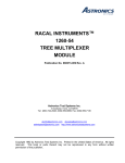
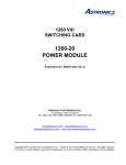
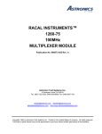
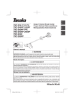
RACAL INSTRUMENTS™
1260-30
SIGNAL / MULTIPLEXER
PUBLICATION NO. 980673-005 Rev. A
Astronics Test Systems Inc.
4 Goodyear, Irvine, CA 92618
Tel: (800) 722-2528, (949) 859-8999; Fax: (949) 859-7139
[email protected] [email protected]
[email protected] http://www.astronicstestsystems.com
Copyright 1992 by Astronics Test Systems Inc. Printed in the United States of America. All rights reserved.
This book or parts thereof may not be reproduced in any form without written permission of the publisher.
THANK YOU FOR PURCHASING THIS
ASTRONICS TEST SYSTEMS PRODUCT
For this product, or any other Astronics Test Systems product that incorporates software drivers,
you may access our web site to verify and/or download the latest driver versions. The web address
for driver downloads is:
http://www.astronicstestsystems.com/support/downloads
If you have any questions about software driver downloads or our privacy policy, please contact us
at:
[email protected]
WARRANTY STATEMENT
All Astronics Test Systems products are designed to exacting standards and manufactured in full
compliance to our AS9100 Quality Management System processes.
This warranty does not apply to defects resulting from any modification(s) of any product or part
without Astronics Test Systems express written consent, or misuse of any product or part. The
warranty also does not apply to fuses, software, non-rechargeable batteries, damage from battery
leakage, or problems arising from normal wear, such as mechanical relay life, or failure to follow
instructions.
This warranty is in lieu of all other warranties, expressed or implied, including any implied warranty
of merchantability or fitness for a particular use. The remedies provided herein are buyer’s sole
and exclusive remedies.
For the specific terms of your standard warranty, contact Customer Support. Please have the
following information available to facilitate service.
1. Product serial number
2. Product model number
3. Your company and contact information
You may contact Customer Support by:
E-Mail:
[email protected]
Telephone:
+1 800 722 3262
(USA)
Fax:
+1 949 859 7139
(USA)
RETURN OF PRODUCT
Authorization is required from Astronics Test Systems before you send us your product or sub-assembly for
service or calibration. Call or contact Customer Support at 1-800-722-3262 or 1-949-859-8999 or via fax at 1949-859-7139. We can also be reached at: [email protected].
If the original packing material is unavailable, ship the product or sub-assembly in an ESD shielding bag and
use appropriate packing materials to surround and protect the product.
PROPRIETARY NOTICE
This document and the technical data herein disclosed, are proprietary to Astronics Test Systems, and shall
not, without express written permission of Astronics Test Systems, be used in whole or in part to solicit
quotations from a competitive source or used for manufacture by anyone other than Astronics Test Systems.
The information herein has been developed at private expense, and may only be used for operation and
maintenance reference purposes or for purposes of engineering evaluation and incorporation into technical
specifications and other documents which specify procurement of products from Astronics Test Systems.
TRADEMARKS AND SERVICE MARKS
All trademarks and service marks used in this document are the property of their respective owners.
•
Racal Instruments, Talon Instruments, Trig-Tek, ActivATE, Adapt-A-Switch, N-GEN, and PAWS are
trademarks of Astronics Test Systems in the United States.
DISCLAIMER
Buyer acknowledges and agrees that it is responsible for the operation of the goods purchased and
should ensure that they are used properly and in accordance with this document and any other
instructions provided by Seller. Astronics Test Systems products are not specifically designed,
manufactured or intended to be used as parts, assemblies or components in planning, construction,
maintenance or operation of a nuclear facility, or in life support or safety critical applications in
which the failure of the Astronics Test Systems product could create a situation where personal
injury or death could occur. Should Buyer purchase Astronics Test Systems product for such
unintended application, Buyer shall indemnify and hold Astronics Test Systems, its officers,
employees, subsidiaries, affiliates and distributors harmless against all claims arising out of a claim
for personal injury or death associated with such unintended use.
FOR YOUR SAFETY
Before undertaking any troubleshooting, maintenance or exploratory procedure, read carefully the
WARNINGS and CAUTION notices.
This equipment contains voltage hazardous to human life and
safety, and is capable of inflicting personal injury.
If this instrument is to be powered from the AC line (mains) through an
autotransformer, ensure the common connector is connected to the neutral (earth
pole) of the power supply.
Before operating the unit, ensure the conductor (green wire) is connected to the
ground (earth) conductor of the power outlet. Do not use a two-conductor extension
cord or a three-prong/two-prong adapter. This will defeat the protective feature of the
third conductor in the power cord.
Maintenance and calibration procedures sometimes call for operation of the unit with
power applied and protective covers removed. Read the procedures and heed
warnings to avoid “live” circuit points.
Before operating this instrument:
1. Ensure the proper fuse is in place for the power source to operate.
2. Ensure all other devices connected to or in proximity to this instrument are properly grounded or
connected to the protective third-wire earth ground.
If the instrument:
-
fails to operate satisfactorily
shows visible damage
has been stored under unfavorable conditions
has sustained stress
Do not operate until, performance is checked by qualified personnel.
DOCUMENT CHANGE HISTORY
Revision
A
Date
Description of Change
11/6/2006
Publication
7/14/2012
Initial Release
1260-30 User Manual
Publication No. 980673-005 Rev. A
NOTE FOR SYSTEMS WITH 1260-OPT 01T
The “Module-Specific Syntax” section of this manual shows the command syntax for the 1260-01S
Smart Card. If you are using the newer 1260-01T Smart Card, the commands will NOT work as
shown.
Consult the 1260-01T Manual for a description of the commands which may be used with the 126001T Smart Card.
The channel numbers described in this manual are valid for the 1260-01T. The channel numbers
continue to be used for the 1260-01T.
The syntax of the commands which use channel numbers has changed for those cards controlled
by the 1260-01T.
The new syntax used to close a channel is:
CLOSE (@ <module address> ( <channel> ) )
For example, with for a relay module whose <module address> is set to 7, closing <channel> 0 is
performed with the command:
CLOSE (@ 7 (0))
Using the older 1260-01S, the command would be (as shown in this manual):
CLOSE 7.0
Many other command syntax differences exist. Please consult chapter 2 of the 1260-01T manual
for a description of the commands which are available for the 1260-01T.
Astronics Test Systems
Addendum Page 6/98
1
Publication No. 980673-005 Rev. A
1260-30 User Manual
Control Information for the 1260-30A
The following information describes the control-register-to-relay-channel mapping for a 1260-30A
Relay Module. This information may be used to control a 1260-30A when using a 1260-01T in the
register-based mode of operation.
Each relay on this module is controlled by setting or clearing a single bit within a Control Register.
Control Registers on the module operate 8 channels simultaneously. There are eight control bits
per Control Register. Setting the bit to a 1 closes the relay; setting the bit to a 0 opens the relay.
The table below shows the mapping from logical channels to control bits. The logical channels are
used when operating the relay module in message-based mode. The control bits within the Control
Registers are used to operate the module in register-based mode.
Each Control Register is located 2 addresses from the previous Control Register. That is, each
Control Register is located at an odd address. This is shown in Table 2-2 of the 1260-01T manual.
Control Register 0 is located at the “Base A24 Address” for the module. Consult the “RegisterBased Operation” Section of Chapter 2 of the 1260-01T manual for a description of calculating
control register addresses:
Channel
0
1
2
3
4
5
6
7
8
9
10
11
12
13
14
15
16
17
18
19
20
21
22
23
24
25
26
27
28
29
30
31
32
33
34
35
36
37
38
39
2 Addendum Page 6/98
Control Register
0
0
0
0
0
0
0
0
1
1
1
1
1
1
1
1
2
2
2
2
2
2
2
2
3
3
3
3
3
3
3
3
4
4
4
4
4
4
4
4
Control Bit
0
1
2
3
4
5
6
7
0
1
2
3
4
5
6
7
0
1
2
3
4
5
6
7
0
1
2
3
4
5
6
7
0
1
2
3
4
5
6
7
Astronics Test Systems
1260-30 User Manual
Publication No. 980673-005 Rev. A
Control Information for the 1260-30B
The following information describes the control-register-to-relay-channel mapping for a 1260-30B
Relay Module. This information may be used to control a 1260-30B when using a 1260-01T in the
register-based mode of operation.
Each relay on this module is controlled by setting or clearing a single bit within a Control Register.
Control Registers on the module operate 8 channels simultaneously. There are eight control bits
per Control Register. Setting the bit to a 1 closes the relay; setting the bit to a 0 opens the relay.
The table below shows the mapping from logical channels to control bits. The logical channels are
used when operating the relay module in message-based mode. The control bits within the Control
Registers are used to operate the module in register-based mode.
Each Control Register is located 2 addresses from the previous Control Register. That is, each
Control Register is located at an odd address. This is shown in Table 2-2 of the 1260-01T manual.
Control Register 0 is located at the “Base A24 Address” for the module. Consult the “RegisterBased Operation” Section of Chapter 2 of the 1260-01T manual for a description of calculating
control register addresses:
Channel
0
1
2
3
4
5
6
7
8
9
10
11
12
13
14
15
16
17
18
19
100
101
102
103
104
105
106
107
108
109
110
111
112
113
114
115
116
117
118
119
Astronics Test Systems
Control Register
0
0
0
0
0
0
0
0
1
1
1
1
1
1
1
1
2
2
2
2
2
2
2
2
3
3
3
3
3
3
3
3
4
4
4
4
4
4
4
4
Control Bit
0
1
2
3
4
5
6
7
0
1
2
3
4
5
6
7
0
1
2
3
4
5
6
7
0
1
2
3
4
5
6
7
0
1
2
3
4
5
6
7
Addendum Page 6/98
3
Publication No. 980673-005 Rev. A
1260-30 User Manual
Control Information for the 1260-30C
The following information describes the control-register-to-relay-channel mapping for a 1260-30C
Relay Module. This information may be used to control a 1260-30C when using a 1260-01T in the
register-based mode of operation.
Each relay on this module is controlled by setting or clearing a single bit within a Control Register.
Control Registers on the module operate 8 channels simultaneously. There are eight control bits
per Control Register. Setting the bit to a 1 closes the relay; setting the bit to a 0 opens the relay.
The table below shows the mapping from logical channels to control bits. The logical channels are
used when operating the relay module in message-based mode. The control bits within the Control
Registers are used to operate the module in register-based mode.
Each Control Register is located 2 addresses from the previous Control Register. That is, each
Control Register is located at an odd address. This is shown in Table 2-2 of the 1260-01T manual.
Control Register 0 is located at the “Base A24 Address” for the module. Consult the “RegisterBased Operation” Section of Chapter 2 of the 1260-01T manual for a description of calculating
control register addresses:
Channel
0
1
2
3
4
5
6
7
8
9
100
101
102
103
104
105
106
107
108
109
200
201
202
203
204
205
206
207
208
209
300
301
302
303
304
305
306
307
308
309
4 Addendum Page 6/98
Control Register
0
0
0
0
0
0
0
0
1
1
1
1
1
1
1
1
2
2
2
2
2
2
2
2
3
3
3
3
3
3
3
3
4
4
4
4
4
4
4
4
Control Bit
0
1
2
3
4
5
6
7
0
1
2
3
4
5
6
7
0
1
2
3
4
5
6
7
0
1
2
3
4
5
6
7
0
1
2
3
4
5
6
7
Astronics Test Systems
1260-30 User Manual
Publication No. 980673-005 Rev. A
Control Information for the 1260-30D
The following information describes the control-register-to-relay-channel mapping for a 1260-30D
Relay Module. This information may be used to control a 1260-30D when using a 1260-01T in the
register-based mode of operation.
Each relay on this module is controlled by setting or clearing a single bit within a Control Register.
Control Registers on the module operate 8 channels simultaneously. There are eight control bits
per Control Register. Setting the bit to a 1 closes the relay; setting the bit to a 0 opens the relay.
The table below shows the mapping from logical channels to control bits. The logical channels are
used when operating the relay module in message-based mode. The control bits within the Control
Registers are used to operate the module in register-based mode.
Each Control Register is located 2 addresses from the previous Control Register. That is, each
Control Register is located at an odd address. This is shown in Table 2-2 of the 1260-01T manual.
Control Register 0 is located at the “Base A24 Address” for the module. Consult the “RegisterBased Operation” Section of Chapter 2 of the 1260-01T manual for a description of calculating
control register addresses:
Channel
0
1
2
3
4
100
101
102
103
104
200
201
202
203
204
300
301
302
303
304
400
401
402
403
404
500
501
502
503
504
600
601
602
603
604
700
701
702
703
704
Astronics Test Systems
Control Register
0
0
0
0
0
0
0
0
1
1
1
1
1
1
1
1
2
2
2
2
2
2
2
2
3
3
3
3
3
3
3
3
4
4
4
4
4
4
4
4
Control Bit
0
1
2
3
4
5
6
7
0
1
2
3
4
5
6
7
0
1
2
3
4
5
6
7
0
1
2
3
4
5
6
7
0
1
2
3
4
5
6
7
Addendum Page 6/98
5
Publication No. 980673-005 Rev. A
1260-30 User Manual
This page was left intentionally blank.
6 Addendum Page 6/98
Astronics Test Systems
1260-30 User Manual
Publication No. 980673-005 Rev. A
Table of Contents
Chapter 1 ............................................................................................................................ 1-1
MODULE SPECIFICATION .......................................................................................................... 1-1
1260-30 Module Specification ................................................................................................... 1-1
Specifications......................................................................................................................... 1-2
DC Performance ................................................................................................................ 1-2
AC Performance ................................................................................................................. 1-2
General .............................................................................................................................. 1-3
Minimum Option 01 Firmware............................................................................................. 1-3
Ordering Information ................................................................................................................. 1-3
Safety ........................................................................................................................................ 1-3
Chapter 2 ............................................................................................................................ 2-1
INSTALLATION INSTRUCTIONS ................................................................................................. 2-1
Unpacking and Inspection ......................................................................................................... 2-1
Reshipment Instructions ............................................................................................................ 2-1
Option 01 Installation ................................................................................................................. 2-2
Module Installation..................................................................................................................... 2-2
Configuration Settings............................................................................................................ 2-2
1260-30A............................................................................................................................ 2-3
1260-30B............................................................................................................................ 2-3
1260-30C ........................................................................................................................... 2-4
1260-30D ........................................................................................................................... 2-5
1260-30 ID Byte ..................................................................................................................... 2-5
Astronics Test Systems
i
Publication No. 980673-005 Rev. A
1260-30 User Manual
Chapter 3 ............................................................................................................................ 3-1
MODULE SPECIFIC SYNTAX ...................................................................................................... 3-1
1260-30 Module Specific Syntax ............................................................................................... 3-1
Syntax ................................................................................................................................... 3-1
CLOSE Command ................................................................................................................. 3-2
PSETUP Command ............................................................................................................... 3-2
PDATAOUT Command.......................................................................................................... 3-3
Chapter 4 ............................................................................................................................ 4-1
OPTIONAL HARNESS ASSEMBLIES .......................................................................................... 4-1
ii
Astronics Test Systems
1260-30 User Manual
Publication No. 980673-005 Rev. A
List of Figures
Figure 1-1, 1260-30 Signal/Multiplexer Scanner Module ............................................................... 1-1
Figure 1-2, 1260-30 Relay Matrix .................................................................................................. 1-2
Figure 3-1, 1260-30 J200 and J201 Connector Pin Configuration ................................................. 3-5
Figure 3-2, 1260-30 Configurations and Command Codes ........................................................... 3-6
Astronics Test Systems
iii
Publication No. 980673-005 Rev. A
1260-30 User Manual
This page was left intentionally blank.
iv
Astronics Test Systems
1260-30 User Manual
Publication No. 980673-005 Rev. A
Chapter 1
MODULE SPECIFICATION
1260-30 Module
Specification
The 1260-30 Signal/Multiplexer Scanner Module is a 1 X 40
multiplexer. It switches two lines per channel, and has the
capability of being configured as two 1 X 20 matrices, four 1 X 10
matrices or eight 1 X 5 matrices (refer to the diagram in Figure 12).
Figure 1-1, 1260-30 Signal/Multiplexer Scanner Module
Astronics Test Systems
Module Specification 1-1
Publication No. 980673-005 Rev. A
1260-30 User Manual
Com1
J1
Com2
J2
Com3
Com1
J3
Com4
J4
Com5
J5
Com6
J6
Com7
J7
Com8
Figure 1-2, 1260-30 Relay Matrix
Specifications
Maximum Switchable Voltage
220VDC, 250VAC RMS
(Terminal-Terminal or Terminal-Chassis)
Maximum Switchable Current
2A DC or RMS
Maximum Switchable Power
Per Channel
60W DC, 62.5VA AC
DC Performance
Isolation
>109Ω
AC Performance
Capacitance
Open Channel
Channel-Chassis
Hi-Lo
< 40pF
< 60pF
< 280pF
Bandwidth (-3dB, 50Ω)
10MHz (Typical)
Insertion Loss (50Ω)
< 0.1dB @ 100kHz
< 0.1db @ 1MHz
< 1.3dB @ 10MHz
Crosstalk (50Ω)
< -55dB @ 100kHz
< -45dB @ 1MHz
< -30dB @ 10MHz
Module Specification 1-2
Astronics Test Systems
1260-30 User Manual
General
Publication No. 980673-005 Rev. A
Cooling
Airflow Backpressure
4.0 liters/sec, 0.5mm H20
Power Requirements
+5V, Ipm
+24V, Idm
0.4A (2.8A with Option 01 installed)
10mA per energized relay
User Connector
SMPL 4 FOTO LB
Weight
2.59lbs (1.17Kg)
2.87lbs (1.29Kg) with Option 01
Minimum Option 01
Firmware
Revision
17.1
Ordering
Information
Model Number
Description
Part Number
1260-30A
2-wire, One, 1x40 Multiplexer
404767-001
1260-30B
2-wire, Two, 1x20 Multiplexer
404767-002
1260-30C
2-wire, Four, 1x10 Multiplexer
404767-003
1260-30D
2-wire, Eight, 1x5 Multiplexer
404767-004
Safety
Astronics Test Systems
Refer to the “FOR YOUR SAFETY” page preceding the Table of
Contents. Following all NOTES, CAUTIONS, and WARNINGS to
ensure personal safety and prevent damage to the instrument.
Module Specification 1-3
Publication No. 980673-005 Rev. A
1260-30 User Manual
This page was left intentionally blank.
Module Specification 1-4
Astronics Test Systems
1260-30 User Manual
Publication No. 980673-005 Rev. A
Chapter 2
INSTALLATION INSTRUCTIONS
Unpacking and
Inspection
1. Remove the 1260-30 module and inspect it for damage. If any
damage is apparent, inform the carrier immediately. Retain
shipping carton and packing material for the carrier’s
inspection.
2. Verify that the pieces in the package you received contain the
correct 1260-30 module option and the 1260-30 User Manual.
Notify Customer Support if the module appears damaged in
any way. Do not attempt to install a damaged module into a
VXI chassis.
3. The 1260-30 module is shipped in an anti-static bag to prevent
electrostatic damage to the module. Do not remove the
module from the anti-static bag unless it is in a static-controlled
area.
CAUTION:
Proper ESD handling procedures must always be used
when packing, unpacking or installing any 1260 Series
cards. Failure to do so may cause damage to the unit.
Reshipment
Instructions
1. Contact Customer Support for a Return Material Authorization
(RMA) number.
2. Use the original packing when returning the switching module
to Astronics Test Systems for calibration or servicing. The
original shipping carton and the instrument's plastic foam will
provide the necessary support for safe reshipment.
3. If the original packing material is unavailable, wrap the
switching module in an ESD Shielding bag and use plastic
spray foam to surround and protect the instrument.
4. Reship in either the original or a new shipping carton.
Astronics Test Systems
Installation Instructions 2-1
Publication No. 980673-005 Rev. A
1260-30 User Manual
Option 01
Installation
Installation of the Option 01 into the 1260-30 is described in the
Installation section of the 1260 Series VXI Switching Cards
Manual.
Module
Installation
Installation of the 1260-30 Switching Module into a VXI mainframe,
including the setting of DIP switches, is described in the
Installation section of the 1260 Series VXI Switching Cards
Manual. Configuration of the PCBA and setting DIP switches
SW1-5 and SW1-6 are described in the following sections.
Configuration
Settings
The 1260-30 is configurable as 1x40, two 1x20, four 1x10, or eight
1x5 multiplexers. The configuration is set by the installation of 24
gage jumpers to the board as follows:
Model
Configuration
Jumpers
1260-30A
One 1X40
All
1260-30B
Two 1X20
J1, J2, J3, J5, J6. and J7
1260-30C
Four 1X10
J1, J3, J5, and J7
1260-30D
Eight 1X5
None
Note this illustrates the principle of the 1260-30 configuration
setting. The connections to be made on the PCB are given on the
following pages.
Installation Instructions 2-2
Astronics Test Systems
1260-30 User Manual
1260-30A
Publication No. 980673-005 Rev. A
The following connections are required to configure the 1260-30
as a 1260-30A. To configure the 1260-30A from any other 126030 configuration, remove all connections not on this list, and install
22 gauge solid jumpers, listed below, unless otherwise specified.
COM 01 to E01
COM 02 to E02
COM 11 to E11
COM 12 to E12
COM 21 to E21
COM 22 to E22
COM 31 to E31
COM 32 to E32
COM 41 to E41
COM 42 to E42
COM 51 to E51
COM 52 to E52
COM 61 to E61
COM 62 to E62
COM 71 to E71
COM 72 to E72
W1-1 to W1-2
E01-1 to E12-1
E01-2 to E12-2
E23-2 to E34-1
E45-1 to E56-1
E45-2 to E56-2
*E67 1 to E00-1 Teflon stranded, 24 gauge, white
E67-2 to E00-2 Teflon stranded, 24 gauge, black
*Twisted Pair
1260-30B
The following connections are required to configure the 1260-30
as a 1260-30B. To configure the 1260-30B from any other 126030 configuration, remove all connections not on this list and install
22 gauge solid jumpers, listed, below unless otherwise specified.
COM 01 to E01
COM 02 to E02
COM 11 to E11
COM 12 to E12
COM 21 to E21
COM 22 to E22
COM 31 to E31
COM 32 to E32
COM 4l to E41
COM 42 to E42
COM 51 to E51
COM 52 to E52
COM 61 to E61
COM 62 to E62
COM 71 to E72
COM 72 to E72
W1-1 to W1-2
E01-1 to E12-1
E01-2 to E12-2
E45-1 to E56-1
E45-2 to E56-2
*E67-1 to E10-1 Teflon stranded, 24 gauge, white
Astronics Test Systems
Installation Instructions 2-3
Publication No. 980673-005 Rev. A
1260-30 User Manual
E67-2 to E10-2 Teflon stranded, 24 gauge, black
*E23-1 to E00-1 Teflon stranded, 24 gauge, white
E23-2 to E00-2 Teflon stranded, 24 gauge, black
*Twisted Pair
1260-30C
The following connections are required to configure the 1260-30
as a 1260-30C. To configure the 1260-30C from any other 126030 configuration, remove all connections not on this list and install
22 gauge solid jumpers, listed below, unless otherwise specified.
COM 01 to E10
COM 02 to E02
COM 11 to E11
COM 12 to E12
COM 21 to E21
COM 22 to E22
COM 31 to E31
COM 32 to E32
COM 41 to E41
COM 42 to E42
COM 51 to E5l
COM 52 to E52
COM 61 to E61
COM 62 to E62
COM 71 to E71
COM 72 to E72
W1-1 to Wl-2
*E01-1 to EOO-1 Teflon stranded, 24 gauge, white
E01-2 to EOO-2 Teflon stranded, 24 gauge, black
*E23-1 to E1O-1 Teflon stranded, 24 gauge, white
E23-2 to ElO-2 Teflon stranded, 24 gauge, black
*E45-1 to E20-1 Teflon stranded, 24 gauge, white
E45-2 to E20-2 Teflon stranded, 24 gauge, black
*E67-1 to E30-1 Teflon stranded, 24 gauge, white
E67-2 to E30-2 Teflon stranded, 24 gauge, black
*Twisted Pair
Installation Instructions 2-4
Astronics Test Systems
1260-30 User Manual
1260-30D
Publication No. 980673-005 Rev. A
The following connections are required to configure the 1260-30
as a 1260-30D. To configure the 1260-30B from any other 126030 configuration, remove all connections not on this list and install
22 gauge solid jumpers, listed below, unless otherwise specified.
*COM 01 to E00-1
COM 02 to E00-2
Teflon stranded, 24 gauge, white
Teflon stranded, 24 gauge, black
*COM 11 to E10-1
COM 12 to E10-2
Teflon stranded, 24 gauge, white
Teflon stranded, 24 gauge, black
*COM 21 to E20-1
COM 22 to E20-2
Teflon stranded, 24 gauge, white
Teflon stranded, 24 gauge, black
*COM 31 to E30-1
COM 32 to E30-2
Teflon stranded, 24 gauge, white
Teflon stranded, 24 gauge, black
*COM 41 to E40-1
COM 42 to E40-2
Teflon stranded, 24 gauge, white
Teflon stranded, 24 gauge, black
*COM 51 to E50-1
COM 52 to E50-2
Teflon stranded, 24 gauge, white
Teflon stranded, 24 gauge, black
*COM 61 to E60-1
COM 62 to E60-2
Teflon stranded, 24 gauge, white
Teflon stranded, 24 gauge, black
*COM 71 to E70-1
COM 72 to E70-2
Teflon stranded, 24 gauge, white
Teflon stranded, 24 gauge, black
W1-1 to W1-2
*Twisted Pair
1260-30 ID Byte
Each configuration of the 1260-30 will respond to different sets of
values for <group number> and <channel>. The set of values is
controlled by switches 5 and 6 on DIP switch S1 on the PCB. The
switch settings that correspond to the four configurations are as
follows:
Model
Astronics Test Systems
Configuration
S1 Switches
5
6
1260-30A
One 1X40
Off
Off
1260-30B
Two 1X20
On
Off
1260-30C
Four 1X10
Off
On
1260-30D
Eight 1X5
On
On
Installation Instructions 2-5
Publication No. 980673-005 Rev. A
1260-30 User Manual
This page was left intentionally blank.
Installation Instructions 2-6
Astronics Test Systems
1260-30 User Manual
Publication No. 980673-005 Rev. A
Chapter 3
MODULE SPECIFIC SYNTAX
1260-30 Module
Specific Syntax
The Module Specific Syntax for the 1260-30 is required in the use
of the OPEN and CLOSE commands. It will also appear in data
output by the Master in response to the PDATAOUT and PSETUP
commands.
Syntax
The Module Specific Syntax for the
Multiplexer/Scanner module is as follows:
1260-30
Signal
OPEN <module address>.<group number><channel>
where <module address> is the address.
<group number> is the number of switching
groups implemented in the
module. The range of values
for <group number> is up to 0-7
<channel>
is the path in the group to be
switched. For 1260-30
configurations containing more than
one group, the values for <channel>
are repeated for each group.
NOTE:
The <module address> used here is NOT the VXIbus
defined logical address of the 1260 Master. It is peculiar
to the 1260 Series and describes the switching module in
relation to the Master. This address corresponds to the
binary value of the switch setting of SW1 on the
switching module PCB.
Astronics Test Systems
Module Specific Syntax 3-1
Publication No. 980673-005 Rev. A
1260-30 User Manual
The valid values of <group number> and <channel> for the
different 1260-30 configurations are as follows:
Configuration
<channel>
<group numbers>
One 1X40
00-39
0
Two 1X20
00-19
0,1
Four 1X10
00-09
0,1,2, and 3
Eight 1X5
00-04
0,1,2,3,4,5,6, and 7
Refer to Figure 3-1 for connector pin configurations, and to Figure
3-2 for the command codes required to open and close the various
<channels> for the four configurations.
CLOSE Command
The Module Specific Syntax for the CLOSE command is the same
as for the OPEN command.
Example: OPEN 3.002
This open command will open channel 2 in Group 0 on the 126030 module at switch card address 3.
PSETUP
Command
The PSETUP command causes the specified module setup to be
transmitted to the VXI Controller. The syntax used is:
PSETUP <module address>[;<module address>] [;<module
address>] where <module address> is the switch card address.
The responses to the PSETUP command for the 1260-30A Signal
Multiplexer/Scanner is as follows:
<module address>.1260-30A 40-channel Signal Multiplexer/Scanner
Module
<module address>.BBM
<module address>.END
Module Specific Syntax 3-2
Astronics Test Systems
1260-30 User Manual
Publication No. 980673-005 Rev. A
1260-30B:
<module address>.1260-30B 20-channel Signal Multiplexer/Scanner
Module
<module address>.BBM
<module address>.END
1260-30C:
<module address>.1260-30C 10-channel Signal Multiplexer/Scanner
Module
<module address>.BBM
<module address>.END
I260-30D:
<module address>.1260-30D 5-channel Signal Multiplexer/Scanner
Module
<module address>.BBM
<module address>.END
The response to the PSETUP command consists of a header on
the first line. The header describes the model number followed by
an A or B designating four or two-wire, respectively. The next line
designates the setup mode for scanning which, by default, is
Break-Before-Make (BBM). The last line containing the 'END1'
characters denotes no more information to report.
PDATAOUT
Command
The PDATAOUT command causes the specified module to
transmit the CLOSED state of the relays within the switching
module to the 1260 Controller. The syntax used is:
PDATAOUT <module address>[.<module address>] [;<module
address>]
The responses to the PDATAOUT command is as follows:
1260-30A:
<module address>.1260-30A 40-channel Signal Multiplexer/Scanner
Module
<module address>.<channel>[,<channel>] [,<channel>]
<module address>.END
Astronics Test Systems
Module Specific Syntax 3-3
Publication No. 980673-005 Rev. A
1260-30 User Manual
1260-30B:
<module address>.1260-30B 20-channel Signal Multiplexer/Scanner
Module
<module address>.<channel>[,<channel>] [,<channel>]
<module address>.END
1260-30C:
<module address>.1260-30C 10-channel Signal Multiplexer/Scanner
Module
<module address>.<channel>[,<channel>] [,<channel>]
<module address>.END
1260-30D:
<module address>.1260-30D 5-channel Signal Multiplexer/Scanner
Module
<module ad dress>.<channel>[,<channel [,<channel>]
<module address>.END
The response to the PDATAOUT command consists of a header
on the first line as with the PSETUP response. The next line
details the channels currently closed on the module and is blank
when no channels are closed. Again, the last line is denoted by
the "END" string of characters.
Module Specific Syntax 3-4
Astronics Test Systems
1260-30 User Manual
Publication No. 980673-005 Rev. A
1260-30
A
J200
C
B
D
E
H
M
S
W
a
e
k
r
K
P
U
Y
c
h
t
DD
BB
FF
R
T
V
X
b
f
m
s
w
x
L
N
n
v
z
F
J
AA
EE
Z
d
l
p
u
y
CC
HH
J201
Figure 3-1, 1260-30 J200 and J201 Connector Pin Configuration
Astronics Test Systems
Module Specific Syntax 3-5
K2
K3
K4
K5
K6
K7
K8
k K9
J201-T
J201-m
J201-EE
J200-a
J200-v
&
&
&
J201-V
J201-p
J201-HH &
& J201-S
J201-K
&
J200-y
J200-Y
J200-t
J201-P
J201-h
J201-BB &
J200-z
J200-u
001
002
003
004
005
006
007
008
009
010
011
012
K10
K11
K12
K13
K14
K15
K16
K17
K18
K19
K20
K21
K22
K23
K24
K25
K26
K27
K28
K29
K30
K31
K32
K33
K34
K35
K36
K37
K38
K39
K40
J201-DD
J200-x
J200-s
J201-N
J201
-f
J201-AA
J200-W
J200-r
J201-M
J201-e
J201-z
J200-T
J200-m
J200-EE
J201-b
J201-w
J200-S
J200-k
J201-v
J200-N
J200-f
J200-AA
J201-x
J201-s
J200-M
J200-e
J200-z
J201-W
J201-r
&
&
&
&
&
&
&
&
&
&
&
&
&
&
&
&
&
&
&
&
&
&
&
&
&
J201-j
J200-U
J200-n
J201-K
J201-c
J201-x
J200-V
J200-p
J200-HH &
&
J201-R
J201-CC &
J
& 200-DD
J201-a
&
J201-d
J201-y
J200-P
J200-h
J200-BB
J201-Y
J201-t
J200-R
J200-j
J200-CC
J201-z
J201-u
J200-K
J200-c
J200-x
J201-U
J201-n
013
014
015
016
017
018
019
020
021
022
023
024
025
026
027
028
029
030
031
032
033
034
035
036
037
038
039
&
K1
J200-b
J200-w
&
&
J200-d
000
1260-30A
Module Specific Syntax 3-6
039
038
037
036
035
034
033
032
031
030
029
028
027
026
025
024
023
022
021
020
019
018
017
016
015
014
013
012
011
010
009
008
007
006
005
004
003
002
&
&
&
&
&
&
&
&
&
&
&
&
&
&
&
&
&
J201-n
J201-U
J200-x
J200-c
J200-K
J201-u
J201-z
J200-CC
J200-j
J200-R
J201-t
J201-Y
J200-BB
J200-h
J200-P
J201-y
J201-d
J200-v
J200-a
J201-EE
J201-m
J201-T
J200-k
J200-S
J201-w
J201-b
J200-EE
J200-m
J200-T
J201-z
J201-e
J201-M
J200-r
J200-W
J201-AA
J201
-f
J201-N
J200-s
J200-x
J201-DD
J201-K
&
&
&
&
&
&
&
&
&
&
&
&
J201-r
J201-W
J200-z
J200-e
J200-M
J201-s
J201-x
J200-AA
J200-f
J200-N
J201-v
J201-a
J
& 200-DD
&
&
&
&
J200-HH &
J200-p
J200-V
J201-x
J201-c
J201-K
J200-n
J200-U
J201-CC &
J201-j
J201-R
J200-u
J200-z
J200-b
J200-w
& J201-S
&
J201-BB &
J201-h
J201-P
J200-t
J200-Y
J201-HH &
J201-p
J201-V
J200-y
J200-d
J200-B, J200-FF, J201-B, J201-FF are chassis ground.
J201-A
& J201-C
OUT 7
J201-F
& J201-D
OUT 6
J201-E
& J201-H
OUT 5
J201-L
& J201-J
OUT 4
J200-A
& J200-C
OUT 3
J200-F
& J200-D
OUT 2
J200-E
& J200-H
OUT 1
J200-L
& J200-J
OUT 0
001
000
1260-30B
K40
K39
K38
K37
K36
K35
K34
K33
K32
K31
K30
K29
K28
K27
K26
K25
K24
K23
K22
K21
K20
K19
K18
K17
K16
K15
K14
K13
K12
K11
K10
k K9
K8
K7
K6
K5
K4
K3
K2
K1
J201-A
& J201-C
OUT 7
J201-F
& J201-D
OUT 6
J201-E
& J201-H
OUT 5
J201-L
& J201-J
OUT 4
J200-A
& J200-C
OUT 3
J200-F
& J200-D
OUT 2
J200-E
& J200-H
OUT 1
J200-L
& J200-J
OUT 0
Publication No. 980673-005 Rev. A
1260-30 User Manual
Figure 3-2, 1260-30 Configurations and Command Codes
Astronics Test Systems
K2
K3
K4
K5
K6
K7
K8
k K9
J201-T
J201-m
J201-EE
J200-a
J200-v
&
&
&
J201-V
J201-p
J201-HH &
& J201-S
J201-K
&
J200-y
J200-Y
J200-t
J201-P
J201-h
J201-BB &
J200-z
J200-u
001
002
003
004
005
006
007
008
009
Astronics Test Systems
010
011
012
K36
K37
K38
K39
K40
J200-M
J200-e
J200-z
J201-W
J201-r
&
&
&
&
&
J200-K
J200-c
J200-x
J201-U
J201-n
036
037
038
039
K31
J200-N
&
J200-R
030
035
K30
J201-v
&
J201-t
029
K35
K29
J201-a
&
J201-Y
028
J201-s
K28
J
& 200-DD
J200-BB
027
&
K27
J200-k
&
J200-h
026
J201-u
K26
J200-S
&
J200-P
025
034
K25
J201-w
&
J201-y
024
K34
K24
J201-b
&
J201-d
023
J201-x
K23
J200-EE
J200-HH &
022
&
K22
J200-p
021
J201-z
K21
J200-T
J200-m
&
&
J200-V
020
033
K20
J201-z
&
J201-x
019
K33
K19
J201-e
&
J201-c
018
J200-AA
K18
J201-M
&
J201-K
017
&
K17
J200-r
&
J200-n
016
J200-CC
K16
J200-W
&
J200-U
015
032
K15
J201-AA
J201-CC &
014
K32
K14
J201
-f
&
J201-j
013
J200-f
K13
J201-N
&
J201-R
&
K12
J200-s
&
J200-j
K11
J200-x
&
031
K10
J201-DD
&
K1
J200-b
J200-w
&
&
J200-d
000
1260-30C
039
038
037
036
035
034
033
032
031
030
029
028
027
026
025
024
023
022
021
020
019
018
017
016
015
014
013
012
011
010
009
008
007
006
005
004
003
002
&
&
&
&
&
&
&
&
&
&
&
&
&
&
&
&
&
J201-n
J201-U
J200-x
J200-c
J200-K
J201-u
J201-z
J200-CC
J200-j
J200-R
J201-t
J201-Y
J200-BB
J200-h
J200-P
J201-y
J201-d
J200-v
J200-a
J201-EE
J201-m
J201-T
J200-k
J200-S
J201-w
J201-b
J200-EE
J200-m
J200-T
J201-z
J201-e
J201-M
J200-r
J200-W
J201-AA
J201
-f
J201-N
J200-s
J200-x
J201-DD
J201-K
&
&
&
&
&
&
&
&
&
&
&
&
J201-r
J201-W
J200-z
J200-e
J200-M
J201-s
J201-x
J200-AA
J200-f
J200-N
J201-v
J201-a
J
& 200-DD
&
&
&
&
J200-HH &
J200-p
J200-V
J201-x
J201-c
J201-K
J200-n
J200-U
J201-CC &
J201-j
J201-R
J200-u
J200-z
J200-b
J200-w
& J201-S
&
J201-BB &
J201-h
J201-P
J200-t
J200-Y
J201-HH &
J201-p
J201-V
J200-y
J200-d
J200-B, J200-FF, J201-B, J201-FF, are chassis ground.
J201-A
& J201-C
OUT 7
J201-F
& J201-D
OUT 6
J201-E
& J201-H
OUT 5
J201-L
& J201-J
OUT 4
J200-A
& J200-C
OUT 3
J200-F
& J200-D
OUT 2
J200-E
& J200-H
OUT 1
J200-L
& J200-J
OUT 0
001
000
1260-30D
K40
K39
K38
K37
K36
K35
K34
K33
K32
K31
K30
K29
K28
K27
K26
K25
K24
K23
K22
K21
K20
K19
K18
K17
K16
K15
K14
K13
K12
K11
K10
k K9
K8
K7
K6
K5
K4
K3
K2
K1
J201-A
& J201-C
OUT 7
J201-F
& J201-D
OUT 6
J201-E
& J201-H
OUT 5
J201-L
& J201-J
OUT 4
J200-A
& J200-C
OUT 3
J200-F
& J200-D
OUT 2
J200-E
& J200-H
OUT 1
J200-L
& J200-J
OUT 0
1260-30 User Manual
Publication No. 980673-005 Rev. A
Figure 3-2, 1260-30 Configurations and Command Codes (continued)
Module Specific Syntax 3-7
Publication No. 980673-005 Rev. A
1260-30 User Manual
This page was left intentionally blank.
Module Specific Syntax 3-8
Astronics Test Systems
1260-30 User Manual
Publication No. 980673-005 Rev. A
Chapter 4
OPTIONAL HARNESS ASSEMBLIES
The following harness assemblies are used to connect 126030 to Freedom Series Test Receiver Interfaces.
Each harness documentation consists of an assembly drawing,
parts list, system wire list and wire list.
407278
Virginia Panel, Inc. Series VP90
Interface Harness
407279
TTI Testron, Inc. Interface Harness
For more information on complete line of Test Receivers
Interface solution, contact your Sales Representative.
Astronics Test Systems
Optional Harness Assemblies 4-1
Publication No. 980673-005 Rev. A
1260-30 User Manual
This page was left intentionally blank.
Optional Harness Assemblies 4-2
Astronics Test Systems
Astronics Test Systems
A
B
C
D
4
2
100 REQD
5
2
J100 & J101
3
PIN 64
3
4
100 REQD
4
6
2 REQD
A/R
54.0 ± 1.0
ZONE
2
J201
407278
J201
1
PIN 1
DWG. NO.
6. MATING ITA CONNECTOR FOR J100 IS VIRGINIA
PANEL PARTNUMBER 510 108 101. USE
WITH ITA PIN PARTNUMBER 610 110 108.
5 SPRAY PROTECTIVE COATING (ITEM 7)
AFTER MARKING.
4 MARK 407278 ON APPROPRIATE SIZE
SHRINK TUBING APPROXIMATELY WHERE
SHOWN. PLACE APPROPRIATE SIZE
CLEAR SHRINK TUBING OVER MARKING.
3 MARK J200 & J201 ON APPROPR.
SIZED SHRINK TUBING AND
LOCATE APPROX. WHERE SHOWN.
3
1
SCALE
SIZE
PIN A
1:1
980340 REV. F
CALC.WT
DWG NO.
ACT.WT
1
SHEET
1
407278
9
OF
D
REV.
1.5 ± .3
J. ROBINSON
J. ROBINSON
AMN 1/25/00
LA 94-11-28
AS 94-11-28
4 Goodyear St.,Irvine,CA.92718-2002
CAGE CODE
APPROVED
DB
JR 95-03-14
94-11-8
DATE
1
HARNESS ASSY,1260-30,VP90
TITLE
3
J200
REVISED PER EO NO. 24367
D
PIN A
REVISED PER EO NO.23546 & REDRAWN
C
3.5 ± .5
REVISED PER EO NO. 23445
B
DESCRIPTION
REVISIONS
RELEASED PER DRN NO. 1541
D
REV.
A
REV
SH
J200
2 REQD
1.5 ± .3
2 WHITE INK STAMP J101 ON SIDE
OF CONNECTOR SHOWN AND J100 ON
CONNECTOR UNDERNEATH. LOCATE
APPROX. WHERE SHOWN.
NOTES:
1. SEE WIRE LISTFOR CONNECTIONS
AND CONTACTASSIGMENTS OF EACH
CABLE ASSEMBLIES.
J101
THIS DOCUMENT AND THE TECHNICAL DATA HEREON DISCLOSED ARE PROPRIETARY
TO RACAL INSTRUMENTS INC. AND SHALL NOT, WITHOUTTHE EXPRESS WRITTEN
PERMISSION OF RACAL INSTRUMENTSINC. BE USED, RELEASED OR DISCLOSED
IN WHOLE OR IN PART, OR USED TO SOLICITQUOTATION FROM A COMPETITIVE
SOURCE OR USED FOR MANUFACTURE BY ANYONE OTHER THAN RACAL INSTRUMENTS
INC. THE INFORMATION HEREON HASBEEN DEVELOPED ATPRIVATE EXPENSE,
AND MAY ONLY BE USED FOR PURPOSESOF ENGINEERING EVALUATION AND FOR
INCORPORATION INTO TECHNICAL SPECIFICATIONSAND OTHER DOCUMENTS WHICH
SPECIFY PROCUREMENTOF PRODUCTSFROM RACAL INSTRUMENTSINC.
PROPRIETARY NOTICE
4
B
C
D
1260-30 User Manual
Publication No. 980673-005 Rev. A
Optional Harness Assemblies 4-3
Publication No. 980673-005 Rev. A
Optional Harness Assemblies 4-4
1260-30 User Manual
Astronics Test Systems
1260-30 User Manual
Astronics Test Systems
Publication No. 980673-005 Rev. A
Optional Harness Assemblies 4-5
Publication No. 980673-005 Rev. A
Optional Harness Assemblies 4-6
1260-30 User Manual
Astronics Test Systems
1260-30 User Manual
Astronics Test Systems
Publication No. 980673-005 Rev. A
Optional Harness Assemblies 4-7
Publication No. 980673-005 Rev. A
Optional Harness Assemblies 4-8
1260-30 User Manual
Astronics Test Systems
1260-30 User Manual
Astronics Test Systems
Publication No. 980673-005 Rev. A
Optional Harness Assemblies 4-9
Publication No. 980673-005 Rev. A
1260-30 User Manual
Optional Harness Assemblies 4-10
Astronics Test Systems
1260-30 User Manual
Publication No. 980673-005 Rev. A
Astronics Test Systems
Optional Harness Assemblies 4-11
Publication No. 980673-005 Rev. A
1260-30 User Manual
Optional Harness Assemblies 4-12
Astronics Test Systems
1260-30 User Manual
Publication No. 980673-005 Rev. A
Astronics Test Systems
Optional Harness Assemblies 4-13
Publication No. 980673-005 Rev. A
1260-30 User Manual
Optional Harness Assemblies 4-14
Astronics Test Systems
1260-30 User Manual
Publication No. 980673-005 Rev. A
Astronics Test Systems
Optional Harness Assemblies 4-15
Publication No. 980673-005 Rev. A
1260-30 User Manual
Optional Harness Assemblies 4-16
Astronics Test Systems
1260-30 User Manual
Publication No. 980673-005 Rev. A
Astronics Test Systems
Optional Harness Assemblies 4-17
Publication No. 980673-005 Rev. A
1260-30 User Manual
Optional Harness Assemblies 4-18
Astronics Test Systems
1260-30 User Manual
Publication No. 980673-005 Rev. A
Astronics Test Systems
Optional Harness Assemblies 4-19
Publication No. 980673-005 Rev. A
1260-30 User Manual
This page was left intentionally blank.
Optional Harness Assemblies 4-20
Astronics Test Systems