1
USER MANUAL
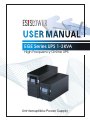
EGE Series UPS 1-3KVA
High Frequency Online UPS
Uninterruptible Power Supply
TABLE OF CONTENTS
1. Safety Instructions
1.1 Transport
1.2 Set-Up
1.3 Installation
1.4 Operation
1.5 Maintenance, Servicing and Faults
2. Commonly Used Symbols
3. Introduction
4. Panel Description
5. Connection and Operation
5.1 Inspection
5.2 Connection
5.3 Battery Charging
5.4 Turning On the UPS
5.5 Test Function
5.6 Turning Off the UPS
6. UPS Operating Modes
6.1 Line Mode of Operation
6.2 Battery Mode of Operation
6.3 Bypass Mode of Operation
6.4 No-Output Mode of Operation
6.5 Abnormal Mode of Operation
7. Setting the UPS Parameters
8. Troubleshooting
9. Maintenance
9.1 Operation
9.2 Storage
10. Technical Specifications
10.1 Electrical Specifications
10.2 Operating Environment
10.3 Typical Battery Backup Times
10.4 Dimensions and Weights
10.5 Safety and EMC Standards
11. Communication Port
11.1 RS232 Interface
11.2 AS400 Interface (optional)
12. Software For All Models
Appendix 1 - UPS Rear Panel
1. Safety Instructions
Please read the following user manual and safety instructions before
installing this unit and starting it up.
1.1 Transport
★ Please transport the UPS system in its original packing carton (to
protect it against damage due to shock and impact).
1.2 Set-up
★ As condensation may occur if the UPS is moved directly from cold to
warm environment, and in order to dry the UPS before installation,
please allow acclimatization time of at least two hours.
★ Do not install the UPS system near water sources or in dump
environment.
★ Do not install the UPS where it could be exposed to direct sunlight or
near heat.
★ Do not block off the ventilation openings of the UPS cabinet.
1.3 Installation
★ Do not connect appliances or items of equipment, which may overload
the UPS (such as laser printers), to the output of the UPS.
★ Place the cables in such a way that no one can step on or trip over
them.
★ Do not connect home appliances, such as hair-dryers, to the output of
the UPS.
★ This UPS can be operated by any individual with no previous
experience.
★ Connect the UPS only to an earthed shock-proof socket outlet.
★ The socket outlet, to which the UPS is connected, must be easily
accessible and close to the UPS.
★ Use only VDE-tested, CE-marked cable (as the power cable of your
computer) to connect the UPS to the building socket outlet.
★
Use only VDE-tested, CE-marked power cables to connect the loads
to the UPS.
★ This UPS is an operator installable.
★
When installing the equipment, it should be ensured that the sum of
the earth leakage current from the UPS and the load connected to it
must not exceed 3.5mA
1.4 Operation
★ Do not remove or unplug the input cord when the UPS is turned on.
This removes the safety ground from the UPS and the equipment
connected to the UPS.
★ This UPS contains its own energy source (batteries). The output of the
UPS may carry live voltage even when the UPS is not connected to an
AC supply.
★ For complete disconnection of the UPS system first press the "OFF"
button for more than one second, then disconnect the mains power
supply cable.
★ Ensure that no fluids or other foreign objects can enter the UPS system.
★ This UPS operates with hazardous voltages, repairs must be carried
out only by qualified service technician.
1.5 Maintenance, servicing and faults
★ This UPS operates with hazardous voltages, repairs must be carried
out only by qualified maintenance technician.
★
Caution – risk of electric shock. Even after the UPS has been
disconnected from the mains supply (building socket outlet),
dangerous high voltages are still existing inside the UPS.
★ Before carrying out any type of servicing and repair, disconnect the
mains supply and the batteries. Verify that no hazardous voltage exists
on the terminals of the capacitors.
★ Only persons, adequately familiar with batteries and with the required
precautionary measures my replace the UPS batteries, unqualified
persons must not deal with batteries.
★ Caution – risk of electric shock. The battery circuit is not isolated from
the input voltage. Hazardous voltages may occur between the battery
terminals and the ground. Before touching any terminal or wire, please
verify that no voltage is present.
★ Batteries can present a risk of electrical shock and have high shortcircuit current. The following precautions, and any others necessary
measures, should be observed:
- Remove watches, rings, or other metal objects.
- Use tools with insulated handles.
★ Replace the batteries with the same number and type, as the originally
installed ones.
★ Do not dispose of the batteries in a fire. Batteries may explode.
★ Do not open or destroy the battery. Released electrolyte is harmful to
skin and eyes. It may be toxic.
★ When replacing a fuse, use only one of the same type and the same
current and voltage ratings, as the original fuse.
★
Do not dismantle the UPS system.
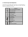
2. Commonly Used Symbols
The following are the symbols used in this manual, or on the UPS system, to
alert you to important information. Users should be familiar with these
symbols and understand their meanings.
Symbol
Explanation
Caution – Special Attention is Required.
Risk of Electric Shock.
Turning ON the UPS.
Turning OFF the UPS.
Idle or Shutdown.
Alternating Current (AC).
DC Current (DC).
Protective Ground.
Alarm Silence.
Overload Indication.
Battery Check.
Recycle.
Keep UPS in a Clean Area.
3. Introduction
This on-line UPS incorporates the latest in double-conversion topology, which
provides perfect protection for your critical and power supply sensitive
equipment specially Novell, Windows NT and Unix servers.
The double-conversion principle eliminates all the mains power disturbances.
Here, a rectifier converts the alternating current of the mains supply to direct
current. This direct current charges the batteries and powers the inverter. The
inverter, in its turn, generates a sinusoidal AC voltage, which permanently
supplies the loads with uninterrupted, clean and sine-wave voltage.
Computers and peripherals are thus powered entirely by the inverter. In the
event of mains power failure, the maintenance-free batteries supply the
inverter.
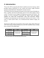
This series of UPS units are produced in three power ratings 1kVA, 2kVA and
3kVA with standard battery backup time and with extended battery backup
time, as shown in the table below.
UPS Model
Type
EGE-103KT
Type
EGE-101KTL
EGE-101KT
EGE-102KT
UPS Model
Standard battery
backup time
EGE-102KTL
EGE-103KTL
“L ” denotes models with extended battery backup times
Extended battery
backup time
4. Panel Description
.
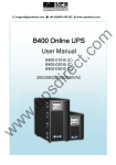
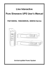
Fig. 4.1: Front panel of the UPS
The following table describes the function of the button switches of the front
panel.
Switch
ON-Button/
Alarm Silence
Function
This button has two functions:
- Turning on the UPS system: By pressing this button, the UPS
system turns on.
- Deactivating the audible alarm: By pressing this button the
audible alarm can be deactivated.
OFF-Button
By pressing the "OFF" button “ “, the inverter turns off and, if the
mains power supply is normal, the UPS system switches to Standby
or Bypass mode. The UPS output sockets will be supplied via the
bypass circuit.
Select-Button
If the UPS is in the Bypass or in the No-output mode, this button is
used to enter the configuration mode and to select the UPS output
voltage and frequency and to disable or enable the bypass circuit.
Enter-Button
If the UPS is in the Bypass or in the No-output mode, this button is
used to confirm the selected UPS output voltage and frequency and
the disabling/enabling state of the bypass circuit.
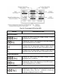
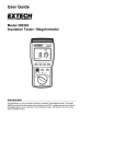
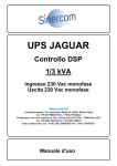
Fig. 4.2: Front panel LCD of the UPS
Display
Information or Data
Input Information
Displays the value of the input supply voltage. It can be
displayed from 0 to 999Vac.
Displays the value of the frequency of the input supply. It
can be displayed from 0 to 99Hz.
Indicates that the input supply voltage is higher than the
specified range, the UPS will work in the battery mode.
Indicates that the input supply voltage is lower than the
specified range, the UPS will work in the battery mode.
Output Information
Displays the value of the UPS output voltage. It can be
displayed from 0 to 999Vac.
Displays the value of the frequency of the UPS output. It
can be displayed from 0 to 99Hz.
Load Information
Displays the load in Watt or VA as a percent of the UPS
output power rating. Only the maximum of these two
readings is displayed from 0 to 199%.
Indicates that the load or the UPS output is shortcircuited and the UPS will shutdown.
Indicates that the load is higher than the UPS output
power rating.
Battery Information
Displays the value of the battery voltage. It can be
displayed from 0 to 999Vdc.
Displays the battery stored capacitance in percent. It can
be displayed from 0 to 199%.
Indicates that the battery is over charged, the UPS will be
switched to battery mode.
Indicates that the battery voltage is low, the UPS will
shutdown soon.
Mode/Fault/Warning code Information
Displays the operating mode, the fault code and the
warning codes of the UPS. For the meaning of these
codes refer to page 13.
Inverter operating Information
Indicates that the inverter is running.
Bypass operating Information
Indicates that the bypass circuit is running.
Output voltage and frequency and Bypass disable/enable selection Information
Indicates the value of the desired UPS output voltage.
One of these four values can be selected when the UPS
is in the No-output or in the Bypass mode.
Indicates the value of the desired UPS output frequency.
One of these two values can be selected when the UPS
is in the No-output or in the Bypass mode.
Indicates if the Bypass circuit is going to be disabled or
enabled. One of these two states can be selected when
the UPS is in the No-output or in the Bypass mode.
5. Connection and Operation
This UPS system has to be wired and installed by a qualified
technician and in accordance with the applicable safety
regulations.
When installing the electrical wiring of the UPS, please take
into consideration the rated current-carrying capacity
( ampacity ) of the incoming feeder.
5.1 Inspection: Inspect the packing carton and its contents for any damage.
Inform the carrier agency immediately if you find any sign of damage.
Keep the packing cartons in a safe place for future use.
Note: Please ensure that the incoming feeder is isolated and secured
to prevent it from being switched on again.
5.2 Connection
5.2.1 UPS Input Connection
The current carrying capacity (ampacity) of the socket outlet, to which the
UPS is connected, must be greater than the UPS input current: over 10A
for 1KT, 1KT-XLand 2KT models and over 16A for 2KT-XL, 3KT and 3KT-XL
models.
5.2.2 UPS Output Connection
The outputs of the UPS EGE-101KT(L);EGE-102KT(L);EGE-103KT(L) are
socket type only. Simply plug the load power cord to the UPS output socke
to complete the connection.
UPS Model
Number of Socket Outlets
Output Terminal Block
EGE-101KT(L)
2
No
EGE-102KT(L)
2
No
EGE-103KT(L)
3
No
Caution!
* Do not connect equipment (such as printers), which may overload the
UPS system.
5.3 Battery Charging
To fully charge the batteries of the UPS, keep the UPS connected to the mains
supply for 1-2 hours. During this period, the UPS can be used to supply the
load, but in this case the battery autonomy time will be less than the values
specified.
5.4 Turn ing On the UPS
5.4.1 With Mains Power Connected
Press the "ON" button " " continuously for more than one second, to turn
on the UPS. At the beginning of the turning-on process the UPS performs
a self-test. After finishing the self-test, the inverter starts and the UPS
becomes in the line-mode. The LCD screen lights up to indicate the status
of the UPS.
5.4.2 Without Mains Power Connected
Even the mains power supply is not connected, pressing the "ON" button
" " continuously, for more than one second, will turn on the UPS. At the
beginning of the turning-on process the UPS performs a self-test. After
finishing the self-test the inverter starts and the UPS becomes in the
battery-mode. The LCD screen lights up and indicates the status of the UPS.
Note: The default setting for the bypass circuit is the no-output state.
This state can be configured using the front panel button switches or
software.
5.5 Test Funct ion
To test the UPS press the "ON" button " " of the UPS or disconnect the input
mains supply.
5.6 Turn ing Off the UPS
5.6.1 In Line Mode
Press the "OFF" button “ " continuously for more than one second. At the
beginning, the UPS performs a self-test. After finishing the self-test, the
UPS becomes in the standby or the bypass-mode. A voltage may exist at
the output of the UPS if the bypass is enabled. Disconnect the mains
power to remove the UPS output voltage.
5.6.2 In Battery Mode
To turn off the UPS, press the "OFF" button “ " continuously for more than
one second. At the beginning of the turning-off process the UPS performs
5.6.2 In Battery Mode
To turn off the UPS, press the "OFF" button “ " continuously for more than
one second. At the beginning of the turning-off process the UPS performs
a self-test. After the self-test is finished the UPS turns off completely.
5.7 Audible Alarm m ute
If the alarm is activating in the battery mode, press the "ON" button " "
continuously, for more than one second, to clear it. The alarm will be
activated again when the battery voltage becomes low to remind you to
shutdown the load.
5.8 Procedure of external battery connection for long backup time
models ("S" models).
●
Units with CE marks
1) Use the battery pack of 36VDC (3 cells of 12V each) for the 101KTL models
Use the battery pack of 96VDC (8 cells of 12V each) for the 102KTL
and 103KTL models. Connection of battery packs with wrong battery
voltages will cause damage.
2) One end of the external battery cable will be plugged into the external
battery socket of the UPS and the other end will be connected to the
external battery cabinet.
3) Do not connect any load to the UPS output. Connect the input power cable
of the UPS to the input mains supply to operate the UPS in the utility
power mode.
4) Connect the external battery cable between the external battery socket, on
the rear panel of the UPS, and the external battery cabinet. The UPS will
start charging the external battery.
5) This external battery cable has three wires, the red is the "+" wire, the
black is the "-" wire and the green/yellow is the grounding wire.
Caution!
The output sockets of the UPS system may carry live voltage even if the
input power supply has been disconnected or the bypass switch is on
“OFF” position.
6. UPS Operating Modes
On the LCD panel of the UPS, a code is displayed to indicate the operating
mode of the UPS. The codes displayed can also indicate a fault or a warning.
The table below shows the meanings of the different codes that can be
displayed on the UPS LCD.
Note that, at any time instant, only one operating mode or a fault mode can
be represented.
If several warnings exist in a given operating mode, the codes of these
warnings and the code that indicates the operating mode are shown cyclically.
Once a fault comes forth, the codes of all existing warnings will not be
displayed and only the code of the existing fault will be displayed.
Operating mode
code
Operating mode
code
No-output mode
00
Overload fault
07
Bypass mode
01
Over temperature fault
08
Line mode
02
Site fail warning
09
Battery mode
03
Fan fail warning
10
Battery test mode
04
Battery over-charge warning
11
Bus fault
05
Battery weak warning
12
Inverter fault
06
Charger fail warning
13
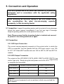
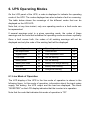
6.1 Line Mode of Operation
The LCD display of the UPS in the line mode of operation is shown in the
following figure. In this mode of operation, information about the input mains
supply, the battery, the UPS output and the load are displayed. The block
"INVERTER" on the LCD display indicates that the inverter is in operation.
Note that the code that indicates this mode of operation is "02".
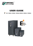
Fig. 6.1: Line mode of operation
If the UPS becomes overloaded, the percentage of the load will be shown
and the audible alarm will beep twice per second. In this case, the UPS load
has to be decreased to less than 90% of its rated power capacity.
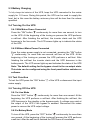
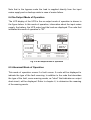
6.2 Battery Mode of Operation
The LCD display of the UPS in the battery mode of operation is shown in the
figure below. In this mode of operation, information about the input mains
supply, the battery, the UPS output and the load are displayed. The block
"INVERTER" on the LCD display indicates that the inverter is in operation.
Note that:
1) When the UPS is in the battery mode, the alarm beeps once every
4 seconds. To silence the alarm, press the "ON" button for more
than one second. Pressing the "ON" button again for more than one
second resumes the alarm again.
2) If the mains input supply voltage becomes higher than the
maximum input voltage accepted by the UPS, the "H" sign will be
shown on the LCD, while if the mains input supply voltage becomes
lower than the minimum input voltage accepted by the UPS, the "L"
sign will be shown on the LCD.
If the input mains supply is lost, both "H" and "L" signs will
disappear and the input voltage and frequency will display zeros.
Fig. 6.2: Battery mode of operation
The display of battery test mode is the same as battery mode, but “H” and “L”
signs will not be shown unless the input mains voltage is higher or lower than
the values accepted by the UPS.
The code that indicates the battery mode of operation is "03" while the code
that indicates the battery test mode is "04".
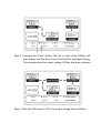
6.3 Bypass Mode of Operation
The LCD display of the UPS in the bypass mode of operation is shown in the
figure below. In this mode of operation, information about the input mains
supply, the battery, the UPS output and the load are displayed. The code that
indicates this mode of operation is "01". The block "BYPASS" on the LCD
display indicates that the bypass circuit is in operation. The UPS alarm beeps
once every two minutes.
Fig. 6.3: Bypass mode of operation
Note that in the bypass mode the load is supplied directly from the input
mains supply and no backup exists in case of mains failure.
6.4 No-Output Mode of Operation
The LCD display of the UPS in the no-output mode of operation is shown in
the figure below. In this mode of operation, information about the input mains
supply, the battery, the UPS output and the load are displayed. The code that
indicates this mode of operation is "00".
Fig. 6.4: No-output mode of operation
6.5 Abnormal Mode of Operation
This mode of operation occurs if a fault occurs. A code will be displayed to
indicate the type of the fault occurring. In addition to the code that describes
the type of the fault, some warning words, as "short" that indicates an output
short-circuit, will be displayed. Refer to chapter 4, to determine the meaning
of the warning words.
7. Setting The UPS Parameters
The front panel button switches are used to set the UPS output voltage and
frequency and to disable or enable the bypass circuit. The UPS output
voltage can be set to 208VAC, 220VAC, 230VAC or 240VAC. The UPS
output frequency can be set to 50Hz. or 60Hz. The UPS bypass circuit can
be set to enable or disable state.
Note that these parameters can be set only when the UPS is in the bypass or
in the no-output mode.
While the UPS is in the bypass or in the no-output mode, if the "Select" button
is pressed for more than one second, a flickering black round dot will be
shown in front of the "208V" on the LCD. If the "Select" button is again
pressed continuously, the flickering dot will move to the front of the "220V",
"230V", "240V", "50Hz", "60Hz", "Bypass Disable" and "Bypass Enable"
cyclically.
To select any of these possible choices, press the "Enter" button for more
than one second.
The output voltage and frequency of the UPS will be changed to the selected
value after the UPS is turned on, by pressing the "ON" button.
If the "Bypass Enable" was selected, The UPS will turn to bypass mode, in
several seconds. While if "Bypass Disable" was selected, the UPS will turn to
"No Output" mode.
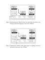
The following figures show the steps required to change the UPS output
voltage from 220V to 230V.
Step 1. After pressing the “Select” button, for more than one second, one
flicking round dot will appear in front of the “208Vac”.
Step 2. Pressing the “Select” button twice again, the flicking round dot
will move to the front of the “230Vac”
Step 3. Pressing the “Enter” button, the dot in front of the 230Vac will
stop flicking, and the dot in front of the 240Vac will begin flicking.
This indicates that the output voltage 230Vac has been selected.
Step 4. After the UPS turns to “ON”, the output voltage will be 230Vac.
8. Troubleshooting
If the UPS alarm is activated, use the following table to determine and resolve
the problem.
Problem
Possible Cause
Action
Even the UPS is
connected to the mains
power supply, there are
no warning tones and
no indications are
shown on the LCD
panel.
No input supply
voltage.
Check building wiring
socket outlet and the UPS
input cable.
Warning code 09 is
shown on the LCD
panel.
Phase and neutral
conductors of the
UPS input are
reversed
Rotate mains power socket
by 180°.
Mode code 03 is shown
on the LCD panel, and
the warning word “H” or
“L” may be also
displayed
Input power supply
voltage and/or
frequency is out of
tolerance
Check the input power
supply source and inform
the service representative,
if necessary.
Even the mains power
supply is available,
mode code 00 or 01 is
shown on the LCD
panel.
Inverter is not
switched on.
Press the "ON" switch.
Mode code 03 is shown
on the LCD panel, the
alarm beeps 1 beep
every 4 seconds.
The UPS is in the battery
Mains power supply mode. When audible alarm
failure
beeps once per second the
battery is almost empty.
Fault code 07 is shown
on the LCD panel, the
alarm beeps once per
second.
Remove some of the loads
from the UPS output and
restart.
Overload
Fault code 05 or 06 or
08 is shown on the LCD
panel, the alarm beeps
continuously.
UPS fault
Contact the service
representative.
Battery backup time is
shorter than nominal
value.
Battery not fully
charged or battery
faulty.
Charge the battery for at
least 1 - 2 hours and then
check battery backup time.
Contact the service
representative.
Warning code 13 is
shown on the LCD
panel, the alarm beeps
once per second.
Charger or Battery
faulty
Contact the service
representative.
Warning code 10 is
shown on the LCD
panel
Fan is locked or not Check fan(s) and contact
working.
the service representative.
Please have the following information ready when you call the after-Sales
Service Department:
• Model number and serial number
• Date of failure or problem
• Symptoms of failure or problem
9. Maintenance
9.1 Operation
Please note that this UPS has no user-serviceable parts inside. If the battery
service life (3 to 5 years at 25°C ambient temperature) has been exceeded,
the batteries have to be replaced. For battery replacement, contact your
dealer.
9.2 Storage
If the UPS is stored in a temperate climatic environment, recharge the battery
every three months by connecting the UPS to the mains power supply for a
period of one to two hours. You should shorten the charging intervals to two
months at locations subject to high temperatures.
10. Technical Specifications
10.1 Electrical specifications
Electrical input
Mode No.
l
EGE-101KTL EGE-102KT EGE-102KTL EGE-103KTL
Phase
Single
Frequency
(46~54)/(56~64) Hz
Current(A)
7A
9A
12A
16A
Electrical output
Model No.
EGE-101KTL
EGE-102KTL
EGE-103KTL
Power rating
1kVA/0.7kW
2kVA/1.4kW
3kVA/2.1kW
208/220/230/240 ( ± 2%) VAC
Voltage
Frequency
50/60 (±0.2) Hz (Battery mode)
Waveform
sinusoidal
Note: The output power of the UPS is de-rated to 90% of its
nominal value, when the output voltage of the UPS is adjusted
to 208V.
Batteries
Model No.
101KT
102KT
103KT
Number and type
3×12V×7.2Ah
8×12V×7.2Ah
8×12V×7.2Ah
10.2 Operating Environment
Operating Temperature
0°
C to 40°
C
Operating humidity
< 95%
Operating Altitude
< 1000m
Storage temperature
0°
C ~ 40°
C
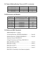
10.3 Typical Battery Backup Times (at 25°C, in minutes)
Model No.
100 % Load
50 % Load
EGE-101KT
5
14
EGE-102KT
9
21
EGE-103KT
5
15
10.4 Dimensions and Weights
Model No.
Dimensions W x D x H (mm)
Net Weight kg
EGE-101KT
145X400X220
14
EGE-101KTL
145X400X220
7
EGE-102KT
192X460X340
34.5
EGE-102KTL
192X460X340
15
EGE-103KT
192X460X340
35.5
EGE-103KTL
192X460X340
16
10.5 Safety and EMC Standards
GB4943/EN62040-1-1 (safety)
Conducted Emission: GB7260.2/EN62040-2............. Class B
Radiated Emission: GB7260.2/EN62040-2................ Class B
Harmonic Current: EN61000-3-2
Voltage Fluctuations and Flicker: EN61000-3-3
EMS: EN61000-4-2 (ESD)........................................... Level 4
EN61000-4-3 (RS) ...................................................... Level 3
EN61000-4-4 (EFT) ..................................................... Level 4
EN61000-4-5 (Surge) .................................................. Level 4
EN61000-2-2 (Immunity to low frequency signals)
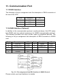
11. Communication Port
11.1 RS232 Interface
The following is the pin assignment and the description of DB-9 connector at
the rear of the UPS.
Pin #
Description
I/O
2
TXD
Output
3
RXD
Input
5
GND
Input
11.2 AS400 Interface (Optional)
In addition to the communication protocol, mentioned above, this UPS series
has AS400 card (an optional accessory) for AS400 communication protocol.
This interface provides true relay contact output to peripheral devices. The
following is the pin assignment and description of DB-9 connector in AS400
card.
Pin #
Description
I/O
Pin #
Description
I/O
1
UPS Fail
Output
6
Bypass
Output
2
Summary Alarm
Output
7
Battery Low
Output
3
GND
Input
8
UPS ON
Output
4
Remote Shutdown
Input
9
Line Loss
Output
5
Common
Input
Fig. 10.1: Pin assignment of the DB-9 interface of AS400 Protocol
Please contact your local distributor for details.
12. Software For All Models
The Free-downloaded Software-WinPower.
WinPower is a brand new UPS monitoring software, which provides a userfriendly interface to monitor and control your UPS. This unique software
provides safely auto shutdown for multi-computer systems in case of power
failure. With this software, you can monitor and control any of your UPS
systems on the same LAN, no matter how far are these UPS systems.
W
Installation Procedure:
The following is the installation procedure for the WinPower software:
1. Connect to the website:
http://www.ups-software-download.com/winpower.htm
2. From the different choices mentioned in this web page, select the operating
system you are using and follow the instructions described on the website
to download the software.
3. When downloading is finished, enter the serial number 511C1-01220-0100478DF2A, to install the software.
When your computer restarts, the WinPower software will appear as a green
icon located in the system task manager, near the clock.
Appendix 1 - UPS Rear Panel
The rear panel of the EGE 101KT and EGE 101KTL models
The rear panel of the EGE 102KT/EGE 102KTL and EGE 103KT/EGE103KTL models
ESIS ENERJI VE ELEKTRONIK SAN. TIC.A.S.
Dudullu Organize Sanayi Bolgesi Esenkent Mah.
Baturalp Sok.No:14 Umraniye / İSTANBUL
Tel : +90 216 540 90 00
Fax: +90 216 540 90 10
E-mail: [email protected]