1
FORKLIFT SAFETY
CONTENTS
MANITOU NORTH AMERICA, INC.
6401 IMPERIAL DRIVE
Waco, TX 76712--6803
For Parts Orders contact your Manitou North America Dealer or call:
Manitou North America, Parts Dept. 800--425--3727 or (254) 799--0232
Parts Dept. Fax: (254) 867--6504
Website: www.manitou--na.com
CALIFORNIA PROPOSITION 65 WARNING
Diesel Engine Exhaust and some of its constituents are known to the State of
California to cause cancer, birth defects or other reproductive harm.
MSI 20/25/30 D
MSI 20/25/30 D BUGGIE
S/N: 121128 to 203025
OPERATOR’S MANUAL
THIS OPERATOR’S MANUAL MUST BE KEPT IN THE LIFT TRUCK. IT MUST BE READ AND
UNDERSTOOD BY THE LIFT TRUCK OPERATOR.
CATALOG 547041AS
R11--10
FORKLIFT SAFETY
CONTENTS
FORKLIFT SAFETY
CONTENTS
- INTRODUCTION TO SAFETY -
- ROUGH TERRAIN FORKLIFT TRUCK
GENERAL SAFETY STANDARDS - - - I
- SAFTETY MESSAGES - - - - - - - - - - - - - - - - - - - - - - - - - - VII
- SAFETY DECALS - - - - - - - - - - - - - - - - - - - - - - - - - - - - - - VIII
- TABLE OF CONTENTS - - - - - - - - - - - - - - - - - - - - - - - - - - XV
R03-04
FORKLIFT SAFETY
CONTENTS
FORKLIFT SAFETY
CONTENTS
ROUGH TERRAIN FORKLIFT TRUCK
GENERAL SAFETY STANDARDS
I
FORKLIFT SAFETY
CONTENTS
ROUGH TERRAIN FORKLIFT TRUCK GENERAL SAFETY STANDARDS
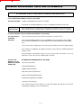
STUDY THE OPERATOR/SERVICE MANUALS
The information in this manual provides general instructions for the safe operation and maintenance of your
forklift truck. This information is vital and must be clearly understood by the operator and serviceman. Study
this manual and the Rough Terrain Forklift Safety Manual (part no. 422494) thoroughly and carefully before
operating or servicing your forklift. Contact your dealer or Manitou North America, Inc. if you have any questions concerning your forklift, its operation, service or parts. Keep both manuals in the literature box on the
forklift available for reference. If either manual becomes illegible or is missing, contact your dealer for replacements immediately. This manual cannot cover every situation that might result in an accident. It is the responsibility of the operator to always remain alert for potential hazards and be prepared to avoid them!
ADDITIONAL RECOMMENDED LITERATURE:
ANSI / ITSDF B56.6 is the national consensus standard for rough terrain forklift trucks. It contains rules about
forklift safety, maintenance, safe operation, training, and supervision. Forklift owners should learn this standard and make it available for their operators, service personnel, and supervisors. These standards can be
obtained, free of charge, from the Industrial Truck Standards Development Foundation (ITSDF) on their website at www.itsdf.org. The following references are examples from the standard, addressing forklift operators:
A.) OPERATOR TRAINING QUALIFICATIONS
1.) The user shall ensure that operators understand that safe operation is the operator’s responsibility. The
user shall ensure that operators are knowledgeable of, and observe, all safety rules and practices.
2.) Create an effective operator training program centered around user company’s policies, operating conditions, and rough terrain forklift trucks. The program should be presented completely to all new operators and
not be condensed for those claiming previous experience.
3.) Information on operator training is available from several sources, including rough terrain forklift truck manufacturers, users, government agencies, etc.
4.) An operator training program should consist of the following:
a.) careful selection of the operator, considering physical qualifications, job attitude, and aptitude;
b.) emphasis on safety of stock, equipment, operator, and other personnel;
c.) citing of rules and why they were formulated;
d.) basic fundamentals of rough terrain forklift truck and component design as related to safety, e.g.,
in.-lb (N-m) loading, mechanical limitations, center of gravity, stability, etc.;
e.) introduction to equipment, control locations, and functions. Explain how they work when used
properly and problems when used improperly.
f.) supervise practice on operating course remote from normal activity and designed to simulate
actual operations, e.g., lumber stacking, elevating shingles to the roof, etc.;
g.) oral, written, and operational performance tests and evaluations during and at completion of the
course;
h.) refresher courses, which may be condensed versions of the primary
course, and periodic “on job” operator evaluation;
i.) understanding of nameplate data and operator instructions and warning information appearing on
the rough terrain forklift truck.
B.) GENERAL SAFETY PRACTICES
1.) Rough terrain forklift trucks can cause injury if improperly used or maintained.
2.) Only authorized operators trained to adhere strictly to all operating instructions shall be permitted to operate rough terrain forklift trucks. Unusual operating conditions may require additional safety precautions, training, and special operating instructions.
3.) Modifications and additions which affect capacity or safe operation shall not be preformed without the manufacturer’s prior written approval. Where such authorization is granted, capacity, operation, and maintenance
instruction plates, tags, or decals shall be changed accordingly.
4.) If the rough terrain forklift truck is equipped with front end attachment(s) or optional forks, the user shall see
that the truck is marked to identify the forks or attachment(s), show the approximate weight of the truck and
fork or attachment combination, and show the capacity of the truck with forks or attachment(s) at maximum
elevation with load laterally centered.
5.) The user shall see that all nameplates and caution and instruction markings are in place and legible.
6.) The user shall consider that changes in load dimension may affect rough terrain forklift truck capacity.
II
FORKLIFT SAFETY
CONTENTS
ROUGH TERRAIN FORKLIFT TRUCK GENERAL SAFETY STANDARDS (cont.)
B.) GENERAL SAFETY PRACTICES (cont.)
7.) Where steering can be accomplished with either hand and the steering mechanism is of a type that prevents road reactions from causing the handwheel to spin (power steering or equivalent), steering knobs may
be used. When used, steering knobs shall be of a type that can be engaged by the operator’s hand from the
top and shall be within the periphery of the steering handwheel.
8.) Experience has shown that rough terrain forklift trucks which comply with stability requirements are stable
when properly operated. However, improper operation, faulty maintenance, or poor housekeeping may contribute to a condition of instability and defeat the purpose of the requirements.
9.) Users shall give consideration to special operating conditions. The amount of forward and rearward tilt to
be used is governed by the application. Although the use of maximum rearward tilt is allowable under certain
conditions, such as traveling with the load lowered, the stability of a rough terrain forklift truck as determined
by standardized tests does not encompass consideration for excessive tilt at high elevations or the operation
of trucks with excessive off-center loads.
10.) Some of the conditions which may affect stability are ground and floor conditions, grade, speed, loading
(rough terrain forklift trucks equipped with attachments behave as partially loaded trucks even when operated
without a load on the attachment), dynamic and static forces, improper tire inflation, and the judgement exercised by the operator.
C.) OPERATING SAFETY RULES AND PRACTICES
1.) Safe operation is the responsibility of the operator.
2.) This equipment can be dangerous if not used properly. The operator shall develop safe working habits and
also be aware of hazardous conditions in order to protect himself, other personnel, the rough terrain forklift
truck, and other material.
3.) The operator shall be familiar with the operation and function of all controls and instruments before undertaking to operate the rough terrain forklift truck.
4.) Before operating any rough terrain forklift truck, truck operators shall have read and be familiar with the
operator’s manual for the particular truck being operated.
5.) Before starting to operate the rough terrain forklift truck:
a.) be in operating position and fasten seat belt;
b.) place directional controls in neutral;
c.) apply brakes;
d.) start engine.
6.) Do not start or operate the rough terrain forklift truck, any of its functions, or attachments from any place
other than the designated operator’s position.
7.) Keep hands and feet inside the operator’s designated area or compartment. Do not put any part of the
body outside the operator compartment of the rough terrain forklift truck.
8.) Never put any part of the body into the mast structure or between the mast and the rough terrain forklift
truck.
9.) Never put any part of the body within the reach mechanism of the rough terrain forklift truck or other attachments.
10.) Understand rough terrain forklift limitations and operate the truck in a safe manner so as not to cause injury
to personnel.
11.) Do not allow anyone to stand or pass under the elevated portion of any rough terrain forklift truck, whether
empty or loaded.
12.) Do not permit passengers to ride on rough terrain forklift trucks.
13.) Check clearance carefully before driving under electrical lines, bridges, etc.
14.) A rough terrain forklift truck is attended when the operator is less than 25 ft (7.6m) from the truck, which
remains in his view.
15.) A rough terrain forklift truck is unattended when the operator is 25ft (7.6m) or more from the truck, which
remains in his view, or whenever the operator leaves the truck and it is not in his view.
16.) Before leaving the operator’s position:
a.) bring rough terrain forklift truck to a complete stop;
b.) place directional controls in neutral;
c.) apply the parking brake;
d.) lower load-engaging means fully, unless supporting an occupied elevated platform;
e.) stop the engine;
f.) if the rough terrain forklift truck must be left on an incline, block the wheels;
g.) fully lower the load-engaging means.
17.) Maintain a safe distance from the edge of ramps, platforms, and other similar working surfaces.
18.) Do no move railroad cars or trailer with a rough terrain forklift truck.
III
FORKLIFT SAFETY
CONTENTS
ROUGH TERRAIN FORKLIFT TRUCK GENERAL SAFETY STANDARDS (cont.)
C.) OPERATING SAFETY RULES AND PRACTICES (cont.)
19.) Do not use a rough terrain forklift truck for opening or closing railroad car doors.
20.) In areas classified as hazardous, use only rough terrain forklift trucks approved for use in those areas.
21.) Report all accidents involving personnel, building structures, and equipment to the supervisor or as
directed.
22.) Do not add to, or modify, the rough terrain forklift truck.
23.) Do not block access to fire aisles, stairways, and fire equipment.
24.) For rough terrain forklift trucks equipped with a differential lock, the lock should not be engaged when driving on the road or at high speeds or when turning. If the lock is engaged when turning, there could be loss of
steering control.
25.) Observe all traffic regulations including authorized speed limits. Under normal traffic conditions, keep to
the right, maintain a safe distance, based on speed of travel, from the truck ahead; and keep the truck under
control at all times.
26.) Yield the right-of-way to pedestrians and emergency vehicles such as ambulances and fire trucks.
27.) Do not pass another truck traveling in the same direction at intersections, blind spots, or at other dangerous locations.
28.) Slow down and sound the audible warning device(s) at cross-aisles and other locations where vision is
obstructed.
29.) Cross railroad tracks at an angle wherever possible. Do not park closer than 6 ft (1.8m) to the nearest rail
of a railroad track.
30.) Keep a clear view of the path of travel and observe other traffic, personnel, and safe clearances.
31.) If the load being carried obstructs forward view, travel with the load trailing.
32.) Ascend or descend grades slowly and with caution.
a.) When ascending or descending grades in excess of 5%, loaded rough terrain forklift trucks
should be driven with the load upgrade.
b.) Unloaded rough terrain forklift trucks should be operated on all grades with the load-engaging
means downgrade.
c.) On all grades, the load and load-engaging means shall be tilted back, if applicable, and raised
only as far as necessary to clear the road surface.
d.) Avoid turning, if possible, and use extreme caution on grades, ramps, or inclines; normally
travel straight up or down.
33.) Under all travel conditions, operate the rough terrain forklift truck at a speed that will permit it to be brought
to a stop in a safe manner.
34.) Travel with load-engaging means or load low and, where possible, tilted back. Do not elevate the load
except during stacking.
35.) Make starts, stops, turns, or direction reversals in a smooth manner so as not to shift load and/or overturn
the rough terrain forklift truck.
36.) Do not indulge in stunt driving or horseplay.
37.) Slow down for wet and slippery surfaces.
38.) Before driving over a dockboard or bridge plate, be sure that it is properly secured. Drive carefully and
slowly across the dockboard or bridge plate, and never exceed its rated capacity.
39.) Do not drive rough terrain forklift trucks onto any elevator unless specifically authorized to do so.
Approach elevators slowly, and then enter squarely after the elevator car is properly leveled. Once on the elevator, neutralize the controls, shut off engine, and set brakes. It is advisable that all other personnel leave the
elevator before truck is allowed to enter or leave.
40.) Avoid running over loose objects on the roadway surface.
41.) When negotiating turns, reduce speed to a safe level, and turn steering handwheel in a smooth sweeping
motion. Except when maneuvering at a very low speed, turn the steering handwheel at a moderate, even rate.
42.) Use special care when traveling without load, as the risk of lateral overturning is greater.
43.) Improper use of stabilizer controls (if so equipped) could cause rough terrain forklift truck upset. Always
lower the carriage before operating stabilizer controls.
44.) For rough terrain forklift trucks equipped with lateral leveling:
a.) Always level the frame before raising the boom or mast, with or without a load.
b.) Lateral leveling should not be used to position an elevated load; instead, lower the load and
reposition the rough terrain forklift truck.
45.) Handle only stable or safely arranged loads.
a.) When handling off-center loads which cannot be centered, operate with extra caution.
b.) Handle only loads within the capacity of the rough terrain forklift truck.
c.) Handle loads exceeding the dimensions used to establish rough terrain forklift truck capacity
with extra caution. Stability and maneuverability may be adversely affected.
IV
FORKLIFT SAFETY
CONTENTS
ROUGH TERRAIN FORKLIFT TRUCK GENERAL SAFETY STANDARDS (cont.)
C.) OPERATING SAFETY RULES AND PRACTICES (cont.)
46.) When attachments are used, extra care shall be taken in securing, manipulating, positioning, and transporting the load. Operate rough terrain forklift trucks equipped with attachments as partially loaded trucks
when not handling a load.
47.) Completely engage the load with the load-engaging means. Fork length should be at least two-thirds of
load length. Where tilt is provided, carefully tilt the load backward to stabilize the load. Caution should be used
in tilting backward with high or segmented loads.
48.) Use extreme care when tilting load forward or backward, particularly when high tiering. Do not tilt forward
with load-engaging means elevated except to pick up or deposit a load over a rack or stack. When stacking
or tiering, use only enough backward tilt to stabilize the load.
49.) The handling of suspended loads by means of a crane arm (boom) or other device can introduce dynamic forces affecting the stability of a rough terrain forklift truck. Grades and sudden starts, stops, and turns can
cause the load to swing and create a hazard if not externally stabilized. When handling suspended loads:
a.) do not exceed the truck manufacturer’s capacity of the rough terrain forklift truck as equipped
for handling suspended loads.
b.) only lift the load vertically and never drag it horizontally;
c.) transport the load with the bottom of the load and the mast as low as possible;
d.) with load elevated, maneuver the rough terrain forklift truck slowly and cautiously, and only to
the extent necessary to permit lowering to the transport position;
e.) use tag lines to restrain load swing whenever possible.
50.) At the beginning of each shift and before operating the rough terrain forklift truck, check its condition,
giving special attention to:
a.) tires and their inflation pressure
b.) warning devices
c.) lights
d.) lift and tilt systems, load-engaging means, chains, cables, and limit switches
e.) brakes
f.) steering mechanism
g.) fuel system(s)
51.) If the rough terrain forklift truck is found to be in need of repair or in any way unsafe, or if it contributes to
an unsafe condition, the matter shall be reported immediately to the user’s designated authority, and the truck
shall not be operated until it has been restored to safe operating condition.
52.) If during operation the rough terrain forklift truck becomes unsafe in any way, the matter shall be reported
immediately to the user’s designated authority, and the truck shall not be operated until it has been restored to
safe operating condition.
53.) Do not make repairs or adjustments unless specifically authorized to do so.
54.) When refueling, smoking in the area shall not be permitted, the engine shall be stopped, and the operator shall not be on the rough terrain forklift
truck.
55.) Spillage of oil or fuel shall be carefully and completely absorbed or evaporated and fuel tank cap replaced
before restarting engine.
56.) Do not use open flames when checking electrolyte level in storage batteries, liquid level in fuel tanks, or
the condition of LPG fuel lines and connectors.
57.) Do not lift personnel with the forklift. If the forklift must be used to lift people, precautions for the protection of the personnel must be taken (see ITSDF B56.6, chapter 5.15 Elevating Personnel).
V
ROUGH TERRAIN FORKLIFT TRUCK GENERAL SAFETY STANDARDS (cont.)
D.) SUSPENDED LOADS
A jib or truss boom should ONLY be used to lift and place loads when the machine is stationary and the frame
is level. Transporting suspended loads must ALWAYS be done slowly and cautiously, with the boom and load
as low as possible. Use taglines to restrict loads from swinging, to avoid overturn.
The handling of suspended loads by means of a truss boom or other similar device can introduce dynamic
forces affecting the stability of the machine that are not considered in the stability criteria of industry test
standards. Grades and sudden starts, stops and turns can cause the load to swing and create a hazard.
Guidelines for “Free Rigging / Suspended Loads”
1.
DO NOT exceed the rated capacity of the telescopic handler as equipped for handling suspended
loads. The weight of the rigging must be included as part of the load.
2.
During transport, DO NOT raise the load more than 12 inches (305 mm) above the ground, or raise
the boom more than 45 degrees.
3.
Only lift the load vertically – NEVER drag it horizontally.
4.
Use multiple pickup points on the load when possible. Use taglines to restrain the load from swinging
and rotating.
5.
Start, travel, turn and stop SLOWLY to prevent the load from swinging. DO NOT exceed walking
speed.
6.
Inspect rigging before use. Rigging must be in good condition and in the U.S. comply with OSHA
regulation §1910.184, “Slings,” or §1926.251, “Rigging equipment for material handling.”
7.
Rigging equipment attached to the forks must be secured such that it cannot move either sideways or
fore and aft. The load center must not exceed 24 inches (610 mm).
8.
DO NOT lift the load with anyone on the load, rigging or lift equipment, and NEVER lift the load over
personnel.
9.
Beware of the wind, which can cause suspended loads to swing, even with taglines.
10.
DO NOT attempt to use frame-leveling to compensate for load swing.
WARNING
U.S. OSHA regulations effective November 8, 2010 (29 CFR Part 1926, Subpart CC - Cranes and Derricks in
Construction) include requirements for employers that use powered industrial trucks ("forklifts") configured
to hoist (by means of a winch or hook) and move suspended loads horizontally. In particular, this regulation
applies to any rough-terrain forklift (e.g., "telescopic handler") equipped with a jib or truss boom with a
hook (with or without a winch), or a hook assembly attached to the forks. [Note: This regulation is in
addition to the OSHA regulation that requires specific forklift operator training: §1910.178(l).]
When a forklift / telescopic handler is configured and used for hoisting, the employer must ensure that:
1.
Forklift, lift equipment and rigging have been inspected (each shift, month and year) and are in
good, safe condition and properly installed.
2.
An operator's manual and applicable load charts are on the forklift.
3.
Work zone ground conditions can support the equipment and load. Any hazardous conditions in the
work area have been identified, and the operator notified.
4.
Equipment is being used within its rated capacity and in accordance with the manufacturer's
instructions.
VI
5.
Operator and crew members have been trained in the safe use and operation of the equipment,
including how to avoid electrocution.
6.
During use, no part of the equipment, load line or load will be within the minimum clearance
distance specified by OSHA [10 feet (3.0 m), and more for lines rated over 50 kV] of any energized
power line, and any taglines used are non-conductive.
7.
In addition, for lift equipment with a rated capacity greater than 2000 lbs. (907 kg), the employer
must ensure that:
a.) An accessible fire extinguisher is on the forklift;
b.) Monthly and annual inspections are performed and documented, and records retained (three
months for monthly, one year for annual);
c.) Before November 10, 2014, operators must have had the additional training and qualification /
certification required by OSHA regulations §1926.1427 and §1926.1430.
Note: Refer to the full text of the OSHA crane regulation (29 CFR Part 1926, Subpart CC) for a detailed
description
VII
ROUGH TERRAIN FORKLIFT TRUCK GENERAL SAFETY STANDARDS (cont.)
CONCLUSION:
1.) ATTEND OPERATOR TRAINING CLASSES
The forklift operator must clearly understand all instructions concerning the safe operation of the forklift and all
safety rules and regulations of the work site. They must have successfully completed a training coarse in
accordance with the Powered Industrial Truck Standard (29 CFR 1910.178) as described by the Occupational
Safety and Health Administration (OSHA). They must be qualified as to their visual, hearing, physical, and
mental ability to operate the equipment safely. NEVER use drugs or alcohol while operating a forklift! NEVER
operate or allow anyone to operate a forklift when mental alertness or coordination is impaired! An operator
on prescription or over-the-counter drugs must consult a medical professional regarding any side effects of the
medication that may impair their ability to safely operate the forklift.
2.) CREATE A MAINTENANCE PROGRAM
OSHA recommends a maintenance log, listing repairs requested and completed, for each forklift. Also, “lock
out tag procedures” should be utilized. If the forklift malfunctions; park it safely, remove the key, tag “Do Not
Use”, and report the problem to the proper authority or authorized service personnel immediately.
ROUGH TERRAIN FORKLIFT TRUCK GENERAL SAFETY STANDARDS (cont.)
2.) CREATE A MAINTENANCE PROGRAM (cont.)
For the best forklift performance and operation, a maintenance program is required. Use the hour meter on
the instrument panel to keep maintenance properly scheduled (see SECTION TWO - “Servicing Schedule”).
For repairs on major components (engine, transmission, etc.), contact your nearest dealer for a Repair Manual.
Do not operate a forklift that is damaged or does not function properly. Only authorized personnel may make
repairs or adjustments to the lift truck. After repairs, the lift truck must be tested for safe operation before
returning to service.
3.) FORKLIFT KNOWLEDGE
Forklift trucks can cause serious injury if improperly used or maintained. Study all of the manuals provided for
your forklift model. Learn the locations and meanings of all safety decals. If any decals are illegible or missing, have them replaced immediately. Make sure all safety features provided by the original manufacturer are
in place and function properly. Do not operate a forklift with damaged, missing or unsafe components. Have
it repaired by authorized service personnel. Learn the functions of all controls, gauges, indicator lights, etc. on
the forklift. Know the speed/gear ranges, braking and steering capabilities, load ratings and clearances. When
referring to the location of forklift components, the terms “left”, “right”, “front”, and “rear” are related to the operator seated normally, facing forward in the operator’s seat. If you have any questions about the forklift, consult your supervisor. Failure to fully understand or obey safety warnings can result in serious injury or death!
4.) WORK SITE KNOWLEDGE
Before operating on a work site, learn the rules for movement of people, forklifts and all other traffic. Check
the size, weight, and condition of the loads you will be expected to handle. Verify that they are properly
secured and safe to transport. Learn where the loads are to be placed, planning your route for a safe
approach, watching for hazardous conditions. Will a signal man be required to help place the load? Remove
any debris which may cause tire damage or rupture. Plan your route around problem areas or have them corrected. Inform the supervisor of any unsafe conditions observed at the site. Examples of hazards: power
lines, cables, low clearance structures, garage doors, telephone pole guide lines, fencing, loose lumber, building materials, drop-offs, trenches, rough/soft spots, oil spills, deep mud, steep inclines, railroad tracks, curbs,
etc.. NEVER approach power lines, gas lines or other utilities with the forklift! Always verify that local,
state/provincial and federal regulations have been met. Report any accidents involving personnel, building
structures, and equipment to the supervisor immediately. Always remain alert - conditions are constantly
changing at the work site!
TECHNICAL SUPPORT
All data provided in this manual is subject to production changes, addition of new models, and improved product designs. If a question arises regarding your forklift, please consult your dealer or K-D Manitou, Inc. for the
latest information. When ordering service parts or requesting technical information, be prepared to quote the
applicable Model/Serial Numbers.
VIII
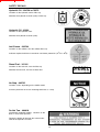
SAFETY MESSAGES
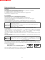
NOTE THE SAFETY ALERT SYMBOL (SHOWN BELOW). IT IDENTIFIES POTENTIAL
HAZARDS WHICH, IF NOT AVOIDED MAY RESULT IN INJURY OR DEATH! Also, observe
the safety messages places throughout this manual; providing special instructions, telling you when to take precautions
and to identify potential hazards. The safety messages are highlighted and outlined in a box similar to those shown in the
examples below.
SAFETY ALERT SYMBOL
NOTE or NOTICE
Provides information, special instructions or references about the lift truck.
IMPORTANT
Precautions which must be taken to avoid damage to the lift truck.
CAUTION
Indicates a potentially hazardous situation which, if not avoided, may result in minor or
moderate injury. May also alert unsafe practices.
WARNING
Indicates a potentially hazardous situation which, if not avoided, may result in death or
serious injury!
DANGER
Indicates an imminently hazardous situation which, if not avoided, will result in death or
serious injury.
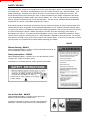
CALIFORNIA PROPOSITION 65 WARNING
Diesel Engine Exhaust and some of its constituents are known to the State of California
to cause cancer, birth defects or other reproductive harm.
WARNING: Battery posts, terminals and related accesories and related accessories
contain lead and lead compounds. Wash hands after handling.
IX
FORKLIFT SAFETY
CONTENTS
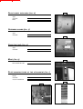
SAFETY DECALS
The purpose of this chapter is to introduce you to the safety messages, decals, and nameplates found on
your forklift truck. The decals are identified by name, part number, location, and a brief description. (The
forklift model logos, and other misc. decals not shown, can be found in your forklift parts manual.) The
decals illustrated may not be exactly the same as those installed on your forklift; installation of the decals
varies depending on the forklift model, series, decal updates, etc.. The size and location of some decals
limit the amount of information that can be placed upon it. For this reason, additional detailed information
not found on the decals is provided through-out this manual.
Every decal placed on the lift truck is important; they are constant reminders of safety and instructions that
should never be taken for granted. Even experienced operators can be seriously injured or killed by ignoring, refusing to enforce, or forgetting to follow safe operating procedures! Do not assume you know all safety issues concerning the decals. Before operating the lift truck; learn the meaning(s) of the decals as
described in this manual. If any decal becomes illegible or missing, have it replaced immediately! Always
replace decals using the same decal part no., unless otherwise specified by the manufacturer. For replacement decals not found in your parts manual, contact your nearest dealer. If you have any questions, contact
your supervisor or nearest dealer for advice before operating your forklift!
801011
Before Starting - 801011
(Boom equipped models). Location: on the brake fluid cover panel (to
the left and below the dash panel).
Safety Instructions - 420792
(Mast equipped models). Location: on or near the operator manual
storage case, and/or on the dash panel.
Instructions for the forklift operator; before operating the forklift.
Use of Seat Belt - 801012
(Boom equipped models). Location: to the right of the
operator, near the hydraulic control lever.
Instructs the operator to always wear the seat belt during
operations, and never jump from an over-turning forklift.
X
FORKLIFT SAFETY
CONTENTS
SAFETY DECALS
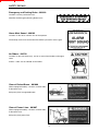
Emergency and Parking Brake - 801010
Location: near the park brake lever.
Identifies the Emergency/Parking Brake Lever.
Alarm Must Sound - 496162
Location: on the dash, in direct view of the operator.
The backup alarm must sound when the forklift is placed in reverse gear.
No Riders - 420732
Location: on the cab entrance(s), and on or near wheel fenders and engine
cover.
Informs: riders are not allowed on the forklift.
Clear of Raised Boom - 801006
(Boom equipped models). Location: on both sides
of the boom nose.
Keep away from unsupported boom.
Clear of Power Lines - 801007
(Boom equipped models). Location: on both sides
of the boom nose.
Keep away from power lines.
XI
FORKLIFT SAFETY
CONTENTS
SAFETY DECALS
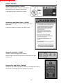
Use of Frame Leveling - 801013
(Boom equipped models). Location: to the right of
the operator near the hydraulic control lever.
Frame leveling notice; load must be lowered.
Attachment and Boom Safety - 801009
(Boom equipped models). Location: on both sides of the
boom nose.
Important reminders of attachment and boom safety.
Hydraulic Coupling - 234805
Location: near the quick-disconnect adapters.
Stop the engine and release hydraulic pressure before changing
attachments.
Rotating Fan and Belt(s) - 801008
Location: on the radiator near the fan, and on any fan belt/pulley cover(s).
Keep hands and clothing away from rotating fan and belts.
XII
FORKLIFT SAFETY
CONTENTS
SAFETY DECALS
Gear Shift Pattern - 33460
(4-speed transmission models). Location: near the gear shift lever.
Identifies the gear shift pattern of the forklift transmission.
Steering Mode - 184276
(4 wheel steer equipped models). Location: near the steering mode selection lever.
Identifies the steering mode selection.
221322
Mineral Oil (Brake Reservoir) - 221322 or 234800
Location: attached to the brake fluid reservoir.
Refer to the Operator/Service Manual for the correct brake fluid
(mineral oil) to be used in the brake system.
234800
XIII
FORKLIFT SAFETY
CONTENTS
SAFETY DECALS
Hydraulic Oil - 234798 or 76573
Location: on the hydraulic tank or filler cap.
Identifies the hydraulic reservoir (tank) or filler cap.
Hydraulic Oil - 61024
Location: on the hydraulic tank.
Identifies the hydraulic reservoir (tank).
Anti-Freeze - 234799
Location: on the radiator, near the radiator filler cap.
Indicates required minimum to maximum anti-freeze protection (-220F to -400F).
Diesel Fuel - 161101
Location: on the fuel tank, near the filler cap.
Identifies the fuel tank, and use of diesel fuel.
No Step - 496735
Location: varies, depending on the forklift model.
Instructs personnel not to use the designated area as a step.
Do Not Tow - 494918
(Hydrostatic equipped models). Location: on the
dash, in view of the operator.
Towing the forklift will damage the transmission;
refer to the operator’s manual.
XIV
FORKLIFT SAFETY
CONTENTS
SAFETY DECALS
Attachment Warning - 421016
(Boom equipped models). Location: on the boom coupler,
near where the retaining shaft is installed.
Reminder to operator; install attachment retaining shaft and
safety pin before operations.
Hook Here - 24653
Location: at points provided on the forklift, where straps or chains may be attached to
secure the forklift to a trailer during transport.
Fork Safety - 426641
(Mast equipped models). Location: on the front and back side of the mast’s outer rails,
at eye level (4 required).
Instructs personnel not to travel beneath or upon the lift truck forks.
Pinch Point, Large, 2.5 x 4.5 in. - 426643
Pinch Point, Small, 1.5 x 2.75 in. - 426642
(Mast equipped models). Location: on the front and rear sides
of the mast cross bracing.
Keep fingers away from the mast
crossbracing.
HAND THROTTLE DANGER - 804784
(Boom equipped models, option). Location: Near the hand throttle mechanism.
Reminder to operator; set parking brake before operating hand throttle.
Disengage hand throttle before leaving the forklift.
XV
FORKLIFT SAFETY
CONTENTS
SAFETY DECALS
Acid in Battery - 801014
Location: in or near the battery
storage compartment.
Addresses battery hazards.
Jump Start Battery - 801015
Location: in or near the battery storage
compartment.
Jump start instructions.
Attachment Plate - 425995
Location: on the optional removeable forklift attachment.
Important manufacturer information about the attachment. Record this information for use
when contacting the maufacturer for parts and service.
Overhead Guard Data Plate - B6109
Location: attached to the overhead guard.
Overhead guard conformity.
496550
Forklift Data Plate - 496550
(Boom equipped models)
Forklift Data Plate - 496538
(Mast equipped models)
Location: within the operator’s compartment.
Important forklift truck identification. Record
this information for use when contacting the
manufacturer for parts and service.
XVI
496538
FORKLIFT SAFETY
CONTENTS
TABLE OF CONTENTS
1 - OPERATING
AND SAFETY INSTRUCTIONS
– ORIGINAL REPLACEMENT PARTS AND ATTACHMENTS
– DRIVER'S OPERATING INSTRUCTIONS
• GENERAL INSTRUCTIONS
• OPERATING INSTRUCTIONS
• HANDLING INSTRUCTIONS
• LOAD HANDLING
– MAINTENANCE INSTRUCTIONS OF THE LIFT TRUCK
– BEFORE STARTING UP A NEW LIFT TRUCK
2 - DESCRIPTION
–
–
–
–
–
1-1
1-3
1-4
1-5
1-7
1 - 11
1 - 13
1 - 16
1 - 18
2-1
IDENTIFICATION OF THE LIFT TRUCK
CHARACTERISTICS
MAST CHARACTERISTICS
DIMENSIONS AND LOAD CHART
INSTRUMENTS AND CONTROLS (OVERHEAD GUARD MODEL)
3 - MAINTENANCE
2-4
2-6
2 - 12
2 - 14
2 - 16
3-1
– FILTERS CARTRIDGES AND BELTS
– LUBRICANTS AND FUEL
– SERVICING SCHEDULE
3-3
3-4
3-6
XV
FORKLIFT SAFETY
CONTENTS
FORKLIFT SAFETY
CONTENTS
1 - OPERATING
AND SAFETY
INSTRUCTIONS
1-1
FORKLIFT SAFETY
CONTENTS
1-2
FORKLIFT SAFETY
CONTENTS
ORIGINAL REPLACEMENT PARTS AND ATTACHMENTS
ALL MAINTENANCE ON OUR LIFT TRUCKS MUST BE CARRIED OUT USING ORIGINAL PARTS.
BY ALLOWING NON-ORIGINAL PARTS TO BE USED,
YOU RUN THE RISK
- Legally, of being liable in the event of an accident.
- Technically, of causing breakdowns to occur or of reducing your lift truck's service life.
IMPORTANT
Using counterfeit parts or components not approved by the manufacturer may put an end to
contract warranty terms and lead the maker to withdraw the lift truck's certificate of compliance.
BY USING ORIGINAL PARTS DURING MAINTENANCE OPERATIONS,
YOU ARE LEGALLY
COVERING
YOURSELF
- Any user who procures parts from another vendor does so at his own risk.
- Any user who modifies his lift truck or has it modified by a service company, must consider
that a new item of equipment has been brought onto the market and therefore takes liability
for it.
- Any user who copies original parts or has them copied is taking a risk from the legal viewpoint.
- The certificate of compliance only binds the maker for parts chosen or produced under the
maker's control.
- The practicalities of maintenance terms are set out by the maker. The maker is in no way
liable in the event of the user not complying with such terms.
YOU GET THE
BENEFIT OF THE
MANUFACTURER'S
KNOW-HOW
THE MANUFACTURER BRINGS TO THE USER,
- His know-how and skill.
- Guaranteed quality work.
- Original replacement parts.
- Help with preventive maintenance.
- Effective help with diagnosing faults.
- Enhancements gained from feedback.
- Training for operating staff.
- The manufacturer knows the details of the lift truck design and therefore has the best
technological capability to carry out maintenance.
1-3
FORKLIFT SAFETY
CONTENTS
DRIVER'S OPERATING INSTRUCTIONS
WARNING
WHENEVER YOU SEE THIS SYMBOL IN MEANS:
WARNING ! BE CAREFUL ! YOUR SAFETY OR THE SAFETY OF THE LIFT TRUCK IS AT RISK.
- Most accidents connected with the use, maintenance and repair of the lift truck are due to non application of the basic
safety instructions. By being aware of the risks to which you are exposed and by taking the necessary preventive
measures, you can avoid accidents.
- Any operation or maneuver not described in the instructions is prohibited, however, any person who does use another
method must first ensure that he is not putting himself, another person or the lift truck in danger.
- The manufacturer is not able to anticipate all possible risk situations. Therefore the safety instructions and notices
given in the user manual and on the lift truck are not conclusive.
Any bending of the rules in safety notices or the user, maintenance or repair instructions for your lift truck may result in
serious, or even fatal accidents.
We would remind users of the risks in driving at excessive speed with regard to traffic conditions, particularly:
- Risk of loss of control on a poor-quality track.
- Increased stopping distance.
The user must remain in full control of his lift truck and should:
- Adapt his speed to each situation in order to maintain his own safety, that of others and of his
equipment.
- Always be aware of his stopping distance.
On the basis of experience, there are a number of possible situations in which operating the lift truck is prohibited.
Such foreseeable abnormal uses, the main ones being listed below, are strictly forbidden.
- The foreseeable abnormal behavior resulting from ordinary neglect, but does not result from any wish to put the
machinery to any improper use.
- The reflex reactions of a person in the event of a malfunction, incident, fault, etc. during operation of the lift truck.
- Behavior resulting from application of the "principle of least action" when performing a task.
- For certain machines, the foreseeable behavior of such persons as: apprentices, teenagers, handicapped persons
and trainees tempted to drive a lift truck. Truck drivers tempted to operate a truck to win a bet, in competition or for
their own personal experience.
The person in charge of the equipment must take these criteria into account when assessing whether or not a person
will make a suitable driver.
1-4
FORKLIFT SAFETY
CONTENTS
GENERAL
INSTRUCTIONS
A - DRIVER’S OPERATING INSTRUCTIONS
- Read the operator's manual carefully, making sure you understand it.
- The operator’s manual must always be kept in the lift truck, in the place provided and in the language understood by
the operator.
- Every operation or maneuver not described in the manual must be assumed to be prohibited.
- Respect the safety notices and instructions given on the lift truck.
- It is mandatory to replace all plates or decals which are no longer legible or which have become worn or damaged.
B - AUTHORIZATION TO OPERATE
(Refer to the legislation for each particular country)
- Only qualified personnel may use the lift truck. Its use is subject to authorization to operate being given by the
appropriate manager in the user establishment.
- The user should always carry this authorization to operate with him while he is using the lift truck.
- The driver is not competent to authorize the driving of the lift truck by another person.
- In addition, the vehicle should be used in accordance with good practice for the profession.
C - MAINTENANCE
- The user must immediately advise his superior if his lift truck is not in good working order or does not comply with the
safety notice.
- The operator is prohibited from carrying out any repairs or adjustments himself, unless he has been trained for this
purpose. He must keep the lift truck properly cleaned if this is among his responsibilities.
- Carry out daily maintenance (See A - DAILY OR EVERY 10 HOURS SERVICE in SECTION 3 - MAINTENANCE).
- Ensure tires are adapted to the nature of the ground.
. SAND tires.
. LAND tires.
. Snow chains.
There are optional solutions, consult your agent or dealer.
WARNING
IMPORTANT
A worn or damaged tire can result in the lift truck being temporarily out of service.
The fitting of foam inflated tires is prohibited and is not guaranteed by the manufacturer, without
prior authorization.
- For your safety and that of others, making any modification to the structure or adjustment of the following components
on your lift truck is prohibited.
. Hydraulic pressure.
. Setting of limiting devices.
. Engine speed.
. Adding additional equipment.
If this occurs, the manufacturer will be released from any liability.
- To enable the vehicle to be maintained in a state of conformity, we advise you to have your lift truck checked regularly
by your agent or dealer. This should be done at least once every 6 months.
1-5
FORKLIFT SAFETY
CONTENTS
D - ENVIRONMENT
- A lift truck operating in an area without fire extinguishing equipment must be equipped with an individual extinguisher.
There are optional solutions, consult your agent or dealer.
- Take into account climatic and atmospheric conditions of the site of utilization.
. Protection against frost (See LUBRICANTS AND FUEL in SECTION 3 - MAINTENANCE).
. Adaptation of lubricants (Ask your dealer for information).
. Engine filtration.
. Lighting (Working headlight).
Optional solutions exist, consult your dealer.
WARNING
Use of a lift truck is prohibited in protected areas (i.e. refinery, explosive atmosphere). For use in
these areas, specific equipment is available as an option. Consult your dealer.
1-6
FORKLIFT SAFETY
CONTENTS
OPERATING
INSTRUCTIONS
A - DRIVER’S OPERATING INSTRUCTIONS
- Wear clothes suited for driving the lift truck, avoid loose clothes.
- Never operate the vehicle when hands or feet are wet or soiled with greasy substances.
- For increased comfort, adjust the driver’s seat to your requirements and adopt the correct position in the driver’s cab.
- The operator must always be in his normal position in the driver’s seat. It is prohibited to have arms or legs, or any part
of the body, protruding from the driver’s cab of the lift truck.
- Always remember to fasten your seat belt and adjust it to your requirements.
- The control levers must never in any event be used for any other than their intended purposes (i.e. climbing onto or
down from the lift truck, etc.).
- Never allow a passenger to travel on the lift truck or in the driver’s cab.
B - BEFORE STARTING THE LIFT TRUCK
- If the lift truck is new, refer to: BEFORE STARTING UP A NEW LIFT TRUCK in SECTION 1 - OPERATING AND
SAFETY INSTRUCTIONS.
- Check the condition of the tires and the tire pressures (See CHARACTERISTICS in SECTION 2 - DESCRIPTION).
- Before starting the lift truck, check the different levels:
. Engine oil.
. Hydraulic reservoir oil.
. Hydrostatic transmission oil.
. Cooling liquid.
- Also check for possible leakage of oil, fuel or liquid from the lift truck.
- Check the closing and locking of the hood.
- Whatever his experience as a truck driver, the operator is advised to familiarize himself with the position and operation
of all the controls and instruments before operating the lift truck.
C - STARTING THE LIFT TRUCK
SAFETY NOTICE
WARNING
The lift truck must only be started up or maneuvered when the operator is sitting in the driver’s
cab, with his seat belt adjusted and fastened.
- Never try to start the lift truck by pushing or towing it.
IMPORTANT
Such operation may cause severe damage to the transmission. If necessary, to tow the lift truck in
an emergency, the transmission must be placed in the neutral position (See
H - OCCASIONAL MAINTENANCE in SECTION 3 - MAINTENANCE).
INSTRUCTIONS
- Make sure that the forward/reverse lever is in neutral.
- Turn the ignition key to the position I to activate the electrical system.
- Check the level on the fuel level gauge.
- Turn the ignition key to position II to preheat for 15 seconds.
IMPORTANT
Do not engage the starter motor for more than 15 seconds and apply preheating for 10 seconds
between unsuccessful attempts.
1-7
FORKLIFT SAFETY
CONTENTS
- Press the accelerator pedal and turn the ignition key fully: the engine should then start. Release the ignition key and let
the engine run at idle.
- Check all control instruments immediately after starting up, when the engine is warm, and at regular intervals during
use, so as to quickly detect any faults and to be able to correct them without any delay.
- If an instrument does not show the correct display, stop the engine and immediately make the necessary repairs.
D - DRIVING THE LIFT TRUCK
SAFETY NOTICE
- Always drive the lift truck with the forks or attachment at approximately 300 mm (12 in) from the ground, i.e. in the
transport position.
- Familiarize yourself with the lift truck on the terrain where it will be used.
- Ensure that the service brakes and the sound alarm(s) are working properly.
- Drive according to, and at an appropriate speed for, the conditions and state of the terrain.
- Slow down before executing a turn.
- In all circumstances make sure you are in control of your speed.
- On damp, slippery or uneven terrain, drive slowly.
- Brake gently, never abruptly.
- Only use the lift truck’s forward/reverse lever from a stationary position and never do so abruptly.
- Do not drive with your foot on the brake pedal or with the parking brake on.
- Always remember that hydrostatic type steering is extremely sensitive to movement of the steering wheel, so turn it
gently and not abruptly.
- Do not allow the I.C. engine to idle needlessly for a long period.
- Never leave the engine on when the lift truck is unattended.
- Look in the direction of travel and always ensure you have good visibility of the route ahead.
- When working at night, ensure that your lift truck is fitted with full beam lights. There are optional solutions, consult your
agent or dealer.
- Drive around obstacles.
- Never move onto a loading platform without having first checked :
. That it is suitably positioned and secured.
. That the unit to which it is connected (tractor trailer, etc.) will not shift.
. That this platform is prescribed for the total weight of the lift truck to be loaded.
. That this platform is prescribed for the width of the lift truck.
- Never move onto a foot bridge, floor or freight lift, without being certain that they are prescribed for the weight and size
of the lift truck to be loaded and without having checked that they are in sound working order.
WARNING
Take extreme care with loading platforms, trenches, scaffolding, recently dug and/or backfilled
ground.
- The loaded lift truck must not travel at speeds in excess of 12 km/h (7.5 mph).
INSTRUCTIONS
- Raise the forks or attachment to the travel position approximately 300 mm (12 in) from the ground.
- Shift the forward/reverse lever to the selected direction of travel.
- Release the parking brake and accelerate gradually until the lift truck moves off.
1-8
FORKLIFT SAFETY
CONTENTS
E - STOPPING THE LIFT TRUCK
SAFETY NOTICE
- Before stopping the lift truck after a long working period, let the I.C. engine idle for a few moments, to allow the coolant
liquid and oil to lower the temperature of the engine and transmission.
IMPORTANT
Do not forget this precaution: frequently stopping the engine will raise the temperature of some
components, with the risk of badly damaging them.
- Never leave the ignition key in the lift truck when the lift truck is unattended.
- When the lift truck is stationary, place the forks or attachment on the ground, apply the parking brake, and put the
forward/reverse lever in neutral.
- If the driver has to leave the cab, even for a moment, it is essential to apply the parking brake and put the
forward/reverse lever in neutral.
- Make sure that the lift truck is not parked in any position that will interfere with the traffic flow and at less than 6 ft from
the track of a railway.
- In the event of prolonged parking on a site: protect the lift truck from bad weather, particularly from frost (check the
level of antifreeze), close the rear windows, lock the cab doors, and ensure that the hood is properly secured.
INSTRUCTIONS
- Park the lift truck on flat ground or on an incline less than 15 %.
- Release the accelerator pedal and stop the lift truck.
- Place the forward/reverse lever in neutral.
- Apply the parking brake.
- Lower the forks or attachment to rest on the ground.
- Stop the engine with the ignition switch.
- Remove the pressure in the hydraulic circuits by using the hydraulic controls.
- Remove the ignition key.
- Check the closing and locking of doors, windows and hood.
WARNING
Before leaving your driver's cab, ensure that you have carried out all operations for parking the
lift truck, for your safety and the safety of others.
F - DRIVING THE LIFT TRUCK ON THE PUBLIC HIGHWAY
SAFETY INSTRUCTIONS
- When driving a lift truck on roads open to public traffic, observe the provisions of the Highway Code.
- Lift truck drivers, driving on the public highway, must abide by the general provisions relative to highway traffic.
- The lift truck must conform to the provisions of the Highway Code. If necessary, optional solutions exist, consult your
dealer.
CAUTION
Transport of loads on the public highway is forbidden and attachments mounted on the lift truck
must be fitted with equipment in accordance with regulations or removed.
1-9
FORKLIFT SAFETY
CONTENTS
INSTRUCTIONS
- Ensure that the flashing light is in position and that it is working.
- Check the good working order and cleanness of lights, indicators and windscreen wiper.
- Check the adjustment of the rear view mirrors.
- Ensure that the fuel level is sufficient.
- Place the attachment at 300 mm (12 in) from the ground.
G - OPERATING THE LIFT TRUCK WITH A TRAILER
- For using a trailer, consult the regulations in force in your country (Maximum travel speed, braking, maximum weight of
trailer, etc.).
- Do not forget to connect the lift truck’s electrical equipment to that of the trailer.
- Do not use a non-braked trailer if the unit weight of a load exceeds that imposed by the highway code.
- Do not use a non-braked trailer without braking equipment for the trailer on the lift truck.
- Do not forget to connect the lift truck’s braking equipment to that of the trailer.
- The maximum vertical pull on the trailer hook must not exceed 1500 daN (3372 lbs).
- The authorized total towed weight (A.T.T.W.) must not exceed the maximum weight authorized by the manufacturer
(Consult the manufacturer’s plate on your lift truck).
IF NECESSARY, CONSULT YOUR DEALER.
1 - 10
FORKLIFT SAFETY
CONTENTS
HANDLING
INSTRUCTIONS
A - GENERAL
- Ensure the correct functioning of your lift truck’s attachments.
- Do not attempt to carry out operations which exceed the capacities of your lift truck or attachments.
- It is prohibited to increase the counterweight value in any way.
- It is prohibited to transport or carry persons in the lift truck, unless it is equipped to do so.
- Avoid traveling for a long distance in reverse.
B - ATTACHMENTS
- Ensure that the attachment is correctly fitted and locked to its frame.
- Conform to the limits on the load chart for the lift truck and/or attachment.
- Ensure that pallets, cases, etc, are in good order and suitable for the load to be lifted.
- Position the forks perpendicular to the load to be lifted, taking account of the load’s center of gravity.
- Never lift a load with a single fork.
- Never lift a sling load with a single fork or with the carriage. Optional solutions exist, consult your dealer.
- Ensure that the quick-fit or rapid hydraulic connections on the attachment system are clean and protected.
IMPORTANT
Before each change of an attachment with hydraulic function, in order to avoid damaging the
rapid hydraulic connections :
- Place the attachment in the closed position, flat on the ground (For unstable attachments,
ensure they are secured using wedges).
- Switch off the I.C. engine.
- Remove pressure from the attachment hydraulic system using the hydraulic controls.
C - ENVIRONMENT
- Signaling and lighting on the lift truck must take account of the conditions of use. In addition to series equipment
mounted on your lift truck, a certain number of options are available, such as: road lighting, stop lights, flashing light,
reverse lights, reverse buzzer alarm, front light, rear light, etc. Consult your agent or dealer.
- Take care when raising the load that no object or person is in the way of movement and do not make any incorrect
maneuvers.
- In the case of work near power lines, ensure that the safety distance is sufficient between the working area of the lift
truck and the power line.
WARNING
You must consult your local electrical agency. You could be electrocuted or seriously injured if you
operate or park the lift truck too close to power cables. You are strongly advised to ensure that the
safety rules on the site conform to the local regulations in force regarding all types of work carried
out close to power cables.
- Do not allow anybody to come near the working area of the lift truck or pass beneath an elevated load.
- When operating on a slope, before raising the mast, ensure that the terrain is as horizontal as possible. However, lift
trucks fitted with level correction may work on a steeper incline provided that the greatest part of the slope is corrected.
Travelling on a longitudinal slope :
• Drive and brake gently.
• Moving without load : Forks or attachment facing downhill.
• Moving with load : Forks or attachment facing uphill.
- Ensure that scaffolding, loading platform or pile is capable of bearing the weight.
- Ensure the stability and solidity of the ground before depositing a load.
1 - 11
FORKLIFT SAFETY
CONTENTS
D - HANDLING
- Always consider safety; only transport balanced and correctly secured loads to avoid any risk of tipping.
- Fully engage forks under the load and transport it in the low position (Approximately 12 in. from the ground), the mast
tilting backwards.
- For obvious reasons regarding the lift truck’s stability and clear visibility of the surrounding environment, only move the
lift truck when the mast is in the travel position (Approximately 12 in. from the ground).
- Do not maneuver the lift truck with the mast in the raised position unless under exceptional circumstances and then
with extreme caution, at very low speed, and using gentle braking. Ensure that visibility is adequate and get another
person to guide you along if necessary.
- Never shift the position of the load while the lift truck is in motion.
- The simultaneous use of two lift trucks to handle heavy or bulky loads is a dangerous maneuver, requiring specific
precautions to be taken. This should only be done in exceptional circumstances and in the presence of a handling
manager.
- Never drive too fast or brake abruptly when carrying a load.
- Check the load, particularly when turning corners and especially if it is very bulky.
- Secure unstable loads.
- Handle loads with caution, at slow speed, without sudden jerks when moving them at significant heights and mast
extention.
WARNING
In the event of high winds or storms, do not carry out handling work that jeopardizes the stability of
the lift truck and its load, particularly if the load catches the wind badly.
- Do not change direction sharply and at high speed.
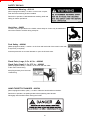
DANGER
In the event of the lift truck overturning, do not try to leave the cab during the incident.
YOUR BEST PROTECTION IS TO STAY FASTENED IN THE CAB.
- Apply the parking brake when lifting or depositing a difficult load or when on an incline.
- Do not park the lift truck with the load in an elevated position.
- Do not leave a laden lift truck with the parking brake applied on an incline which exceeds 15 %.
E - VISIBILITY
- If the visibility in forward motion is not sufficient because of the bulkiness of the load, drive in reverse motion. This
maneuver must remain exceptional and for short distances.
- Ensure you have good visibility (Clean windows, adequate lighting, correctly adjusted rear view mirror, etc.).
IF NECESSARY, CONSULT YOUR DEALER.
1 - 12
FORKLIFT SAFETY
LOAD
CONTENTS
HANDLING
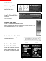
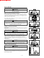
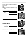
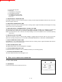
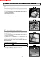
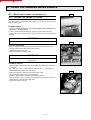
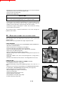
CAUTION
A
Carrying a load greater than the rated capacity for the lift truck or for the
attachment is prohibited.
24 in.
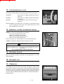
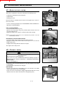
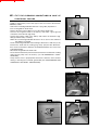
WEIGHT OF LOAD AND CENTER OF GRAVITY
- Before taking up a load, you must know its weight and its center of gravity.
- The load chart relating to your lift truck is valid for a weight with its center of
gravity 24 in. from the heel of the forks (Fig. A). For a higher center of
gravity, consult your agent or dealer.
B
- For irregular loads, determine the center of gravity in the transverse
direction before handling (Fig. B).
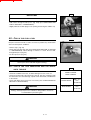
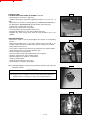
CAUTION
C
For loads with a moving center of gravity (i.e. liquids), take account of the
variations in the center of gravity in order to determine the load to be
handled (Consult your agent or dealer). Be vigilant and take extra care to
limit these variations as far as possible.
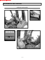
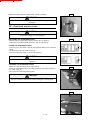
TAKING UP A LOAD ON THE GROUND
- Position the lift truck perpendicular to the load, with the forks in a horizontal
position (Fig. C).
- Adjust the fork spread and centering in connection with the load (Fig. D)
(Optional solutions exist, consult your dealer).
D
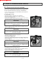
WARNING
Beware of the risks of trapping or injuring limbs when manually adjusting the
forks. Always maintain an equal distance between the forks and the center
of the carriage in order to keep the load completely stable.
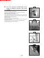
- Move the lift truck forward slowly (1), maneuvering the forks under the load
(Fig. E), if necessary, slightly lift the mast (2) while approaching the load.
- Apply the parking brake and place the forward/reverse lever in neutral.
- Slightly lift the load (1), incline the mast (2) backwards in the transport
position (Fig. F).
CAUTION
E
1
2
F
2
1
Tilt the load sufficiently backwards to ensure its stability (loss of load on
braking) without upsetting the balance of the load in so doing.
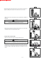
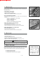
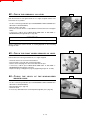
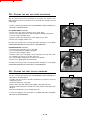
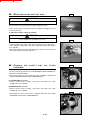
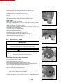
TAKING UP A HIGH LOAD ON TIRES
G
WARNING
Under no circumstances should you pick up a load if the lift truck is not in a
horizontal position. (See HORIZONTAL POSITION OF THE LIFT TRUCK).
- Ensure that the forks will easily pass under the load.
- Position the lift truck perpendicular to the load and with the forks in a
horizontal position (Fig. G).
1 - 13
FORKLIFT SAFETY
CONTENTS
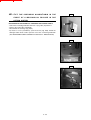
H
Maneuvering gently and carefully, place the forks under the load (Fig. H).
Apply the parking brake and place the forward/reverse lever in neutral.
- Slightly lift the load (1) and incline the mast (2) backwards to stabilize the
load (Fig. I).
I
2
CAUTION
Tilt the load sufficiently backwards to ensure its stability (loss of load on
braking) without upsetting the balance of the load.
1
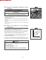
- Maneuvering very gently and carefully, back the lift truck (1) to clear the pile,
and bring the load into the transport position (Fig. J).
J
1
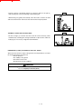
LAYING A HIGH LOAD ON TIRES
- Approach the pile with the load in the transport position (Fig. K).
K
WARNING
Under no circumstances should you lay down a load if the lift truck is not a
horizontal position. (See: HORIZONTAL POSITION OF THE LIFT TRUCK).
- Lift the mast (1) until the load is above the pile, and move the lift truck
forward (2) (Fig. L) maneuvering very gently and carefully. When the load is
in position, apply the parking brake and place the forward/reverse lever in
neutral.
L
1
2
1 - 14
FORKLIFT SAFETY
CONTENTS
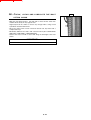
- Place the load in a horizontal position (1) and lay it down on the pile (2)
while checking the correct positioning of the load (Fig. M).
M
1
- Maneuvering very gently and carefully, lower the forks to release the load
and reverse the lift truck. Then lower the forks into the transport position.
2
3
TAKING UP A NON PALLETISED LOAD
N
- Tilt the carriage (1) forwards and move the lift truck forward (2) while
simultaneously crowding the carriage backwards to slip the forks under the
load (Fig. N). If necessary, wedge the load with blocks.
1
2
3
HORIZONTAL (LEVEL) POSITION OF THE LIFT TRUCK
Apart from the transverse slope of the ground, several parameters can upset
the horizontal position of the lift truck.
• The tire pressure.
• The stability of the ground.
• The balance of the load.
• Strong wind or stormy conditions.
WARNING
Before handling any work, check the points above and ensure that the lift
truck is completely horizontal (level).
1 - 15
FORKLIFT SAFETY
CONTENTS
MAINTENANCE INSTRUCTIONS OF THE LIFT TRUCK
MAINTENANCE
INSTRUCTIONS
A - GENERAL
- Read the operator's manual carefully and ensure you understand it.
- Stop the I.C. engine, when an intervention is necessary.
- Wear clothes suitable for the maintenance of the lift truck, avoid wearing jewellery and loose clothes. Tie and protect
your hair, if necessary.
- Ensure the area is sufficiently ventilated before starting the lift truck
IMPORTANT
Make sure that the disposal of process materials and spare parts is carried out in a safe and
ecological manner.
- Carry out all repairs immediately, even if the repairs concerned are minor.
- Repair all leaks immediately.
- Do not attempt to loosen unions, hoses or any hydraulic component with the circuit under pressure.
WARNING
The handling and removal of the balancing valves which may be fitted to the cylinders of your lift
truck can be dangerous. A balancing valve must be removed only after the cylinder is at rest and
the hydraulic circuit is depressurised.
This operation must be performed by authorized service personnel only!
- Do not smoke or approach the lift truck with a flame, when the fuel tank is open or is being filled.
- Take care not to burn yourself (Exhaust, radiator, I.C. engine, etc.).
- Disconnect the negative cable terminal (-) from the top of the battery before working on the electrical circuit or on the lift
truck (i.e., Welding).
- Do not drop metallic items on the battery.
- When welding on the lift truck, connect the negative cable from the equipment directly to the part being welded, so as
to avoid high tension current passing through the alternator.
B - MAINTENANCE
- The maintenance and compliance of the lift truck are mandatory.
- Carry out daily maintenance (See A - DAILY OR EVERY 10 HOURS SERVICE in SECTION 3 - MAINTENANCE).
- Do not run the engine without the air filter, or with oil, water or fuel leaks.
WARNING
Wait for the I. C. engine to cool before removing the radiator cap.
- Change the filter cartridges (See FILTERS CARTRIDGES AND BELTS in SECTION 3 - MAINTENANCE).
C - LEVELS
- Use the recommended lubricants (Never use contaminated lubricants).
- Do not fill the fuel tank when the I.C. engine is running.
- Fill the fuel tank only in areas specified for this purpose.
- Do not fill the fuel tank to the maximum level.
1 - 16
FORKLIFT SAFETY
CONTENTS
D - WASHING
- Clean the lift truck or at least the area concerned before servicing.
- Remember to close the doors and the windows of the cab.
- During washing, avoid the articulations, electrical components and connections.
IMPORTANT
Protect components susceptible of being damaged; from penetration of water, steam or cleaning
agents; particularly electrical components, connections, and the injection pump.
- Clean the lift truck of any fuel, oil or grease residue.
FOR ANY INTERVENTION OTHER THAN REGULAR MAINTENANCE, CONSULT YOUR DEALER.
1 - 17
FORKLIFT SAFETY
CONTENTS
BEFORE STARTING UP A NEW LIFT TRUCK
INTRODUCTION
- Our lift trucks have been designed for easy handling by the operator and maximum ease of maintenance for the
mechanic.
- However, before operating the lift truck, the user should carefully read and understand the various sections of this
manual which have been provided to solve driving and maintenance problems. By following these instructions the user
will be able to take full advantage of the versatility of this lift truck.
- The operator must familiarize himself with the positions and functions of all controls and instruments before operating
the lift truck.
IMPORTANT
Do not attempt to start a new lift truck before the following checks have been carried out:
LUBRICATION
- Check that all the correct grades of oils and greases that are required are available; see SERVICING SCHEDULE in
SECTION 3 - MAINTENANCE and top up if necessary.
IMPORTANT
For operation under average climatic conditions, i.e. between -15 °C and + 35 °C (5° to 95°F), correct
levels of lubricants in all the circuits are checked in production. For operation under more severe
climatic conditions, before starting up, it is necessary to drain all the circuits, then add the correct
levels of lubricants properly suited to the relevant ambient temperatures. It is the same for the
cooling liquid (Contact your dealer for information, if necessary).
DRY AIR FILTER
- Ensure that the air filter is undamaged and not blocked.
- Tighten the fastening devices if necessary.
IMPORTANT
Never run the engine with the air filter removed or damaged.
COOLING SYSTEM
- Do not start the lift truck without checking the radiator coolant level or if the fan belt is damaged or broken.
HYDRAULIC SYSTEM
- Check for leaks from the hoses, connections, and components. If necessary, tighten or repair the defective
connections.
- Also check that the tank oil level is correct.
TIRES
- Make sure that the wheel nuts are correctly tightened (See A - DAILY OR EVERY 10 HOURS SERVICE in
SECTION 3 - MAINTENANCE) and that the tire pressures are correct (See CHARACTERISTICS in SECTION 2 DESCRIPTION).
FUEL SYSTEM
- Check that all fuel lines are secured.
- If necessary drain the fuel filter and bleed the fuel system of air.
ELECTRICAL CIRCUIT
- Check the level and the density of the electrolyte in the battery (See B - EVERY 50 HOURS SERVICE in SECTION 3 MAINTENANCE).
- Check the components of the electrical system, the connections and fastening devices.
IF NECESSARY, CONSULT YOUR DEALER.
1 - 18
FORKLIFT SAFETY
CONTENTS
2 - DESCRIPTION
2-1
FORKLIFT SAFETY
CONTENTS
2-2
FORKLIFT SAFETY
CONTENTS
2-3
FORKLIFT SAFETY
CONTENTS
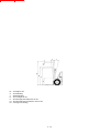
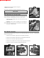
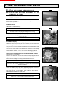
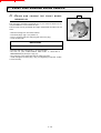
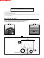
IDENTIFICATION OF THE LIFT TRUCK
As our policy is to promote a constant improvement of our products, our
range of telescopic lift trucks may undergo certain modifications, without prior
notice to our customers.
When you order parts, or when you require any technical information, always
specify:
A
NOTE: For the owner's convenience, it is recommended that a note of these
numbers is made in the spaces provided, at the time of the delivery of
the lift truck.
PLATE
MANUFACTURER OF THE LIFT TRUCK ( FIG . A )
- Model
- Series
- Serial No.
- Chassis No.
- Year of manufacture
I.C.
B
ENGINE ( FIG . B )
- Engine No.
HYDROSTATIC
C
PUMP ( FIG . C )
- Pump No.
- Codification type
- Manufacturer’s No.
- Year of manufacture
D
HYDROSTATIC
WHEEL ENGINES ( FIG . D )
- Manitou part number
- Codification type
- Engine No.
- Manufacturer’s No.
- Year of manufacture
2-4
FORKLIFT SAFETY
CONTENTS
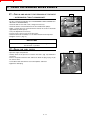
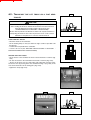
FRONT
WHEEL REDUCERS ( FIG . E )
E
- Type
- Serial No.
- Date
OVERHEAD
GUARD ( FIG . F )
- Type
- Serial No.
F
CABIN (OPTION) (FIG. G)
- Type
- Serial No.
MAST (FIG. H)
G
- Mast identification No.
PLATE
MANUFACTURER OF THE ATTACHMENT ( FIG . I )
- Model
- Serial No.
- Year of manufacture
I
H
2-5
FORKLIFT SAFETY
CONTENTS
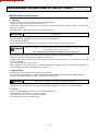
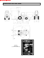
CHARACTERISTICS
ENGINE
UP TO MACHINE N° 139125
- Type
- Number of cylinders
- Number of strokes
- Injection system
- Ignition sequence
- Rocker arm clearance (Hot)
. Inlet
. Exhaust
- Capacity
- Bore
- Stroke
- Volumetric ratio
- Nominal running speed (Without soundproofing)
- Nominal running speed (With soundproofing)
- Idle speed
- Full speed
- Power DIN 70.020
- Power DIN 6270 B
- Power SAE
- Power BS.AU 141 a 1971
- Maximum torque
- Air cleaner
PERKINS 903-27
3
4
Direct
1.2.3.
0,20 mm (.008 in)
0,45 mm (.018 in)
2700 cm3 (164.7 cu in)
95 mm (3.74 in)
127 mm (5 in)
17.5 : 1
2250 rpm
2100 rpm
850 rpm
2400 rpm
52,3 cv
38,5 kw
51 cv
37,5 kw
51,5 cv
37,9 kw
54,3 cv
40 kw
190 Nm à 1200 tr/mn (140 ft/lb)
Sec 3 microns
ENGINE
FROM MACHINE N° 139126
- Type
- Number of cylinders
- Number of strokes
- Injection system
- Ignition sequence
- Rocker arm clearance (Hot)
. Inlet
. Exhaust
- Capacity
- Bore
- Stroke
- Volumetric ratio
- Nominal running speed
- Idle speed
- Full speed
- Power ISO 3046-1
- Power ISO/TR 14396
- Power SAE
- Maximum torque ISO 3046-1
- Maximum torque ISO/TR 14396
- Air cleaner
PERKINS 903-27 LOW EMISSION
3
4
Direct
1.2.3.
0,20 mm (.008 in)
0,45 mm (.018 in)
2700 cm3 (1063 cu in)
95 mm (3.74 in)
127 mm (5 in)
17.5 : 1
2100 rpm
850 rpm
2400 rpm
50 cv
37 kw
52 cv
38,5 kw
54 cv
40 kw
190 Nm à 1200 tr/mn (140 ft/lb)
192 Nm à 1200 tr/mn (142 ft/lb)
Sec 3 microns
2-6
FORKLIFT SAFETY
CONTENTS
COOLING
CIRCUIT
- Type
- Fan
By water
Sucking (up to machine n° 130839)
Blowing (from machine n° 130840)
6
406,4 mm (16 in)
. Number of blades
. Diameter
- Thermostat
. Start opening
. Full opening
ELECTRIC
80/84 °C (176-183.2°F)
96 °C (204.8°F)
CIRCUIT
- Earth
- Battery
- Alternator
- Tension regulator
- Starter
HYDROSTATIC
Negative
12 V - 105 Ah - 680 A EN
14 V - 55 A
Incorporated into the alternator.
12 V - 2,2 kw
TRANSMISSION
HYDROSTATIC PUMP
- Type
A4VG90DA With variable cubic capacity and
with automatic power governor.
Electromagnetic 12V.
- Gear reverser
- Main pump
. MAX. displacement
. MINI. displacement
. MAX. flow rate
. Working pressure
- Boost pump
. Cubic capacity
. MAX. flow rate
. Boost pressure MAX. r.p.m.
90 cm3 (35.43 cu in)
0 cm3
215 L/mn (56.8 gal/mn)
500 Bar (7250 psi)
18,7 cm3 (7.36 cu in)
42 L/mn (11.1 gal/mn)
30 Bar (Transmission in neutral).
(435 psi)
HYDROSTATIC WHEEL ENGINE (MOTOR)
- Type
. Cubic capacity
FRONT
A2FE With fixed capacity.
28 cm3 (11.02 cu in)
WHEEL REDUCERS
- Type
CWD 2050/M BREVINI
BRAKE
- Type
- Number of steel disks
- Number of friction disks
- Service brakes
Multidisc brake immersed in oil.
4
4
Foot pedal. Hydraulic brake acting on front
wheels through pressure break.
Switch. Electro-hydraulic brake acting on front
wheels through pressure break.
- Parking brakes
2-7
FORKLIFT SAFETY
CONTENTS
MSI 30 D BUGGIE
FRONT
TIRES
STANDARD
DIMENSIONS
PRESSURE
275/70 R22,5 G391
GOOD YEAR (Industrial)
9 Bar
130 psi
OPTION
DIMENSIONS
PRESSURE
10,5 R20 14PR MPT80 134G
CONTINENTAL (Mixed)
5,6 Bar
81 psi
8-25-20 CSE SC10
CONTINENTAL (Solid)
285/70 R19,5 XZY 140/137L
MICHELIN (Industrial)
8 Bar
116 psi
275/70 R22,5 G391
GOOD YEAR (Industrial wide-base)
9 Bar
130 psi
IMPORTANT
10,5 R20 14PR MPT80 134G
CONTINENTAL (Wide-base mixed)
5,6 Bar
81 psi
15,5/55 R18 SPPG7 14PR
DUNLOP (Wide-base mixed)
4,5 Bar
65 psi
When changing or replacing the tires and wheels; use
only the manufacturer’s approved components as
installed at the factory. Any substitutes or
modifications must first be approved by the
manufacturer.
15,5/55 R18 SPPG7 14PR
DUNLOP (Extra wide-base mixed)
4,5 Bar
65 psi
12.0x18 12PR T86
DUNLOP (Mixed)
4,2 Bar
61 psi
REAR
TIRES
STANDARD
DIMENSIONS
PRESSURE
700x12 14PR IC40
CONTINENTAL (Industrial)
6,7 Bar
97 psi
OPTION
DIMENSIONS
PRESSURE
27.10.12 12PR IC12
CONTINENTAL (Industrial or mixed)
4,5 Bar
65 psi
7.00-12 CSE SC10
CONTINENTAL (Solid)
700R12 136 A5 XZM
MICHELIN (Industrial)
4,75 Bar
69 psi
2-8
FORKLIFT SAFETY
CONTENTS
HYDRAULIC
CIRCUIT
UP TO MACHINE N° 127568
Gear pump
- Type of pump
. Capacity
- Lifting, tilting, attachment circuit
. Flow rate at full speed
. Pressure
- Steering direction
. Flow rate at full speed
. Pressure
- Filtration
. Return
. Suction
HYDRAULIC
33 cm3 (13 cu in)
80 L/mn. (21.13 gal/mn)
185 Bar (2,682.5 psi)
Load control system
125 Bar (1,812.5 psi)
20 Microns
100 Microns
CIRCUIT
FROM MACHINE N° 127569
Gear pump with flow divider
32,6 cm3 (12.83 cu in)
- Type of pump
. Capacity
- Lifting, tilting, attachment circuit
. Flow rate at full speed
. Pressure
- Steering direction
. Flow rate at full speed
. Pressure
- Filtration
. Return
. Suction
73 L/mn (19.28 gal/mn)
185 Bar (2,682.5 psi)
73 L/mn (19.28 gal/mn)
125 Bar (1,812.5 psi)
20 Microns
100 Microns
SPECIFICATIONS
UP TO MACHINE N° 127568
- Level of sound pressure in the driver's cabin
(According to norm prEN 12053 : 1995)
. Overhead guard model
. Cabin model
dBA
79 dBA
- Travel speed of the lift truck
. Forward unladen
. Reverse unladen
21 km/h (13 mph)
21 km/h (13 mph)
- Standard lift height
3300 mm (Mât DUPLEX) (129.92 in)
- Rated capacity with standard mast
3000 kg (6,613.8 lb)
610 mm (24 in)
- Load center
55 kg (121.25 lb)
- Weight of forks (Each)
- Lifting movement (With standard mast)
. Unladen lifting
. Rated load lifting
. Unladen lowering
. Rated load lowering
0,54 m/s (1.77 ft/sec)
0,48 m/s (1.57 ft/sec)
0,46 m/s (1.5 ft/sec)
0,49 m/s (1.6 ft/sec)
2-9
FORKLIFT SAFETY
CONTENTS
- Weight of lift truck with standard mast
. Unladen
. Rated load
- Weight per axle with standard mast (Transport position)
. Front unladen
rated load
. Rear unladen
rated load
4515 kg (9,953 lb)
7515 kg (16,567 lb)
1795 kg (3,957 lb)
6710 kg (14,793 lb)
2720 kg (5,996 lb)
805 kg (1,774 lb)
- Drawbar pull
. Unladen
. Rated load
1300 daN (2,922 lb)
2500 daN (5,620 lb)
- Maximum ramp negotiable in forward motion
. Unladen
. Rated load
27 % à 1 km/h (.6 mph)
34 % à 1 km/h (.6 mph)
- Break out force with bucket
(According to standard ISO 8313)
daN
SPECIFICATIONS
FROM MACHINE N° 127569
- Level of sound pressure in the driver's cabin
(According to norm prEN 12053 : 1995)
. Overhead guard model
. Cabin model
dBA
79 dBA
- Travel speed of the lift truck
. Forward unladen
. Reverse unladen
19,5 km/h (12 mph)
19,5 km/h (12 mph)
- Standard lift height
3300 mm (DUPLEX mast) (129.9 in)
- Rated capacity with standard mast
2721 kg (6,000 lb)
610 mm (24 in)
- Load center
55 kg (121 lb)
- Weight of forks (Each)
- Lifting movement (With standard mast)
. Unladen lifting
. Rated load lifting
. Unladen lowering
. Rated load lowering
0,49 m/s (1.7 ft/sec)
0,44 m/s (1.4 ft/sec)
0,46 m/s (1.5 ft/sec)
0,49 m/s (1.7 ft/sec)
- Weight of lift truck with standard mast
. Unladen
. Rated load
- Weight per axle with standard mast (Transport position)
. Front unladen
rated load
. Rear unladen
rated load
4515 kg (9,954 lb)
7515 kg (16,567 lb)
1795 kg (3,957 lb)
6710 kg (14,793 lb)
2720 kg (5,996 lb)
805 kg (1,774 lb)
- Drawbar pull
. Unladen
. Rated load
1300 daN (2,922 lb)
2500 daN (5,620 lb)
2 - 10
FORKLIFT SAFETY
CONTENTS
- Maximum ramp negotiable in forward motion
. Unladen
. Rated load
27 % à 1 km/h (.6 mph)
34 % à 1 km/h (.6 mph)
- Break out force with bucket
(According to standard ISO 8313)
daN
2 - 11
FORKLIFT SAFETY
CONTENTS
MAST CHARACTERISTICS
DOUBLE MAST WITH ALL-ROUND VISION - mm (in)
MSI 30 D
MAST
3m00
(9.9 ft)
3m30
(10.9 ft)
3m50
(11.6 ft)
3m70
(12.2 ft)
4m00
(13.2 ft)
4m50
(14.6 ft)
5m00
(16.5 ft)
5m50
(18.1 ft)
HL
3035
(119.4)
3335
(131.3)
3535
(139.2)
3735
(147)
4035
(158.9)
4535
(178.5)
5035
(198.2)
5535
(217.9)
Z
10°
Y
12°
10°
12°
10°
12°
10°
12°
10°
12°
10°
12°
6°
6°
6°
6°
LL
H
H1
135
2155 3895
(5.3) (84.8) (153.3)
135
2305 4195
(5.3) (90.7) (165.1)
135
2405 4395
(5.3) (94.7) (173)
135
2565 4595
(5.3) (101) (181)
135
2755 4895
(5.3) (108.5) (192.7)
135
3005 5395
(5.3) (118.3) (212.4)
135
3255 5895
(5.3) (128.1) (232.1)
135
3505 6395
(5.3) (138) (251.7)
H2
290
(11.4)
290
(11.4)
290
(11.4)
230
(9.1)
190
(7.5)
190
(7.5)
190
(7.5)
190
(7.5)
DOUBLE MAST WITH TOTAL FREE-ACTING LIFT - mm (in)
MSI 30 D
MAST
3m00
(10 ft)
3m30
(10.9 ft)
3m50
(11.6 ft)
3m70
(12.3 ft)
4m00
(13.3 ft)
HL
3045
(119.8)
3345
(131.7)
3545
(139.6)
3745
(147.4)
4045
(159.3)
Z
10°
Y
12°
10°
12°
10°
12°
10°
12°
10°
12°
LL
1400
(55.1)
1550
(61)
1650
(65)
1810
(71.3)
2000
(78.7)
H
H1
2155 3800
(84.8) (149.6)
2305 4100
(90.7) (161.4)
2405 4300
(94.7) (169.3)
2565 4500
(101) (177.2)
2755 4800
(108.5) (189)
H2
154
(6.1)
154
(6.1)
154
(6.1)
154
(6.1)
154
(6.1)
TRIPLE MAST WITH TOTAL FREE-ACTING LIFT - mm (in)
MSI 30 D
MAST
3m70
(12.3 ft)
4m00
(13.3 ft)
4m30
(14.3 ft)
4m70
(15.6 ft)
5m00
(16.6 ft)
5m50
(18.2 ft)
6m00
(19.8 ft)
6m50
(21.5 ft)
7m00
(23.1 ft)
HL
3745
(147.4)
4045
(159.3)
4345
(171.1)
4745
(186.8)
5045
(198.6)
5545
(218.3)
6045
(238)
6545
(257.7)
7045
(277.4)
Z
10°
Y
12°
10°
12°
10°
12°
10°
12°
6°
6°
6°
6°
6°
6°
6°
6°
6°
6°
LL
H
H1
1300 2055 4500
(51.2) (80.9) (177.2)
1400 2155 4800
(55.1) (84.8) (189)
1550 2305 5100
(61) (90.7) (200.1)
1650 2405 5500
(65)
(95) (216.5)
1810 2565 5800
(71.3) (101) (228.3)
2000 2755 6300
(78.7) (108.5) (248)
2250 3005 6800
(88.6) (118.3) (267.7)
2500 3255 7300
(98.4) (128.1) (287.4)
2750 3505 7800
(108.3) (138) (307)
H2
34
(1.3)
34
(1.3)
34
(1.3)
34
(1.3)
34
(1.3)
34
(1.3)
34
(1.3)
34
(1.3)
34
(1.3)
2 - 12
FORKLIFT SAFETY
CONTENTS
TRIPLE MAST WITHOUT FREE-ACTING LIFT
MSI 20 D + BUGGIE
MAST
HL
Z
Y
LL
H
H1
H2
3m30*
3340
10°
12°
0
1830
4070
40
* Tyres 10,5 - 20 8 PR MPT 123 G AS FARMER CONTINENTAL
TRIPLE MAST WITHOUT FREE-ACTING LIFT
MSI 25 D + BUGGIE
MAST
HL
Z
Y
LL
H
H1
H2
3m30*
3340
10°
12°
0
1830
4070
40
3m30**
3340
10°
12°
0
1845
4070
25
* Tyres 275/80 R 20 XM 27 MICHELIN
** Tyres 275/70 R 22,5 G391 GOOD YEAR
HL
Z
Y
LL
H
H1
H2
: Lift height in mm
: Forward tilting
: Backward tilting
: Free-acting lift in mm
: Overall height with folded mast in mm
: Overall height with spreaded out mast in mm
: Carriage overshooting
2 - 13
FORKLIFT SAFETY
CONTENTS
DIMENSIONS AND LOAD CHART
MSI 30 D
LOAD CHART
(Located on the dashboard)
2 - 14
FORKLIFT SAFETY
CONTENTS
MSI 30 D
A
1100 mm (43.30 in)
B
1800 mm (70.86 in)
C
630 mm (24.80 in)
D
2980 mm (117.32 in)
E
4080 mm (160.63 in)
F
1046 mm (41.18 in)
F1
1102 mm (43.38 in)
G
275 mm (10.83 in)
G*
245 mm (9.65 in)
G1
260 mm (10.24 in)
G1*
260 mm (10.24 in)
G2
215 mm (8.46 in)
G2*
230 mm (9.06 in)
G3
270 mm (10.63 in)
H
2305 mm (90.75 in)
H*
2055 mm (80.91 in)
H1
4205 mm (165.55 in)
H1*
4500 mm (177.17 in)
I
550 mm (21.65 in)
J
1025 mm (40.35 in)
K
1260 mm (49.61 in)
L
45 mm (1.77 in)
N
1450 mm (57.09 in)
O
100 mm (3.94 in)
P1
49,5 °
P2
40,5 °
P3
40 °
R
2300 mm (90.55 in)
S
2525 mm (99.41 in)
T
4525 mm (178.15 in)
U-U*
2105 mm (82.87 in)
V
2595 mm (102.16 in)
V1
100 mm (3.94 in)
W
1323 mm (52.09 in)
Y
12 °
Z
10 °
H - H1
H* - H1*
G - G1 - G2
G* - G1* - G2*
= Standard mast DUPLEX 3M30
= Option mast TRIPLEX 3M70
= Unladen
= Rated load
2 - 15
FORKLIFT SAFETY
CONTENTS
INSTRUMENTS AND CONTROLS
OVERHEAD GUARD MODEL
10
1
6
3
8
4
14
7
2
9
5
14
18
13
1
17
7
5
9
16
2
11
12
15
2 - 16
FORKLIFT SAFETY
CONTENTS
DESCRIPTION
1 - DRIVER’S SEAT
2 - SAFETY BELT
3 - SIGNAL LAMP PANEL
4 - FUEL LEVEL GAUGE AND HOURMETER
5 - SWITCH PANEL
6 - HORN SWITCH
7 - IGNITION SWITCH
8 - KEY-OPERATED BATTERY DISCONNECTING DEVICE
9 - FUSE BOX
10 - WINDSCREEN WASHER TANK
11 - ACCELERATOR PEDAL
12 - PEDAL OF TRANSMISSION CUT-OFF AND OF SERVICE BRAKES
13 - FORWARD/REVERSE LEVER
14 - HYDRAULIC CONTROL DISTRIBUTOR LEVERS
15 - DOCUMENT HOLDER
16 - DOCUMENT CLIP
17 - TOWING PIN
18 - OVERHEAD GUARD LIFTING
NOTE: All terms such as: RIGHT, LEFT, FRONT, REAR are meant for an observer as seated normally in the driver's
seat, facing straight ahead.
2 - 17
FORKLIFT SAFETY
CONTENTS
1 - DRIVER’S
SEAT
FOR OPTIMAL COMFORT, THIS SEAT CAN BE ADJUSTED IN
DIFFERENT WAYS.
2
E
D
LONGITUDINAL ADJUSTMENT
- Pull the locking lever 1 upwards.
- Slide the seat to the required position.
- Release the lever and ensure it returns to the lock position.
C
B
A
1
SEAT SUSPENSION ADJUSTMENT
- Pull and lift up the locking lever 2 so as to place it into one of these five
positions.
Position A : Light-weight driver 110 lb (50 kg).
Position B : Intermediate.
Position C : Middle-weight driver.
Position D : Intermediate.
Position E : Heavy-weight driver 265 lb (120 kg).
3
ANGLE ADJUSTMENT OF THE BACK-REST
- Pull the locking lever 3 backwards.
- Tilt the back-rest into one of the three possible positions.
- Release the locking lever and ensure it returns to the lock position.
ANGLE ADJUSTMENT OF THE WHOLE SEAT
- Lift up the locking lever 4.
- Tilt the seat forwards or backwards.
- Release the lever and ensure it returns to the lock position.
2 - SAFETY
4
BELT
FROM MACHINE N° 134 092
- Sit correctly on the seat.
- Check that seat belt is not twisted.
- Place the seat belt at hip level and not across the stomach.
- Attach the seat belt and check that it locks.
- Adjust the seat belt to your body shape without squeezing your hip.
WARNING
In no event should the lift truck be used if the seat belt is defective (any
physical damage, cuts, tears, etc.). Replace the seat belt immediately.
3 - SIGNAL
LAMP PANEL
When activating the electrical system of the lift truck, all the lamps and the
panel's buzzer must light to indicate their good working order. If one of the
lamps or the buzzer does not function, carry out the necessary repairs.
A B C D E
A - Red engine oil pressure lamp.
B - Red water temperature lamp.
C - Red hydrostatic transmission oil filter clog lamp.
F G H
2 - 18
I
J
FORKLIFT SAFETY
CONTENTS
D - Red air filter clog lamp.
E - Not used.
F - Red alternator charge lamp.
G - Red parking brake lamp.
H - OPTION Green indicator lamp.
I - OPTION Blue main beam lamp.
J - Not used.
A - RED ENGINE OIL PRESSURE LAMP
If the lamp or the buzzer come on while the lift truck is running, stop the engine immediately and look for the cause (See
oil level in engine crankcase).
B - RED WATER TEMPERATURE LAMP
If the lamp or the buzzer come on while the lift truck is running, stop the engine immediately and investigate the cooling
system for the cause of the malfunction.
C - RED HYDROSTATIC TRANSMISSION OIL FILTER CLOG LAMP
This lamp informs the operator about the good working condition of the filter cartridge. If it is clogged, the red lamp and
the buzzer light up (For replacement see FILTERS CARTRIDGES AND BELTS in SECTION 3 - MAINTENANCE).
NOTE: Let the lift truck run after a cold start, the lamp should go out once the hydraulic oil has reached its operating
temperature.
D - RED AIR FILTER CLOG LAMP
The lamp or the buzzer come on when the filter cartridge is clogged. Stop the lift truck and carry out the necessary
repairs (For cleaning and replacement see FILTERS CARTRIDGES AND BELTS in SECTION 3 - MAINTENANCE).
F - RED ALTERNATOR CHARGE LAMP
If the lamps B - C - D - F or the buzzer come on while the lift truck is running, stop the engine immediately and check the
electrical circuit as well as the alternator belt.
G - RED PARKING BRAKE LAMP
This lighted lamp indicates that the parking brake is engaged.
H - OPTION GREEN INDICATOR LAMP
It is illuminated when the indicators are on and indicates that they are functioning properly.
I - OPTION BLUE MAIN BEAM LAMP
The lamp is illuminated when main beam lights are on.
4 - FUEL
LEVEL GAUGE AND HOURMETER
A - FUEL LEVEL GAUGE
B
B - HOURMETER
It shows the number of hours the lift truck has run.
2 - 19
A
FORKLIFT SAFETY
CONTENTS
5 - SWITCH
1st ASSEMBLY
PANEL
1st and 2nd ASSEMBLY
A - Parking brake switch.
B - Front windscreen wiper switch and windscreen washer.
C - OPTION rear windscreen washer switch.
D - OPTION heater fan switch.
E - Overhead guard lifting switch.
F - OPTION warning light switch.
G - OPTION working head light switch.or
OPTION left working head light switch.
H - OPTION flashing alarm light switch.
I - OPTION working tail light switch.or
OPTION left working tail light switch.
A B C D E
F
G
H
I
2nd ASSEMBLY
2nd ASSEMBLY
J - OPTION Cold country heater fan switch.
K - OPTION.
A B C
F E
G H I
J K
NOTE: For the first assembly, the layout of the switches may be different
depending on the option(s) fitted on the lift truck.
A - PARKING BRAKE SWITCH
To engage the parking brake, press the bottom of the switch. The signal lamp
shows it is being used. To disengage the parking brake, press the top of the
switch.
B - FRONT WINDSCREEN WIPER SWITCH AND WINDSCREEN
WASHER
This two position switch, when set in the "down" position and simultaneously
pressed, allows the windscreen-washer and the windscreen wiper to be operated,
and when set in the "up" position, the windscreen wiper operates.
D
1st ASSEMBLY
1
E - OVERHEAD GUARD LIFTING SWITCH
See 18 OVERHEAD GUARD LIFTING for operation of the switch.
2nd ASSEMBLY
1
6- HORN
SWITCH
7 - IGNITION
SWITCH
The key switch has five positions :
P - Ignition off, parking position.
O - Ignition switched off and engine stopped.
I - Ignition on.
II - Heating.
III - The engine starts, return to position I as soon as the key is released.
8 - KEY-OPERATED
BATTERY DISCONNECTING DEVICE
Enables instant cut-off of the battery from the electric circuit in the event of a short circuit or a fire.
2 - 20
FORKLIFT SAFETY
CONTENTS
9 - FUSE
BOX
Remove the cover to gain access to the fuses.
13
14
22
15
16
17
23
1 - OPTION Light switch, horn and indicators (15A).
7
8
9
10
2 - OPTION Warning lights (10A).
3 - OPTION Rear windscreen wiper (7,5A).
19
20
4 - OPTION Working tail lights (10A).
1
2
3
4
OPTION Left working tail light (10A).
5 - OPTION Working head lights (10A).
OPTION Left working head light (10A).
6 - OPTION Heating (15A).
7 - Panel of signal lights + Fuel level gauge + Hourmeter (5A).
8 - Front windscreen wiper and windscreen washer (10A).
9 - OPTION Flashing light unit (10A).
10 - Gear reverser + OPTION Reverse lights + OPTION Reverse gear horn (10A).
11 - Sound alarm + Parking brake + Transmission cut-off + OPTION Stop switch (10A).
12 - OPTION Flashing alarm light (7,5A).
13 - OPTION Right sidelights + OPTION Fuel level gauge lighting + OPTION Hourmeter lighting (5A).
14 - OPTION Left sidelights (5A).
15 - OPTION Right indicators (7,5A).
16 - OPTION Left indicators (7,5A).
17 - OPTION Dipped headlight (10A).
18 - OPTION Main beams + OPTION main beam lamp (10A).
19 - OPTION Roof light (3A).
20 - OPTION.
21 - OPTION.
22 - OPTION.
23 - OPTION.
24 - Overhead guard lifting (5A).
18
24
11
12
21
5
6
NOTE: Replace a worn fuse with a new fuse of equal quality and capacity. Do not re-use a repaired fuse.
10 - WINDSCREEN
WASHER TANK
11 - ACCELERATOR
12 - PEDAL -
PEDAL
TRANSMISSION CUT- OFF AND SERVICE BRAKES
This pedal operates in two steps :
- First, the pedal acts upon an electric switch which puts the transmission into neutral so as to slow down the lift truck.
- Then, the pedal acts upon a hydraulic valve which progressively gives rise to a pressure drop in the brakes so as to
stop the lift truck.
NOTE: A hydraulic transmission cut-off OPTION is available to allow the transmission to be cut progressively.
2 - 21
FORKLIFT SAFETY
CONTENTS
13 - FORWARD/REVERSE
LEVER
The lift truck must be stationary when operating the forward / reverse lever.
A
FORWARD
From Position C: Lift slightly and push the lever up to
Position A.
From Position C: Lift slightly and push the lever down
to Position B.
To start the truck, the lever must be in neutral
(Position C).
REVERSE
NEUTRAL
C
B
NOTE: OPTIONAL reverse lights exist, these lights are automatically turned
on when shifting into reverse gear. The backup alarm must sound
when engaging the reverse gear.
14 - HYDRAULIC
CONTROL DISTRIBUTOR LEVERS
LEVER A : Controls the load lifting and the mast tilting.
- Move lever backward to raise the forks.
- Move lever forward to lower the forks.
- Move lever to the right to tilt mast forward.
- Move lever to the left to tilt mast back.
NOTE: The engine r.p.m. automatically increases when lifting the load.
LEVER B : Designed for additional (optional) equipment control.
WARNING
Do not attempt to alter the hydraulic system pressure by interfering with the
pressure regulating valve. In the event of suspected malfunction, contact
your dealer.
ANY ALTERATION MAY VOID THE WARRANTY.
15 - DOCUMENT
HOLDER
Make sure that the operator’s manual is in the right place, i.e. in the
document holder.
16 - DOCUMENT
17 - TOWING
CLIP
PIN
Located at the back of the truck, this pin makes it possible to couple a trailer.
The capacity is limited for each lift truck by the Permissible Total Moveable
Weight (P. T. M. W.), the drawbar pull and the maximum vertical drawbar pull
on the towing pin. This information is indicated on the manufacturer's plate on
each lift truck (See IDENTIFICATION OF THE LIFT TRUCK in SECTION 2 DESCRIPTION).
2 - 22
A
B
FORKLIFT SAFETY
CONTENTS
NOTE: For towing, optional solutions exist, consult your dealer.
A
WARNING
Before towing trailers, ensure that the safety clip is fully engaged in the
towing pin.
B
1
18 - OVERHEAD
GUARD LIFTING
A
CAUTION
Make sure that the mast is tilted forwards to a maximum and the engine is
stopped before lifting the overhead guard.
UNLOCKING THE OVERHEAD GUARD
- With the engine stopped, place the key switch in the “on” position.
- Unlock the overhead guard with the lever 1 (Fig. A) in position A.
LIFTING THE OVERHEAD GUARD
- Press the top of the switch 2 (Fig. B) until complete lifting of the overhead
guard.
- Put the lever 1 back into position B (Fig. A).
- Place the safety prop 3 (Fig. C) into its stop 4 (Fig. C).
B
1st ASSEMBLY
2
2nd ASSEMBLY
CAUTION
2
Check for any objects left in the operator’s area which may interrupt the lifting
operation.
LOWERING THE OVERHEAD GUARD
- Return the safety prop back into its clip 5 (Fig. D).
- Lower the overhead guard into its initial position by pressing the bottom of
the switch 2 (Fig. B).
- Ensure that the overhead guard is locked.
C
3
CAUTION
Check for clearance and obstacles while lowering the overhead guard.
4
D
5
2 - 23
FORKLIFT SAFETY
CONTENTS
2 - 24
FORKLIFT SAFETY
CONTENTS
3 - MAINTENANCE
3-1
FORKLIFT SAFETY
CONTENTS
3-2
FORKLIFT SAFETY
CONTENTS
FILTERS CARTRIDGES AND BELTS
1
2
3
4
5
11
6
7
8
10
9
12
DESIGNATION
PART NUMBER
CLEAN
CHANGE
1 - Engine oil filter
211 384
2 - Dry air filter cartridge (*)
177 129
3 - Safety dry air filter cartridge (*)
177 178
4 - Dry air filter cartridge (**)
227 959
5 - Safety dry air filter cartridge (**)
227 960
800 H
6 - Hydrostatic transmission oil filter cartridge
46 028
800 H
7 - Hydraulic return oil filter cartridge
+ Oil tank breather
217 031
400H
8 - Fuel filter cartridge
49 660
400 H
9 - Fan belt
561 299
10 - Suction strainer for hydraulic oil tank
77 402
11 - Automatic vacuum-cleaning pre-filter (OPTION)
160 945
12 - Air pre-filter (OPTION)
23410 F2030 71
(*) Up to machine N° 139 125
(**) machine N° 139 126
3-3
400 H
50 H
400 H
800 H
50 H
800 H
400 H
FORKLIFT SAFETY
CONTENTS
LUBRICANTS AND FUEL
COMPONENT
CAPACITY
RECOMMENDATION
I.C. ENGINE
5 L. (1.3 gal) Shell: Rotella 15w40
Texaco: URSA Super +15w40
FRONT WHEEL REDUCERS
1,1 L.(.29 gal) Shell: Spirax DH 80w90
Texaco: Multi-gear EP 80w90
HYDRAULIC OIL TANK
95 L.(25 gal) Shell: Tellus T46
Texaco: Rando HDZ46
MAST LIFTING CHAINS
Engine oil
GREASING WITH WIELAND RINGS
Shell: Rentinax Am
Texaco: Havoline WBCG
GENERAL GREASING
Shell: Rentinax Am
Texaco: Havoline WBCG
COOLING CIRCUIT
FUEL TANK
11 L.(2.9 gal) Texaco Texguard Anti-Freeze
45/55 Pre-mix (-220F)
73,5 L.
(19.4 gal) Diesel fuel Grade 1-D
DIAGNOSTIC ANALYSIS OF OIL
In the event of a maintenance or service contract with the dealer, you may be requested to provide a sample of a
selected component's oil, for diagnostic analysis.
3-4
FORKLIFT SAFETY
CONTENTS
3-5
FORKLIFT SAFETY
CONTENTS
SERVICING SCHEDULE
AFTER
D1
D2
D4
D5
D6
E3
F1
THE FIRST
WORKING HOURS SERVICE
- Drain and change the engine oil.
- Change the engine oil filter.
- Change the fuel filter cartridge.
- Change the hydraulic return oil filter cartridge.
- Change the oil tank breather.
- Change the hydrostatic transmission oil filter cartridge.
- Drain and change the front wheel reducer oil.
A - EVERY
A1
A2
A3
A4
50
DAY OR EVERY
10
3 - 18
3 - 18
3 - 19
3 - 19
3 - 19
3 - 22
3 - 28
WORKING HOURS SERVICE
- Check the engine oil level.
- Check the cooling liquid level.
- Check the fuel level.
- Check the tire pressure and the wheel nut torque.
B - EVERY 50
3 - 10
3 - 10
3 - 11
3 - 11
WORKING HOURS SERVICE
B1 - Clean the dry air filter cartridge.
(In heavily dust laden atmosphere, service more frequently).
B2 - Check the hydraulic oil level.
B3 - Check the front wheel reducer oil level.
B4 - Check the level of the windscreen washer liquid.
B5 - Check the battery electrolyte level.
B6 - Clean the radiator core.
B7 - Check and adjust the tension and alignment of the mast lifting chains.
B8 - Greasing with Wieland rings.
B9 - General Greasing.
C - EVERY 200
3 - 13
3 - 13
3 - 13
3 - 14
3 - 14
3 - 14
3 - 15
3 - 15
WORKING HOURS SERVICE
C1 - Check and adjust the tension of the belt Alternator / Fan / Crankshaft.
C2 - Drain the fuel filter.
D - EVERY 400
3 - 12
3 - 17
3 - 17
WORKING HOURS SERVICE
To be carried out once a year if the lift truck has not reached the 400 hours service in the year.
D1
D2
D3
D4
D5
D6
D7
D8
D9
- Drain and change the engine oil.
- Change the engine oil filter.
- Change the dry air filter cartridge.
- Change the fuel filter cartridge.
- Change the hydraulic return oil filter cartridge.
- Change the oil tank breather.
- Check the density of the battery electrolyte.
- Check, clean and lubricate the mast lifting chains.
- Check the wear of the forks (*).
3 - 18
3 - 18
3 - 19
3 - 19
3 - 20
3 - 20
3 - 20
3 - 21
(* Consult your dealer).
3-6
FORKLIFT SAFETY
CONTENTS
E - EVERY 800
WORKING HOURS SERVICE
To be carried out once a year if the lift truck has not reached the 800 hours service in the year.
3 - 22
3 - 22
3 - 22
3 - 23
3 - 25
3 - 25
E1 - Drain and change the hydraulic oil.
E2 - Clean the suction strainer of the hydraulic oil tank.
E3 - Change the hydrostatic transmission oil filter cartridge.
E4 - Drain and change the cooling liquid.
E5 - Drain and clean the fuel tank.
E6 - Change the safety dry air filter cartridge.
E7 - Check the brake circuit pressure (*).
E8 - Check the brake adjustment (*).
E9 - Check the engine silentblocs (*).
E10 - Check the engine speeds (*).
E11 - Check the attachment carriage (*).
E12 - Check the condition of the wheels and tires (*).
E13 - Check the speeds of the hydraulic movements (*).
E14 - Check the condition of the attachments (*).
E15 - Clean the hydraulic pump tubular filter (*).
E16 - Clean the brake solenoid valve filter (*).
E17 - Check the injectors (*).
E18 - Check and adjust the valves clearances (*).
(* Consult your dealer).
F - EVERY 2400
WORKING HOURS SERVICE
F1 - Drain and change the front wheel reducer oil.
(This operation should be carried out once a year if the lift truck has not reached 2400
hours service within the year).
F2 - Check the hydraulic circuit pressures and discharge rates (*).
F3 - Check the hydrostatic transmission circuit pressures (*).
F4 - Check and adjust the governing start r.p.m. of the hydrostatic transmission (*).
F5 - Check the chain roller wear (*).
F6 - Check the mast guide rolls (*).
F7 - Check the mast bearing rollers (*).
F8 - Check the mast lifting chains (*).
F9 - Check the thickness of the mast wearing plates (*).
F10 - Check the working order of the hydraulic valves for the transmission cut-off and accelerator (*).
F11 - Check the steering system (*).
F12 - Clean the hydraulic oil tank (*).
F13 - Check the oscillation of the rear axle (*).
F14 - Check and scale the radiator (*).
F15 - Check the water pump and the thermostat (*).
F16 - Check the condition of the mast assembly (*).
F17 - Check the alternator and the starter motor (*).
(* Consult your dealer).
G - EVERY 4800
WORKING HOURS SERVICE
G1 - Check the wear of the brake disks (*).
G2 - Check the steering axle (*).
(* Consult your dealer).
3-7
3 - 26
FORKLIFT SAFETY
CONTENTS
H - OCCASIONAL
H1
H2
H3
H4
H5
H6
H7
H8
MAINTENANCE
- Bleed the fuel system.
- Change a wheel.
- Tow the lift truck.
- Sling the lift truck.
- Transport the lift truck on a flat semitrailer.
- Lift the overhead guard or the cabin in case of electric failure.
- Lift the overhead guard or the cabin in the event of an hydraulic failure in the lifting system.
- Lift the overhead guard or the cabin in the event of a mechanical failure in the lifting system.
3-8
3 - 28
3 - 28
3 - 29
3 - 30
3 - 31
3 - 32
3 - 33
3 - 34
FORKLIFT SAFETY
CONTENTS
3-9
FORKLIFT SAFETY
CONTENTS
A - EVERY DAY OR EVERY 10 WORKING HOURS SERVICE
A1 - CHECK
THE ENGINE OIL LEVEL
A1/1
Park the truck on level ground with the engine stopped, and let the oil drain
into the sump.
- Lift the overhead guard/cabin (See INSTRUMENTS AND CONTROLS in
SECTION 2 - DESCRIPTION).
- Remove the dipstick 1 (Fig. A1/1).
- Clean the dipstick and check the level between the MAXI and MINI notches.
- If necessary, add oil (See LUBRICANTS AND FUEL in SECTION 3 MAINTENANCE) by the filler port 2 (Fig. A1/2).
1
A1/2
2
A2 - CHECK
THE COOLING LIQUID LEVEL
Park the lift truck on level ground with the I.C. engine stopped, and wait for
the engine to cool down.
A2/1
- Lift the overhead guard/cabin (See INSTRUMENTS AND CONTROLS in
SECTION 2 - DESCRIPTION).
- The liquid must be at the MAXIMUM level in the expansion tank 1 (Fig.
A2/1).
- If necessary, add cooling liquid through the filler port 2 (Fig. A2/1).
When the expansion tank is empty, check the level in the radiator before
filling the expansion tank.
2
1
- Disassemble the cover plate 3 (Fig. A2/2).
WARNING
ALWAYS ALLOW THE RADIATOR TO COOL
BEFORE OPENING THE RADIATOR CAP!
- Slowly rotate the radiator cap 4 (Fig. A2/3) to the safety stop.
- Allow any pressure to escape.
- Press down and turn the cap to release it.
3 - 10
A2/2
3
FORKLIFT SAFETY
CONTENTS
A2/3
IMPORTANT
DO NOT ADD COOLANT TO A HOT RADIATOR - ALLOW THE ENGINE TO COOL.
4
- Add coolant through the filler port 5 (Fig. A2/3) (See LUBRICANTS AND
FUEL in SECTION: 3 - MAINTENANCE).
- Slightly lubricate the filler plug to ease opening and closing the radiator cap.
5
A3 - CHECK
THE FUEL LEVEL
A3
Keep the fuel tank near full, to reduce as much as possible any condensation
due to the atmospheric conditions.
- Remove cap 1 (Fig. A3).
- Fill the fuel tank with clean fuel (See LUBRICANTS AND FUEL in SECTION
3 - MAINTENANCE), filtered through a strainer or a clean, lint free cloth,
through filler port 2 (Fig. A3).
- Put the cap back 1 (Fig. A3).
1
2
WARNING
Never smoke or approach with a flame during filling operations or when the
tank is open. Never refill while engine is running.
A4 - CHECK
THE TIRE PRESSURES AND THE WHEEL
A4
NUTS TORQUE
- Check the condition of the tires, to detect damage from cuts, wear, etc.
- Check the torque load of the wheel nuts (See fig. A4). Non compliance with
this instruction can cause damage, rupture of the wheel bolts, and distortion
to the wheels.
- Check and adjust the tire pressures if necessary (See CHARACTERISTICS
SECTION 2 - DESCRIPTION).
WARNING
Check that the air hose is correctly connected to the tire valve before
inflating, and keep all persons at a distance during inflation. Follow the
recommended tire pressures given.
3 - 11
WHEEL TORQUE
NUTS LOADING
FRONT WHEEL
400 ± 15%
N.m
250-340 ft lbs
REAR WHEEL
110 ± 15%
N.m
70-94 ft lbs
FORKLIFT SAFETY
CONTENTS
B - EVERY 50 WORKING HOURS SERVICE
B1 - CLEAN
THE DRY AIR FILTER CARTRIDGE
In case of use in a heavily dust laden atmosphere, inspect frequently and see
FILTERS CARTRIDGES AND BELTS in SECTION 3 - MAINTENANCE.
- Lift the overhead guard/cabin (See INSTRUMENTS AND CONTROLS in
SECTION 2 - DESCRIPTION).
UP TO MACHINE N° 139 125
- Unscrew nut 1 (Fig. B1/1), and remove cover 2 (Fig. B1/1).
- Unscrew nut 3 (Fig. B1/1), and lift out filter cartridge 4 (Fig. B1/1).
- Leave the safety cartridge in place.
- Clean the filter cartridge using a low pressure air jet (max. 40 psi) directed
only from the inside to the outside surface of the cartridge.
B1/1
2
3
IMPORTANT
Respect the safety distance of 1.5 in. between the air jet and the cartridge
to avoid tearing or making a hole in the cartridge. The cartridge must not be
blown anywhere near the air filter box. Never clean the cartridge by tapping
it against a hard surface.
1
4
- Clean the inside of the casing with a clean, damp, lint-free cloth.
- Check the condition of the filter cartridge, replace the cartridge if necessary.
- Refit the cartridge and the cover.
IMPORTANT
Do not clean the dry air filter cartridge by washing it in liquid. Do not clean
the safety cartridge located inside the filter cartridge, change it for a new
one if it is dirty or damaged.
FROM MACHINE N° 139 126
- Loosen the nuts and remove the cover 1 (Fig. B1/2).
- Release filter cartridge 2 (Fig. B1/2).
- Leave the safety cartridge in place.
- Clean the filter cartridge using a low pressure air jet (max. 40 psi) directed
only from the inside to the outside surface of the cartridge, at least 1.5 in.
from the cartridge wall.
- Cleaning is complete when there is no more dust on the cartridge.
IMPORTANT
Respect the safety distance of 1.5 in. between the air jet and the cartridge
to avoid tearing or making a hole in the cartridge. The cartridge must not be
blown anywhere near the air filter box. Never clean the cartridge by tapping
it against a hard surface.
- Clean the inside of the casing with a clean, damp, lint-free cloth. Also clean
the cartridge seal surfaces on the filter and cover.
- Check the condition of the filter cartridge, replace the cartridge if necessary.
- Insert the cartridge making sure it is in the correct position.
- Replace the cover, guiding the valve downwards.
IMPORTANT
Do not clean the dry air filter cartridge by washing it in liquid. Do not clean
the safety cartridge located inside the filter cartridge, change it for a new
one if it is dirty or damaged.
3 - 12
B1/2
1
2
FORKLIFT SAFETY
CONTENTS
B2 - CHECK
THE HYDRAULIC OIL LEVEL
Park the lift truck on level ground with the I.C. engine stopped and the mast
lowered as far as possible.
B2
1
2
- Lift the overhead guard/cabin (See INSTRUMENTS AND CONTROLS in
SECTION 2 - DESCRIPTION).
- Refer to gauge 1 (Fig. B2).
- The level is correct when it is equal distance between the lower and upper
marks.
- If necessary, add oil (See LUBRICANTS AND FUEL in SECTION 3 MAINTENANCE) through filler port 2 (Fig. B2).
IMPORTANT
Always use a clean funnel and nozzle when filling.
Always maintain the correct oil level, as cooling depends on the oil flowing
through the tank.
B3 - CHECK
B3
THE FRONT WHEEL REDUCER OIL LEVEL
Park the lift truck on level ground with the I.C. engine stopped.
- Check the oil level on each front wheel reducer.
- Place the plugs 1 (Fig. B3) into a horizontal position.
- Remove one of the plugs, the oil must be flush with the port.
- If necessary, add oil (See LUBRICANTS AND FUEL in SECTION 3 MAINTENANCE) through the same port.
- Replace the plug 1 and tighten it (Fig. B3) (Tightening torque 44 - 52 ft/lb)
B4 - C H E C K
THE LEVEL OF THE WINDSCREEN
1
1
B4
WASHER LIQUID
1
- Lift the overhead guard/cabin (See INSTRUMENTS AND CONTROLS in
SECTION 2 - DESCRIPTION).
- Open the filling cap 1 (Fig. B4).
- Check the level.
- If necessary, add windscreen washer liquid through filler port 2 (Fig. B4).
3 - 13
2
FORKLIFT SAFETY
CONTENTS
B5 - CHECK
THE BATTERY ELECTROLYTE LEVEL
Check the electrolyte level in each cell of the battery. If the truck is working in
a high temperature environment, check the level more frequently.
B5
1
1
1
1
- Lift the overhead guard/cabin (See INSTRUMENTS AND CONTROLS in
SECTION 2 - DESCRIPTION).
- Remove the caps 1 (Fig. B5) from each cell of the battery.
- The correct level is at 3/8 in. above the top of the plates in the battery.
- If necessary, top up the cells with clean distilled water.
- Clean and dry caps 1 (Fig. B5) and refit in place.
- Check the terminal connections, lightly smear them with petroleum jelly to
prevent corrosion.
WARNING
Handling and servicing a battery can be dangerous, take the following
precautions:
- Wear protective goggles.
- Keep the battery horizontal.
- Never smoke or work near an open flame.
- Work in a well-ventilated area.
- In the event of electrolyte being spilled onto the skin or splashed in the
eyes, rinse thoroughly with cold water for 15 minutes and call a doctor.
B6 - CLEAN
THE RADIATOR CORE
B6
- Lift the overhead guard/cabin (See INSTRUMENTS AND CONTROLS in
SECTION 2 - DESCRIPTION).
Clean the radiator with a compressed air jet directed from the front to the
back (Fig. B6). This is the best way to efficiently remove debris.
IMPORTANT
When handling straw, grains or cereals, clean the radiator core every day.
B7 - C H E C K
AND ADJUST THE TENSION AND
ALIGNMENT OF THE MAST LIFTING CHAINS
Park the lift truck on level ground with the mast in a vertical position and the
forks lifted at approximately 200 mm (8 in).
- Check the alignment of the mast lifting chains between the carriage’s chain
fasteners and the chain rollers.
- Manually verify the chain tension, if necessary adjust as following, while
ensuring that the carriage is perpendicular to the mast:
- Loosen the nut 1 (Fig. B7).
- Loosen the lock nut 2 (Fig. B7) of the chain tension adjuster.
- Adjust the tension by tightening or loosening the nut 3 (Fig. B7) while
checking the alignment of the lifting chains.
B7
1
3
2
3 - 14
1
1
FORKLIFT SAFETY
CONTENTS
- Tighten the lock nut 2 (Fig. B7) and the nut 3 (Fig. B7).
- Retighten the nut 1 (Fig. B7).
B8/1
These checks are important for the good working operation of the mast.
IMPORTANT
In case of technical problems, consult your dealer.
B8 - GREASING
1
WITH WIELAND RINGS
Clean and lubricate the following points with grease (See LUBRICANTS AND
FUEL in SECTION 3 - MAINTENANCE) and remove the surplus grease.
1 - Lubricators of the articulation axles at the foot of the mast 1 (Fig.
B8/1) (2 lubricators).
B8/2
2 - Lubricators of the foot axles 2 (Fig. B8/2) on the tilt cylinders (2
lubricators).
NOTE: Lift the overhead guard/cabin (See INSTRUMENTS AND CONTROLS
in SECTION 2 - DESCRIPTION).
2
B9 - GENERAL
GREASING
Clean and lubricate the following points with grease (See LUBRICANTS AND FUEL in SECTION 3 - MAINTENANCE).
Remove any surplus grease.
1 - Lubricators of the head axles 1 (Fig. B9/1) on the tilt cylinders (2 lubricators).
2 - Lubricators of the head axles 2 (Fig. B9/2) on the steering cylinder (2 lubricators).
3 - Lubricators of the swivel pins 3 (Fig. B9/3) (4 lubricators).
4 - Lubricators of the oscillation axle on the hind carriage 4 (Fig. B9/4) (2 lubricators).
5 - Lubricators of cabin door 5 (Fig. B9/5) (Cabin model) (4 lubricators).
B9/2
B9/1
B9/3
3
1
3
2
3 - 15
FORKLIFT SAFETY
CONTENTS
B9/4
B9/5
5
4
3 - 16
FORKLIFT SAFETY
CONTENTS
C - EVERY 200 WORKING HOURS SERVICE
C1 - CHECK AND ADJUST THE TENSION OF
- ALTERNATOR / FAN / CRANKSHAFT
THE BELT
C1
1
- Lift the overhead guard/cabin (See INSTRUMENTS AND CONTROLS in
SECTION 2 - DESCRIPTION).
- Check the belt for wear and cracks, change it if necessary.
- Check the tension of the belt between the fan and alternator pulleys.
- Under a normal pressure exerted with the thumb, the tension should be
approximately 10 mm (3/8 in).
- Carry out adjustments if necessary.
- Loosen screws 1 (Fig. C1) by two to three turns.
- Swivel the alternator assembly so as to obtain the belt tension required.
- Retighten screws 1 (Fig. C1).
1
1
IMPORTANT
If the alternator belt has to be changed, check the tension again after the
first 20 hours of operation.
C2 - DRAIN
THE FUEL FILTER
C2
- Open the engine compartment.
- Visually check for the presence of water in the tank 1 (Fig. C2) and drain if
necessary.
- Place a receptacle under the tank and loosen drain the plug 2 (Fig. C2) by
two of three turns.
- Let the diesel fuel flow until it is free from impurities and water.
- Tighten the drain plug.
3 - 17
1
2
FORKLIFT SAFETY
CONTENTS
D - EVERY 400 WORKING HOURS SERVICE
D1 - DRAIN AND CHANGE THE ENGINE
D2 - CHANGE THE ENGINE OIL FILTER
OIL
D1/1
Park the truck on level ground, let the engine run at idle for a few minutes,
then stop the engine.
DRAINING THE OIL
- Lift the overhead guard/cabin (See INSTRUMENTS AND CONTROLS in
SECTION 2 - DESCRIPTION).
- Place a container under drain plug 1 (Fig. D1/1) and unscrew the plug.
- Remove filler cap 2 (Fig. D1/2) in order to ensure that the oil is drained
properly.
1
IMPORTANT
Dispose of the drain oil in an ecological manner.
D1/2
REPLACE THE FILTER
- Remove engine oil filter 3 (Fig. D1/3); discard the filter and the filter seal.
- Clean the filter bracket with a clean, lint-free cloth.
- Lightly lubricate the new seal.
- Refit the oil filter on the filter bracket.
2
4
IMPORTANT
Tighten the oil filter by hand pressure only and lock the filter in place by a
quarter turn.
FILLING UP THE OIL
- Refit and tighten drain plug 1 (Fig. D1/1) (Tightening torque 30 to 40 N.m or
22 - 30 ft/lbs).
- Fill with oil (See LUBRICANTS AND FUEL in SECTION 3 MAINTENANCE) by filler port 4 (Fig. D1/2).
- Wait a few minutes to allow the oil to flow into the sump.
- Start the engine and let it run for a few minutes.
- Check for possible leaks at the drain plug and the oil filter.
- Stop the engine, wait a few minutes and check the level between the two
upper notches on the dipstick 5 (Fig. D1/3).
- Top up the level if necessary.
3 - 18
D1/3
5
3
FORKLIFT SAFETY
CONTENTS
D3 - CHANGE
THE DRY AIR FILTER CARTRIDGE
The air used to burn the fuel is purified by a dry air filter. It is therefore very
important that the lift truck should never be used with the cartridge removed
or damaged.
D3/1
- Lift the overhead guard/cabin (See INSTRUMENTS AND CONTROLS in
SECTION 2 - DESCRIPTION).
UP TO MACHINE N° 139 125
- Unscrew nut 1 (Fig. D3/1) and remove cover 2 (Fig. D3/1).
- Unscrew nut 3 (Fig. D3/1), lift out and discard filter cartridge 4 (Fig. D3/1).
- Leave the safety cartridge in place.
- Clean the inside of the casing with a clean, damp, lint free cloth.
- Refit the new cartridge and the cover.
2
3
1
4
If the lift truck is being used in a heavily dust laden atmosphere, see FILTERS
CARTRIDGES AND BELTS in SECTION 3 - MAINTENANCE.
FROM MACHINE N° 139 126
- Loosen the nuts and remove cover 1 (Fig. D3).
- Lift out and discard filter cartridge 2 (Fig. D3).
- Leave the safety cartridge in place.
- Clean the inside of the casing with a clean, damp, lint free cloth. Also clean
the cartridge seal surfaces on the filter and cover.
- Fit a new cartridge, making sure it is in the correct position.
- Refit the cover, guiding the valve downwards.
D3/2
1
2
If the lift truck is being used in a heavily dust laden atmosphere, see FILTERS
CARTRIDGES AND BELTS in SECTION 3 - MAINTENANCE.
D4 - CHANGE
THE FUEL FILTER CARTRIDGE
- Lift the overhead guard/cabin (See INSTRUMENTS AND CONTROLS in
SECTION 2 - DESCRIPTION).
- Carefully clean the exterior of the filter and bracket to prevent the dust from
entering the system.
- Unscrew locking screw 1 (Fig. D4).
- Remove tank 2 (Fig. D4) and discard cartridge 3 (Fig. D4) and seals.
- Clean the inside of the filter head and tank, using a brush immersed in clean
diesel oil.
- Refit the assembly with a new cartridge and seals.
- If necessary, bleed the fuel circuit (See H1 - BLEED THE FUEL SYSTEM in
SECTION 3 - MAINTENANCE).
3 - 19
D4
1
3
2
FORKLIFT SAFETY
CONTENTS
D5 - C HANGE
THE HYDRAULIC RETURN OIL FILTER
D5
CARTRIDGE
D6 - CHANGE
THE OIL TANK BREATHER
IMPORTANT
2
1
To prevent debris from entering the hydraulic circuit, thoroughly clean the
outside of the filter and its surroundings before servicing.
3
- Lift the overhead guard/cabin (See INSTRUMENTS AND CONTROLS in
SECTION 2 - DESCRIPTION).
- Unscrew the cover.
- Remove the hydraulic return oil filter cartridge 1 (Fig. D5) and replace it with
a new one.
- Disassemble the cover 2 (Fig. D5) and change the oil tank breather 3
(Fig. D5).
- Ensure that the cartridge and the breather are correctly positioned and
install the covers.
D7 - C H E C K
THE
DENSITY
OF
THE
B AT T E RY
ELECTROLYTE
D7
The electrolyte density varies depending on the temperature concerned, but a
minimum of 1260 at 16° C (61°F) must be maintained.
In the shaded area (Fig. D7), the battery is in a normal charge condition.
Readings above this zone indicate that the battery needs to be recharged.
The density should not vary more than 0.025 units between cells.
- Lift the overhead guard/cabin (See INSTRUMENTS AND CONTROLS in
SECTION 2 - DESCRIPTION).
- Check the electrolyte density in each battery cell using a hydrometer.
Do not perform this check immediately after adding distilled water. Recharge
the battery for at least an hour before checking the battery electrolyte density.
WARNING
Handling and servicing a battery can be dangerous, take the following
precautions:
- Wear protective goggles.
- Keep the battery horizontal.
- Never smoke or work near an open flame.
- Work in a well-ventilated area.
- In the event of electrolyte being spilled onto the skin or splashed in the
eyes, rinse thoroughly with cold water for 15 minutes and call a doctor.
3 - 20
1.240
1.250
1.260
1.270
1.280
1.290
1.300
°C -18 -10 0 10 20 30 40
°F 0 14 32 50 68 86 104
FORKLIFT SAFETY
CONTENTS
D8 - C H E C K ,
C L E A N A N D L U B R I C AT E T H E M A S T
D8
LIFTING CHAINS
- Wipe the mast lifting chains 1 (Fig. D8) with a clean, lint-free cloth, then
examine them closely for any signs of wear.
- Vigorously brush the chains to remove any foreign matter, using a hard
nylon brush and clean diesel fuel.
- Rinse the chains with a brush and clean diesel fuel; dry them with a
compressed air jet.
- Moderately lubricate the chains with a brush and oil (See LUBRICANTS
AND FUEL in SECTION 3 - MAINTENANCE).
- Remove the excess oil with a clean cloth along the full length of the mast
chains.
IMPORTANT
In case of technical problems, consult your dealer.
3 - 21
1
FORKLIFT SAFETY
CONTENTS
E - EVERY 800 WORKING HOURS SERVICE
E1 - DRAIN AND CHANGE THE HYDRAULIC OIL
E2 - C L E A N T H E S U C T I O N S T R A I N E R O F
E1/1
THE
HYDRAULIC OIL TANK
E3 - CHANGE
THE HYDROSTATIC TRANSMISSION OIL
FILTER CARTRIDGE
1
Park the lift truck on level ground, the I.C. engine stopped, and the mast
lowered as far as possible.
DRAINING THE OIL
- Lift the overhead guard/cabin (See INSTRUMENTS AND CONTROLS in
SECTION 2 - DESCRIPTION).
E1/2
IMPORTANT
Thoroughly clean the drain plug surroundings before servicing.
10
- Place a container under the drain plug 1 (Fig. E1/1) and unscrew it.
- Unscrew the cover 2 (Fig. E1/2) to ensure that the oil is drained properly.
2
9
IMPORTANT
Dispose of the oil in an ecological manner.
STRAINER CLEANING
- Disconnect the clogging indicator 3 (Fig. E1/3).
- Disconnect the hose 4 (Fig. E1/3) at the level of the hydrostatic transmission
oil filter 5 (Fig. E1/3).
- Unscrew the four screws 6 (Fig. E1/3) and remove the complete filter 5 (Fig.
E1/3).
- Unscrew the suction strainer at the bottom of the tank, clean it with the help
of a compressed air jet, check its condition and change it, if necessary.
- Reassemble the strainer, the filter, and re-connect the clogging indicator.
E1/3
5
4
HYDROSTATIC TRANSMISSION OIL FILTER CARTRIDGE CHANGE
- Unscrew the cap 7 (Fig. E1/4).
- Remove the hydrostatic transmission oil filter cartridge 8 (Fig. E1/4) and
replace it with a new one.
- Ensure that the cartridge is correctly positioned and refit the cover.
3
6
6
IMPORTANT
Do not operate the lift truck without a cartridge. It protects against the
deterioration of the hydraulic transmission circuit, the hydrostatic pump, and
the wheel reducers.
FILLING WITH OIL
- Clean and refit drain plug 1 (Fig. E1/1) (Tightening torque 29 to 39 N.m or
21 - 29 ft/lbs).
- Fill with oil (See LUBRICANTS AND FUEL in SECTION 3 MAINTENANCE) by filler port 9 (Fig. E1/2).
IMPORTANT
E1/4
7
8
Always use a clean container and funnel when filling.
3 - 22
FORKLIFT SAFETY
CONTENTS
- Examine the oil level on the dipstick 10 (Fig. E1/2), the oil level should be
equal distance between the lower and upper marks.
- Check for leaks at the drain plug.
- Refit the cover 2 (Fig. E1/2).
IMPORTANT
If air bubbles have formed during the draining, it may be necessary to bleed
the system at the pump inlets. If so, consult your dealer.
POLLUTION ABATEMENT (PURGING) OF THE HYDRAULIC CIRCUIT
- Let the engine run (accelerator pedal halfway) for 5 minutes without using
any controls on the lift truck, then for 5 more minutes while using the
hydraulic controls (Except the steering system and service brakes).
- Accelerate the engine at full speed for 1 minute, then activate the steering
system and the service brakes.
This operation makes a pollution abatement of the circuit through the
hydraulic return oil filter.
E4 - DRAIN
E4/1
AND CHANGE THE COOLING LIQUID
These operations are to be carried out as necessary or once a year at the
coming of winter.
Park the truck on level ground with the engine stopped and cold.
LIQUID DRAINING
- Lift the overhead guard/cabin (See INSTRUMENTS AND CONTROLS in
SECTION 2 - DESCRIPTION).
- Remove the lower hose 1 (Fig. E4/1) of the radiator.
- Loosen the drain plug 2 (Fig. E4/2) of the engine block.
- Remove the filler plug 3 (Fig. E4/3) of the expansion pan and empty.
- Remove the cover plate 4 (Fig. E4/4).
- Remove the filler plug 5 (Fig. E4/5) of the radiator.
- Allow the cooling circuit to drain completely, ensuring that the ports do not
get blocked.
- Check the condition of the hoses and fastening devices, change them if
necessary.
- Flush the circuit with clean water and use a cleaning product if necessary.
LIQUID FILLING
FOR MACHINES WITHOUT CABS OR FROM N° 139 126
- Reassemble the lower hose 1 (Fig. E4/1).
- Install the drain plug 2 (Fig. E4/2) (tightening torque 8 to 12 N.m or 6 - 9
ft/lbs).
- Slowly fill the circuit with the cooling liquid (see LUBRICANTS AND FUEL in
the SECTION 3 - MAINTENANCE) through the filler port 6 (Fig. E4/5).
- Fill the expansion pan to the maximum level.
- Allow the engine to run at idle for a few minutes.
- Check for possible leaks.
- Check the level and top up if necessary.
- Refit the filler plug 5 (Fig. E4/5).
- Reassemble the cover plate 4 (Fig. E4/4).
- Install the filler plug 3 (Fig. E4/3).
3 - 23
1
E4/2
2
E4/3
3
FORKLIFT SAFETY
CONTENTS
LIQUID FILLING
FOR MACHINES WITH CABS OR FROM N° 139 125
- Reassemble the lower hose 1 (Fig. E4/1).
- Install the drain plug 2 (Fig. E4/2) (tightening torque 8 to 12 N.m or 6 - 9
ft/lbs).
- Slowly fill the circuit with the cooling liquid (see LUBRICANTS AND FUEL in
the SECTION 3 - MAINTENANCE) through the filler port 6 (Fig. E4/5).
- Start up the I.C. engine and run at idle.
- Open the cab heater control 7 (Fig. E4/6).
- Loosen the bleed screw 8 (Fig. E4/7) by two turns.
- During the bleeding process, top up the radiator with water.
- Retighten the screw 8 (Fig. E4/7) when the water drained is free of air
bubbles.
HEATING BLEEDING
- Maintain the engine at full speed throughout the duration of the bleeding
process.
- During the bleeding process, top up the radiator with water until no air
remains and the water level is stable at the top of the flange of the radiator.
- Fill the expansion pan to 2/3.
- Lift it in order to fill up the hose between the expansion pan and the radiator.
- Check that the level is correct in the expansion pan.
- Close the radiator cap 5 (Fig. E4/5).
- Close the expansion pan cap and put it back onto its support.
- Fill up the expansion pan to the maximum level.
- Allow the engine to run at idle for a few minutes.
- Check for possible leaks.
- Check the level and top up if necessary.
- Reassemble the cover plate 4 (Fig. E4/4).
Note: Heating bleeding is carried out automatically in machines with cabs and
from S/N: 139 126
E4/4
4
E4/5
5
6
E4/6
IMPORTANT
The engine does not contain any corrosion resistor and must be filled with a
minimum mixture containing 25% ethylene glycol-based antifreeze.
7
E4/7
8
3 - 24
FORKLIFT SAFETY
CONTENTS
E5 - DRAIN
AND CLEAN THE FUEL TANK
E5/1
WARNING
While performing these operations, do not smoke or work near a flame.
Park the truck on level ground with the engine stopped and cold.
- Check visually and by touching; the parts susceptible of having leaks in the
fuel circuit and tank.
- In the event of a leak, contact your dealer.
1
WARNING
Never perform welding or any other major repair unless certified; such
action could provoke an explosion or a fire.
E5/2
- Place a container under the drain plug 1 (Fig. E5/1) and remove the plug.
- Let the fuel drain; clean with 2.5 gal. of clean fuel by filler port 2 (Fig. E5/2).
- Install and tighten drain plug 1 (Fig. E5/1) (Tightening torque 30 to 40 N.m
or 22 - 30 ft/lbs).
- Fill the fuel tank with clean fuel filtered through a strainer or a clean, lint-free
cloth and install the filler plug 3 (Fig. E5/2).
E6 - C H A N G E
THE
SAFETY
D RY
AIR
3
2
F I LT E R
E6/1
CARTRIDGE
- Lift the overhead guard/cabin (See INSTRUMENTS AND CONTROLS in
SECTION 2 - DESCRIPTION).
- Disassemble the dry air filter cartridge (See D3 - CHANGE THE DRY AIR
FILTER CARTRIDGE in SECTION 3 - MAINTENANCE).
1
UP TO MACHINE N° 139 125
- Remove air filter safety cartridge 1 (Fig. E6/1) and replace the safety
cartridge with a new cartridge.
FROM MACHINE N° 139 126
- Remove air filter safety cartridge 1 (Fig. E6/2) and replace the safety
cartridge with a new cartridge.
E6/2
- Reassemble the entire unit (See D3 - CHANGE THE DRY AIR FILTER
CARTRIDGE in SECTION 3 - MAINTENANCE).
1
3 - 25
FORKLIFT SAFETY
CONTENTS
F - EVERY 2400 WORKING HOURS SERVICE
F1 - D R A I N
AND CHANGE THE FRONT WHEEL
F1
REDUCER OIL
This operation should be performed once a year if the lift truck has not
reached 2400 hours service within the year.
Park the truck on level ground with the engine stopped and the reducer oil still
warm.
B
1
- Drain and change each front wheel reducer.
- Place drain plug 1 (Fig. F1) in position A.
- Place a container under the drain plug and remove the plug.
- Let the oil drain fully.
IMPORTANT
Dispose of the oil in an ecological manner.
- Place the drain port in position B, i.e. in a level position.
- Fill with oil (See LUBRICANTS AND FUEL in SECTION 3 MAINTENANCE) by level port 1 (Fig. F1).
- The oil level is correct when flush with the edge of the hole.
- Install and tighten the drain plug 1 (Fig. F1) (Tightening torque 60 - 70 N.m
or 44 to 52 ft/lbs).
3 - 26
A
FORKLIFT SAFETY
CONTENTS
H - OCCASIONAL MAINTENANCE
H1 - BLEED
THE FUEL SYSTEM
H1/1
This series of operations is only to be carried out in the following cases:
1
- A replaced or drained fuel circuit component.
- A drained tank.
- Running out of fuel.
Ensure that there is sufficient fuel in the tank, turn the ignition key to notch I to
turn on the contact.
- Lift the overhead guard/cabin (See INSTRUMENTS AND CONTROLS in
SECTION 2 - DESCRIPTION).
FUEL FILTER BLEEDING
- Loosen the bleed screw 1 (Fig. H1/1).
- Operate the fuel lift pump 2 (Fig. H1/2) until the diesel fuel flows free from
air, from the bleed screw.
- Tighten the bleed screw 1 (Fig. H1/1) while the diesel fuel is flowing.
H1/2
NOTE: If the fuel lift pump lever is in maximum lift position, turn the
crankshaft by one turn.
BLEEDING IN THE INJECTION NOZZLES
- Loosen the fittings 3 (Fig. H1/3) at two of the injection nozzles.
- Engage the starter motor until the diesel fuel escapes free of air, from the
fittings 3 (Fig. H1/3).
- Retighten these fittings while the diesel fuel escapes.
2
The engine is then ready to start.
H1/3
H2 - CHANGE
A WHEEL
WARNING
In the event of a wheel being changed on the public highway, make sure of
the following points:
- Stop the lift truck on hard level ground.
- Park the lift truck (See OPERATING INSTRUCTIONS,paragraph ESTOPPING THE LIFT TRUCK in SECTION 1 - OPERATING AND SAFETY
INSTRUCTIONS).
- Turn the warning lights on.
- Immobilize the lift truck in both directions on the axle opposite to the wheel
to be changed.
- Loosen the nuts of the wheel to be changed.
REAR WHEEL
- Place the jack under the counterweight (It must be situated in the middle
and under the flat part of the counterweight).
- Lift the rear of the truck and place wedges (Approximately 260 mm or 10 in)
under the axle on the side of the wheel to be changed (Fig. H2/1).
3 - 27
3
3
H2/1
3
FORKLIFT SAFETY
CONTENTS
- Completely loosen the wheel nuts and remove them.
- Release the wheel with reciprocating movements and roll it aside.
- Slide the new wheel onto the hub.
- Hand tighten the nuts, lubricate them if necessary.
- Remove the wedges under the axle and lower the lift truck with the help of
the jack.
- Tighten the wheel nuts with a torque wrench (See A - EVERY DAY OR
EVERY 10 WORKING HOURS SERVICE for tightening torque).
H2/2
FRONT WHEEL
- Lift the carriage and tilt the mast back.
- Put wedges under the foot of the mast on the side of the wheel to be
changed (Fig. H2/2).
- Tilt the mast forwards so as to lift the wheel.
- Place wedges under the chassis (Approximately 300 mm or 12 in) as near
as possible to the wheel (Fig. H2/3).
- Loosen the wheel nuts and remove them.
- Remove the wheel with reciprocating movements and roll it aside.
- Slide the new wheel onto the hub.
- Hand tighten the nuts, lubricate them if necessary.
- Remove the wedges under the axle and lower the lift truck.
- Tighten the wheel nuts with a torque wrench (See A - DAILY OR EVERY 10
HOURS SERVICE for tightening torque).
H3 - TOW
H2/3
THE LIFT TRUCK
IMPORTANT
NEVER try to push or pull the lift truck to start it! Such a maneuver would
cause serious damage to the hydrostatic transmission.
You must first remove the wheel reducers before any towing:
H3/1
DANGER
While the wheel reducers are removed the forklift has no braking system!
Properly block all wheels or secure the forklift to a drawbar and towing
vehicle before removing the wheel reducers!
Tag the forklift, noting that it does not have a braking system.
UNLOCKING THE FRONT WHEEL REDUCERS
Perform this operation on both front wheel reducers.
- Place a container under the reducer.
- Remove the retaining ring 1 (Fig. H3/1).
- Remove the plug 2 (Fig. H3/1), a little oil will then escape.
- Place a 6mm hex head bolt into the threads of the drive shaft 3 (Fig. H3/2).
- Remove the drive shaft and protect it with a clean cloth.
- Re-install the plug 2 (Fig. H3/1) and the retaining ring 1 (Fig. H3/1) so as to
protect the wheel reducers during the towing.
- After towing, proceed in the reverse order.
NOTE: When reassembling, ensure that the drive shaft grooves and the
gears coincide, do not force the installation.
Top up the level of oil in the wheel reducers. (See B3 - CHECK THE FRONT
WHEEL REDUCER OIL LEVEL).
3 - 28
2
1
H3/2
3
FORKLIFT SAFETY
CONTENTS
TOWING THE LIFT TRUCK
IMPORTANT
Do not tow the lift truck at a speed exceeding 24 km/h (15mph).
- Place the forward/reverse lever in neutral.
- Loosen the hand brake.
- Turn on the warning lights (OPTION).
- Because the power steering is inactive, steering will be more difficult. Operate the steering wheel slowly, avoid abrupt
movements and tight turns.
H4 - SLING
THE LIFT TRUCK
- Take into account the position of the lift truck’s gravity center for lifting (Fig. H4/1).
- Place the hooks in the fastening points provided (Fig. H4/2 and H4/3).
H4/2
H4/3
H4/1
A = 1084 mm (42 5/8 in) B = 716 mm (28 1/8 in) MSI 30 D
A
3 - 29
B
FORKLIFT SAFETY
CONTENTS
H5 - TRANSPORT
THE LIFT TRUCK ON A FLAT SEMI -
H5/1
TRAILER
CAUTION
Ensure that the safety instructions concerning the platform are followed
before loading the lift truck, and that the truck driver has been informed
about the dimensions and the weight of the lift truck (See
CHARACTERISTICS in SECTION 2 - DESCRIPTION).
Ensure that the platform has dimensions and a load capacity sufficient for
transporting the lift truck. Check also the pressure on the contact surface
allowable for the platform in connection with the lift truck.
LOAD THE LIFT TRUCK
- Block the wheels of the semitrailer.
- Fix the loading ramps so that you obtain an angle as little as possible to lift
the lift truck.
- Load the lift truck parallel to the semitrailer.
- Park the lift truck (See DRIVING INSTRUCTIONS in SECTION 1 OPERATING AND SAFETY INSTRUCTIONS).
H5/2
SECURE THE LIFT TRUCK
- Fix the chocks to the semitrailer at the front and at the back of each tire (Fig.
H5/1).
- Fix also the chocks to the semitrailer in the inside of each tire (Fig. H5/2).
- Secure the lift truck onto the semi-trailer with sufficiently resistant straps.
Secure the front by passing above the articulation fittings 1 (Fig. H5/3) of the
mast and to the back onto the towing pin 2 (Fig. H5/4).
- Tighten the straps (Fig. H5/5).
H5/3
1
1
H5/4
H5/5
2
3 - 30
FORKLIFT SAFETY
CONTENTS
H6 - LIFT
THE OVERHEAD GUARD / CABIN IN CASE OF
H6/1
ELECTRICAL FAILURE
- Supply a spare battery of the same type as the one used for the lift truck,
and battery cables.
- Unlock the overhead guard/cabin with lever 1 (Fig. H6/1) in position A.
- Turn on the ignition in the lift truck.
- Remove the panel 2 (Fig. H6/2) to access the electric pump relay.
- Connect the negative cable to the battery and make a good ground
connection on the lift truck (Fig. H6/3).
- Connect the positive cable to the battery and contact the terminal 3 (Fig.
H6/4) (Terminal fed by a red wire).
NOTE: The overhead guard/cabin will start to rise as soon as the terminal 3
(Fig. H6/4) is contacted.
- Lift the overhead guard/cabin until reaching a dimension of 140 mm (5.5 in)
between the hood and the cowling (Fig. H6/5). (Beyond this dimension,
there is risk of interference between the windshield and the mast, if the mast
is tilted backwards).
- Disconnect the ground from the lift truck.
- Access the lift truck battery from the back between the hood and the cowling
and properly jump-start the battery (see H9 EMERGENCY JUMPSTARTING).
- Verify that the mast is properly tilted forward for clearance; then continue
raising or lowering the overhead guard/cabin (See INSTRUMENTS AND
CONTROLS in SECTION 2 - DESCRIPTION).
1
A
H6/2
2
H6/3
H6/4
H6/5
3
3 - 31
140 mm
FORKLIFT SAFETY
CONTENTS
H7 - L I F T
T H E OV E R H E A D G UA R D / C A B I N I N T H E
H7/1
EVENT OF HYDRAULIC FAILURE IN THE LIFTING
SYSTEM
- Tilt the mast backwards to the maximum.
- Unlock the overhead guard/cabin with lever 1 (Fig. H7/1) in position A.
- With the cabin model, close the doors.
- Remove the screws 2 (Fig. H7/2) from the roof.
- Pass a sling around the upper crossbrace of the mast’s inner rail (Fig. H7/3)
and fasten the sling ends onto the roof with 14mm hex head bolts (Length
50 mm minimum or 2 inches) (Fig. H7/3).
- Start the I.C. engine.
- Carefully lift the mast so as to stretch the sling.
- Slowly tilt the mast forwards, until you can apply the safety stay 3 (Fig. H7/4)
into its stop 4 (Fig. H7/4).
- Lower the mast so as to release and remove the sling and the bolts.
- Reinstall and tighten the screws 2 (Fig. H7/2).
1
A
H7/2
2
2
H7/3
H7/4
3
4
3 - 32
FORKLIFT SAFETY
CONTENTS
H8 - L I F T
T H E OV E R H E A D G UA R D / C A B I N I N T H E
H8/1
E V E N T O F A M E C H A N I C A L FA I L U R E I N T H E
LIFTING SYSTEM
PROCEDURE IN THE EVENT OF A BROKEN UNLOCKING CABLE
- Unlock the overhead guard/cabin with lever 1 (Fig. H8/1) in position A.
- Remove the air pre-filter (if installed).
- Disassemble the cowling 2 (Fig. H8/2).
- By means of a tool (screwdriver), push the lock 3 (Fig. H8/3) toward the
damaged cable while another operator raises the overhead guard/cabin
(See INSTRUMENTS AND CONTROLS in SECTION 2 - DESCRIPTION).
1
A
H8/2
2
H8/3
3
3 - 33
FORKLIFT SAFETY
CONTENTS
H9 - EMERGENCY
JUMP - STARTING
Read and follow the instructions carefully. If you have any questions, ask for assistance from an experienced mechanic
or contact your nearest dealer.
Before attempting a jump-start, determine the condition of the forklift’s battery: if it is damaged, has corroded
connections or weak electrolyte, it will have to be serviced or replaced before proceeding (see D10 in SECTION 3 MAINTENANCE for electrolyte servicing).
Jump-starting the forkllift requires a good, fully charged 12 volt battery or a vehicle with a 12 volt, negative ground
electrical system. Park the jumper vehicle next to the disabled forklift, do not allow the vehicles to touch.
WARNING
Improper jump starting procedures can result in battery explosion.
Follow jump start instructions carefully.
Do not allow the jumper cable clamps to contact each other or any metal
surfaces (except as instructed) while attaching or removing the cables.
Use only a 12 volt, negative ground system to jump-start your forklift.
Set the parking brake and turn off all electrical components on both vehicles.
Turn the jumper vehicle engine off.
Connect the jumper cables in the following sequence:
STEP 1: Clamp the positive (+) jumper cable to the good battery’s positive (+) terminal.
STEP 2: Clamp the other end of the positive (+) cable to the dead battery’s positive (+) terminal.
STEP 3: Clamp the negative (-) jumper cable to the good battery’s negative (-) terminal.
STEP 4: Clamp the other end of the negative (-) cable to a solid metel point on the frame or engine (ground), at least 18
inches away from the battery. Keep the clamps away from the engine fan and belts.
DEAD BATTERY
GOOD BATTERY
(Jumper Vehicle)
STEP 1
STEP 2
JUMPER
CABLES
TO
GROUND
STEP 3
ENGINE BLOCK
OR FRAME
TO
GROUND
STEP 4
Start the engine on the jumper vehicle and allow it to run at high idle for about 5 minutes.
Start the forklift. Make sure that the engines in both vehicles are at low idle before disconnecting the jumper cables.
Remove the cables in reverse order of installation:
Remove the negative (-) cable from the forklift frame or engine (ground).
Remove the negative (-) cable from the jumper vehicle.
Remove the positive (+) cable from the forklift.
Remove the positive (+) cable from the jumper vehicle.
If the forklift fails to start after several attempts, seek assistance from a qualified mechanic or contact your nearest
dealer.
3 - 34