1
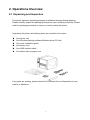
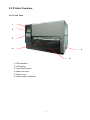
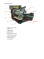
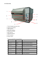
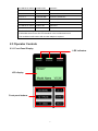
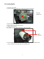
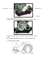
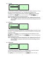
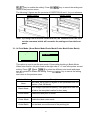
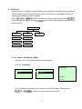
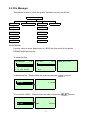
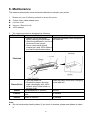
kroy K8300 series THERMAL TRANSFER / DIRECT THERMAL BAR CODE PRINTER USER’S MANUAL Contents 1. Introduction ............................................ 1 1.1 Product Introduction ............................................................................... 1 1.2 Compliances ............................................................................................ 1 2. Operations Overview ..................................... 3 2.1 Unpacking and Inspection ...................................................................... 3 2.2 Printer Overview ...................................................................................... 4 2.2.1 Front View ...................................................................................... 4 2.2.2 Interior view .................................................................................... 5 2.2.3 Rear View........................................................................................ 6 2.3 Operator Controls .................................................................................... 7 2.3.1 Front Panel Display ....................................................................... 7 2.3.2 LED Indicators ............................................................................... 8 2.3.3 Front Panel Keys ........................................................................... 8 2.4 Setting Up the Printer .............................................................................. 8 2.5 Loading Ribbon........................................................................................ 9 2.6 Loading Media ........................................................................................ 12 3. Menu Function ......................................... 14 3.1 Setup Menu Overview............................................................................ 15 3.1.1 Printer Setup ................................................................................ 16 3.1.2 Sensor........................................................................................... 23 3.1.3 Serial Comm. ................................................................................ 31 3.1.4 Ethernet ........................................................................................ 34 3.2 File Manager ........................................................................................... 37 3.2.1 File List ......................................................................................... 37 3.2.2 Avail. Memory ............................................................................... 38 3.2.3 Del. All Files.................................................................................. 38 3.3 Diagnostics ............................................................................................ 39 3.3.1 Print Config. ................................................................................. 39 3.3.2 Dump Mode .................................................................................. 40 3.3.3 Rotate Cutter ................................................................................ 41 3.4 Language ................................................................................................ 41 3.5 Service .................................................................................................... 42 3.5.1 Initialization .................................................................................. 42 3.5.2 Mileage Info. ................................................................................. 43 4. Diagnostic Tool ......................................... 44 i 4.1 Start the Diagnostic Tool ....................................................................... 44 4.2 Printer Function (Calibrate sensor, Ethernet setup, RTC setup………) ....................................................................................................................... 45 5. Troubleshooting ........................................ 46 5.1 Common Problems ................................................................................ 46 6. Maintenance ........................................... 50 ii 1. Introduction 1.1 Product Introduction Thank you very much for purchasing this thermal transfer label printer. This printer is designed with die-casting aluminum chassis and print mechanism, metal cover with large clear media view window, which ensuring to work for the extreme and heavy duty industrial environment and applications. With a back-lit graphic LCD display, the printer status is user friendly and can be easily managed. The moveable sensor design can accept wide range of label media. All of the most frequently used bar code formats are included. Fonts and bar codes can be printed in any one of the four directions. This printer is built-in the high quality, high performance MONOTYPE IMAGING® True Type font engine and one CG Triumvirate Bold Condensed smooth font. With flexible firmware design, users can also download True Type Fonts from a PC into the printer memory for printing labels. In addition to the scalable font, there is also a choice of five different sizes of alphanumeric bitmap fonts, OCR-A and OCR-B fonts. By integrating rich features, it is the most cost-effective and high performance printer in its class! 1.2 Compliances CE Class A: EN55022:1998+A1:2000+A2:2003: EN55024:1998+A1:2001+A2:2003: EN 61000-4 SERIES REQULATIONS ETSI EN 301 489-17:V1.2.1(2002-08) FCC: CFR 47, Part 15/CISPR 22 3RD EDITION:1997, Class A UL, CUL UL 60950-1 1st TÜV-GS: IEC60950-1: 2001 EN 60950-1/A11:2004 Wichtige Sicherheits-Hinweise 1.Bitte lesen Sie Diese Hinweis sorgfältig durch 2.Heben Sie diese Anleitung fűr den späteren Gebrauch auf. 3.Vor jedem Reinigen ist das Gerät vom Stromentz zu trennen. Verwenden Sie Keine Flűssig-oder Aerosolreiniger. Am besten eignet sich ein angefeuchtetes Tuch zur Reinigung. 4.Die Netzanschlußsteckdose soll nahe dem Gerät angebraucht und leicht zugänglich sein. 5.Das Gerät ist vor Feuchtigkeit zu schűtzen. 6.Bei der Aufstellung des Gerätes ist auf sicheren Stand zu achten. Ein Kippen oder Fallen könnte Beschädigungen hervorrufen. 7.Beáchten Sie beim Anschluß an das stromnetz die Anschlußwerte. 8. Dieses das Gerät kann bis zu einer Außentemperatur von maximal 40℃ betieben werden. 2 2. Operations Overview 2.1 Unpacking and Inspection This printer has been specially packaged to withstand damage during shipping. Please carefully inspect the packaging and printer upon receiving the printer. Please retain the packaging materials in case you need to reship the printer. Unpacking the printer, the following items are included in the carton. One printer unit One Windows labeling software/Windows driver CD disk One quick installation guide One power cord One USB interface cable One ribbon take up paper core If any parts are missing, please contact the Customer Service Department of your reseller or distributor. 3 2.2 Printer Overview 2.2.1 Front View 1 2 3 4 5 6 1. LED indicators 2. LCD display 3. Front panel buttons 4. Paper exit chute 5. Printer cover 6. Cutter module (Optional) 4 2.2.2 Interior view 7 1 8 2 3 4 5 9 10 6 1. Ribbon rewind spindle 2. Printhead 3. Ribbon sensor 4. Media sensor 5. Platen roller 6. Printhead release lever 7. Ribbon supply spindle 8. Label supply spindle 9. Media guide bar 10. Label guide 5 2.2.3 Rear View 1 6 2 7 3 8 4 9 5 1. Fan-fold paper entrance chute 2. Centronics interface 3. USB interface 4. RS-232C interface 5. Power jack socket *6. SD card slot 7. Ethernet interface 8. PS/2 interface 9. Power switch * Recommended SD card specification. SD card spec SD card capacity Approved SD card manufacturer V1.0, V1.1 128 MB SanDisk, Transcend V1.0, V1.1 256 MB SanDisk, Transcend, Panasonic V1.0, V1.1 512 MB SanDisk, Transcend, Panasonic V1.0, V1.1 1 GB SanDisk, Transcend, Panasonic V2.0 SDHC CLASS 4 4 GB V2.0 SDHC CLASS 6 4 GB SanDisk, Transcend, Panasonic V1.0, V1.1 microSD 128 MB Transcend, Panasonic V1.0, V1.1 microSD 256 MB Transcend, Panasonic V1.0, V1.1 microSD 512 MB Panasonic V1.0, V1.1 microSD 1 GB Transcend, Panasonic 6 V2.0 SDHC CLASS 4 microSD 4 GB Panasonic V2.0 SDHC CLASS 6 microSD 4 GB Transcend V1.0, V1.1 miniSD 128 MB Transcend, Panasonic V1.0, V1.1 miniSD 256 MB Transcend, Panasonic V1.0, V1.1 miniSD 512 MB Transcend, Panasonic V1.0, V1.1 miniSD 1 GB Transcend, Panasonic V2.0 SDHC CLASS 4 miniSD 4 GB Transcend V2.0 SDHC CLASS 6 miniSD 4 GB - The DOS FAT file system is supported for the SD card. - Folders/files stored in the SD card should be in the 8.3 filename format - The miniSD/microSD card to SD card slot adapter is required. 2.3 Operator Controls 2.3.1 Front Panel Display LED indicators LCD display Front panel buttons 7 2.3.2 LED Indicators LED Status Indication Off Printer power off On Printer power on On Printer is ready Blinking Printer is paused Printer is downloading data Off Printer is ready On Carriage open OR Cutter error Blinking No paper, Paper jam OR "No ribbon 2.3.3 Front Panel Keys Keys Function 1. Enter the menu system 2. Once in the menu system, return to previous menu. If at menu root, exits the menu system. Pauses or resumes printing Advance one label Scroll up the menu options Scroll down the menu options Select the currently highlighted option 2.4 Setting Up the Printer 1. Place the printer on a flat, secure surface. 2. Make sure the power switch is off. 3. Connect the printer to the computer with the provided USB cable. 4. Plug the power cord into the AC power cord socket at the rear of the printer, and then plug the power cord into a properly grounded power outlet. 8 2.5 Loading Ribbon 1. Lift printer cover open. 2. Push the printhead release lever to open the printhead mechanism. Printhead release lever 3. Install the ribbon onto the ribbon supply spindle. Note: Make sure the ribbon is set at the center of the spindle. 4. Install the paper core onto the ribbon rewind spindle. Note: Make sure the paper core is set at the center of the spindle. 9 5. Thread the ribbon through the ribbon sensor slot and printhead. Ribbon Ribbon sensor 5. Stick ribbon onto ribbon rewind paper core, keeping the ribbon flat and wrinkle-free. 6. Wind the ribbon rewind spindle clockwise roughly 3~5 circles until ribbon is smooth, taut and wrinkle-free. 7. Close the printhead mechanism, making sure the latches are engaged properly. 10 z Loading path for ribbon 11 2.6 Loading Media 1. Lift printer cover open. 2. Push the printhead release lever to open the printhead mechanism. Printhead release lever 3. Remove ONE label rollguard. 4. Place media roll on label supply spindle. 5. Replace label rollguide. Note: Make sure the media is set at the center of spindle. Label rollguides 6. Pull the leading edge of the label forward through the media guide bar past media sensor, and place the leading edge onto the platen roller. 12 Media sensor Media guide bar Label guide 7. Adjust the label guide to fit label width. 8. Close printhead mechanism, making sure the latches are engaged properly. 9. Using the front display panel, set media sensor type and calibrate the selected sensor. Note: Re-calibrate the gap/black-mark sensors when changing media. z Loading path for roll labels 13 3. Menu Function Main Menu Overview Main Menu Setup F ile Manager Diagnostics Language Serv ice ↓ Printer Setup ↓ File List ↓ Print Config. ↓ English ↓ Initialization ↓ Sensor ↓ Dump Mode ↓ Chinese(TC) ↓ Mileage Info. ↓ Serial Comm. ↓ Avail. Memory ↓ Del. All F iles ↓ Rotate Cutter ↓ Chinese(SC) ↓ Exit ↓ *Ethernet ↓ Exit ↓ Exit ↓ Japanese ↓ Exit Exit ↓ German ↓ Italian ↓ French ↓ Russian ↓ Polish ↓ Spanish ↓ Exit Note: * Ethernet function is available on the LCD display when an Ethernet card is installed. 14 3.1 Setup Menu Overview Setup Printer Setup Sensor Serial Comm. Ethernet ↓ TSPL2 ↓ Status ↓ Baud Rate ↓ Status ↓ Z PL2 ↓ Calibration ↓ Parity ↓ Configure ↓ Exit ↓ Exit ↓ Data Bits ↓ Exit Exit ↓ Stop Bit(s) ↓ Exit Note: * Ethernet function is available on the LCD display when an Ethernet card is installed. 15 3.1.1 Printer Setup Printer Setup TSPL2 Speed Density Direction ↓ 4 5 6 7 8 9 10 11 12 ↓ 0 1 2 3 4 5 6 7 8 9 10 11 12 13 14 15 ↓ 0 1 Print Mode Offset ↓ None Batch Mode Peeler Mode Cutter Mode Cutter Exit ↓ +000~- Shift X Shift Y ↓ +000~-000 +000~-000 16 Reference X Reference Y Code Page Country ↓ 000~999 ↓ 000~999 ↓ USA BRI GER FRE DAN ITA SPA SWE SWI 437 850 852 860 863 865 857 1252 1250 1253 1254 1251 1255 1256 1257 1258 8859-1 8859-2 8859-3 8859-4 8859-5 8859-6 8859-7 8859-8 8859-9 8859-10 8859-15 950 936 932 949 ↓ 001 002 003 031 032 033 034 036 038 039 041 042 044 045 046 047 048 049 055 061 351 358 Exit Exit 3.1.1.1 Speed: Print Setup 1/12 Speed > Speed 6 Density Direction Use this option to setup print speed. The available print speed is between 4~12 ips and each increment/decrement is 1 ips. The default print speed is 6 ips. Press key to raise the print speed, and press key to decrease print speed. Press key to set it into printer. Press cancel the setting and return to the previous menu. key to Note: If printing from enclosed software/driver, the software/driver will send out the SPEED command, which will overwrite the setting set from the front panel. 3.1.1.2 Density: Print Setup 2/12 Speed Density > Density 8 Direction Use this option to setup printing darkness. The available setting is from 0 to 15, and the step is 1. Printer default density is 8.You may need to adjust your density based on selected media. Press and to increase/decrease the printing darkness. Press key to enable the setting. Press return to the previous menu. key to cancel the setting and Note: If printing from enclosed software/driver, the software/driver will send out the DENSITY command, which will overwrite the setting set from the front panel. 3.1.1.3 Direction: Print Setup Speed 3/12 Direction Density 0 > Direction The direction setting value is either 1 or 0. Use this option to setup the printout direction. Printer default printout direction is DIRECTION 0. Press key to set the direction as 1, and 17 to set it as 0, and key to enable the setting. Press key to cancel the setting and return to the previous menu. The following 2 figures are the printouts of DIRECTION 0 and 1 for your reference. DIRECTION 0 DIRECTION 1 Note: If printing from enclosed software/driver, the software/driver will send out the command, which will overwrite the setting set from the front panel. 3.1.1.4 Print Mode: (None/Batch Mode/Peeler Mode/Cutter Mode/Cutter Batch) Print Setup Density 4/12 Print Mode 2/6 > Batch Mode Direction Peeler Mode > Print Mode Cutter Mode This option is used to set the print mode. Printer default setting is Batch Mode. When enter this list, the print mode in the right side of " >" icon is the printer current and to select the different print mode and press setting. Press button to enable the setting. Press and return to the previous menu. key to cancel the setting Printer Mode Description None Next label top of form is aligned to the printhead burn line location. (Tear Off Mode) Batch Mode Once image is printed completely, label gap/black-mark will be fed to the tear plate location for tear away. Peeler Mode Enable the label peel off mode. Cutter Mode Enable the label cutter mode. Cutter Batch Cut the label once at the end of the printing job. 18 Note: If printing from enclosed software/driver, the software/driver will send out the command, which will overwrite the setting set from the front panel. 3.1.1.5 Offset: Print Setup 5/12 Direction Offset Print Mode +000 > Offset This option is used to fine tune media stop location. Press the move the cursor from left digit to right digit, and press the button to button to set the value from “+” to “-” or “0” to “9”. Press the button to set the value into printer. Press key to cancel the setting and return to the previous menu. The default value is +000. Note: If printing from enclosed software/driver, the software/driver will send out the OFFSET command, which will overwrite the setting set from the front panel. 3.1.1.6 Shift X & Shift Y: Print Setup 7/12 Offset Shift Y Shift X +000 > Shift Y This option is used to fine tune print position. Press the the cursor from left digit to right digit, and press the button to move button to set the value from “+” to “-” or “0” to “9”. Press the button to set the value into printer. key to cancel the setting and return to the previous menu. The Press default value is +000. Note: If printing from enclosed software/driver, the software/driver will send out the SHIFT command, which will overwrite the setting set from the front panel. 3.1.1.6 Reference X & Reference Y: Print Setup Shift Y Reference X 9/12 Reference Y 000 > Reference Y 19 This option is used to set the origin of printer coordinate system horizontally and vertically. Press the button to move the cursor from left digit to right digit, button to set the value from “0” to “9”. Press the and press the button to set the value into printer. Press key to cancel the setting and return to the previous menu. The default value is 000. Note: If printing from enclosed software/driver, the software/driver will send out the REFERENCE command, which will overwrite the setting set from the front panel. 3.1.1.7 Code Page: Print Setup 10/12 Code Page Reference X > 850 Reference Y 852 11/41 860 > Code Page Use this option to set the code page of international character set. For more information about code page, please to refer the programming manual. When enter the code page list, the code page in the right side of ">" icon is the printer current setting. Press the and to select the code page, and press the key to cancel the setting and return button to enable the setting. Press to the previous menu. Note: If printing from enclosed software/driver, the software/driver will send out the command, which will overwrite the setting set from the front panel. 7-bit 8-bit code page name International Character Set code page number International Character Set USA USA 437 United States BRI British 850 Multilingual GER German 852 Slavic FRE French 860 Portuguese DAN Danish 863 Canadian/French ITA Italian 865 Nordic SPA Spanish SWE Swedish SWI Swiss 20 Windows Code Page (SBCS) Windows Code Page (DBCS) code page number International Character Set code page number International Character Set 1252 Latin 1 950 Traditional Chinese Big5 1250 Central Europe 936 Simplified Chinese GBK 1253 Greek 932 Japanese Shift-JIS 1254 Turkish 949 Korean 1251 Cyrillic 1255 Hebrew 1256 Arabic 1257 Baltic 1258 Vietnam ISO Code Page ISO Code Page code page name International Character Set code page number International Character Set 8859-1 Latin 1 8859-7 Greek 8859-2 Latin 2 8859-9 Turkish 8859-3 Latin 3 8859-10 Latin 6 8859-4 Baltic 8859-15 Latin 9 8859-5 Cyrillic 3.1.1.8 Country: Print Setup Reference Y Code Page > Country 11/12 Country 1/23 > 001 002 003 Use this option to set the country code for the LCD display. Press the and to select the country code, and press the button to set the value into printer. When enter this list, the country code in the right side of ">" icon key to cancel the setting and return is the printer current setting. Press to the previous menu. 21 Code Country Code Country Code Country Code Country 001 USA 034 Spanish (Spain) 044 United Kingdom 055 Brazil 002 Canadian-French 036 Hungarian 045 Danish 061 English (International) 003 Spanish (Latin America) 038 Yugoslavian 046 Swedish 351 Portuguese 031 Dutch 039 Italian 047 Norwegian 358 Finnish 032 Belgian 041 Switzerland 048 Polish 033 French (France) 042 Slovak 049 German 22 3.1.2 Sensor Sensor Status C alibration Exit 3.1.2.1 Status This function is available to check the printer’s sensor status. When enter the [Status] option, you will see following message. Paper Len. 812 Gap Size 24 Intensity 3 Ref. Level 512 3.1.2.2 Calibration This option is used to set the media sensor type and calibrate the selected sensor. We recommend to calibrate the sensor before printing when changing the media. Calibration Gap Mod e Bline Mode Cont. Mode ↓ Automatic ↓ Automatic ↓ Automatic ↓ Manual ↓ Manual ↓ Manual ↓ Pre-Printed ↓ Pre-Printed ↓ Exit ↓ Exit ↓ Exit 23 Exit A. Gap Mode Calibration 1/4 > Gap Mode Gap Mode 1/4 > Automatic Bline Mode Manual Cont. Mode Pre-Printed Press the the and buttons to scroll the cursor to the media type and press button to enter the sensor calibration mode. Note: If printing from enclosed software/driver, the software/driver will send out the GAP or BLINE command, which will overwrite the sensor type setting set from the front panel. A-1 Automatic When enter the [Automatic] option, you will see following message, and printer will feed 2 to 3 gap labels to calibrate the sensor sensitivity automatically. When calibration is completed, the LCD screen will return to the previous menu. Gap Mode Automatic A-2 Manual In case “Automatic” sensor calibration cannot apply to the media, please use “Manual” function to calibrate the gap sensor manually. Gap Mode 2/4 Automatic > Manual Pre-Printed When enter [Manual] option, you will see following message. Please complete there steps: Paper Len. 00812 dot 1. Press the button to move the cursor from left digit to right digit, and press the button to set the value from “0” to “9” and the “dot/ mm/ inch”. Press the button to set the paper length into the printer. 24 Gap Size 0024 dot Gap Mode Scan Backing Intensity Ref. Level x xxx 4. Then, Put the label with liner under the media sensor. Press the button to set the value into the printer. Gap Mode Scan Paper Intensity Ref. Level x xxx Gap Mode Complete Intensity Ref. Level 2. Press the button to move the cursor from left digit to right digit, and press the button to set the value from “0” to “9” and the “dot/ mm/ inch”. Press the button to set the gap size into the printer. 3. Open the printhead mechanism, put the label backing (liner) under the media sensor. Press the button to set the value into the printer. x 5. The gap sensor calibration is complete. Press the button the LCD screen will return to the previous menu. xxx A-3 Pre-Printed This function can set the paper length and gap size before auto-calibrate the sensor sensitivity. It can to get the sensor sensitivity accurately. Gap Mode 3/4 Manual > Pre-Printed Exit When enter [Pre-Printed] option, you will see following message. Please complete there steps: Paper Len. 00812 dot 1. Press the button to move the cursor from left digit to right digit, and press the button to set the value from “0” to “9” and the “dot/ mm/ inch”. Press the button to set the paper length into the printer. 25 Gap Size 0024 dot Gap Mode Pre-Printed 2. Press the button to move the cursor from left digit to right digit, and press the button to set the value from “0” to “9” and the “dot/ mm/ inch”. Press the button to set the gap size into the printer. 3. Then, printer will feed labels to calibrate the sensor sensitivity automatically. When calibration is completed, the LCD screen will return to the previous menu. 26 B. Bline Mode Calibration 2/4 Gap Mode Bline Mode > Automatic > Bline Mode Manual Cont. Mode Press the the 1/4 Pre-Printed and buttons to scroll the cursor to the sensor type. Press button to enter the black-mark sensor calibration mode. B-1 Automatic When enter the [Automatic] option, you will see following message and printer will feed the black-mark label to calibrate the sensor sensitivity automatically. When calibration process is completed, the LCD screen will return to the previous menu. Bline Mode Automatic B-2 Manual In case “Automatic” sensor calibration cannot apply to the media, please use “Manual” function to calibrate the bline sensor manually. Bline Mode 2/4 Automatic > Manual Pre-Printed When enter [Manual] option, you will see following message. Please complete there steps: Paper Len. 00151 dot Bline Size 0024 dot 1. Press the button to move the cursor from left digit to right digit, and press the button to set the value from “0” to “9” and the “dot/ mm/ inch”. Press the button to set the paper length into the printer. 2. Press the button to move the cursor from left digit to right digit, and press the button to set the value from “0” to “9” and the “dot/ mm/ inch”. Press the button to set the bline size into the printer. 27 Bline Mode Scan Mark Intensity Ref. Level x xxx Bline Mode Scan Paper Intensity Ref. Level 3. Open the printhead mechanism, put the black-mark under the media button sensor. Press the to set the value into the printer. x 4. Then, put the label without black-mark under the media sensor. Press the button to set the value into the printer. xxx Note: Normally, the value of “Ref. Level” for mark should be larger than paper for over 128. If the media sensor fails to do so, you have to manually change the Intensity by pressing and to reach the above value. Bline Mode Complete Intensity Ref. Level x 5. The bline sensor calibration is complete. Press the button the LCD screen will return to the previous menu. xxx B-3 Pre-Printed This function can set the paper length and gap size before auto-calibrate the sensor sensitivity. It can to get the sensor sensitivity accurately. Bline Mode 3/4 Manual > Pre-Printed Exit When enter [Pre-Printed] option, you will see following message. Please complete there steps: Paper Len. 00812 dot Bline Size 0024 dot 1. Press the button to move the cursor from left digit to right digit, and press the button to set the value from “0” to “9” and the “dot/ mm/ inch”. Press the button to set the paper length into the printer. 2. Press the button to move the cursor from left digit to right digit, and press the button to set the value from “0” to “9” and the “dot/ mm/ inch”. Press the button to set the bline size into the printer. 28 Bline Mode Pre-Printed 3. Then, printer will feed labels to calibrate the sensor sensitivity automatically. When calibration is completed, the LCD screen will return to the previous menu. 29 C. Cont. Mode Calibration 3/4 Bline Mode 1/3 > Automatic > Cont. Mode Manual Exit Exit Press the the Cont. Mode and buttons to scroll the cursor to the sensor type. Press button to enter the black-mark sensor calibration mode. C-1 Automatic When enter the [Automatic] option, you will see following message and printer will calibrate the sensor sensitivity automatically. When calibration process is completed, the LCD screen will return to the previous menu. Cont. Mode Automatic C-2 Manual In case “Automatic” sensor calibration cannot apply to the media, please use “Manual” function to calibrate the sensor manually. Cont. Mode 2/3 Automatic > Manual Exit When enter [Manual] option, you will see following message. Please complete there steps: 1. Remove the continuous label. Press button to set the value the into the printer. Cont. Mode Remove Label Intensity Ref. Level x xxx Cont. Mode Scan Paper Intensity Ref. Level x 2. Then, put the continuous label under the media sensor. Press the button to set the value into the printer. xxx 30 Cont. Mode Complete Intensity x Ref. Level 3. The sensor calibration is complete. button the LCD Press the screen will return to the previous menu. xxx 3.1.3 Serial Comm. Seria l Comm. Baud Ra te Parity Data Bits Stop Bit(s) ↓ 1200 bps ↓ None ↓ 7 ↓ 1 ↓ 2400 bps ↓ Odd ↓ 8 ↓ 2 ↓ 4800 bps ↓ Even ↓ Exit ↓ Exit ↓ 9600 bps ↓ Exit ↓ 19200 b ps ↓ 38400 b ps ↓ 57600 b ps ↓ 115200 bps ↓ Exit 31 Exit 3.1.3.1 Baud Rate Serial Comm. 1/5 > Baud Rate Baud Rate 4/9 > 9600 bps Parity 19200 bps Data Bits 38400 bps This option is used to set the RS-232 baud rate. The default setting is 9600 bps. Press and buttons to select the different baud rate and press button to set the value into printer. When you enter this list, the baud rate value in the right side of ">" icon is the current setting in the printer. Press key to cancel the setting and return to the previous menu. 3.1.3.2 Parity Serial Comm. 2/5 Baud Rate Parity 1/4 > None > Parity Odd Data Bits Even This option is used to set the RS-232 parity. The default setting is “None”. Press and buttons to select the different parity and press button to set the value into printer. When you enter this list, the parity in the right side of ">" is the printer current setting. Press and return to the previous menu. key to cancel the setting 3.1.3.3 Data Bits: Serial Comm. 3/5 Baud Rate Data Bits 2/3 7 Parity > 8 > Data Bits Exit This option is used to set the RS-232 Data Bits. The default setting is “8” data bits. Press and buttons to select the different Data Bits and press button to set the value into printer. When you enter this list, the Data Bits in the right side of ">" icon is the printer current setting. Press key to cancel the setting and return to the previous menu. 32 3.1.3.4 Stop Bit(s): Serial Comm. 4/5 Parity Stop Bit(s) 1/3 > 1 Data Bits 2 > Stop Bit(s) Exit This option is used to set the RS-232 Stop Bits. The default setting is “1” stop bit. Press and buttons to select the different Stop Bits and press button to set the value into printer. When you enter this list, the option in the right side of ">" icon is the printer current setting. Press key to cancel the setting and return to the previous menu. 33 3.1.4 Ethernet Use this menu to configure internal Ethernet configuration check the printer’s Ethernet module status, and reset the Ethernet module. This function is available on the LCD display when Ethernet card is installed. and buttons to select the different options and press Press button to enter the option. Press key to cancel the setting and return to the previous menu. Ethernet Status Configure ↓ IP Address ↓ DHCP ↓ MAC ↓ Static IP ↓ Exit ↓ Exit Exit 3.1.4.1 Status: (IP Address / MAC) Use this menu to check the Ethernet setting status. 3.1.4.1.1 IP Address IP Address Ethernet 1/3 > Status Status 1/3 > IP Address 0.0.0.0 Subnet Mask Configure MAC 0.0.0.0 Exit Exit Gateway 0.0.0.0 The IP address information will be shown on the LCD display. Please press or button to return to the previous menu. 34 3.1.4.1.2 MAC Ethernet 1/3 Status > Status 2/3 IP Address Configure MAC Address 001B82-FF0918 > MAC Exit Exit The MAC address information will be shown on the LCD display. Please press or button to return to the previous menu. 3.1.4.2 Configure: (DHCP / Static IP) Use this menu to set the printer's DHCP and Static IP. 3.1.4.2.1 DHCP Ethernet 2/4 Status Configure 1/3 > DHCP > Configure Static IP Reset Exit Press and buttons to select the DHCP function and press to enter. Press previous menu. key to cancel the setting and return to the DHCP SELECT: YES MENU: NO Press Press button the printer will set DHCP and restart to reset the setting. button to return to the previous menu. 35 3.1.4.2.2 Static IP Use this menu to set the printer's IP address, subnet mask and gateway. Ethernet 2/3 Status Configure 2/3 DHCP > Configure > Static IP Exit Exit Press and buttons to select the different options and press button to enter the option. Press return to the previous menu. key to cancel the setting and IP Address Subnet Mask Gateway 000.000.000.000 000.000.000.000 000.000.000.000 Press button to move the cursor from left to right digits and press the button to scroll the value from “0” to “9”. Press setting. button to next Static IP SELECT: YES MENU: NO Press the Press button printer will restart to reset the Ethernet module setting. key to cancel the setting. 36 3.2 File Manager This feature is used to check the printer available memory and file list. File Mana ger File List Avail. Memory Del. All Files ↓ DRAM ↓ DRAM ↓ FLASH ↓ FLASH ↓ CARD ↓ CARD ↓ Exit ↓ Exit Exit 3.2.1 File List Use this menu to show, delete and run (.BAS) the files saved in the printer DRAM/Flash/Card memory. To show the files: File Manager > File List 1/4 File List 2/4 > FLASH Avail. Memory CARD Del. All Files Exit FLASH File List > DEMO.TTF DEMO.BAS To delete the file:Please follow the order to press the FLASH File List button. DEMO.TTF > DEMO.TTF 1.75 MB DEMO.BAS DOWN: Delete To run the file (.BAS):Please follow the order to press the FLASH File List DEMO.BAS DEMO.TTF > DEMO.BAS 406 Byte(S) DOWN: Delete SELECT: Run 37 button. 3.2.2 Avail. Memory Use this menu to show available memory space. File Manager 2/4 File List Avail. Memory DRAM: > Avail. Memory 256 KB FALSH: Del. All Files 6656 KB CARD: 0 KB 3.2.3 Del. All Files Use this menu to delete all files. Press button to delete all files in the device. Press to cancel deleting files and go back to previous menu. File Manager File List Avail. Memory > Del. All File 3/4 File List 1/4 Del. All Files > DRAM FALSH SELECT: CARD MENU: 38 YES NO 3.3 Diagnostics Diagnostics Print Config. Dump Mod e Rotate Cutter Exit 3.3.1 Print Configuration. This feature is used to print current printer configuration to the label. On the configuration printout, there is a printhead test pattern, which is useful for checking if there is any dot damage on the printhead heater element. Diagnostics 1/4 Self Test ... > Print Config. Printing ... 1/1 Dump Mode Rotate Cutter Self-test printout Printhead check pattern Model name and F/W version Printed mileage (meter) Firmware checksum Serial port configuration Code page Country code Print speed (inch/sec) Print darkness Label size (inch) Gap distance (inch) Gap/black-mark sensor sensitivity Numbers of download files Total & available memory space 39 3.3.2 Dump Mode Captures the data from the communications port and prints out the data received by printer. In the dump mode, all characters will be printed in 2 columns as following. The left side characters are received from your system and right side data are the corresponding hexadecimal value of the characters. It allows users or engineers to verify and debug the program. Diagnostics 2/4 Printing ... Pritn Config. Dump Mode 1/1 > Dump Mode Rotate cutter Note: 1. Dump mode requires 4” wide paper width. 2. Turn off / on the power to resume printer for normal printing. 3. Press FEED button to back to the previous menu. DOWNLOA D "TEST2. DAT",5,CL S DOWNLO AD F,"TES T4.DAT",5 ,CLS DOW NLOAD "TE ST2.DAT", 5,CLS DO WNLOAD F, "TEST4.DA T",5,CLS DOWNLOAD "TEST2.D AT",5,CLS DOWNLOA D F,"TEST 4.DAT",5, CLS 0D 44 44 53 41 54 2C 4E 53 35 57 22 54 0A 20 41 0D 44 34 43 0A 20 41 0D 44 34 43 4C 54 2C 4E 54 22 44 22 54 0A 20 2E 4C 44 22 54 0A 20 2E 4C 4F 32 43 4C 45 2C 4F 54 22 44 46 44 53 4F 54 22 44 46 44 53 41 2E 4C 4F 53 35 57 45 2C 4F 2C 41 0D 57 45 2C 4F 2C 41 0D 44 44 53 41 54 2C 4E 53 35 57 22 54 0A 4E 53 35 57 22 54 0A 20 41 0D 44 34 43 4C 54 2C 4E 54 22 4C 54 2C 4E 54 22 44 22 54 0A 20 2E 4C 4F 32 43 4C 45 2C 4F 32 43 4C 45 2C 4F 54 22 44 46 44 53 41 2E 4C 4F 53 35 4I 2E 4C 4F 53 35 57 45 2C 4F 2C 41 0D 44 44 53 4I 54 2C ASCII Data Hexdecimal data related to the left column of the ASCII data 40 3.3.3 Rotate Cutter In case the meida is jammed in the cutter, this feature can rotate the cutter blade forward or reverse direction, which is helpful to remove the jammed material easily from the cutter. Diagnostics 3/4 Print Config. UP: Fwd. DOWN: Rev. Dump Mode > Rotate Cutter MENU: Exit 3.4 Language Language English Chinese (TC) Chinese (SC) Japanese G erman Italian French Russian Polish Spanish Exit This option is used to setup the language on LCD display. Press and buttons to scroll the curser to desire language and press button to select this option. Press key to cancel the setting and return to the previous menu. The default language setting is English. 41 3.5 Service Service Initialization Mileage Info. Exit This feature is used to restore printer settings to defaults and display printer mileage information. 3.5.1 Initialization Service 1/3 Initialization Initializing ... > Initialization Mileage Info. SELECT Exit MENU YES NO The printer settings are restored to defaults as below once printer is initialized. Note : When printer initialization is done, please calibrate the gap or black-mark sensor before printing. Parameter Default setting Speed 2 IPS (50.8 mm/sec) Density 8.0 Label width 8.64"(219.5mm) Label height 4.00"(101.6mm) Sensor type Gap sensor Gap setting 0.12"(3.0mm) Print direction 0 Reference point 0,0(upper left corner) Offset 0 Print mode Batch mode Serial port settings 9600 bps, none parity, 8 data bits, 1 stop bit Code page 850 Country code 001 Clear flash memory No Shift X 0 Shift Y 0 Gap sensor sensitivity 3 (Will be reset. Need to re-calibrate the gap) 42 Bline sensor sensitivity 2 (Will be reset. Need to re-calibrate the gap) Language English IP address DHCP 3.5.2 Mileage Info. Use this option to check the printed mileage (displayed in meter). Service 1/3 Mileage:(m) Initialization > Mileage Info. 4016 Labels: (pcs.) Exit 51698 43 4. Diagnostic Tool The Diagnostic Utility toolbox allows users to explore and change printer status and settings. Download graphics, fonts, firmware to the printer can be accomplished using this utility, as well as creating bitmap fonts. The Diagtools can be used to send additional commands to the printer and troubleshoot any issues during use. Note: The Diagnostic Utility requires printer firmware V6.00 and above. 4.1 Start the Diagnostic Tool 1. Double click the Diagnostic tool icon ( ) to start the software. 2. Four features (Printer Configuration, File Manager, Bitmap Font Manager, Command Tool) are included in the Diagnostic utility. Features tab Interface Printer functions Printer setup Printer Status 44 4.2 Printer Function (Calibrate sensor, Ethernet setup, RTC setup………) 1. Select the PC interface connected with bar code printer. 2. Click the “Function” button to setting. 3. The Printer Functions group provides the following options: Function Description Factory Default Initializes the printer, restoring factory default settings. Dump Text Activates printer dump mode. Configuration Page Prints printer configuration. RTC Setup Setup printer’s Real Time Clocks. Calibrate Sensor Calibrates the sensor to the specifications of the Printer Setup group media sensor field. Reset Printer Reboots the printer. Print Test Page Prints a test page. Ignore AUTO.BAS Disregards the downloaded AUTO.BAS program upon printer startup. Ethernet Setup Setup Ethernet settings. Note: For more information about Diagnostic Tool, please refer to the diagnostic utility quick start guide in the CD disk \ Utilities directory. 45 5. Troubleshooting 5.1 Common Problems The following guide lists the most common problems that may be encountered when operating this bar code printer. If the printer still does not function after all suggested solutions have been invoked, please contact the Customer Service Department of your purchased reseller or distributor for assistance. Problem Possible Cause Recovery Procedure Power indicator does * The power cord is not properly connected. not illuminate * Plug the power cord in printer and outlet. * Switch the printer on. Carriage Open * The printer carriage is open. * Please close the print carriage. * Running out of ribbon. * The ribbon is installed incorrectly. * Supply a new ribbon roll. * Please refer to the steps in user’s manual to reinstall the ribbon. * Running out of label. * The label is installed incorrectly. * Gap/black-mark sensor is not calibrated. * Supply a new label roll. * Please refer to the steps in user’s manual to reinstall the label roll. * Calibrate the gap/black-mark sensor. No Ribbon No Paper * Gap/black-mark sensor is not set properly. * Calibrate the gap/black-mark sensor. * Make sure label size is set properly. * Set label size correctly. * Labels may be stuck inside the printer mechanism. Paper Jam UP: Fwd. DOWN: Rev. MENU: Exit * Cutter jam. * There is no cutter installed on the printer. * Cutter PCB is damaged. 46 * If the cutter module is installed, please press UP or DOWN key to rotate the cutter up or down to make the knife back to the right position. * Remove the label. * Make sure the thickness of label is less than 0.254 mm (10mil) * Replace a cutter PCB. * Re-connect cable to interface. * If using serial cable, - Please replace the cable with pin to pin connected. - Check the baud rate setting. The default baud rate setting of printer is 9600,n,8,1. * If using the Ethernet cable, - Check if the Ethernet RJ-45 connector green LED is lit on.. - Check if the Ethernet RJ-45 connector amber LED is blinking. - Check if the printer gets the IP address when using DHCP mode. - Check if the IP address is correct when using * Cable is not well connected to serial or the static IP address. USB interface or parallel port. Wait a few seconds let the printer get the Not Printing * The serial port cable pin configuration communication with the server then check the is not pin to pin connected. IP address setting again. * Chang a new cable. * Ribbon and media are not compatible. * Verify the ribbon-inked side. * Reload the ribbon again. * Clean the printhead. * The print density setting is incorrect. * Printhead’s harness connector is not well connected with printheat. Turn off the printer and plug the connector again. * Check if the stepping motor is plugging in the right connector. * Check your program if there is a command PRINT at the end of the file and there must have CRLF at the end of each command line. * Delete unused files in the FLASH/DRAM. * The max. numbers of file of DRAM is 256 files. * The max. user addressable memory space of Memory full * The space of FLASH/DRAM is full. DRAM is 2048 KB. ( FLASH / DRAM ) * The max. numbers of file of FLASH is 256 files. * The max. user addressable memory space of FLASH is 6656KB. * Use the supported capacity SD card. * Insert the SD card again. * The supported SD card spec. * SD card is damaged. - 128MB SD card is unable to * SD card doesn’t insert correctly. - 256MB * Use the non-approved SD card - 512MB use manufacturer. - 1GB - 4GB SDHC CLASS 6 * Approved SD card manufacturers; SanDisk, Transcend * Did not turn off power prior to plug in * Turn off printer power prior to plug in the PS/2 keyboard . the PS/2 keyboard. PS/2 port does not * PS/2 keyboard is damaged. * Plug the PS/2 keyboard again. * PS/2 keyboard doesn’t plug-in * Make sure the keyboard is fine. work correctly. * Make sure if there is any BAS file downloaded * There is no BAS file in the printer. into printer. 47 Poor Print Quality * Ribbon and media is loaded incorrectly * Dust or adhesive accumulation on the printhead. * Print density is not set properly. * Printhead element is damaged. * Ribbon and media are incompatible. * The printhead pressure is not set properly. * Reload the supply. * Clean the printhead. * Clean the platen roller. * Adjust the print density and print speed. * Run printer self-test and check the printhead test pattern if there is dot missing in the pattern. * Change proper ribbon or proper label media. * The release lever does not latch the printhead properly. LCD panel is dark and * The cable between main PCB and LCD * Check if the cable between main PCB and LCD is secured or not. keys are not working panel is loose. LCD panel is dark but * The printer initialization is unsuccessful. the LEDs are light * Turn OFF and ON the printer again. * Initialize the printer. LCD panel is dark and LEDs are lit on, but the label is feeding * The LCD panel harness connector is loose. * The LCD panel harness connector is plugged upside down. forward Ribbon encoder * The ribbon encoder sensor connector sensor doesn’t work is loose. Ribbon end sensor doesn’t work * Fasten the connector. * The connector is loose. * Check the connector. * The ribbon sensor hole is covered with * Clear the dust in the sensor hole by the blower. dust. Cutter is not working * The connector is loose. * Plug in the connect cable correctly. Label feeding is not * If the label is moving to the right side, please move the label guide to left. * If the label is moving to the left side, please move the label guide to right. stable (skew) when * The media guide does not touch the edge of the media. printing * Check if label size is setup correctly. * Label size is not specified properly. * Calibrate the sensor by Auto Gap or Manual * Sensor sensitivity is not set properly. Gap options. printing * The media sensor is covered with dust. * Clear the GAP/Black-mark sensor by blower. * Set the correct label size. The left side printout * Wrong label size setup. * Press [MENU] Æ [SELECT] x 3 Æ [DOWN] x 5 * The parameter Shift X in LCD menu is Æ [SELECT] to fine tune the parameter of Shift position is incorrect incorrect. X. Skip labels when Missing printing on the left or right side of * Wrong label size setup. * Set the correct label size. label RTC time is incorrect when reboot the * The battery has run down. * Check if there is a battery on the main board. * The installation is incorrect. * Check if the board is plugged in the right connector. * Power switch OFF and ON too fast. * Turn off the printer and wait all LEDs are dark, and turn on the printer again. * Printhead pressure is incorrect. * Ribbon installation is incorrect. * Media installation is incorrect. * Print density is incorrect. * Media feeding is incorrect. * Make sure the label guide touch the edge of the media guide. * Make sure label, paper core and ribbon are set at the center of the spindle. printer Multi interface board doesn’t work Power and Error LEDs are blinking fast Wrinkle Problem 48 Gray line on the blank * The printhaed is dirty. * The platen roller is dirty. label Irregular printing * Clean the printhead. * Clean the platen roller. * The printer is in Hex Dump mode. * The RS-232 setting is incorrect. 49 * Turn off and on the printer to skip the dump mode. * Re-set the Rs-232 setting. 6. Maintenance This session presents the clean tools and methods to maintain your printer. 1. Please use one of following material to clean the printer. Cotton swab (Head cleaner pen) Lint-free cloth Vacuum / Blower brush 100% ethanol 2. The cleaning process is described as following Printer Part Method Interval 1. Always turn off the printer Clean the printhead when changing a before cleaning the printhead. new label roll 2. Allow the printhead to cool for a minimum of one minute. 3. Use a cotton swab (Head cleaner pen) and 100% ethanol to clean the printhead surface. Printhead Platen Roller Sensor Exterior Interior 1. Turn the power off. 2. Rotate the platen roller and wipe it thoroughly with 100% ethanol and a cotton swab, or lint-free cloth. Compressed air or vacuum Wipe it with water-dampened cloth Brush or vacuum Clean the platen roller when changing a new label roll Monthly As needed As needed Note: z Do not touch printer head by hand. If you touch it careless, please use ethanol to clean it. 50 z z Please use 100% Ethenol. DO NOT use medical alcohol, which may damage the printer head. Regularly clean the printhead and supply sensors and also when installing a new ribbon to maintain printer performance and extend the life of the printhead. 51 52