1
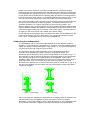
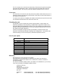
REFERENCE MONITORS
SYSTEM 1200
USER MANUAL
INTRODUCTION
Thank you for purchasing Tannoy System 1200 Monitors.
This loudspeaker is a professional mid-field reference monitor, able to reproduce
with accuracy and at high levels frequencies as low as 40 Hz. Using an advanced 12”
Dual Concentric driver, if offers the advantages of point source operation in a very
cost-effective design. The attractive octagonal shape of the cabinet with its rounded
edge corners and front panel contributes to the excellent acoustic performance of the
cabinet.
Due to its point source operation it will perform equally well in both landscape and
portait orientations.
This manual is intended to provide the user with some useful advice on how to install
and use the loudspeakers, as well as more technical information about how the
system is designed, and its detailed specifications. We hope this will help you to get
the best results from your monitoring system.
OPERATING INSTRUCTIONS
Unpacking and visual checks
To get the speaker out of the carton without damage open the end flaps fully and
bend them right back. Turn the package upside-down on the floor and lift the carton
vertically up to leave the speaker resting on its packing tray.
Inspect each speaker for signs of transit damage. In the unlikely event of this having
occurred inform the carrier and the supplier. Keep all the packaging if damage has
occurred as this will show evidence of excessive handling forces. It is also a good
idea to keep the carton for future transportation.
Preliminary recommendation
Initially we would like to give some words of warning on the high sound levels which
these speakers are capable of generating over sustained periods of time. Levels over
95 dB for 8 hours per day will eventually cause permanent hearing loss. Because
Tannoy Monitors have very low levels of time, amplitude and frequency distortion it
is not always obvious that the sound level is high while working with them.
For continuous exposure we recommend the occasional use of a sound level meter
capable of integrating the sound level over a period of exposure according to noise
control standards. This should be used to check that noise levels are always within
safety limits.
Location and support for the loudspeakers.
When choosing a suitable location for the monitors, bear in mind that the physical
mounting of loudspeakers can have a large influence on performance. For best
results the monitors should be mounted on a rigid structure, supported on pads
making contact with the laminated panel. Self-adhesive foam pads are provided with
the loudspeakers for that purpose. If you intend to arrange the monitors in landscape
format, detach the whole pad from the backing paper and stick it on the large side to
become the bottom of the cabinet ; for portrait arrangement the pad is pre-cut so that
one half can be easily detached to match the smaller size of the bottom panel.
We recommend location of the monitors so that the drive units are toed inwards, with
their axes oriented towards the listening position. The distance between the two
speakers should be 2 to 3 metres, depending on the monitoring position. The
distance between the monitoring position and each speaker should be slightly greater
than the distance between the speakers. If the speakers are placed too close to each
other the full stereo image may not develop, on the other hand if you place them too
far apart you will notice a hole in the middle of the stereo image.
Ensure that the console position does not obscure the direct sound radiation from the
Dual Concentric drive unit when sitting down. The engineer and producer should
have a clear, uninterrupted view of the monitor loudspeakers.
Connecting the loudspeakers.
The loudspeaker can be connected to the amplifier via to two different modes of
operation : conventional wiring and bi-wiring. In the latter mode two separate pairs of
cables are used to connect the amplifier to the monitor, i.e. one for the low-frequency
(LF) and one for the high-frequency (HF) sections.
The termination panels located at the back of the loudspeakers must be set
according to the desired wiring mode, as shown on the figures below. The
termination panels are factory set for normal wiring operation, as shown on Fig.1. In
this mode the LF and HF banana sockets are connected together by two gold-plated
links, allowing a single twin core cable to drive the loudspeaker. For bi-wiring
operation, loosen the banana sockets (turn knob anti-clockwise) and remove the two
gold-plated links ; then connect each twin core cable to one pair of red / black
terminals of the speaker (one is marked LF and the other HF), as shown on Fig. 2. At
the other end (amplifier) the two cables are connected together, positive to positive,
negative to negative.
Figure 1. Normal wiring
Figure 2. Bi-wiring
When connecting the speakers it is essential that consistent polarity is observed. The
red terminal(s) on the loudspeaker must be connected to the red or positive
terminal(s) on the power amplifier, and the black terminal(s) on the loudspeaker must
be connected to the black, negative or ground terminal(s) of the power amplifier.
When operating the loudspeakers in normal wiring mode, it is important that the two
gold-plated links are properly tightened to ensure a perfect electrical connection
between LF and HF terminals.
The types of cable used to connect the speakers to the power amplifier will
marginally affect the sound. The cross-sectional area of the cable should be large
enough so as not to affect the damping factor, and generally a cable with a crosssectional area of 2.5 mm² or greater is recommended.
Before connecting the amplifier and the monitors, it is advisable to ensure that there
is no signal present either by turning amplifiers gain down or by lowering the output
faders.
Power amplifiers.
The power amplifier should be reasonably well matched in power to the rating of the
speakers. A recommended range of power can be found in the specifications (at the
end of this manual). The use of a powerful amplifier (i.e. the higher figure of the
specified power range) provides headroom which is useful especially for highly
dynamic programme materials.
Because of the high peak power handling of the Tannoy monitors, responsible use of
even more powerful amplifiers should not represent a danger for the speakers if the
amplifiers are not overdriven.
SYSTEM DESCRIPTION AND PHILOSOPHY
A loudspeaker design naturally divides into various parts: cabinet, drive unit(s) and
crossover. The design of these parts cannot take place in isolation as they are all
interdependent.
Drive unit.
The drive unit used in the System 1200 monitors is part of the latest generation of
Dual Concentric units designed by Tannoy. Among many others features, this range
of drivers incorporate a dual magnet assembly, ‘tulip’ HF waveguide and injection
moulded polypropylene LF cone.
The design of the HF waveguide has been arrived at by making extensive use of
CAD (computer aided design). It matches the acoustic source impedance at the HF
diaphragm into the acoustic environment, shaping the wavefront as it travels down
from the diaphragm ensuring equal path lengths to achieve a spherical wavefront.
Wavefront shaping begins at the diaphragm surface and, because the compression
ratio can be kept relatively low with this design, the distortions due to air nonlinearities are minimised. A hyperbolic flare has been chosen for optimum low
frequency performance at the crossover point.
The HF diaphragm is made from aluminium and magnesium alloy, with optimised
shape and thickness providing rigid piston behaviour up to 25 kHz. The diaphragm
assembly is suspended by a precision moulded, inert nitrile rubber surround. Its very
narrow roll eliminates resonances below 25 kHz and provides a very stable and
consistent mounting. The roll form ensures high excursions can take place if
necessary yet provides a fatigue-indestructible assembly.
The HF voice coil assembly incorporates a high temperature copper wire chemically
bonded onto a kapton former fitting onto the outside of the HF diaphragm skirt. The
thermal power handling of the voice coil is greatly increased thanks to its ferrofluid
filled magnetic gap.
Physically, the whole HF assembly self centre mounts onto the back of the low
frequency assembly using three screws carrying with it the self-centring HF
diaphragm. Production and field service is therefore virtually foolproof and extremely
consistent.
The LF unit uses a CNC precision injection moulded polypropylene cone, terminated
by a nitrile rubber, high-compliance surround. The characteristic cone termination
impedance is matched by the surround material independently of the required
suspension compliance. The unit system compliance is provided by the rear
suspension where the best degree of mechanical control can be provided.
The shape of the LF cone has been calculated to match the HF hyperbolic
waveguide ensuring the wavefront remains spherical and perpendicular to the cone
surface throughout the propagation.
Purpose-designed trim rings are used to blend the HF wavefront into the cabinet.
This feature has been shown in our research to be the biggest single factor in
providing smooth HF radiation in Dual Concentrics.
The heart of the LF unit is the motor system comprising the magnet and voice coil.
The choice of magnet operating point parameters, air gap flux strength, voice coil
details (number of turns, resistance, winding length, diameter etc.), moving mass,
dynamic compliance and drive unit radiating area presents a very complex
mathematical problem where the solutions can take many different forms. Reaching
the correct answers is much easier if computers can be called on to assist with
solving the equations, as Tannoy do for its drivers.
Cabinet.
Aside the drive units, cabinet design plays a major role in the acoustic performance
of a speaker system. Among the problems which can contribute to the degradation of
the emitted sound field, diffractions and reflections caused by the cabinet boundaries
are too often overlooked although they are the cause of most of the irregularities
heard and measured in the higher frequency areas.
In that respect conventional rectangular, sharp corner boxes perform especially
poorly. On the other hand, the shape of the System 1200 has been designed with
careful attention paid regarding the sculptured front panel to provide smooth,
rounded edges which minimise side diffractions.
Another problem involved in cabinet design is to ensure that the box will effectively
behave as neutrally as possible, ideally without interfering at all with the sound field
emitted by the drive unit and the port. There are two main ways the box can get into
vibration. First there can be a mechanical transfer of energy between the drive unit
and the cabinet front panel. Preventing this requires the use of a rigid and stiff front
baffle, which is achieved on the System 1200 by a very thick and compact MDF
panel. The second way the cabinet can get into vibration is by transmission from
acoustical to mechanical energy. Since high acoustic pressures are present inside
the cabinet this is quite likely to occur if no attention is paid in order to minimise it.
Here the use of rigid panels is also helpful but, since their stiffness cannot be infinite
and therefore their resonances only shifted towards higher frequencies, enough
damping has to be provided in the cabinet assembly, including panels and joints.
Due to its octagonal shape and its cabinet construction, the System 1200 perform
very well in that respect. Its shape tends to decrease the largest dimensions of each
side panel, which reduce low frequency resonances, while the doubled number of
side provides additional damping.
In addition to the cabinet construction the volume and port tuning have been
carefully calculated to give the best set of parameters for monitoring loudspeakers.
There is a fundamental relationship in loudspeakers between efficiency, cabinet
volume and low frequency performance given that minimal amplitude variations can
be tolerated (as in monitoring situations). The set of parameters that are arrived at
as a solution are inevitably a compromise and the skill of Tannoy has always been
shown to be getting these particular parameters correct for the application.
The Sum of the parts.
The crossover is an important, sometimes difficult part of the design. However the
use of an optimised, well designed drive unit makes the task easier and allows using
simpler networks, which generally give better results.
It is also important to point out that a very important benefit of the Dual Concentric
technology is in connection with the crossover. With conventional discrete multidrivers speakers, the crossover has a dramatic effect on the speaker performance in
the frequency range where the different drivers overlap, especially on off-axis
response and on spatial dispersion. Actually, because of the detrimental effects
resulting from the fact that they are non-coincident, the drivers should ideally work in
completely split ranges of frequency. High order low and hi-pass filters are therefore
required to reduce the overlap range. Apart from the fact that it makes the design
more complex, requires more accurate components and increases the costs, a major
drawback is that higher order filters involve increased phase and group delay
distortion, which can be quite perceptible. On the other hand the low order filter used
with Dual Concentric drivers achieve a smooth phase response.
The integration of all the features described above is what makes the whole
loudspeaker system even greater than the sum of the individual parts.
SERVICING
Cabinet finish.
To remove marks and scuffs use a medium soft brush. If necessary, a little warm
water and detergent can be used but under no circumstances use a solvent or
abrasive cleaner. The surface will change colour when wet but will return to normal
when dry. For touch-up of paint chips contact your local Tannoy service agent for
materials and guidance.
Dual Concentric driver removal.
Lay the cabinet on its back. Remove the four hexagonal bolts and set aside. Ease
the driver from the front of the cabinet taking care not to mark the front surface.
Use a piece of stout cardboard to lever against if necessary. Remove the driver, note
the polarity of the internal connections and disconnect the internal wiring. Take care
not to damage the moving parts of the LF driver.
To refit the driver, connect the cables from the crossover to the LF and HF terminals.
Fit the driver into mounting hole, making sure that the internal connecting cables are
not trapped between the HF unit and the cabinet crossbrace. Fasten the bolts finger
tight and then progressively torque them down.
Drive unit servicing.
The HF unit may be fitted with a new diaphragm assembly or replaced as a complete
assembly for speed. In either case, with the driver face down, release the three bolts
securing the HF assembly and lift the HF unit vertically upwards and away from
magnetic attraction caused by the LF magnet. Replace the diaphragm - it is selfcentring - or the complete unit, taking care to align the parts correctly.
To refit the HF unit, hold it about 300 mm vertically above the LF magnet in both
hands while resting on your elbows. Slide your elbows apart and lower the HF unit
onto the back of the LF magnet. As the HF unit gets close to the magnet you will feel
the magnetic fields repelling. Align the fixing holes and secure with the bolts,
tightening down evenly. Do not tighten the bolts finally until you are sure the HF unit
is seated correctly and the two magnet systems appear parallel.
The LF unit may be re-coned in the normal way. Ease the trim ring from the rubber
surround and remember to refit it. The trim ring forms an integral part of the HF
dispersion system. Use only the parts and adhesive supplied in the re-cone kit.
Crossover.
The crossover is mounted on the rear panel of the cabinet, behind the drive unit. To
inspect it, the drive unit has to be removed first. Take care to avoid undue stress on
the cables and components.
To remove the crossover completely the cables must be disconnected from the drive
unit. Please proceed as above to remove the drive unit.
Checking the unit.
The speaker can be checked using a sine wave generator. A high quality, low
distortion (preferably a beat frequency) oscillator will be required to check for any
buzz and rattle noise generated by the drive unit. The voltage to be applied at the
speaker terminals should be about 3V rms (the speakers should be free from buzz
and rattle at any audio frequency).
Checking the speaker at higher levels is permissible, provided that the lower
frequency of the sweep is limited according to the voltage level ; for instance with
levels exceeding 10V rms the frequency should be kept above 100 Hz.
List of spare parts.
PART NUMBER
DESCRIPTION
9900 0314
System 1200 cabinet assembly
7900 0459
Driver kit 3139
7900 0460
Recone kit for LF unit
7900 0199
HF diaphragm assembly
6839 0050
Gasket, 12 inch driver
4504 5725
M5 x 30 cap screw (driver screw)
6184 0009
Port tube
7300 0569
Crossover assembly
4940 0052
Termination panel
6481 0282
System 1200 user manual
6730 0335
Carton System 1200
6460 0073
Moulded badge & label
Warranty
No maintenance of the monitors is necessary.
All components are guaranteed for a period of five years from the date of
manufacture, subject to the absence of, or evidence of, misuse, overload or
accidental damage.
For further information please contact your dealer or the distributor in your country.
If you cannot locate your distributor please contact :
Customer Services
Tannoy Ltd
Rosehall Industrial Estate
Coatbridge, Strathclyde
ML5 4TF
Telephone
Fax
01236 420199 (UK)
01236 428230 (UK)
+44 1236 420199 (International)
+44 1236 428230 (International)
DO NOT SHIP ANY PRODUCT TO TANNOY WITHOUT PREVIOUS
AUTHORISATION.
This warranty in no way affects your statutory rights.
CURVES
Figure 1. On axis anechoic response.
Figure 2. Impedance.
TECHNICAL SPECIFICATIONS
System
Frequency response (1)
40 Hz - 20 kHz
Recommended amplifier power
100 to 350 W rms into 8 Ω
Power handling
Average (2)
180 W rms
Nominal Impedance
8Ω
Sensitivity (3)
95 dB SPL / 1 W @ 1 m
Distortion
< 0.5 %
Dispersion (@ -6dB)
90° conical
Crossover frequency
1300 Hz
Programme
350 W rms
Cabinet
Drive unit
12’’ Tannoy Dual Concentric type 3139
Low frequency design
Optimised bass-reflex load, in 74 litres
Cabinet construction
MDF (36 mm front panel)
Cabinet finish
Spray ‘F’ Vinyl
Cabinet dimensions (HxWxD)
650 mm x 397 mm x 396 mm
Cabinet weight
27 kg
Shipping dimensions (HxWxD)
720 mm x 467 mm x 472 mm
Shipping weight
30 kg
NOTES : (1) +/- 3 dB , measured at 1m in an anechoic chamber.
(2) Long term power handling capacity as defined in EIA standard RS426A.
(3) Averaged over specified bandwith for half-space environment. For anechoic conditions the figure is to be
decreased by 3 dB.
Tannoy operate a policy of continuous research and development. The introduction of new materials or manufacturing
methods will always equal or exceed the published specifications which Tannoy reserve the right to alter without prior
notice. Please verify the latest specifications when dealing with critical applications.
Declaration of Conformity
The following apparatus is/are manufactured in the United Kingdom by Tannoy Ltd
of Rosehall Industrial estate, Coatbridge, Scotland, ML5 4TF and conform(s) to the
protection requirements of the European Electromagnetic Compatibility Standards
and Directives relevant to Domestic Electrical Equipment. The apparatus is
designed and constructed such that electromagnetic disturbances generated do not
exceed levels allowing radio and telecommunications equipment and other
apparatus to operate as intended, and, the apparatus has an adequate level of
intrinsic immunity to electromagnetic disturbance to enable operation as specified
and intended.
Details of the Apparatus:
Tannoy Monitor Loudspeaker
Model Number: System 1200
Associated Technical File:
EMCSYS1200
Applicable Standards:
EN 50081-1 Emission
EN 50082-1 Immunity
Signed:
Position:
Technical Manager
Tannoy Professional
Date:
16th July 1998
For Tannoy Ltd
Tannoy Loudspeakers are manufactured
in Great Britain by :
Tannoy Ltd, Rosehall Industrial Estate, Coatbridge,
Strathclyde, ML5 4TF, SCOTLAND
Telephone: +44 (0)1236 420199 Fax: +44 (0)1236 428230
Internet:http://www.tannoy.com
Tannoy North America Inc. 335 Gage Avenue, Suite 1, Kitchener, Ontario, CANADA, N2M 5E1
Telephone: (519) 745 1158 Fax: (519) 745 2364
Tannoy Nederland BV, Anthonetta Kuijlstraat 19, 3066 GS, Rotterdam THE NETHERLANDS
Telephone: (010) 2860554 Fax: (010) 2860431
Issue 2 Part No. 6481 0282