1
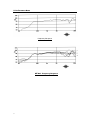
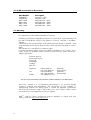
i5 MP
USER MANUAL
Contents
1. Introduction ................................
................................
................................
.......................... 3
............................. 3
2. Unpacking ................................
................................
................................
3. Power Requirements
........... 3
................................
................................
................................
4. Operation ................................
................................
................................
.............................. 4
...... 4
4.1. Connectors/Cabling ................................
................................
................................
........................ 4
4.2. Powering ................................
................................
................................
.......................... 5
4.3. Controls ................................
................................
................................
5. Operation close to TV screens and video monitors
......................... 5
................................
6. Equalisation ................................
................................
................................
.......................... 5
7. Dimensions ................................
................................
................................
........................... 5
8. Hardware ................................
................................
................................
............................... 6
................ 7
9. Performance Data ................................
................................
................................
10. Technical Specifications
... 9
................................
................................
................................
11. IMPORTANT SAFETY INFORMATION
12. i5 MP Service Parts & Accessories
................................
................................
............ 10
................ 11
................................
................................
13. Warranty................................
................................
................................
............................ 11
2
1. Introduction
Thank you for purchasing Tannoy i5 MP.
The Tannoy i5 MP is a powered loudspeaker and has been designed to be both
sonically and cosmetically pleasing for a range of applications from AV presentations
to public address.
TM
ICT or Inductive Coupling Technology offers point source operation, and can h ence
be used in both landscape and vertical positions without affecting the sound quality.
The ICT™ utilises a wireless electromagnetic tweeter that does not require a
crossover and cannot be burned out from heavy or abusive use. The 1" aluminium
high frequency dome has a deep drawn skirt which sits inside the low frequency voice
coil in the same magnetic gap. The skirt is like a single shorted turn, which is induced
with high frequency information generated by the low frequency voice coil, which is
TM
fed a full bandwidth signal. The ICT
dome is at the heart of our i5 MP transducer
which utilises a moulded plastic cone and nitryl rubber surround to further enhance
its' durability and long term reliability.
TM
The ICT driver is housed in a plastic enclosure that has been optimally tuned to
achieve maximum bass response and tonal balance.
For applications requiring extended low frequency enhancement, a range of Tannoy
sub - bass systems are available and can be used in conjunction with the i5 MP.
2. Unpacking
Every Tannoy i5 MP is carefully tested and inspected before packing. After
unpacking, please inspect your i5 MP for any damage sustained during transit. In the
unlikely event of any damage, would you please notify your dealer immediately and
retain your shipping carton, as your dealer may ask you to return the faulty unit for
inspection.
3. Power Requirements
After unpacking check that the voltage rating is correct. The selector can be found
on the rear panel at the back of the speaker, Figure 3a. If the voltage is incorrect,
move the voltage selector to the appropriate voltage. Check that the panel mounted
fuse is also correct for the correct operating voltage , which is located on the same
panel, and can be removed by unscrewing it from the panel. The fuse rating should
match the operating voltage: 500mA/250V for 220
- 240V operation and 1A/125V for
100- 120V operation. The fuse is 5mm ´ 20mm Time Delay, low rupture type. The
fuse should, however, correspond to the set voltage when shipped.
Fuse Holder
Voltage
Selector
Figure 3a
3
4. Operation
4.1. Connectors/Cabling
The i5 MP is supplied with a Phono (RCA) and European Pluggable type connectors,
for both balanced and unbalanced operation. The Phono plug is used for unbalanced
operation, and the European type can be used for both balanced and unbalanced
operation. The unit is powered via an IEC mains socket. See Figure 4a.
When shipped, the unit is set for unbalanced operation. For this, the European type
plug must be connected with pins 1 and 3 linked. Us e shielded single conductor cable
and simply plug a phono connector into the phono socket. Alternatively, if the
European pluggable type plug is used, wire the positive wire to pin 2 and the ground
wire to pin 1 and leave the link in place.
For balanced operation, use twin conductor shielded cable (microphone cable) and
wire the European pluggable type connector as shown in the chart below:
Pin 1
Ground (Screen)
ve
Pin 2 Positive (+ , Red)
ve
Pin 3 Negative -( , Blue)
4.2. Powering
Before connecting th e i5 MP to a mains inlet socket, ensure all other connections are
correctly made. The i5 MP may be supplied with an IEC mains cable. Connect this
cable into the IEC mains socket on the back of the unit. If a cable is not supplied, use
an IEC mains cable wi th the correct plug and rating for your country.
The i5 MP is designed to be powered continuously, but we recommend it is
disconnected from the mains if it is to be left unused for a considerable period of time.
An all pole mains switch with a contact s eparation of at least 3mm shall be
incorporated in the electrical installation of the building.
Mains Input
Voltage
Selector
Phono/RCA
for
unbalanced
operation
European Pluggable
type connector for
balanced/unbalanced
operation
Figure 4a
4
4.3. Controls
The input level volume control is located on the front of the unit. This has been se t to
maximum when shipped. To adjust the level, simply remove the badge and adjust the
gain using a screw driver.
5. Operation close to TV screens and video monitors
As the i5 MP contains a powerful magnet, avoid placing the unit closer than 6" to a
TV s creen or video monitor in order to avoid any picture distortion.
6. Equalisation
The i5 MP is designed to need no equalisation or correction to overcome system
limitations. As a result, it will only need equalisation to compensate for difficult
acoustic environments.
Excess equalisation can reduce system headroom, and introduce phase distortion
resulting in greater problems than it cures. If equalisation is required then it should be
applied gently and smoothly. Violent equalisation will be detrimental to the overall
sound quality. If the loudspeakers were being used consistently at high levels it would
be beneficial to introduce a high- pass filter at 70Hz to protect the loudspeaker from
any unnecessary subsonic frequencies.
7. Dimensions
224mm
8 7/8"
153mm
6 1/8"
163mm
6 3/8"
100-120V / 220-240V~ 50-60Hz 45W
FUSE
110/120V
230V
T500mAL 250V
T1AL 125V
ON
220/240V
INPUT
5
1
2
3
G
+
-
OFF
8. Hardware
The i5 MP can be wall or ceiling mounted using the MB5Y bracket (Figure 8a) or the
MB5B (Figure 8c). Both are designed to offer maximum flexibility in selecting the
desired angles. Methods of mounting have been demonstrated in Figures 8b & 8c.
Figure 8a
Figure 8b
NOTE: The installation of this product
must be carried out in conformity with
local building codes and standards. If
necessary consult your local safety
standards officer before installing any
product. Alternatively, check any laws
or bylaws. Tannoy will not be held
responsible for any damages caused
by the improper installation of any
bracket or loudspeake r.
Figure 8c
6
9. Performance Data
Frequency Response
Off Axis Frequency Response
7
Polar Plots
1 Octave Band Pink Noise
8
10. Technical Specifications
System Type
Multi-Purpose Loudspeaker
Frequency Response +/- 3dB
Maximum SPL
100Hz - 20kHz
105dB (average)
(2)
DI Averaged
@1kHz (ISO)
@2kHz (ISO)
@4kHz (ISO)
@8kHz (ISO)
@16kHz (ISO)
3.9
7.9
8.6
10.3
9.2
Q Averaged
@1kHz (ISO)
@2kHz (ISO)
@4kHz (ISO)
@8kHz (ISO)
@16kHz (ISO)
2.5
6.1
7.2
10.7
8.3
Input Sensitivity
NOTES:
(1)
(for Maximum Input)
108dB
(half-space)
375mV (balanced)
750mV (unbalanced)
Input Impedance
10 kWatt
Power Output
30 Watt
Protection Circuitry
Thermal
Supply
Mains voltage adjustable to 220- 240V or
100-120V AC.
Fuse: 250mV/250V for 220-240V
500mV/125V for 100-120V
Power Consumption
45VA
Driver Complement
1 x 127mm (5”) ICT™ Point Source
Enclosure
4.6 litre polypropylene
Finish
Black or White
Connectors
Balanced, Phoenix™ style 3 terminal in / unbalanced RCA in
Fittings
2 x yoke fixing points
1 x female gimble plate
Dimensions
223.5(H)´ 162.6(W)´ 153.0(D)mm
8.81"(H)´ 6.41"(W)´ 6.03"(D)
Weight
2.9kg (6lbs 5oz)
Accessories
MB5Y and MB5B mounting brackets
Shipping Dimensions
302 x 168 x 168mm
(12 7/8 x 6 3/8 x 6 3/8“)
Shipping Weight
3.1kg (6lbs 15oz)
(1) Average over stated bandwidth. Measure d at 1m on axis, in an anechoic chamber.
(2) Long term power handling capacity as defined in EIA standard RS - 426A.
(3) Unweighted pink noise input, measured at 1m
Tannoy operates a policy of continuous research and development. The introduction of new m aterials or manufacturing methods will
always equal or exceed the published specifications which Tannoy reserve the right to alter without prior notice. Please verify the
latest specifications when dealing with critical applications.
9
11. IMPORTANT SAFETY INFORMATION
·
·
·
·
·
·
·
·
Never expose the unit to moisture, water and extremes of temperature or
humidity. Specifically, the unit must not be exposed to dripping or splashing
and that no objects filled with liquids, such as glasses, shall be placed on the
unit. Do not operate adjacent to a radiator or heater. No naked flame
sources, such as lighted candles, should be placed on the apparatus. The
unit must not be covered by articles such as newspapers, table cloths,
curtains etc.
Never open the unit, as there is a risk of electric shock.
There are no user serviceable parts inside the unit. Always refer servicing to
your Tannoy dealer or authorised service agent.
Avoid violent shocks to the unit during packing or transportation.
Do not plug the unit into the mains until all other connections have been
made and checked.
Due to the powerful magnet within the i5 MP, do not place within 0.5m of a
television or computer monitor, unless your model is provided with magnetic
screening.
If not used for a long period of time, it is recommended that the apparatus is
completely disconnected at the AC mains socket.
This apparatus is designed for use in moderate climates.
A mains cable may be supplied with the product, having a moulded plug at one end
and a moulded mains plug appropriate to the country of use at the other end. Where
the moulded plug is fitted with a mains fuse, always replace with the same type and
rating.
If the fitted plug is unsuitable for your type of outlet sockets, it should be cut off and
disposed of safely, in case it is inserted into a live socket elsewhere. The wires in the
mains cable are coloured in accordance with the following code:
GREEN AND YELLOW
BLUE
BRO WN
EARTH
NEUTRAL
LIVE
AS THE COLOURS OF THE WIRES IN THE MAINS CABLE MAY NOT
CORRESPOND
WITH THE COLOURED MARKINGS IDENTIFYING THE
TERMINALS IN YOUR PLUG, PROCCED AS FOLLOWS:
The wire which is coloured GREEN AND YELLOW must be connected to the
terminal in the plug which is marked either by the letter E, the earth safety symbol
(
), or coloured GREEN or GREEN and YELLOW.
The wire which is coloured BLUE must be connected to the terminal in the plug
which is marked by the letter N or coloured BLACK.
The wire which is coloured BRO WN must connected to the terminal in the plug
which is marked by the letter L or coloured RED.
Ensure the terminals are tightened securely, and no loose strands of wire are
present. Ensure cord grip is clamped over outer sheath of cable, rather than over the
wires.
This equipment has undergone safety and EMC testing, and
complies with the European Law Voltage Directive
and
Electromagnetic Compatibility Directive.
10
12. i5 MP Service Parts & Accessories
Part Number
7900 0567
7900 0749
8001 1680
80011690
8001 1470
8001 1480
Description
Driver Kit - 1273
Amplifier i5 MP
MB 5Y Bracket - Black
MB 5Y Bracket - White
MB 5B Bracket - Black
MB 5B Bracket - White
13. Warranty
No maintenance of the i5 MP loudspeaker is necessary.
All Tannoy professional loudspeaker products are covered by a 5- year warranty from
the date of manufacture subject to the absence of misuse, overload or accidental
damage.
Claims will not be considered if the serial number has been altered or removed. Work
under warranty should only be carried out by a Tannoy Professional dealer or service
agent.
This warranty in no way affects your statutory rights.
For further information please contact your dealer or distributor in your country. If you
cannot locate your distributor please contact Customer Services, Tannoy Ltd at the
address given below.
Customer Services
Professional Division
Tannoy Ltd.
Coatbridge
Scotland
ML5 4TF
Telephone:
Fax:
E - Mail:
01236 420199
+44 1236 420199
01236 428230
+44 1236 428230
[email protected]
(National)
(International)
(National)
(International)
DO NOT SHIP ANY PRODUCT TO TANNOY WITHOUT PREVIOUS AUTHORISATION
Our policy commits us to incorporating improvements to our products through
continuous research and development. The introduction of new materials or
manufacturing methods will always equal or exceed the published specifications
which Tannoy reserve the right to alter without prior notice . Please confirm current
specifications for critical applications with your supplier.
EASETM Data for Tannoy Professional products available on request and from
Tanno ys' web site: http://www.tannoy.com
11
Tannoy Limited, Professional Division, Coatbridge, Strathclyde, ML5 4TF, Scotland.
Tel: +44 (0) 1236 420199 Fax +44 (0) 1236 428230
e-mail: [email protected] Website: www.tannoy.com
Tannoy North America Inc., 335 Gage Avenue, Suite 1, Kitchener, Ontario, Canada N2M 5E1.
Tel: (519) 745-1158 Fax: (519) 745- 2364
e-mail:[email protected] Website: www.tannoy.com
Tannoy Nederland b.v. , Anthonetta Kuijlstraat 19, 3066 GS Rotterdam.
Tel: (010) 286 0554 Fax: (010) 286 0431
e-mail:[email protected] Website: www.tannoy.nl
ML 2
nd
12
October 2003