1
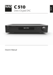
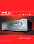
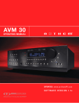
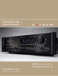
MRX 710 / 510 / 310
Audio/Video Receiver
OPERATING MANUAL
Anthem, AnthemLogic, ARC, and Paradigm are trademarks or registered trademarks of Paradigm Electronics Inc. © Paradigm Electronics Inc.
All rights reserved. The information contained herein may not be reproduced in whole or in part without our express written permission.
We reserve the right to change specifications and/or features without notice as design improvements are incorporated.
Manufactured under license from Dolby Laboratories. Dolby, Pro Logic, and the double-D symbol are trademarks of Dolby Laboratories.
Manufactured under license under U.S. Patent #’s: 5,451,942; 5,956,674; 5,974,380; 5,978,762; 6,226,616; 6,487,535; 7,212,872; 7,333,929;
7,392,195; 7,272,567 & other U.S. and worldwide patents issued & pending. DTS and the Symbol are registered trademarks, & DTS-HD, DTS-HD Master
Audio, and the DTS logos are trademarks of DTS, Inc. Product includes software. © DTS, Inc. All Rights Reserved.
This item incorporates copy protection technology that is protected by U.S. patents and other intellectual property rights of Rovi Corporation.
Reverse engineering and disassembly are prohibited.
HDMI, the HDMI logo and High-Definition Multimedia Interface are trademarks or registered trademarks of HDMI Licensing LLC.
Manufactured under license from QNX Software Systems. © QNX Software Systems. All rights reserved.
All other trademarks are the property of their respective owners.
MRX 710 / 510 / 310
Audio/Video Receiver
OPERATING MANUAL
IMPORTANT SAFETY INSTRUCTIONS
CAUTION
RISK OF ELECTRIC SHOCK DO NOT OPEN
CAUTION: TO REDUCE THE RISK OF ELECTRIC SHOCK, DO NOT REMOVE COVER (OR BACK).
NO USER-SERVICEABLE PARTS INSIDE. REFER SERVICING TO QUALIFIED SERVICE PERSONNEL
The lightning flash with arrowhead
symbol within an equilateral
triangle is intended to alert the user
to the presence of uninsulated
“dangerous voltage” within the
product’s enclosure that may be of
sufficient magnitude to constitute a
risk of electric shock to persons.
The exclamation point within an
equilateral triangle is intended to
alert the user to the presence of
important operating and maintenance
(servicing) instructions in the literature
accompanying the appliance.
1. Read these instructions.
2. Keep these instructions.
3. Heed all warnings.
4. Follow all instructions.
5. Do not use this apparatus near water.
6. Clean only with a dry cloth.
7. Do not block any of the ventilation openings. Install in accordance with the manufacturer’s instructions.
8. Do not install near any heat sources such as radiators, heat registers, stoves or other apparatus (including amplifiers) that produce heat.
9. Do not defeat the safety purpose of the polarized or grounding-type plug. A polarized plug has two blades with one wider than the
other. A grounding-type plug has two blades and a third grounding prong. The wide blade or the third prong is provided for your safety.
When the provided plug does not fit into your outlet, consult an electrician for replacement of the obsolete outlet.
10. Protect the power cord from being walked on or pinched, particularly at plugs, convenience receptacles and the point where
they exit from the apparatus.
11. Only use the attachments/accessories specified by the manufacturer.
12.
Use only with a cart, stand, tripod, bracket or table specified by the manufacturer, or sold with the apparatus.
When a cart is used, use caution when moving the cart/apparatus combination to avoid injury from tip-over.
13. Unplug this apparatus during lightning storms or when unused for long periods of time.
14. Refer all servicing to qualified service personnel. Servicing is required when the apparatus has been damaged in any way, such
as power supply cord or plug is damaged, liquid has been spilled or objects have fallen into the apparatus, the apparatus has
been exposed to rain or moisture, does not operate normally, or has been dropped.
i
WARNING: To reduce the risk of fire or electric shock, do not expose this apparatus to rain or
moisture. Avoid installing this unit where foreign objects may fall onto this unit and/or this unit may
be exposed to liquid dripping or splashing. On the top of this unit, do not place:
• Burning objects (i.e. candles), as they may cause fire, damage to this unit, and/or
personal injury.
• Containers with liquid in them, as they may fall and liquid may cause electrical shock to
the user and/or damage to this unit.
Apparatus shall not be exposed to dripping or splashing and no objects filled with liquids, such as
vases, shall be placed on the apparatus.
Do not install this equipment in a confined space such as a case or similar. Install it away from
direct sunlight, heat sources, vibration, dust, moisture, and/or cold.
Do not cover this unit with a newspaper, tablecloth, curtain, etc. in order not to obstruct heat
radiation. If the temperature inside this unit rises, it may cause fire, damage to this unit, and/or
personal injury.
Install this unit near the AC outlet and where the AC power plug can be reached easily.
This unit is not disconnected from the AC power source when it is turned off. This state is called
the standby mode. In this state, this unit is designed to consume a very small quantity of power.
NOTE: This product is not an auto voltage Receiver. Connect only to the prescribed AC outlet,
i.e., 120V 60Hz or 220-240V 50Hz.
CAUTION: These servicing instructions are for use by qualified service personnel only. To reduce
the risk of electric shock, do not perform any servicing other than that contained in the operating
instructions, unless you are qualified to do so.
CAUTION: Changes or modifications to this equipment not expressly approved by Paradigm
Electronics for compliance could void the user’s authority to operate this equipment.
FCC WARNING: Changes or modifications not expressly approved by the party responsible for
compliance could void the user’s authority to operate the equipment.
This equipment has been tested and found to comply with the limits for a class B digital device,
pursuant to part 15 of the FCC Rules. These limits are designed to provide reasonable protection
against harmful interference in a residential installation. This equipment generates, uses and can
radiate radio frequency energy and, if not installed and used in accordance with the instructions,
may cause harmful interference to radio communications. However, there is no guarantee
that interference will not occur in a particular installation. If this equipment does cause harmful
interference to radio or television reception, which can be determined by turning the equipment
off and on, the user is encouraged to try to correct the interference by one or more of the
following measures:
• Reorient or relocate the receiving antenna.
• Increase the separation between the equipment and receiver.
• Connect the equipment into an outlet on a circuit different from that to which the receiver
is connected.
• Consult the dealer or an experienced radio / TV technician for help.
ii
DO NOT LOCATE IN THE FOLLOWING PLACES:
To ensure long-lasting use, do not locate the unit:
• Exposed to direct sunlight.
• Near sources of heat such as heaters.
Left 0.2 m (8 in)
or more
Above 0.2 m
(8 in) or more
Right 0.2 m
(8 in) or more
• Highly humid or poorly ventilated.
• Dusty.
• Subjected to mechanical vibrations.
MRX 710
ZONE 2
MAIN
• On wobbly, inclined, or otherwise unstable surfaces.
• Near windows where there is a chance of exposure
to rain, etc.
• On top of an amplifier or other component which
dissipates a great deal of heat.
To ensure proper heat radiation, ensure clearance from
walls and other equipment according to diagram.
IMPORTANT INFORMATION FOR UK CUSTOMERS: DO NOT cut off the mains
plug from this equipment. If the plug fitted is not suitable for the power points
in your home or the cable is too short to reach a power point, then obtain an
appropriate safety approved extension lead or consult your dealer. If, nonetheless,
the mains plug is cut off, REMOVE THE FUSE and dispose of the PLUG
immediately, to avoid possible shock hazard by inadvertent connection to the
mains supply. If this product is not provided with a mains plug, or one has to be
fitted, then follow the instructions given below:
IMPORTANT: DO NOT make any connection to the larger terminal which is
marked with the letter “E” or by the safety earth symbol or colored GREEN
or GREEN AND YELLOW.
The wires in the mains lead on this product are colored in accordance with the
following code:
BLUE – NEUTRAL
BROWN – LIVE
As these colors may not correspond with the colored markings identifying the
terminals in your plug, proceed as follows:
The BLUE wire must be connected to the terminal marked with the letter
“N” or colored BLACK.
The BROWN wire must be connected to the terminal marked with the letter
“L” or colored RED.
When replacing the fuse, only a correctly rated and approved type should
be used, and be sure to re-fit the fuse cover. If in doubt consult a competent
electrician.
iii
Behind 0.2 m (8 in) or more
NOTES ON ENVIRONMENTAL PROTECTION
At the end of its useful life, this product must not be disposed of with regular household
waste but must be returned to a collection point for the recycling of electrical and
electronic equipment. The symbol on the product, user’s manual and packaging, point
this out. The materials can be reused in accordance with their markings. Through re-use,
recycling of raw materials or other forms of recycling of old products, you are making
an important contribution to the protection of our environment. Your local administrative
office can advise you of the responsible waste disposal point.
INFORMATION ABOUT COLLECTION AND DISPOSAL OF WASTE BATTERIES
(DIRECTIVE 2006/66/EC OF THE EUROPEAN PARLIAMENT AND THE COUNCIL OF
EUROPEAN UNION) (for European customers only)
Batteries bearing any of these symbols indicate that they should be treated as “separate
collection” and not as municipal waste. It is encouraged that necessary measures are
implemented to maximize the separate collection of waste batteries and to minimize
the disposal of batteries as mixed municipal waste. End-users are exhorted not to
dispose waste batteries as unsorted municipal waste. In order to achieve a high level
of recycling waste batteries, discard waste batteries separately and properly through
an accessible collection point in your vicinity. For more information about collection and
recycling of waste batteries, please contact your local municipality, your waste disposal
service or the point of sale where you purchased the items.
By ensuring compliance and conformance to proper disposal of waste batteries,
potential hazardous effects on human health is prevented and the negative impact of
batteries and waste batteries on the environment is minimized, thus contributing to the
protection, preservation and quality improvement of the environment.
Pb
Hg
Cd
Anthem and any related party assume no liability for the user’s failure to comply with any
requirements.
iv
TABLE OF CONTENTS
INTRODUCTION
Anthem Room Correction
1
1.1
Before Making Connections
33 4.1
Before Starting
1
1.2
In-Use Notices
33 4.2
ARC Software Installation
2
1.3
Front Panel
34 4.3
Microphone Stand Assembly
3
1.4 Rear Panel MRX 710
34 4.4
Microphone Positioning
4
1.5
Rear Panel MRX 310
34 4.5
Measurement
5
1.6
Remote Control
35 4.6
Manual Mode and Targets
6
1.7
Speaker Positioning
36 4.7
Advanced Subwoofer Targets
37 4.8
Printing A Report
CONNECTIONS
37 4.9
Updating ARC
6
2.1
Video Connections
7
2.2
Audio Connections
OPERATION
10 2.3
Antennas
38 5.1
Power On / Off and Volume
10
2.4
Local Area Network
38 5.2
Zone 2 Operation
10 2.5 12 Volt Trigger
39 5.3
Input Selection
10 2.6
39 5.4
Tuner
10 2.7 Power
40 5.5
Level Trim
41 5.6
Bass / Treble / Balance
41 5.7
Lip-Sync
41
5.8
Listening Modes
Dolby Volume and Dynamic Range Control
Infra Red
SETUP
v
13 3.1
HDMI Output Configuration
42 5.9
14 3.2
Speaker Setup
42 5.10 Display Brightness
16 3.3
Bass Managment
42 5.11 Info Display
17 3.4
Listener Position
18 3.5
Level Calibration
19 3.6
Input Setup
43 SPECIFICATIONS
23 3.7
Volumes / Rec Output
44 LIMITED WARRANTY
24 3.8
Network / Remote Control
45 THE BIG PICTURE: FRONT PANEL (MRX 710)
27 3.9
Display
46 THE BIG PICTURE: REAR PANEL (MRX 710)
28 3.10 General Configuration
47 THE BIG PICTURE: REAR PANEL (MRX 310)
30 3.11 Save / Load Settings
31 3.12 System Information
INTRODUCTION
Thank you for purchasing the Anthem MRX series receiver.
The MRX 710, MRX 510, and MRX 310 receivers are cutting-edge home theater audio
components with HDMI switching, video scaling and upconversion, state of the art room
equalization, second zone capabilities, and FM/AM tuner.
Anthem products are engineered to recreate the passion of live performance and thrill of
the best movie theaters by using the highest level of circuit design, proprietary software,
superior build quality, innovative features, and intuitive ergonomics with tremendous
flexibility.
1.1 BEFORE MAKING CONNECTIONS
Check that you have received all items listed below and report discrepancies to
your dealer as soon as possible. In case the unit needs to be transported in the
future, keep the packing materials. Retain the invoice that you received from
your authorized Anthem dealer at time of purchase – without it, service will not be
provided under warranty.
• MRX Receiver
• Remote control
• FM antenna
• AM loop antenna
• 2 AAA batteries
• USB extension cable
• IEC power cord (US / EU / CN types are supplied by factory, other types are
normally provided by the local distributor)
Additional items in Anthem Room Correction kit (ARC-1M):
• USB Microphone
• Microphone clip
• Telescopic stand with boom
• USB cable
• CAT5 cable
• CD containing microphone calibration file and
software installer
1.2 IN-USE NOTICES
• Disconnect the power cord before connecting or disconnecting any components.
• If the receiver was transported or stored in the cold, let it reach room temperature
before use.
• Due to continuing advances, operational characteristics may change. If this
manual contains discrepancies please check www.anthemAV.com for the latest
manual or software.
1
1.3 FRONT PANEL
MRX 710 shown, others are similar. For a larger diagram see inside back cover.
1
2
3
MRX 710
ZONE 2
12
11 10 9
8
1 – Navigation buttons
2 – Display
3 – Volume, level functions, and character selection
4 – Power / standby
5 – Input selection
6 – Zone 2 selection
7 – Level selection
8 – Remote control sensor location
9 – Mode selection
10 – Display brightness
11 – Setup menu selection
12 – HDMI jack (MRX 710/510), headphone jack (behind cover)
2
7
6
5
MAIN
4
1.4 REAR PANEL MRX 710
MRX 710 US model shown. EU model, CN model, and MRX 510 are similar.
1
2
3
4
5
19
18
17
16
15 14 13 12 11 10
9
8
7
6
1 – FM/AM antenna connections
2 – HDMI inputs (HDMI1 accepts up to 4K resolution)
3 – HDMI outputs with Audio Return Channel
4 – AC input
5 – Local area network connection for IP control and Anthem Room Correction
6 – USB jack for software updates
7 – Component video inputs
8 – Composite video input
9 – Coaxial and optical digital audio inputs
10 – Speaker connections
11 – Coaxial and optical digital audio outputs
12 – Zone 2 audio outputs
13 – Record audio outputs
14 – RS-232 interface (bidirectional) for serial control
15 – Analog audio L/R inputs
16 – Main pre-out connections
17 – Trigger output
18 – IR input and output
19 – Chassis ground screw
3
1.5 REAR PANEL MRX 310
US model shown. EU and CN models are similar.
1
2
3
4
19
18
17
16
15 14 13 12 11 10
9
8
7
1 – FM/AM antenna connections
2 – HDMI inputs (HDMI1 accepts up to 4K resolution)
3 – HDMI outputs with Audio Return Channel
4 – AC input
5 – Local area network connection for IP control and Anthem Room Correction
6 – USB jack for software updates
7 – Component video inputs
8 – Composite video input
9 – Coaxial and optical digital audio inputs
10 – Speaker connections
11 – Coaxial and optical digital audio outputs
12 – Zone 2 audio outputs
13 – Record audio outputs
14 – RS-232 interface (bidirectional) for serial control
15 – Analog audio L/R inputs
16 – Main pre-out connections
17 – Trigger output
18 – IR input and output
19 – Chassis ground screw
4
6
5
1.6 REMOTE CONTROL
1 – Main zone power on and standby
2 – Bass, Treble, Balance, Channel Level,
Front panel dimmer
3 – Numeric keypad for tuner presets
1
2
4 – Input list
5 – Tuner preset
6 – Setup menu
7 – Info and status
8 – Navigation controls
9 – Clear for deleting input configurations
and tuner presets, and clearing new entry
10 – Dolby Volume and Dolby Digital Dynamics
3
4
5
11 – Listening mode
12 – Volume
13 – Last menu entry
14 – Mute
6
15 – Next/previous tuner preset, setup menu
page up/down
7
16 – Lip-sync
17 – Backlight
The up/down buttons also control tuner station.
BAL
TREB
LEVEL
1
2
3
4
5
6
7
8
9
PRESET
0
INPUT
i
SETUP
SELECT
8
18 – Zone 2 controls
The left/right buttons also select previous/next input.
DIM
BASS
CL
EA
R
ST
LA
DYN
9
E
MOD
13
10
11
VOL
LIP-SYNC
PG/PR
14
15
12
16
ZONE 2
PR
VOL
VOL
INPUT
17
PR
18
RC-MRX 2
5
1.7 SPEAKER POSITIONING
The illustrations below show typical 5.1 and 7.1-channel speaker placement.
Bass response highly depends on room acoustics and experimentation with subwoofer
placement is recommended. Anthem Room Correction can help with placement.
5.1
Channel
7.1
Channel
6
CONNECTIONS
This section describes connections between system components. Configuration of
input and output will be discussed later, in section 3.
2.1 VIDEO CONNECTIONS
HDMI
With this type of connection, video and audio are carried together digitally.
Maximum video resolution is 4K (also known as UHD and 2160p) at 30 frames per
second for HDMI outputs and HDMI input 1, and 1080p at 60 frames per second for
the rest of the HDMI inputs. Connect HDMI output from MRX to a display with HDMI
input – one with High-bandwidth Digital Content Protection (HDCP) is required to
display copy-protected material. If you are using a 4K source component, connect it
to HDMI input 1. All HDMI connections support 3D.
Be careful when connecting HDMI cables. The connector should easily slide in the
jack – do not insert it on an angle and do not force it. Each connector contains 19
delicate pins and damaged pins can damage jacks. Such damage is not covered
by warranty. If your HDMI cables have been connected enough times that they are
about to wear out, new cables are recommended.
Use only High Speed cables and connecting devices. Connecting devices that
may have worked in an older setup do not necessarily work with Deep Color or
4K. If there is trouble producing an image and the source allows Deep Color to be
disabled, start troubleshooting by turning it off. 12-bit Deep Color that works at
1080p24 may not work at 1080p50 or 1080p60 if cable bandwidth is not adequate
for the higher frame rate.
If you are using adapters or port savers, start troubleshooting by eliminating them.
Use of these devices is generally not recommended.
Component Video
Component video uses three coaxial cables and normally
has a maximum resolution of 1080i, or 480p when the
source is copy-protected with Macrovision.
Composite Video
This traditional standard-definition format combines the black/white and
color information for transmission on a single coaxial cable.
7
2.2 AUDIO CONNECTIONS
AUDIO INPUTS AND OUTPUTS
Digital audio sources can be connected with a coaxial, optical, or HDMI cable. These
carry 2-channel PCM, Dolby Digital, and DTS. The HDMI inputs also accept up to eight
channels of PCM, Dolby Digital TrueHD, DTS-HD, and DTS-HD Master Audio.
Audio on the HDMI outputs is 2-channel PCM as this is meant for the TV’s use.
HDMI AUDIO RETURN CHANNEL
This is meant for use when the TV is the audio source. An example is internet streaming
accessed through the TV’s user interface. As long as the TV also has Audio Return
Channel (check its manual) it sends audio from the TV to the receiver through the HDMI
connection that sends video from the receiver to the TV, eliminating the need for a
separate audio connection. CEC control, described in a later section, must be enabled
for Audio Return Channel to function.
Dialog Normalization
Dolby Digital program material contains non-audio data which the receiver uses to adjust
playback level, when necessary, so volume variations between movies and programs are
eliminated. Without Dialog Normalization, movies not encoded at standardized levels for
the dialog could lose dynamic range – higher levels can result in distorted peaks, lower
levels can result in quiet sounds disappearing into the noise floor.
If the display reads “Dial Norm Offset -4.0 dB” at the start of a movie, it is indicating that
the encoded level is higher than standard by 4.0 dB – the playback level of all channels is
then automatically reduced by 4 dB.
Preamp outputs
The pre-outs are variable according to the volume control and can be used with external
amplification.
Zone 2 and REC
Zone 2 and REC may use analog input, or the optical/coaxial inputs as long as the
source is 2-channel PCM.
If HDMI audio from a Dolby
Digital, DTS, or 2-channel PCM
source is problematic or takes
too long to switch, use of coax/
optical audio connection is
recommended (HDMI video can
still be used). Older cable and
satellite receivers often benefit
from this.
The coax and optical REC
outputs provide a passthrough
of coax/optical input, or
2-channel PCM, depending on
source format.
8
SPEAKERS
Connect using speaker wire. US models also allow banana plugs.
MRX 710 and MRX 510: If you are only using 5.1 speakers in the main zone, the two
remaining amp channels may be configured for use in Zone 2, or to bi-amp front L/R
in the main zone.
Connect the positive (+) connection on the speaker
to the positive (+) binding post on the appropriate
amplifier output, and the negative (–) connection on the
speaker to the negative (–) binding post on the same
receiver channel using cable that is insulated to handle
the maximum output of the receiver. Carefully remove
insulation using a wire stripper.
If using speaker cables with banana connectors, first turn the binding post until it is
closed. This way, the plug can be fully inserted.
Do not connect more than
one speaker to each amplifier
output. Be sure that power is
turned off when connecting or
disconnecting anything and
that the speakers are rated for
use with this receiver.
+
–
9
2.3 ANTENNAS
To connect the AM loop antenna, press the spring-loaded tabs of the AM
ANTENNA connector and insert the bare ends of the two wires. Move the
antenna until best reception is found.
For the FM antenna, use the FM ANTENNA connector. Later, when unit is
operating move the antenna to find best reception.
2.4
LOCAL AREA NETWORK
This connection is required for configuring Anthem Room Correction and
for using IP control. Connect your router using CAT5 cable or a wireless
bridge. In the absence of a network or Ethernet router, ARC may also
be used with direct CAT5 connection to personal computer although this
requires configuring a static IP address.
2.5
12 VOLT TRIGGER
If another system component has a trigger input it can be activated by
the receiver. Connect the receiver’s trigger output using a cable with
3.5mm mini plugs. The receiver provides flexible trigger options. Through
the setup menu, you can specify the conditions for enabling triggers.
2.6
INFRA RED
An external IR receiver allows the remote control to be used from another
location in your home – connect the receiver from an external IR hub to the IR
IN jack. Most standard IR repeater kits can be used but to avoid problems test
compatibility before installing permanently.
IR OUT is provided for convenience. Through an IR emitter, commands
coming in through the rear panel IR IN can be re-transmitted to the IR sensor of
another component in your system.
2.7
POWER
Connect the power cord to the receiver and the
power source.
10
EXAMPLE 1
HDMI IN
WAN
LAN
HDMI IN
2
1
3
WAN
4
LAN
1
2
3
4
HDMI OUT
HDMI OUT
11
SETUP
For optimum performance and enjoyment, your receiver should be properly set up.
This may appear like a lot of work but most settings do not need to be changed
from defaults. The important ones relate to your display and input connections,
and distance from listening area to each speaker. Anthem Room Correction will set
crossovers and channel levels. The rest is preference and the listening mode presets,
for example, should be set after you have played various sources and determined
which surround modes you like most.
Front Panel
Remote
INPUT
SETUP
SELECT
CL
EA
R
ST
LA
PG/PR
HOW TO NAVIGATE IN THE SETUP MENU
• Press Setup to enter or exit
• Use the up/down/left/right buttons to move through menus and selections
• Press PG/PR up/down to skip page
• Press Select to make a selection or to start/finish editing the item
• Pressing Last while editing returns the item to its previous setting
• Press Clear to set the item to its default value
The menu below appears on your display once pressing Setup. If it does not appear,
make compatible selections in the HDMI Output Configuration menu while using the
front panel display which shows similar information, one item at a time. On-screen,
up to nine menu items are displayed at once although for clarity this manual shows
all items in each menu together.
Main Menu
HDMI Output Configuration
Speaker Setup
Bass Management
Listener Position
Level Calibration
Input Setup
Volumes / REC Output
Network / Remote Control
Display
General Configuration
Save / Load Settings
System Information
12
3.1 HDMI OUTPUT CONFIGURATION
Highlighting HDMI Output Configuration in the main menu then pressing Select displays
this menu:
HDMI Output Configuration
HDMI 1 Color DepthAuto
HDMI 2 Color DepthAuto
Video OutputAuto
Video Scaling
Processed
On-Screen Info Display On
HDMI Color Depth
With the default Auto setting, color depth is set to the highest capability reported by the
display’s HDMI connection. The 12 and 10 bit formats are known as Deep Color and these
will be used if compatible. If there is no picture due to insufficient bandwidth in the HDMI
cabling, and replacing it is not practical, changing Auto to 8 bit should help.
Video Output
The default is Auto, in which both HDMI outputs are active and the highest resolution that
both displays support is used. If the setting is changed to HDMI1 or HDMI2, video output
resolution will be according to the display connected to the respective port.
Video Scaling
The default is Processed in which video inputs are deinterlaced and scaled according to
the highest resolution supported by the display. With the Passthrough setting, inputs are
switched to the output without processing.
On-Screen Info Display
When changing volume, input, listening mode, etc, the info that is shown on the front panel
is also shown on-screen for 5 seconds. To disable the on-screen info, turn this setting Off.
13
3.2 SPEAKER SETUP
If your source components also have bass management and time alignment, be sure
to disable them by setting all channels “large” and to the same distance from listener
since the receiver will be performing these tasks. Audio quality will be degraded if these
processes are performed twice.
Speaker Setup
Config 1
Config 2
Back Amp
Main Back
Two configurations
One speaker configuration is normally suitable but two sets of bass management, listening
position, level calibration, and ARC equalization values can be entered and stored. This can
be useful if your installation varies according to sound-altering characteristics such as screen
up vs down, door open vs closed, or with subwoofer vs without.
Back Amp (MRX 710/510)
This assigns how the sixth and seventh amplifier channels will be used. Main Back is the
default and is meant for use with 7.1 speakers in the main zone.
Select Zone 2 if using up to 5.1 speakers in the main zone and 2 speakers in Zone 2.
Main Front Biamp setting
This can be useful with up to 5.1 speakers in the main zone and no speakers in Zone 2
if the front Left/Right ones allow biamping (not to be confused with biwiring, where two
sets of cables are used by one amplifier channel). Bi-amplification is where two amplifier
channels are connected to one speaker, with one powering the speaker’s woofer section
and the other the mid/tweeter section. Speakers that allow this have two sets of connection
terminals. The jumpers between the terminal pairs must be removed before the system is
connected, otherwise permanent damage to the amplifier may result.
Keep in mind that best practice is to use amplification with enough power for the application
and that the purpose of biamping is to get the most out of existing equipment should a
situation arise where the amplifier may be at its output limit. If one channel is doing so, the
other speaker section, still operating within its limit, is immune from distortion generated by
the overworked section. By contrast, in a conventional setup with one amplifier channel
amplifying the entire range, the distortion that may result, for example, from excessive bass,
can affect the entire frequency range through the midrange driver and tweeter instead of
being confined to the woofer.
Common misconceptions are that the purpose of this configuration is to increase maximum
output, and that the speaker’s passive crossover is subject to excess levels of unneeded
frequencies, thus wasting the amplifier’s power. In reality, power delivery outside of the
section’s frequency range is negligible due to its rising impedance (no wasted power), and
the total power delivery across both speaker sections is no different than in the conventional
setup (no power increase).
14
Speaker Setup
Profile Name
Config 1
Center On
SurroundsOn
BacksOn
SubwooferOn
Profile Name
Using the navigation keys and volume knob each profile can be renamed, up to 8 characters
long. When finished, press Select but note that the profile name is best set in Anthem Room
Correction (Targets panel) because during file upload the name in the menu is overwritten by
the one in ARC.
Center / Surrounds / Backs / Subwoofer
If using Anthem Room Correction, these items will be set during measurement. Set to “On”
if you are using these speakers, “Off” if you are not. This is an important step so no sounds
go missing because by setting unavailable channels to “Off”, the sound that would have
come from those speakers is rerouted to available speakers.
“Off” setting for
• Center – the center channel plays from the L/R fronts.
• Surround – the Surround-L channel plays from the Front-L channel and the Surround-R
channel plays from the Front-R channel (except Dolby Pro Logic modes).
• Backs – the Back-L channel plays from the Surround-L channel and the Back-R channel
plays from the Surround-R channel.
• Subwoofer – the subwoofer plays two things, LFE (Low Frequency Effects) channel in
multichannel soundtracks and bass from remaining channels using the crossover.
Some people prefer to play music through a system that does not use a subwoofer though
it should be noted that the reason often cited is that the subwoofer does not blend well
with the main speakers. In contrast, Anthem Room Correction excels in integrating the
subwoofer with the main speakers, so in this case using a subwoofer is recommended for all
sources. The subwoofer normally plays bass that is louder, deeper, and less distorted than
that of a full-range speaker, and it uses its own amplifier.
15
3.3 BASS MANAGEMENT
In this menu, information about your speakers is used so that bass does not
become distorted. If using Anthem Room Correction, these items will be set during
measurement, so you may skip this menu.
If your subwoofer has a crossover, it should be bypassed – set its frequency control to
the highest frequency.
The bass manager is a crossover that divides audio in two frequency bands suitable
for subwoofer/satellite speaker systems. The result is a lower bass level for satellite
speakers, and no midrange/treble going to the subwoofer.
Highlighting Bass Management then pressing Select displays this menu:
Bass Management
Config 1
Config 2
Two configurations may be set up. Each contains the following:
Bass Management
Front Crossover
Center Crossover
Surround Crossover
Back Crossover
Subwoofer LPF for LFE
80 Hz
80 Hz
80 Hz
80 Hz
120 Hz
Crossover Frequency
The range is 40 to 160 Hz in 10 Hz steps, or Off which bypasses the crossover. Note that
a crossover does not cut frequencies off like a cliff, but rolls them off according to a slope.
If set to 80 Hz, for example, frequencies lower than 80 Hz are still played. Setting the
crossover to the lowest number on your speaker’s specification page is unlikely to provide
the best result.
16
3.4 LISTENER POSITION
Through these settings, sound coming from all speakers is coordinated to reach the
listening area at the same time. This way, proper imaging is achieved. The channel with
the greatest distance setting will have no delay while channels with shorter distance
settings will be delayed accordingly.
Distances may be set before or after running ARC (ARC does not set distances).
Listener Position
Unitsfeet
Config 1
Config 2
For measurement units, select feet or metres.
These settings are displayed for each configuration:
Listener Position
Front Left
Center
Front Right
Surround Right
Back Right
Back Left
Surround Left
Subwoofer
12 feet
12 feet
12 feet
12 feet
12 feet
12 feet
12 feet
12 feet
Enter the distance between your primary listening area and each speaker. Range is
0-30 ft in 1 ft increments or 0-9 m in 0.3 m increments.
17
3.5 LEVEL CALIBRATION
Level Calibration uses internally generated test noises to match speaker output levels
at the listening position. These noises are also a way of checking system connections
between receiver, amplifier, and speaker. Audio calibrations from home theater setup
discs are not recommended – some use incorrect methods.
If using Anthem Room Correction, these items will be set during measurement.
A sound pressure level (SPL) meter with C-weighting is recommended if not using ARC,
especially to set the subwoofer level. Measure the sound pressure from the listening
position while pointing the meter up. Hold it away from your body to prevent reflections.
Level Calibration
Config 1
Config 2
These settings are displayed for each configuration:
Level Calibration
Test Noise
Dolby Offset / Calibration Level
Front Left
Center
Front Right
Surround Right
Back Right
Back Left
Surround Left
Subwoofer
Off
0 dB
0 dB
0 dB
0 dB
0 dB
0 dB
0 dB
0 dB
0 dB
Test Noise
To play the test noise, select “On”. Use the up/down buttons to move the noise to the other
speakers.
Dolby Offset / Calibration Level
This is the master volume for this menu’s test noises. Changing it changes the output of all
channels. The noise comes out of the left front channel.
Channel level
If you’re calibrating by ear, use the remote control and sit in the listening area. Adjust each
channel’s loudness until all levels sound the same. If using an SPL meter, adjust level so it
reads 75 dB for each channel. If Noise Level is set while Front-L is at 0 dB, no adjustment
of Front-L is needed since the output is the same. If using a powered subwoofer, make a
rough adjustment with its input level control before setting sub level in this menu or using
ARC. Speakers set to “Off: in the Bass Management menu are skipped.
18
Multiple Subwoofers
If using multiple subwoofers they
must be balanced to one another
before further audio setup,
including when using ARC. Play
the subwoofer test noise with
only one subwoofer connected at
a time. Set its input level dial so
the SPL meter reads 71 dB from
the listening area if using two
subs, or 67 dB if using four subs.
Repeat this for the remaining
subs. When all are connected
the result should be around 75
dB. ARC sets the final level. If not
using ARC, change the level of
all subs equally for a combined
result of 75 dB SPL.
To fine-tune the level or phase of
each sub relative to one another,
listen to FM “shhhh” noise
through the subwoofers only (turn
off main amplifiers), and adjust
(or better yet have someone else
adjust) the sub’s level and/or
phase control until bass is loudest
in the listening area.
3.6 INPUT SETUP
Inputs and listening mode presets are configured in this section. From the factory, 5
inputs are set but you may change this to anything from 1 to 20 configurations.
Input Setup
HDMI 1
HDMI 2
HDMI 3
FM
AM
Add Input
To add an input at the end of the list, highlight Add Input and press Select.
To insert an input, highlight one on the list and press Input. The new input will be
inserted after the highlighted one.
To delete an input, highlight it and press Clear on the remote control.
These settings are displayed for each configuration:
HDMI 1 Setup
Input Name
Video Input
Audio Input
Zone 2 Input
Process Analog Audio Input
Speaker Profile
Anthem Room Correction Dolby Volume
Dolby Volume Leveler
Listening Mode for 2.0 Sources
Listening Mode for 5.1 Sources
Lip Sync
HDMI 1
HDMI 1
HDMI
Analog 1
N/A
Config 1
N/A
Off
5
Last Used
Last Used
0 ms
19
Input Name
Using the navigation keys and volume knob each input can be renamed, up to 8 characters
long. When finished, press Select.
Example – Rename “HDMI 1” to “Blu-ray”:
• Highlight “Input Name” and press Select. The first character will be highlighted in red.
• Use the up/down buttons or volume knob to change “H” to “B”.
• Use the left/right buttons to move to each remaining character and complete the
renaming.
• Press Select to return to the menu
Video Input
Select the connection to be used – HDMI1-7, Front HDMI (MRX 710/510), Component 1-2,
Composite, None.
Audio Input
Select the connection to be used – HDMI, HDMI Audio Return 1-2, Coaxial 1-2, Optical 1-3,
Analog 1-5, AM Radio, FM Radio, None.
Zone 2 Input
Select the connection to be used – Coaxial 1-2, Optical 1-3, Analog 1-5, AM Radio, FM
Radio, None. Note that with coaxial and optical input, the source must be 2-channel PCM.
Process Analog Audio Input
If changed to No, digital conversion and signal processing are bypassed. Only level
adjustments will be available.
Speaker Profile
Select the profile to use with this input.
Anthem Room Correction
The ARC measurement process, described later, will turn this on. To disable room
equalization afterward, change this to “Off”. If measurement info isn’t loaded, “N/A” is
displayed.
Dolby Volume (MAIN only)
Select On or Off. Dolby Volume makes content with large differences in volume easier to
listen to by analyzing it and intelligently adjusting two things – level and frequency response.
It does this continually without causing pumping and breathing artifacts that are common
with traditional dynamic range compressors. In doing so, the volume setting is taken into
account as is our hearing’s declining sensitivity to the lowest and highest frequencies relative
to the midrange as their levels drop. The result is that the perceived frequency response
remains constant while making quieter parts of the content more listenable.
Dolby Volume Leveler
This applies when Dolby Volume is turned on. The leveling amount can be set from 1 to
9, or Off. Play various sources to find your preferred setting. When Leveler is “Off” the
frequency response adjustment still applies.
20
Listening Mode Presets
A listening mode is processing that enhances source material by increasing the number of
output channels. Each mode performs this its own way, providing its own type of sound.
To find your preference, spend some time listening to various modes using various sources.
To disable presets and make selections entirely on the fly, select “Last Used”. To disable
listening modes altogether, select “None”.
Modes fall in two main categories – those that apply to 2-channel sources and those that
apply to 5.1-channel sources.
For 2.0-channel sources
AnthemLogic-Cinema provides the missing link that lets you experience full impact home
theater sound from any 2-channel source. A large, enveloping and dynamic listening
experience is created making 2-channel movies sound more like what is experienced in a
state-of-the art movie theater. Through extensive listening tests a very effective design was
developed, avoiding the use of echo effects which could negatively affect the purity of the
sound.
AnthemLogic-Music enhances the stereo listening experience without detracting from the
stereo soundstage. This is also a minimalist design that uses no echo or reverberation
effects. To ensure that the purity of the stereo music soundstage is in no compromised
when you’re sitting in the “sweet spot” and listening to your favorite stereo recordings, the
center channel is not used.
Dolby Pro Logic IIx Movie is the decoder created for 2-channel movies and TV programs
encoded in Dolby Surround.
Dolby Pro Logic IIx Music can be used with stereo music to make it more compelling. When
engaged during playback, these adjustments are accessible by pressing the Mode button:
- Center Width is adjustable from 0 to 7. Setting this to 0 places all center sound in the
center speaker while 7 places it equally in the left and right channels. The default is 3.
- Dimension has seven steps of balance adjustment between the surround and center
channels.
- Panorama when “On” extends the front stereo image to include the surround
channels. This is effective for recordings that have strong left or right channel
elements.
DTS Neo:6 Cinema is a matrix decoder that can be used with any matrix-encoded movie.
Separation is created by allowing sounds to be placed at different points in the sound field.
DTS Neo:6 Music is a matrix decoder for stereo music.
All Channels sends the left and right channels to the surround and rear channels with equal
loudness while the center channel and subwoofer receive a combination of both.
21
For 5.1-channel sources (MRX 710/510)
7.1 speakers are needed in the main zone.
Dolby Pro Logic IIx Movie is suitable for extracting back channels from any 5.1-channel
source.
Dolby Pro Logic IIx Music is similar but with increased emphasis on the surround channels.
DTS Neo:6 is also suitable for extracting back channels from any 5.1-channel source.
Lip-Sync Delay
If audio is heard before its corresponding image is seen, you can set up to 150 milliseconds
of audio delay – set using synchronization test disc or trial and error. Movies are not always
the best test because sounds including dialog are usually re-recorded after the filming is
completed, and can be slightly out of sync at various points in the recording. Adjustment
can also be made while viewing material after pressing the Lip-Sync button.
22
3.7 VOLUMES / REC OUTPUT
Here you can set preferences as listed.
Volumes / REC Output
Mute Level
Main Max Volume
Zone 2 Max Volume
Main Power On Volume
Zone 2 Power On Volume
Mute Analog REC Out when selecting
Mute Digital REC Out when selecting
Silent
10 dB
10 dB
-35 dB
-35 dB
Never
Never
Mute Level
When Mute is pressed, sound can cut out completely or decrease in volume by the
amount that you set to keep some of it in the background. Select from Silent or -5 to
-30 dB in 5 dB steps.
Maximum Volume
These settings allow you to limit the volume setting to avoid damaging equipment and/
or hearing.
Power-On Volume
The volume will be at these levels when the receiver is turned on.
Recording Device
If using a recording device, select the input that the recorder’s output is connected to.
This prevents the recorder’s output from being fed back to its input, something that
results in a loud noise.
23
3.8 NETWORK / REMOTE CONTROL
Network / Remote Control
Device Name
Network Type
IP Configuration
Trigger Configuration
TCP Port
UDP Port
Rear IR
Front IR
Tx Status
MRX 710
Wired LAN
14999
14999
Enable
Enable
Disable
Device Name:
This is the name that the receiver broadcasts, and it can be changed using up to 16
characters.
Network Type:
The default is wired LAN, which will allow the easiest way to run Anthem Room
Correction, described later, as long as the receiver is connected to an Ethernet router.
The alternative is to change the setting to Direct Connect (generally not recommended),
which allows connecting the CAT5 cable directly between the receiver and your
computer, but your computer will need to have its network settings changed to make
this work. Setting a static IP address is beyond the scope of this manual because
the method varies according to the computer’s operating system. Instructions may
be found on the Internet by entering “How to assign a static IP address” into a search
engine.
Once you have located a screen resembling the one below, enter these settings:
IP address: 192.168.1.2
Subnet mask: 255.255.255.0
Default gateway: 192.168.1.1
Normally, you should return
the setting to “Obtain an IP
address automatically” when
the static address is no longer
needed.
24
IP Configuration
Settings in this submenu should only be changed if your network administrator gives the
direction or if using Direct Connect to run ARC.
IP Configuration
ModeAuto
IP192.168.1.3
Subnet Mask
255.255.255.0
Gateway192.168.1.1
Mode
Static IP settings take effect once this is changed to Manual. For ARC, enter the IP,
Subnet Mask, and Gateway values shown above (note that the receiver’s IP address is
not the same as the computer’s).
Trigger Configuration
When the receiver’s trigger output is connected to the trigger input of another
component, such as an amplifier or projector, the receiver can turn it on or off according
to the trigger’s setup.
Trigger Configuration
Trigger Control
Menu
Main or Zone 2
Power
HDMI 1
Off
HDMI 2
Off
HDMI 3
Off
FMOff
AMOff
In the example shown, the trigger activates while Main or Zone 2 power is turned on.
Trigger outputs can also be set to activate according to any combination of inputs
instead of Power.
If triggers are to be controlled through IP or RS-232, change “Menu” to “RS-232/IP”.
25
TCP and UDP Port
Change these only if there is a conflict with another application that uses 14999.
Rear and Front IR
This allows you to disable each of the receiver’s infra-red inputs, which can be useful
when the receiver is connected to an IR repeater and is receiving too many signals.
Note that the moment that you disable the front IR input, you will not be able to control
the receiver the traditional way from the remote control – re-enable the IR input using
the front panel buttons. If your remote control appears to not be working and you have
checked the batteries, check this menu next before contacting technical support.
Tx Status
When enabled, all commands, status changes, and control information are reported
through the Ethernet and RS-232 connections.
26
3.9 DISPLAY
The front panel display’s brightness is set here.
Display
BrightnessMedium
Wake Up Brightness
Up 1
Brightness:
Set preferred default brightness.
Wake Up Brightness:
When a button is pressed the display can go to a brighter level for 5 seconds – select
None, Up 1 brightness level, Medium, or High. When “None” is selected and the display
is off, the wake-up behaves as Up 1 to indicate that the unit is running.
27
3.10 GENERAL CONFIGURATION
This menu contains power saving, control, and tuner options.
General Configuration
Auto Off
ECO Mode
IP Control
Standby IP Control
Standby HDMI Bypass
CEC Control
CEC Power Off Control
CEC Power On Control
AM Tuner Steps
FM Tuner Steps
30 minutes
Enable
Enable
Disable
Disable
Off
Disable
Disable
10 kHz
100 kHz
Auto Off
When there is no input signal the receiver will turn off after the selected time: 5, 10, or
30 minutes, 1, 2, or 6 hours, or Never.
ECO mode
When enabled, options that increase power consumption during standby are disabled.
With default settings, just under 0.3 W is consumed in standby.
IP Control
With this setting you can enable/disable response to networked Internet Protocol
commands.
Standby IP Control
By default, the receiver goes into a low-consumption standby mode and does not
sense IP commands while in it. To make it respond to a power-on command, enable
this setting. Standby consumption increases to 2.0 W (1.8 W if network cable is not
connected).
Standby HDMI Bypass
This option brings standby consumption to 5.6 W (6.6 W if Standby IP Control is also
in use) although it allows use of an HDMI source without turning on the receiver. Select
HDMI 1-7, Front HDMI (MRX 710/510), or Last Used. The standby LED on the front
panel changes to red. Your TV may need setup to allow the sound to come from its
speakers – check its manual.
28
CEC
When Consumer Electronics Control is enabled it allows controlling one HDMIconnected component using another’s remote control, as long as CEC is also enabled
in the other components. Note that when component brands are mixed this control
system may not be reliable.
CEC Control must also be On for Audio Return Channel, described in an earlier section,
to function.
After changing CEC settings or
loading factory defaults it may be
necessary to briefly disconnect
and reconnect the HDMI cable
between the receiver and TV or
source component for the new
settings to be recognized.
With CEC, turning on one component in the system can turn on the rest of the system,
same with turning one component off. You may or may not want this which is why
separate options are provided for Power Off and Power On control. When either
is disabled, the corresponding power commands sent by other HDMI-connected
components are ignored. This is also useful if you would like to use Audio Return
Channel but not one-touch power.
Tuner Steps
Set according to your country’s radio standards.
AM step can be set to 9 kHz (range 531-1710 kHz) or 10 kHz (range 530-1710 kHz).
FM step can be set to 50 or 100 kHz (range 87.50-108.00 MHz), or 200 kHz (range
87.5-107.9 MHz).
29
3.11 SAVE / LOAD SETTINGS
Save / Load Settings
Save User Settings
Load User Settings
Reset on-the-fly Settings
Load Factory Defaults
Save/Load User Settings
After selecting Save User Settings and confirming, all menu settings will be stored. If
you change settings later and want to recall the saved settings, select Load User
Settings and confirm.
Reset on-the-fly Settings
After selecting and confirming, all non-menu settings such as level and bass/treble will
be reset.
Load Factory Defaults
After selecting and confirming, all menu settings will be reset.
Master Reset
This is not a menu setting. To reset the unit to factory condition, connect power and
press the front panel Setup and main power buttons at the same time. The unit should
turn on. This may be useful if unit has become inoperable.
30
3.12 SYSTEM INFORMATION
System Information
Update Via USB
Release Version
Main Micro Version
DSP Version
HDMI Version
ARC Name
ARC Upload Time
MAC Address
LAN Status
1.0.5
1.0.5
0.2.2
0.2.1
7C:B7:7B:00:00:0A
Disconnected
Update Via USB and Version Numbering:
The operational characteristics of the receiver are controlled by software installed
through the USB port on the rear panel. Updates can be downloaded from our web site
and installed afterwards.
• On www.anthemAV.com locate the software pertaining to your MRX model and
voltage. Proceed only if your version is a lower number, indicating that it is older.
• You will be asked where to save a .zip file – save it to Desktop.
• When the .zip file download is complete, extract it to Desktop.
• See Read Me.txt for the change history.
• Copy the .fw file to your USB flash drive, root directory (not in a folder). Make sure
that no other .fw file is in the root directory.
• Connect the USB flash drive to the back of the receiver, directly or through the
supplied USB extension cable.
• Select Update Via USB. Alternatively, the front panel Select button can be pressed
for 8 seconds to start the process without going into the setup menu (MRX must be
powered on first). Installation takes less than 10 minutes and the front panel display
will indicate progress. Do not interfere by pressing buttons or turning power off – the
unit will turn on and off by itself a few times. At the end it will remain on with the
normal source and volume info on the display.
ARC Name
This is the name that you gave to your measurement file.
ARC Upload Time
This is the date and time that your ARC file was uploaded.
MAC Address
This is your receiver’s unique identifier on the network.
LAN Status
This displays the receiver’s IP address once connected to the local area network.
31
ANTHEM ROOM CORRECTION
ARC corrects the effects of reflective surfaces and room boundaries on sound quality
by measuring the response of each speaker relative to the listening area and equalizing
it. ARC equalizes response without stressing the amplifier or speakers and does not
downsample the source material to process it. ARC’s filters are neither graphic nor
parametric – ARC is a sophisticated system that flattens response using its ability to
create practically any suitable function, inherently correcting phase effects created by the
room.
The default correction range is up to 5 kHz. Although the limit can be changed if
needed, a higher one is generally not advised since the microphone becomes directional
at upper frequencies, affecting measurement accuracy especially if the height of the
speaker’s high frequency driver is not at ear level.
ARC also detects how much the room reinforces low frequencies due to its boundaries
and pressurization. This room gain shows as a bump in the target response. ARC does
not remove it because if flattened, bass sounds thin. Ideal anechoic speaker response,
a straight line as measured in a special non-reverberant facility, is not the same as ideal
in-room response which normally includes, to varying degree, this room gain.
ARC senses where each speaker’s low-frequency response declines and sets high-pass
filters accordingly. Calibration is set such that average level is the same when comparing
EQ “On” vs “Off”. Note that to set levels ARC uses a midrange band that’s wider than
the standard home theater setup noise, which is centered at 1 kHz and narrow so
there’s no chance its level would be reduced by a crossover.
Sample response:
EQ is also available for
my subwoofer(s) – should
I use it?
Since rooms and correction
systems, the answer varies
although it is best to disable the
subwoofer’s EQ before running
ARC. If the resulting calculated
and target curves resemble each
other, there is usually no reason
to use the sub’s EQ. If the curves
significantly differ through a wide
range, enable the sub’s EQ and run
ARC again to see if it helps. If you
have run ARC with the sub’s EQ
enabled, ARC must be run again
once the sub’s EQ is turned off.
Multiple Paradigm subs with PBK:
Results are often better with PBK
run on each sub before using ARC.
32
4.1 Before starting
• Ensure that the receiver software and ARC-2 software that you will be using are
compatible with one another – check www.anthemAV.com for latest versions.
• Your ARC microphone and its support file are a system. Before a mic can be used
for measurement, its response must be known. Each ARC microphone’s frequency
response is measured precisely at the factory and this is used to create your
microphone’s calibration file.
• Your computer must be running Windows Vista or later and be connected to a
local network. If a router is not available, the computer may be connected directly
to the receiver using a static IP address as explained in the setup menu section of
this manual. Windows XP also runs ARC-2 but this is not supported in itself due to
the age of the operating system. If an issue presents itself in this case, the solution
would be to use a newer version of Windows.
• If you are using a laptop computer, check its power settings and battery meter to
ensure that procedures will not be interrupted.
• The measurement process rejects typical background noise but if loud noise is
present ARC will indicate that re-measurement is required. Ensure that the room will
be sufficiently quiet during measurement.
• Depending on how your network is set up, you may need to enable sharing to allow
the receiver to be seen by your computer.
• If you are using more than one receiver on the network, note that each may be
identified three ways – by MAC address, IP address, or Device Name (for more
information see the System Information and Network setup menus).
4.2 ARC SOFTWARE INSTALLATION
Instructions will appear on your computer’s screen once the ARC CD is read. If your
computer does not allow a CD to auto-run then double-click on the My Computer icon that’s
on Desktop, select the drive that the CD is in to view its contents (you may need to rightclick on its icon then select Explore), and double-click on setup.exe.
If you downloaded ARC from our web site it needs to be extracted before setup is run.
Your CD is still needed because it’s the source of your microphone’s unique calibration file.
Example: 300001.cal. If you copy it to the same folder as setup.exe before running the
installer, it will be installed as well.
The installation will put several files into an Anthem folder on your computer and create
shortcuts in your Start Menu and on Desktop.
Custom installers: To set up multiple systems using one computer, copy
the serialized files from each ARC CD to this directory after ARC is installed (it
only needs to be installed once):
My Computer, Local Disk C:\Program Files\Anthem Room Correction 2
Measurement files created with the original version of ARC software cannot be
opened or used with ARC-2 software.
33
4.3 MICROPHONE STAND ASSEMBLY
Screw the telescoping tube into its base and the microphone clip onto the tube.
Position the clip vertically. Connect the USB microphone cable to the microphone and
slide the microphone into the clip.
4.4 MICROPHONE POSITIONING
During measurement the microphone must point straight up. The microphone’s height
is critical to proper measurement and should be at ear level when seated. Ideally, the
front speakers’ high-frequency drivers should be at approximately the same height as
the listener’s ears but if they aren’t and the result sounds dull or bright, microphone
height will have to be adjusted and measurements repeated.
To adjust the length of the telescoping tube, first loosen its clamp by rotating it
counterclockwise.
Five listening area positions are normally measured but this number can be increased
up to ten. The first must be at or just in front of the central seating position. This is also
used to set Speaker Calibration levels. Positions 2 and 3 should be symmetric to the left
and the right of the center line, and the same applies to the remaining positions. If your
room has less than five seating positions, measurements must still be taken from five
positions at least 2 feet (70 cm) apart to ensure optimal sound.
4.5 MEASUREMENT
• Connect the microphone and the processor to the computer.
• Set the microphone in the first position. Don’t stand near the microphone while
sweep tones are playing otherwise reflections from your body may cause bad
measurements.
• Run Anthem Room Correction from the Start Menu or through its Desktop shortcut.
The program will guide you through the remaining steps and at the end will load the
correction data to your processor. The process takes about 10 minutes depending
on the number of measurements.
• Up to 16 characters may be used to name a measurement. Additional characters
will be removed.
• Valid characters are: a-z, A-Z, 0-9, “ “, “-”, “.”, “:”, “;”, “<”, “=”, “>”, “?”, and “@”.
Other characters will be removed from the ARC upload name.
• Once the ARC program is finished, you can disconnect the computer. Turn on the
processor and set “Room EQ:” On/Off in the Source Setup menu according to each
source. If you made measurements for a Music configuration, assign Bass Manager
accordingly.
• Save your settings in the Save / Load Settings menu.
34
Quick Measure speaker
position helper
If speaker positioning, particularly
for the sub, is flexible you can
try this before running ARC.
Alternatively you can start with
a full measurement and then
see whether it’s necessary to
re-position speakers. To use
Quick Measure, select Manual
mode instead of Automatic
when starting ARC. Click on
the Quick Measure button and
enable the sweep tone for the
speaker that you are positioning.
After a few sweeps the graph
will show a live update of the
uncorrected measurement. It will
keep running until you turn it off.
Leave speakers where the graph
is flattest, particularly in the bass
region, then run ARC normally.
4.6 MANUAL MODE AND TARGETS
When creating a new file, manual mode is the same as automatic mode except that you
must measure, calculate, and upload in separate steps. After the measurement phase,
targets can be edited but doing so is recommended only for experienced users.
A file created in Automatic mode can be opened in Manual mode to allow target editing.
After changing targets, you must click OK when closing the window to apply the
settings, then Calculate. To restore original settings, click on Auto Detect then Calculate.
For advice in getting the most out of your system based on your measurements, we
welcome you to send your .arc2 file (not screenshots as they cannot be changed) to
Anthem Technical Support.
What not to do
Upon seeing results for the first time you may be tempted to immediately change the
targets. There is rarely a good technical reason to do so. If you are not satisfied with
the initial results, examine the red pre-correction measurement curve. This shows how
your system is performing without room correction. Does it reflect the performance that
you should be seeing from your speakers, especially in the bass? If not, do not try to
compensate through electronic correction. You are not losing what was never there.
35
If you did change settings such that a large portion of the bass is being boosted, as
would be shown by a wide range of the green corrected curve having higher level than
the red measured curve, chances are that your equipment will be stressed more than
the sound will improve. There is very little to gain by doing this.
Instead, address the real reasons behind the areas which could be improved but are
beyond what electronic correction is meant to fix, for example large dips in the in-room
response. These are not uncommon and can almost always be cured by repositioning
the speakers, especially the subwoofer, and repeating the measurement.
Can one set of measurements be used across both profiles but with different
settings applied? Can the subwoofer be disabled in only one of the profiles?
The answer to both questions is yes, and the procedure is:
• When starting the measurement (Automatic or Manual), set the profiles to be
the same.
• In Manual mode, open the Targets panel and change the settings as desired –
the same measurements will be used across the different profiles.
• To remove the subwoofer, select No Speaker from the pull-down menu.
You may be tempted to remove the center and surround channels to create
a profile for playing 2-channel sources only from the front left and right
speakers, but this is unnecessary because if the listening mode is “None”
during playback, sound will not be redirected to the center and surround
channels.
Max EQ Frequency
Default correction range is 5 kHz but this may be lowered for experimentation or
comparison.
Room Gain
If you wish to experiment by flattening room gain, you can try it by setting this to 0 dB.
Note that auto-detected room gain will be at or near 0 dB if bass absorbers are used or
if the speakers are not particularly responsive in the bass region.
4.7 ADVANCED SUBWOOFER TARGETS
Use of these controls is recommended only for the advanced user who understands the
technical capabilities of the subwoofer model in use. When in doubt, use auto-detected
settings and as always, check whether changes are worthwhile by listening to a variety
of source material before and after changing the targets.
Subwoofer High Pass Order
Here you may set the low-end slope. If you have a subwoofer that has strong output
below 20 Hz, or if it uses its own low-frequency input protection (check with its
manufacturer, don’t assume) then selecting Flat may improve system performance.
If on the other hand you have a subwoofer that is designed to be flat to a certain
frequency then have response that drops very quickly below that, manually selecting a
steeper than average slope may be beneficial. Normally, ARC does not auto-select a
slope that is steeper than fourth-order (24 dB per octave rolloff) although up to eighthorder (48 dB per octave) is available through this manual selection.
36
Subwoofer High Pass Frequency
Use this with High Pass Order when manually creating a curve on the lower end of
the subwoofer’s response. The left side of the red measured curve is the guideline for
shaping the target curve. An attempt to use this as a bottom-end boost to increase
low-frequency output is likely to be detrimental to the subwoofer’s performance. If the
subwoofer’s specifications indicate that low-frequency output should be greater than the
uncorrected in-room response curve is showing, then the proper solution would be to
reposition the subwoofer.
Minimum Subwoofer EQ Frequency
If you would not like for ARC to equalize the subwoofer channel below a certain
frequency, enter it here.
4.8 PRINTING A REPORT
To print a copy of your graphs and targets, click on Print.
4.9 UPDATING ARC
Check www.anthemAV.com periodically for ARC software updates. The download
contains revision history, which may also indicate that the processor requires an update for
the ARC version to work correctly. If a newer version is posted and you would like to use
it, check your current version:
• Run Anthem Room Correction.
• Click on About. The version number will be displayed. Proceed only if your version is
not the latest.
• Download the latest ARC-2 software from www.anthemAV.com and save it to
Desktop.
• When the .zip file download is complete, extract it to Desktop. The software will not
work properly if an attempt is made to run it from a compressed folder.
• Open the extracted folder and double click on setup or setup.exe. Software installation
instructions will appear on your screen.If you are installing ARC on the computer for
the first time, copy your serialized file(s) from your ARC CD to the extracted folder on
Desktop before double-clicking on setup. This way they will be added to Program Files
as the software is installed.
• When installation is complete, you can delete the downloaded file and the extracted
folder.
37
OPERATION
5.1 POWER ON / OFF AND VOLUME
Main and Zone 2 have separate power controls. During power-on and power-off a
mechanical click is produced from the unit – this is normal. Volume comes on according
to setup menu setting.
Front Panel
ZONE 2
Remote
MAIN
To control volume rotate the front panel knob or press VOL up/down on the remote
control. To mute or un-mute the audio, press MUTE.
VOL
5.2 ZONE 2 OPERATION
To operate Zone 2 from the front panel after it is powered on, press the ZONE button
and change volume or press INPUT within 5 seconds.
ZONE 2
To operate Zone 2 using the remote control, use these buttons:
ZONE 2
PR
VOL
VOL
38
INPUT
PR
5.3 INPUT SELECTION
The number of active inputs varies according to how the Input Setup menu was
programmed. To scroll through the next/previous active inputs press the right/left
buttons, and to make a selection press SELECT.
Front Panel
Remote
SELECT
INPUT
Alternatively, press the INPUT button for an on-screen list of inputs. Use the up/down
and SELECT buttons to change the input.
To change input in Zone 2, press the INPUT button (after pressing ZONE button if using
the front panel). The next input will be selected.
5.4 TUNER
After selecting AM or FM input change station and set presets as follows. If Main and
Zone 2 are using the tuner at the same time, changes to Main will be applied to Zone 2.
Station info is shown on-screen for five minutes after a button is pressed. Song/artist
info is also displayed if the station provides it. To display this info on the front panel,
press INFO on the remote control.
i
Automatic tuning
To seek the next/previous station with adequate signal strength, press up/down.
Manual tuning
Press SELECT then up/down.
39
Presets (remote control only)
30 AM and 30 FM stations can be stored. To store the current station press PRESET
then assign a number from 01 to 30.
To recall a preset enter the assigned number or press PG/PR up/down for the next/
previous one.
To delete a preset, select it then press CLEAR.
1
2
3
4
5
6
7
8
9
PRESET
0
CL
EA
R
PG/PR
5.5 LEVEL TRIM
If a channel group, for example the surrounds or the subwoofer, occasionally sounds too
loud or soft, its level can be adjusted on the fly. Press LEVEL to cycle through the groups
then up/down to adjust. LFE is a separate adjustment from Subwoofer which can be used
to reduce LFE level without affecting redirected bass from other channels. Subwoofer
adjustment changes the redirected bass together with LFE.
LEVEL
LEVEL
Note that this
adjustment is not meant for system calibration – this is handled in the setup
menu and by Anthem Room Correction.
40
5.6 BASS / TREBLE / BALANCE
To change tone, press Bass or Treble on the remote control then up/down. Note that Bass
does not affect the subwoofer output – this is handled by the Level adjustment.
BASS
BAL
TREB
To change balance press BAL on the remote then up to move the image to the right, or
down to move the image to the left.
5.7 LIP-SYNC
If the audio is not synchronized with the video, press Lip-Sync then up/down. Up to 150
milliseconds of audio delay may be used. Changing lip-sync on the fly changes the input’s
lip-sync setting in the setup menu.
LIP-SYNC
5.8 LISTENING MODES
Refer to the Input Setup section for a description of listening modes. Once the receiver’s
display shows the input format, the listening mode preset will apply. If you wish, you can
make a different selection after pressing the MODE button.
When playing a multichannel source, a listening mode may not be applicable if the source
material is not PCM and its sampling rate higher than 96 kHz, or if you are using less than
7.1 speakers and the source is already multichannel.
At times it might appear that the receiver is detecting a sound format different from
the one that you would like to be playing. Note that the source is in control and that
the connection to the receiver carries one format at a time. To ensure that audio is
sent to the receiver in its original form:
1. In the source’s setup menu ensure that digital audio output is set to Bitstream mode for all Dolby Digital and DTS formats.
2. If the source is a Blu-ray player, also ensure that Secondary Audio is disabled.
3. If the source material is on Blu-ray or DVD, you may want to select an audio track
other than the disc’s default. There are two ways to do this – through the audio or
language setup in the disc’s menu, or during the movie by pressing AUDIO on the
player’s remote control.
41
5.9 DOLBY VOLUME AND DYNAMIC RANGE CONTROL
Refer to the Input Setup section for a description of Dolby Volume. To change on/off status
press DYN on the remote control then up/down. To change Leveler amount press DYN a
second time when Dolby Volume is on then adjust.
DYN
When Dolby Volume is off another dynamic range control becomes available after DYN is
pressed a second time. This also allows you to control the difference between the softest
and loudest passages, but only on multichannel Dolby Digital soundtracks that contain
dynamic scaling cues. At least 5.1 speakers must be used. Press up/down to select:
Normal: No dynamic range modification.
Reduced:
Allows the quieter parts to be heard more easily by raising the level of quieter
sounds and/or reducing the level of louder ones according to cues in the
soundtrack.
Late Night: Further reduces the softest-to-loudest difference.
Many sources also have dynamic range controls. Be sure to disable them to get the most
from the receiver’s controls and to prevent dynamic range from being reduced twice. In
some cases the names of settings in sources are confusing because “Extended” can mean
dynamics are left alone while “Normal” can mean they’re reduced. Check the operating
manuals of your sources to find what their settings mean and when they apply because
sometimes default settings reduce dynamics.
5.10 DISPLAY BRIGHTNESS
To change the brightness of the front panel display and LED indicators, press DIM then up/
down to select High, Medium, Low, or Off.
BASS
DIM
TREB
BAL
LEVEL
5.11 INFO DISPLAY
Pressing the info button in succession displays following:
• Song info if tuner is selected
• Video output resolution for HDMI 1 and HDMI 2
• Audio input
• Audio sampling or bit rate where applicable
• Software versions for main controller, boot loader, HDMI, and audio DSP
42
1
2
3
4
5
6
SPECIFICATIONS
PREAMPLIFIER
Maximum Output (<0.1% THD . . . . . . . 3.5 Vrms, subwoofer channel 6.1 Vrms
Frequency Response (2 Vrms output) . . . . . . . . 8 Hz to 28 kHz (+0, -0.25 dB)
Frequency Response,
Analog-Direct mode (2 Vrms output) . . . . . . . . . 8 Hz to 50 kHz (+0, -0.25 dB)
THD+N (2 Vrms output) . . . . . . . . . . . . . . . . . . . . . . <0.03%
S/N Ratio (2 Vrms output, IEC-A filter) . . . . . . . . . . . . . . . . . 102 dB
L-R channel separation (analog input, 1 kHz) . . . . . . . . . . . . . . 96 dB
PREAMPLIFIER + AMPLIFIER
Frequency Response (full power output) . . . . . . . 10 Hz to 30 kHz (+0, -0.5 dB)
THD+N (1W output) . . . . . . . . . . . . . . . . <0.04% (20 Hz to 20 kHz)
S/N Ratio (full power output, IEC-A filter) . . . . . . . . . . . . . . . 101 dB
AMPLIFIER
Maximum continuous output into 8 ohms, 20 Hz to 20 kHz, 0.1% THD:
MRX 710 . . . . . . . . . . 120 W (2 channels driven), 90 W (5 channels driven)
MRX 510 . . . . . . . . . . 100 W (2 channels driven), 75 W (5 channels driven)
MRX 310 . . . . . . . . . . . 80 W (2 channels driven), 60 W (5 channels driven)
POWER REQUIREMENT
120 V version: In countries where the line voltage is 120 V, this product operates from a single
phase AC power source that supplies between 108 V and 132 V at a frequency of 60 Hz.
220-240 V version: In countries where the line voltage is 220, 230, or 240 V, this product
operates from a single phase AC power source that supplies between 198 V and 264 V at a
frequency of 50 Hz.
Consumption
Maximum . . . . . . . . . . . . . . 500 W (MRX 710/510), 400 W (MRX 310)
Standby (default ECO mode) . . . . . . . . . . . . . . . . . . . . <0.3 W
Standby IP Control enabled . . . . . 2.0 W (1.8 W if network cable is not connected)
Standby HDMI Bypass enabled . . . . . . . . . . . . . . . . . . . 5.6 W
Standby IP Control and Standby HDMI Bypass enabled . . . . . . . . . . 6.6 W
DIMENSIONS
Height . . . . . 6 1/2 in. (16.4 cm) including feet, 4 rack units with special rackmount
Width . . . . . . . . . . . . . . . . . . . . . . . . 17 1/4 in. (43.9 cm)
Depth . . . . . . . . . . . . . . . . . . . . . . . . 14 5/8 in. (37.2 cm)
Weight:
MRX 710 . . . . . . . . . . . . . . . . . . . . . . . . 30.8 lb (14.0 kg),
MRX 510 . . . . . . . . . . . . . . . . . . . . . . . . 30.2 lb (13.7 kg),
MRX 310 . . . . . . . . . . . . . . . . . . . . . . . . 27.8 lb (12.6 kg)
43
LIMITED WARRANTY
CANADA & USA
The warranty period on new Anthem products is:
5 years: Separate power amplifiers and integrated amplifiers
3 years: Audio/Video preamplifiers and receivers
Please register your product at www.anthemAV.com
The warranty period begins on the date of purchase from Anthem or an Authorized Anthem Dealer.
This warranty is offered only to the original owner and is not transferable. Demonstration and display
units are covered by the same warranty except that the period commences on the date of dealer
invoice, not the purchaser’s invoice, and cosmetic flaws are excluded.
If Anthem determines that the product has a defect in materials or manufacturing during the warranty
period Anthem will at its option repair, replace or provide the necessary replacement parts without
charging for parts or labor. Repaired or replaced equipment or parts supplied under this warranty
are covered by the unexpired portion of the warranty.
Warranty is void if the serial number has been removed, altered or defaced, if the product has been
operated, installed or handled other than in accordance with the intended application, tampered
with, modified, or damaged by accident, while in transport or by failure of electric power, or has been
repaired by a non-authorized party. Anthem shall have no obligation to correct any defect that is not
reproducible by Anthem. If inspection by Anthem discloses that the repair required is not covered by
this warranty, regular repair charges shall apply.
If a problem is discovered in your Anthem product, please contact the Authorized Anthem Dealer
from whom you purchased the product. Your dealer will help to determine the cause of the problem
and arrange for the appropriate action. Alternatively, follow the procedure below for factory service.
A Return Authorization (RA) number must be obtained from Anthem Technical Support before a
product can be shipped to Anthem for any reason. Product shipped to Anthem without its RA
Number clearly visible on the outside of the shipping carton will be refused and returned to the
sender, freight collect. Product shipped to Anthem must have shipping and insurance prepaid by
the sender, be packaged in the original carton and packing material and accompanied by a written
description of the defect. Service will not be given under warranty without an accompanying copy
of the sales invoice. Product repaired under warranty will be returned with shipping and insurance
prepaid by Anthem (within Canada and continental USA only).
Disclaimer of Liability
Under no circumstances shall Anthem, its agents, representatives or employees assume liability
or responsibility for injury or damages sustained in the use or operation of Anthem products or
for damages to connected products. Some jurisdictions do not allow limitations of incidental or
consequential damages so this exclusion may not apply to you.
Anthem reserves the right to make design changes without obligation to revise prior versions. All
specifications are subject to change without notice.
This warranty shall be the sole and exclusive remedy to you. No other warranty or condition,
statutory or otherwise, expressed or implied, shall be imposed upon Anthem nor shall any
representation made by any person, including a representative or agent of Anthem, be effective to
extend the warranty coverage provided herein.
On the expiration of the warranty all liability of Anthem in connection with the product shall terminate.
INTERNATIONAL
Terms and conditions are set and maintained by the Authorized Anthem Distributor, not Anthem.
44
ZONE 2
MRX 710
MAIN
THE BIG PICTURE FRONT PANEL (MRX 710)
45
THE BIG PICTURE REAR PANEL (MRX 710)
46
THE BIG PICTURE REAR PANEL (MRX 310)
47
NOTES
NOTES
NOTES
DESIGNED IN NORTH AMERICA
+1 905-564-1994
9:00 am - 5:30 pm M-F (ET)
www.anthemAV.com
2MAN0092 En
2013-10-23