1
Operation and Installation Manual
PRDS | PRS | DSH SYSTEMS
Operation and Maintenance Manual
DATE: 1 JAN 2013
REVISION: 0
OPERATION AND INSTALLATION
MANUAL
PRESSURE REDUCING CUM
DESUPERHEATING STATION (PRDS),
PRESSURE REDUCING STATION (PRS)
&
DESUPERHEATING STATION (DSH)
DEPARTMENT: VALVE STATION
Valve Station
Operation and Maintenance Manual
Dear Customer,
Thank you very much for dealing with us! On behalf of everyone at Forbes Marshall, we
would like to express our gratitude for choosing us to offer our services to your esteemed
organization. We look forward to hear from you, your valuable feedback is the key for
advancement, enhancements of our services, performance and durability of the
equipment’s.
With the same idea of serving you better we have documented few points to be followed
for successful commissioning and periodic maintenance of the system. We have taken
every care to incorporate all the relevant information in this manual.
Thank you once again for your continued patronage and assure you our best services at all
times.
Valve Station
Operation and Maintenance Manual
INDEX
SR. NO
TYPE
DESCRIPTION
PAGE
NO.
PART A
1.1
STATION
PRINCIPLE OF OPERATION
006
1.2
STATION
INSTALLATION AND COMMISSIONING GUIDELINES
FOR PRDS/PRS
007
1.3
STATION
DO AND DON’TS FOR PRDS/PRS
011
1.4
STATION
TROUBLESHOOTING OF PRDS/PRS
012
1.5
STATION
GENERAL DRAWING AND BOM OF PRDS/PRS
014
1.6
STATION
GENERAL DRAWING AND BOM OF DSH
022
PART B
2.1
FND
INSTALLATION AND COMMISSIONING GUIDELINE
FOR FND
3.1
VND
INSTALLATION AND COMMISSIONING GUIDELINE
FOR VND
4.1
CONTROL &
PRDS VALVE
INSTALLATION AND COMMISSIONING GUIDELINE
FOR CONTROL VALVE AND PRDS VALVE
5.1
ECOTROL
VALVE
INSTALLATION AND COMMISSIONING GUIDELINE
FOR ECOTROL VALVE
6.1
ACTUATOR
INSTALLATION AND COMMISSIONING GUIDELINE
FOR ACTUATOR
7.1
SAFETY VALVE
INSTALLATION AND COMMISSIONING GUIDELINE FOR
SAFETY VALVE
005
Valve Station
Operation and Maintenance Manual
isolation valves are open and control valve is in operating
condition. The bypass isolation valve is closed in this
condition. When the mainline breaks or is closed for
maintenance, the inlet and outlet gate valves are shut
and the bypass isolation valve is opened and the pressure
at the outlet is controlled by the bypass isolation valve.
PRINCIPLE OF OPERATION
PRESSURE REDUCING STATION (PRS)
It is a total mechanical and instrumentation system which
is mainly used for Pressure reducing of the fluid. Fluid can
be steam, water, nitrogen oxygen or any kind of chemical
liquid of gas. The Control valve is the heart if this system,
generally known as Final Control Element in the
instrumentation loop. Control valve reduces the pressure
of the fluid by restricting its path by means of TRIM
(consists of Plug, Seat and Spindle). It can be supplied
with Flanged ends for lower pressure and in Butt Weld or
Socket weld for higher pressures.
PRESSURE REDUCING CUM DESUPERHEATING STATION (PRDS)
Pressure reducing cum Desuperheating station is used to
condition the steam generated from the boiler to the
desired outlet pressure and temperature. The pressure
control loop is same as above, in addition to this there is a
temperature control loop, desuperheating station
(waterline), and optionally Fixed Nozzle Desuperheater
(FND) / Variable Nozzle Desuperheater (VND)/ minicooler
is provided. The temperature control loop consists of
Temperature sensor, temperature transmitter and PID
controller. Tubing is done for connection of the TT to the
water control valve of the desuperheater (waterline)
Desuperheater (waterline) connection is made to the
PRDS valve; there are two types of water connections in
the PRDS valve:
There are generally two types of PRS Valves
1. PRS control valve with positioner
2. PRS control valve with roboter
1) PRS Control Valve with Positioner
There is a pressure control loop for the PRS which consists
of Pressure transmitter and PID controller. In the outlet
from the condensing pot, impulse piping for the pressure
transmitter is done at site. Tubing is done from the PT to
the PID controller and from controller to the positioner of
the PRS control valve. When the system is on, the outlet
pressure is sensed at the PT and the feedback is given to
the positioner of the control valve via the PID controller
and accordingly the valve opens or closes, hence
maintaining the outlet pressure
1. Top Entry PRDS
2. Bottom Entry PRDS
The Pressure reducing is done as with the help of the
Pressure control loop in the same manner as for the PRS.
In the temperature control loop, the temperature sensor
senses the temperature which is read in the temperature
transmitter and the feedback is given to the water control
valve of the waterline. The temperature transmitter sends
the signal to the PID controller and this in turn sends the
feedback signal to the water control valve which controls
the flow of the water from the waterline reaching the
PRDS valve, and water is sprayed in to the PRDS valve
which mixes with the steam, hence reducing the
temperature of the steam.
2) PRS Control Valve with Roboter
For this type of valve, there is no need for a pressure
control loop. A tapping is taken from the outlet of the
PRS station and is directly connected to the roboter of the
valve by pipe. The pressure is sensed by the roboter and
monitors the opening and closing of the valve, hence
controlling the outlet pressure.
Safety relief valve is used at the outlet of the system to
ensure that the pressure in the line does not exceed the
preset limit in the line. When the pressure exceeds the
preset limit the safety relief valve opens at the pressure
called the set pressure thereby releasing any excess
pressure build up in the line.
When the mainline is working, the inlet and outlet
isolation valves are open and control valve is in operating
condition. The bypass isolation valve is closed in this
condition. When the mainline breaks or is closed for
maintenance, the inlet and outlet gate valves are shut
and the bypass isolation valve is opened and the pressure
at the outlet is controlled by the bypass isolation valve.
When the mainline is working, the inlet and outlet
Valve Station
006
Operation and Maintenance Manual
opening the bypass isolation valve, for about 20-30
minutes and then close the valve. During this
operation check for any leakage, if any, please attend
the same before the start up.
INSTALLATION AND
COMMISSIONING
GUIDELINES FOR PRDS
7. Please put the water line loop in auto mode
independent of main steam line. The water pressure
should be as mentioned in the drawing. Please make
sure that the capacity of the boiler feed water pump
should cater for both boiler and the system
requirement. Now open the inlet isolation valve and
operate the main control valve of PRDSH up to 5 –
10% set the outlet pressure to the required set point.
The inter connecting pipe work connecting the water line
with the PRDS valve is generally in customer’s scope as
the connecting distances are generally not known in
advance and that can very easily be done at the site after
the steam and water lines are laid down.
In case your PRDS station is flanged, the piping has been
dismantled after hydro testing, and dispatched with
proper match marking and tagging. The valves have been
packed separately and duly marked.
8. Once you achieve the outlet pressure, and then tune
the PRDSH system in auto mode, once the PRDSH get
tuned to the process parameter then tune the water
control valve loop.
PLEASE GO THROUGH YOUR PACKING LIST AND
ENSURE THAT ALL THE ITEMS MENTIONED IN THE
PACKING LIST HAVE BEEN RECEIVED.
9. Observe the system for about 2–3 hours. This
completes the commissioning of PRDSH System.
Now you are ready to install your PRDS station on line
REQUIREMENT AT THE PLACE OF
INSTALLATION
1. The system has to install as per the engineering
drawing. Please take care of the straight length of the
main line, i.e. minimum 4 meters length of straight
line is required. Temperature sensor should be
mounted only after 12 meters of length.
The place of installation should be easily accessible and
provide ample space for maintenance and removing the
actuator. Install a stop valve upstream and downstream
of the pressure reducing valve to enable repair and
maintenance work, without emptying the system. A
bypass line enables a continuous working by hand. The
piping before and after the pressure reducing valve must
be dimensioned so that the max. flow speed is not
exceeded and the pressure reduction should be near to
the user.
2. Once all above is done, please check all the
equipment’s are in its place as per drawing and as per
the direction of the arrows marked on each units,
especially on the control valve.
3. Give the instrument pneumatic connection, which
should be free from dust, oil and moisture. Once the
connection is made ready, please make sure that
these connections are tested for leakages by soap
solution method.
MATCH MARK
A mark made on mating components of an engine,
machine, etc., to ensure that the components are
assembled in the correct relative positions.
4. Flushing the lines – the streamline should be flushed
with water for about 20-30 minutes with 1-2 kg/cm2
water pressure before installing the control valve in
the line. Carry out the flushing for water line as well.
Please make sure that the line should be free from
muck, welding burrs and other solid particles.
Advantages
• Eases assembling of the station.
• Reduces assembling time.
5. Once the above is done, install the valve in the line and
calibrate the same by simulator or by the controller in
manual mode. Check for each loop with the
respective controller.
• More accuracy while assembling a station.
• Reduces search time of the mating components.
• Simple to understand.
It is recommended to assemble as per match mark.
Refer fig. (On next page) for match mark in station.
6. Now charge the steam line with steam, by crack
007
Valve Station
Operation and Maintenance Manual
Valve Station
008
Operation and Maintenance Manual
Check List For Commissioning Of the Combined PRDSH Station.
Sr.No.
Work To be Done.
Completed
Yes/No.
1
Is the PRDSH station Installed in the line?
2
Is the Pressure sensor assembly with condensing
pot installed?
3
Is the Temp Sensor with thermowell installed at
around 10 to 12 meters after the de-superheater
nozzle / or 10 -12 mtrs after the control valve (if
de-superheater water line given to control valve.)
4
Is the PID controllers mounted at proper place?
5
Is the signal cables laid from Pressure Transmitter &
Temp sensor up to the PID controllers?
6
Is the signal cable laid from PID Controllers to both
control valves?
7
Is the dry air pneumatic lines given up to the AFR
of the both control valves?
8
Is the de-superheating water line from pump to water
control valve given?
9
Is the temperature gauges mounted at inlet and
outlet of the de-superheator nozzle or control valve
(if it is combined valve?)
10
Is the Pressure gauges mounted at inlet and
outlet of the control valve?
009
If not, by when it
will get completed
Valve Station
Operation and Maintenance Manual
SUPPORT INSTRUCTION OF SAFETY VALVE
Dimensions for Mounting Bracket (Client Scope)
orifice letter SKB
Sempell API
A
EA
B
FA
III - IV
III
IV
III
IV
GA
I
II
III - IV
HA
I
II
III - IV
I
I - IV
I - II
JA
III - IV
I - II
KA
III - IV
I - III
IV
I - IV
LA
MA, NA I - IV
I - IV
I -III
PA
I - III
I - III
QA
I - III
RA
I
TA
I
I
I
I
I
I
I
C
D
E
F
G
H
J
K
L
M
N
P
Q
R
S
T
U
V
W
X
Y
Z
dimensions in mm
a
b
c
D
10 160
106 152
106 152
10 160
104 194
10 180
106 152
10 160
104 194
10 180
98 140
10 150
106 152
10 160
104 194
10 180
98 140
10 150
106 152
10 160
104 194
10 180
126 180
12 190
138 196
15 200
138 196
15 210
138 196
15 210
160 230
15 250
160 230
15 250
184 262
15 290
184 262
15 290
192 274
15 300
200 286
15 310
230 328
15 370
242 344
20 380
288 410
20 460
288 410
20 460
288 426
20 480
350 350
25 430
400 400
30 480
450 450
30 530
550 550
30 680
640 640
30 780
720 720
60 900
860 860
60 1050
950 950
60 1140
M12 x 65
M12 x 65
M12 x 65
M12 x 65
M12 x 65
M 8 x 55
M12 x 65
M12 x 65
M 8 x 65
M12 x 65
M12 x 65
M12 x 65
M16 x 80
M16 x 80
M16 x 80
M16 x 80
M16 x 80
M16 x 80
M16 x 80
M16 x 80
M16 x 80
M16 x 80
M20 x 100
M20 x 100
M20 x 100
M20 x 100
M20 × 135
M20 × 135
M20 × 140
M20 × 140
M20 × 140
M24 × 180
M24 × 180
M24 × 180
SUPPORT
!
IT IS RECOMMENDED TO HAVE SAFETY VALVE SUPPORT AS PER ABOVE FIG.
!
INSULATION, STRESS ANALYSES, SUPPORT FOR PIPING, SAFETY VALVE
OUTLET PIPING & SAFETY VALVE SUPPORT IS IN CLIENT'S SCOPE OF SUPPLY.
!
FORBES MARSHALL WILL NOT BE RESPONSIBLE FOR ANY DAMAGES DUE TO
INCORRECT OR NO SUPPORT.
Valve Station
010
Operation and Maintenance Manual
DO & DON’TS
1. Install a strainer before the pressure reducing valve,
to avoid the collection of condensate.
16. Connecting bolts for pipe flanges should be
mounted preferably from the counter flange side
(hexagon nuts from the valve side)
2. Strainer must be cleaned from time to time.
17. For application outside or in adverse environments
like corrosion promoting condition (sea water,
chemical vapours etc), special constructions or
protection measures are recommended
3. The system behind the pressure reducing valve
(downstream pressure side) the control line and
actuator must be protected against excess
pressure.
18. Before installing the pressure reducing valve rinse
and clean the system otherwise seat/disc will be
damaged and the control hole will be blocked.
4. Before putting the valve into operation, check
material, pressure, temperature and direction of
flow.
19. It is not permitted to mantle/ dismantle actuator
with valves operating and service conditions
(temperature and pressure)
5. Regional safety instruction must be adhered to.
6. Before putting a new plant into operation or
restarting a plant after repairs of modification,
always make sure that:
•
All works has been completed
•
The valve is in the correct position for its function.
•
Safety device have been attached
20. Do not disconnect control line piping in service
condition.
7. Valve mountings such as actuators, hand wheels,
hood must not be used to take external forces e.g.
they are not designed for use as climbing aids, or
as connecting points for lifting gear
8. Suitable material handling and lifting equipment’s
should be used.
9. Handling and warning must be carried out by
expert personnel or all activities must be supervised
and checked.
10. Remove flanges cover if present.
11. The interior of valve and piping line must be free
from foreign particles.
12. Note installation position with reference to flow,
see mark on valve.
13. Lay pipelines so that damaging transverse, bending
and torsional forces are avoided.
14. Protect valves from dirt during construction work
15. Connection flanges must mate exactly.
011
Valve Station
Operation and Maintenance Manual
TROUBLESHOOTING
Fault
Possible cause
Corrective measures
Little flow
Dirt sieve clogged.
Clean/replace sieve
Piping system clogged
Check piping system
Kvs value of valve unsuitable
Fit valve with higher Kvs value
Seat/ disc leakage, very dirty
Change valve or if
necessary seat/plug
Control line or flow
restrictor blocked
Clean control line or
flow restrictor
Diaphragm defect
Change diaphragm
Thread plug blocked
Open hole in the
vent plug screw
Pressure balancing hole in the
disc blocked
Open pressure
balance hole
Balance bellows defect
Renew balance bellows
Valve in the control line closed
Open valve in the control line
Damage during transport
Replace
Flange bolts not evenly tightened
Replace
Transfer of unsafe forces such
as bending or torsional forces
Install free of tension
Media comes out of the
vent plug hole
Diaphragm leaking
Change diaphragm
Downstream pressure
cannot be adjusted in the
full capacity range
Valve laid out to small
New layout of valve
Valve setting is wrong
Reset valve
Control line or flow restrictor blocked
Clean control line or
flow restrictor
Downstream pressure
rises quickly when the
user are turned off
Flange broken
Valve doesn’t regulate
Valve Station
012
Operation and Maintenance Manual
Fault
Possible cause
Corrective measures
Diaphragm defect
Change diaphragm
Control line is connected to
the vent plug hole
Fix control line
pipe to the control
pipe connection
Flow restrictor not installed
Install flow restrictor
The ratio of upstream to
downstream pressure is high
Reduction over two stages
install pressure reducing valve
in row
Media exit out of the bonnet
Gland packing defect
Change gland packing
Valve stem moves in jerk
Valve plug slightly seized
owing to solid dirt particle
Clean internal change plug
and guide bush
Leakage too high when
valve is closed
Sealing surface of seat/plug
eroded or worn
Change valve or if
necessary seat/plug
Seeking edge of seating
damages or worn Seat/plug
Change valve or if necessary,
seat/plug, fit strainer if
necessary
Leaking due to dirt
Clean internals of valve fit
strainer if necessary
Downstream pressure
unstable
Change valve or if
necessary seat/plug
Unsafe rise in
downstream pressure
Safety valve not present in
downstream
Fit safety valve
Safety valve too small/ wrong size
Reset safety valve
and replace if necessary
013
Valve Station
Operation and Maintenance Manual
Valve Station
014
Operation and Maintenance Manual
015
Valve Station
Operation and Maintenance Manual
Valve Station
016
Operation and Maintenance Manual
017
Valve Station
Operation and Maintenance Manual
Valve Station
018
Operation and Maintenance Manual
019
Valve Station
Operation and Maintenance Manual
Valve Station
020
Operation and Maintenance Manual
021
Valve Station
Operation and Maintenance Manual
Valve Station
022
Operation and Maintenance Manual
023
Valve Station
Operation and Maintenance Manual
Valve Station
024
Operation and Maintenance Manual
025
Valve Station
Operation and Maintenance Manual
Forbes Marshall
Field Service Report
Report # :
Division
Date
1) Customer Information
Customer Name :
Address :
Site :
Contact person :
Reference :
2) Product Information
Product Description :
Serial Number :
Input / Inlet Details :
Output / Outlet Details :
The Product is
Connections
Mounting Details :
3) Application Information
Process Media :
Pressure :
Sensor Details :
Mounting Details :
Phone :
Original Invoice # :
Online
Flanged
Offline
Screwed
Date
Welded
Temperature :
4) Observed Problems or Symptoms
5) Proposed Action
Repair at Site
Return to
Works
Field Engineer’s Sig.
6) To be Filed in for Estimate Purposes
Estimated cost :
List any imported spares which must be provided by Customer
Signature of MFG / CSD Engineer.
7) Customer’s Endorsement
We accept the above repair estimate.
Signature & Stamp
Valve Station
026
Estimate First
or Under Warranty
Customer’s Signature :
FIXED NOZZLE DESUPERHEATER
INSTALLATION
8. Check the pipeline geometry and ensure that there is a
MINIMUM AVAILABLE STRAIGHT LENGTH OF 4.5 METERS
A fixed nozzle desuperheater in conjunction with the cooling
FROM THE POINT OF SPRAY. (Please install the same steam
water control valve and temperature loop reduces the superheat
pipe size for which the fixed nozzle desuperheater has been
of inlet steam and thereby the temperature. The low temperature
designed. In case of oversize or undersize of the steaam pipe,
steam can then be used for other processes and utilities
the downstream temperature will NOT be maintained resulting in
While installing a Fixed nozzle desuperheater, following need to
be taken care of :
1. Before installing the nozzle insert in the steam pipe, the water
circuit needs to be thoroughly flushed with the designated water
pressure for 25 minutes. While flushing, please ensure that the
Forbes Marshall Arca water control valve, isolation valves and
bypass valve are kept in 100% open condition in case these are
of welded connection. In case of flanged bodies, all the valves
need be removed from the water circuitry and the line flushed
for about 10 minutes.
2. The above activity will ensure that no foreign particles shall
water carry over and water hammering). You can, however,
install bends / elbows / tees after a straight length of 4.5 meters
9. The temperature sensor (thermocouple, RTD and
temperature transmitter) shall have to be mounted on the steam
pipe at a distance of AT LEAST 12 METERS from the point of
water injection. The maximum distance of temperature sensor /
transmitter location can be 18 – 20 meters from the point of
water injection. This is a very important parameter for the
temperature control circuitry and it should be followed
COLD CHECKING / LOOP CHECKING
enter into the steam line from the water line. This will also avoid
1. The control loop shall be programmed as per the process
any clogging of the nozzles due to impurities and suspended
requirement (single loop controller, multi loop controller, SCADA,
particles present in water
PLC and DCS)
3. Check whether the strainer has become clogged in the
2. Check whether proper cabling has been done between the
cleansing process. In the event of clogging, remove the
temperature sensor and the controller. Also check whether
straining element, clean properly and reassemble strainer
proper input signals are being received by the controller or not
4. Now connect the nozzle insert to the water circuitry (keeping
3. Check whether the controller is giving proportional control
the nozzle insert outside the steam pipe) and flush again for 5
output signals or not
minutes at the designated water pressure and visually inspect
the atomization of the water (which should look like a fine
fountain)
5. Now install the nozzle insert into the steam pipe.
4. The controller output signal shall be connected with proper
polarity to the I/P or E/P convertor (or electropneumatic
positioner of the water control valve, as the case may be for
your equipment)
6. Check the nozzle insert to ensure that the nozzle is at the
5. Before giving any impulse air connection, the airline shall be
centre of your steam pipeline. In case of multiple nozzles, please
flushed for about 5 minutes (depends on the compressor
ensure that the central nozzle sprays from the centerline of your
capacity) for any dirt, dust, oil and moisture. The signal air shall
pipe. Proper mixing of atomized water with steam ensures
be given (through the air filter regulator) to the pneumatic
efficient temperature control (please make sure that no water is
instrument as per recommendation on the control valve name
sprayed on the wall of the pipeline, which may result in water
plate. Ensure that no leakage is observed after bubble test
carry over which will lead to water hammering and inaccurate
temperature control)
6. After steps 1 – 5 above, set the controller in manual mode,
calibrate the water control valve from 0 – 100% (the control
7. Perform COLD CHECKING with designated water pressure
range of the control valve will be from 15% to 85% ONLY). Any
and temperature after 1 – 6 has been completed. Ensure that no
control range below 15% and above 85% will not contribute to
leakage has been observed in the water circuitry
the controllability of the process.
FIXED NOZZLE DESUPERHEATER
FINAL COMMISSIONING
MAINTENANCE
1. Ensure that the process is put on the manual mode on the
low load.
Maintenance of the VND is straightforward and does not require
any special tools or training.
2. Charge the recommended pressure and temperature water
into the water circuitry with control valve in closed condition.
Care should be taken during any maintenance operation,
particularly when working with grinders, compressed air and
rotating machinery.
3. Charge steam and run the process with designed loads.
4. Manually open the control valve through controller gradually
and observe the feedback of the process temperature in the
controller.
5. Gradually open the water control valve manually and check
the position of opening where the temperature set point is met.
Once the temperature set point is met, keep the valve in the
same position and make a changeover from manual to auto
mode.
6. Once the control system is changed to auto mode, fine tune
the P.I.D values for optimum control
7. Observe the process for 1 – 2 hours with variation in loads
for the design parameters. Your system is commissioned.
Before removing the Desuperheater from the system ensure that
both steam and water pipework are pressureless and vented.
Isolate any electrical appliances to the actuator and / or
ancilliaries, prior to disconnection. Vent and remove instrument
air supply piping. Loosen steam flange and water flange bolting,
but vent connections before complete removal.
The Desuperheater may now be removed from the system. It is
recommended that the Desuperheater is transported to a
convenient workshop which has a workbench and vice. Lift the
unit by means of straps around the body.
Do not attempt to lift the Desuperheater
FIXED NOZZLE DESUPERHEATER
GUIDELINES FOR MECHANICAL INSTALLATION
OF FIXED NOZZLE DESUPERHEATER
FIXED NOZZLE DESUPERHEATER
CORRECT INSTALLATION METHODS
FIXED NOZZLE DESUPERHEATER
P & I DIAGRAM
FIXED NOZZLE DESUPERHEATER
E/P CONVERTER
TYPICAL INSTRUMENTATION
WIRING/PNEUMATIC CONNECTION DIAGRAM
FIXED NOZZLE DESUPERHEATER
FIXED NOZZLE DESUPERHEATER
NOTES
Check List for Commissioning of the Only De-superheahor.
Sr.No.
Work To be Done.
1
Is the De-superheator station / valve Installed in the
line?
2
Is the Temp Sensor with thermowell installed at
around 10 to 12 meters after the de-superheater
nozzle / or 10 -12 mtrs after the control valve (if desuperheator water line given to control valve.)
3
Is the PID controller mounted at proper place?
4
Is the signal cable laid from Temp sensor up to the PID
controller?
5
Is the signal cable laid from PID Controllers to control
valve?
6
Is the dry air pneumatic lines given up to the AFR of
the control valve?
7
Is the de-superheating water line from pump to water
control valve given?
Is the temperature gauges mounted at inlet and outlet
of the de-superheator nozzle?
8
Completed If not, by
Yes/No.
when it will
get
completed
User
Manual
This user
manual
corresponds to
Variable Nozzle
Desuperheater
Model 38/48
Dear User,
Thank you for purchasing the Forbes Marshall Variable Nozzle Desuperheater.
To maximize your benefits from this product, we request that you read this
manual thoroughly before installing the desuperheater.
A record of the product maintenance history should be kept in this
manual Service Record every time our service representative visits you.
Manufactured and Marketed by
Forbes Marshall Pvt. Ltd.
A Forbes Marshall Company
A 34/35, MIDC Estate,
“H” Block, Pimpri,
Pune - 411 018
INDIATEL. : 91 (0) 20 - 27442020
FAX : 91 (0) 20 - 27442040
Email : [email protected]
Installation of the Model 38/48 water droplets against pipe walls, valves
and other fittings and is normally in the
Desuperheater
order of 6 Mtrs as a minimum (no
upstream straight length is normally
Before
installation,
check
the
required).
desuperheater, actuator and accessories
for any visible damage. Any damage to
The distance from the desuperheater to
your unit should immediately be reported
the temperature sensor is normally 12
to M/s Forbes Marshall Pvt Ltd.
Mtrs. Longer distances will ensure that
Check that the information on the
full evaporation of the water will take
documentation, identification plate and
place at lower steam velocities.
tag number complies with the ordered
specifications.Remove the Model-38/48
The temperature sensor should be
desuperheater
carefully
from
its
located in the upper half of the pipe,
packaging, lifting by means of straps
avoid branching of the steam pipework
around the body or use of hoisting lug, if
between the Desuperheater and the
provided. Do not use the water inlet
temperature sensor.
connection, yoke, actuator or any of its
accessories for lifting purposes. Leave the Pipe bends should always be of the long
flange
covers
in
place
during radius type to assist in keeping the water
transportation, until ready to install in droplets in suspension, until complete
pipework.
evaporation has taken place. Installation
When
installing
the
Model-38/48
desuperheater use gaskets and bolting
material in accordance with the relevant
piping code. Place the gasket onto the
mounting flange and carefully insert the
nozzles into the branch pipe. Ensure that
the spray cylinder is pointed in the
direction of the steam flow before
tightening the mounting bolts.
may be in vertical or horizontal piping,
but the direction of water injection should
always be with the steam flow.
The Model-38/48 Desuperheater may be
mounted at 90 degrees to the steam
pipe, for all steam flow orientations, but
avoid installation in the vertically
downward
position
under
any
circumstances.
Note : The desuperheater shall be free The water supply shall be of good quality,
from ‘Forces, Moments and Torques’
clean and filtered e. g. boiler feedwater
and should have a constant pressure as
The desuperheater is provided with specified in the order. Each water supply
standard lower body length, as specified line shall be protected with its own
in the drawing and the mounting branch individual
strainer
with
maximum
for the steam pipework must be element perforation size of 0.1 mm.
manufactured to suit. The length of this
branch shall be such that the centerline Where there are positive shut off
of the spray cylinder is located on the components
in
the
water
supply
centerline of the steam pipe (+/- 5mm).
(including electric actuators) then a
safety relief valve shall be fitted. As in
the case of steam pipework, use
The
minimum
pipe
run
required gasketting and bolting in accordance with
downstream of the Desuperheater varies the relevant piping code.
with each individual application and
would have been specified by us at the Flush out the water before connecting to
offer stage. The straight run is required the Desuperheater mounting flange.
to prevent erosion due to impingement of
Start Up
The Desuperheater may now be removed
from the system. It is recommended that
the Desuperheater is transported to a
convenient workshop which has a
workbench and vice. Lift the unit by
means of straps around the body. Do not
attempt to lift the Desuperheater
Ensure that all components are installed
correctly.
Connection
of
electrical
appliances and instrument air pipings shall
be in accordance with the manufacturer’s
operation manual. Verify and adjust, if
necessary, setpoints for filter regulators
and valve positioners, following Forbes Disassembly
Marshall Arca recommendations. Similarly
calibrate the temperature transmitter
/controller verifying automatic responses to The variable nozzle desuperheater can be
disassembled, most easily when in the
temperature changes.
Warm up the steam main and open the
valve in the water supply. Check the water
pressure at the Desuperheater. Verify the
operation of the temperature transmitter
and controller by manually increasing and
decreasing the output signal and observing
indicated and recorded temperatures.
When satisfactory coordination between the
instrument signals and temperatures is
attained, adjustment of the set point can be
made and the system transferred to
automatic operation. It is advisable to
record the various steam coordinates over
a sustained period, to verify the operation
and adjusting, if necessary.
Maintenance
horizontal
position
with
the
body
extension clamped firmly in the vice.
Grind off the nozzle tack welds, using
standard type of angle grinder. Make
sure that the weld is removed sufficiently
to allow rotation of the fastener ring
without fouling.
Unscrew the fastener ring by rotating
anti-clockwise. Note that the threading
on the body extension is right-handed.
Tapping the fastener ring with a hammer
may facilitate removal. Note that the
threading on the spray cylinder is left
handed. If difficulties are encountered
with the removal of the fastener ring,
then this item may be removed by
grinding through at two diametrically
opposite points. Exercise great care not
to damage the body and the spray
cylinder threadings. (see fig. 4)
Maintenance of the Forbes Marshall Arca
Desuperheater Model-38/48 is
Spray Cylinder
straightforward and does not require
any special tools or training.
Once removed, inspect the condition of
the cylinder internally, using a flash light.
Care
should
be
taken
during
any Scratches
and blemishes
may be
maintenance operation, particularly when removed by either polishing or honing.
working with grinders, compressed air and
The cylinder bore should not exceed 32
rotating machinery.
Before removing the Desuperheater from
the system ensure that both steam and
water pipework are pressureless and
vented. Isolate any electrical appliances to
the actuator and / or ancilliaries, prior to
disconnection.
Vent
and
remove
instrument air supply piping. Loosen steam
flange and water flange bolting, but vent
connections before complete removal.
mm with a maximum eccentricity of
0.25mm. Any debris can be removed
from the nozzles by blowing through with
compressed air. Inspect the nozzles
atomizer outlet holes. These should not
show
any
undue
elliptical
wear,
roughness or damage or this will have a
detrimental effect on the Desuperheater
performance. Carefully clean the cylinder
threading, dressing where required, with
a small file.
Piston Assembly
Tack welding
Withdraw the piston and the stem. The
piston and the stem are always supplied
as a complete assembly. If the piston
shows no sign of wear and tear, then it
may be reused. Replace piston rings was
a matter or course, any time that the unit
is disassembled. Take care not to
overstress the piston rings when fitting.
The rings are marked “Top” and should
always face the direction of the stuffing
box, for proper functioning. Examine the
condition of the stem, where it runs in
the stuffing box, remove any graphite
with a fine grade of emery cloth,
polishing in the longitudinal direction.
After reassembly, the spray cylinder
should be tack welded for added security.
It is essential that this welding is carried
out by a competent welder. A minimum
of two 8mm long tacks are required,
diametrically opposite, with one weld
securing the fastener ring to the body
extension and the other securing the
spray cylinder to the fastener ring. After
welding, use suitable dye penetrant
method to check the weld. No cracks are
permitted. If necessary, grind off,
recheck until a satisfactory weld is
obtained.
Reinstallation
Stuffing box
Remove all the rings, lantern rings and
packing material from the valve body.
Clean the stuffing box carefully, using a
rotating wire brush and / or honing
device. Cleanliness of the packing area is
vital for proper valve sealing. (see fig b)
Reassembly
Before reassembling the valve, lubricate
all threads with a suitable high
temperature nickel compound. Do not
use grease or other oil based lubricants
as these may lead to dismantling
problems later. Apply a thin coating of
the compound to the piston rings to
prevent scoring. Position the slots in the
piston rings such that they are 120
degrees to each other.
Reassemble the spray cylinder onto the
body extension. Use a fine grade
polishing paste to lap the seating area of
cylinder and body extension. The seal is
metal to metal so a concentric seat area
is vital. Always use a new fastener ring.
Set the spray cylinder into the correct
orientation (the water spray should
always be in the same direction as the
steam flow) and tighten the fastener
ring.
Refit
the
actuator
into
the
Desuperheater, referring to the notes
taken during disassembly, for resetting
the stem position. If the actuator is
electric, check whether the limit switches
are functioning correctly by manual
operation of the unit. Set at mid stroke
before applying power and verify that
opening and closing directions are correct
and correspond with system logics.
Before reinstalling the Desuperheater,
make sure that the connecting flange
faces are cleaned thoroughly and any
gasketing material removed. Insert the
desuperheater into the steam pipe work
and check that the nozzle is oriented
correctly with the spray in the
direction of the steam flow. Apply a
high temperature lubricating compound
to the bolts and nuts and tighten evenly,
in accordance with the manufacturer’s
recommendations. Before connecting the
water line, flush through and check for
any contamination or restriction in the
supply.
Follow the procedure for Start Up, as
detailed earlier in the installation
instructions. Check the flange and
stuffing box tightness. Do not over
tighten the stuffing box packing gland as
this may prevent proper operation of the
desuperheater. In the event of persistent
leakage through the stem packing, then
the unit should be removed to the
workshop
for
further
examination.
Experience shows that providing the
stuffing box, packing and steam are clean
and score free, then leak tightness is
achieved.
Figure a
Figure b
User
Manual
This user
manual
corresponds to
Control valves and
Combined Pressure
reducing and
desuperheating
valves
User’s Manual
FORBES MARSHALL CONTROL VALVE
This user manual Corresponds to
Control valve model series 100, 140, 160,
Universal Diaphragm Actuator and Multi Spring Actuator.
If you experience difficulty with the installation or operation
of this equipment, please contact our Customer Service representative.
Manufactured and Marketed by
Forbes Marshall Pvt. Ltd.
A Forbes Marshall Company
A 34/35, MIDC Estate,
“H” Block, Pimpri,
Pune - 411 018 INDIA
TEL. : 91 (0) 20 - 27442020
FAX : 91 (0) 20 - 27442040
Email : [email protected]
1
Dear User,
Thank you for purchasing the Forbes Marshall Control Valve. To maximize your benefits
from this product, we request that you read this manual thoroughly before installing
the valve. A record of the product maintenance history should be kept in this
manual Service Record every time our service representative visits you.
2
SECTION I - Control Valve Assembly
1.0
1.1
1.2
1.3
About The Product
Specification & Model Nos.
Drawing of the Product
Principle of Operation
2.0
2.1
2.2
2.3
Getting Started
Installation
Before first startup
Commissioning the Product
3.0
3.1
3.2
Maintenance
General
Routine maintenance
4.0
4.1
4.2
4.3
4.4
4.5
Troubleshooting
Addition of gland packing rings
Replacement of gland packing rings
Replacement of seat
Replacement of plug
Recommended spares
SECTION II ACTUATORS
1.0 Arca Universal Diaphragm Actuator
1.1
1.2
Drawing of the Product
Principle of Operation
2.0
2.1
2.2
2.3
Getting Started
General Instruction
Installation
Commissioning the Product
3.0
Reversability of Actuator
4.0.
4.1
4.2
4.3
Troubleshooting
Exchange of spares
Mounting succession
Recommended spares
5.0 Multi Spring Actuator
5.1
5.2
Drawing of the Product
Principle of Operation
6.0
6.1
6.2
Getting Started
General Instructions
Installation
7.0
7.1
7.2
7.3
Assembly Instructions for MSA
Actuator Assembly
Actuator and Support Assembly
FM Valve and Actuator Assembly
8.0
Reversibility of MSA Actuator
9.0
Trouble Shooting
10.0 Tightening Torque
11.0 Spring Location
3
SECTION - I
1.0 About the Product
1.1 Specifications & Model Numbers
1
0
1
NUMBER OF STEPS FOR
-
PARABOLIC PLUG (P)
-
PERFORATED PLUG (L)
-
LOW NOISE CAGE (LK)
-
LOW NOISE DISC (LS)
P
:
1 OR SEVERAL STEPPED PARABOLIC PLUG
L
:
1 OR SEVERAL STEPPED PERFORATED PLUG
LK
:
1 OR SEVERAL STEPPED LOW NOISE CAGE
LS
:
1 OR SEVERAL STEPPED LOW NOISE DISC
1
:
STANDARD TOP FLANGE
2
:
TOP FLANGE WITH DOUBLE GLAND PACKING
3
:
TOP FLANGE WITH COOLING FINS
4
:
TOP FLANGE WITH BELLOW SEALING
7
:
STANDARD TOP FLANGE AND PRESSURE BALANCING
8
:
TOP FLANGE WITH COOLING FINS AND PRESSURE BALANCE
0
:
NOMINAL PRESSURE # 150, # 300 TOP GUIDED PLUG
1
:
NOMINAL PRESSURE # 600-1500 TOP GUIDED
4
:
NOMINAL PRESSURE # 300 TOP & BOTTOM GUIDED
6
:
NOMINAL PRESSURE # 600-1500 TOP & BOTTOM GUIDED PLUG
1
:
SINGLE SEAT CONTROL VALVE
This manual is applicable to the following valve model nos. :
100, 140, 160 The code nos. are given above. for eg. valve with model no. 1 6 1. L2
SINGLE SEAT CONTROL VALVE NOMINAL PRESSURE # 600-1500
STANDARD TOP FLANGE WITH TWO STEP PERFORATED PLUG
4
CONTROL AND ON / OFF VALVES SERIES 140
Control Valve Series 141
1.
Valve body
2.
Top Flange
3.
Bottom Flange
4.
Seat
5.
Plug
7.
Guide bush
8.
Spindle
9.
Gland nut
10. Gland follower
11. Bottom ring
12. Packing set
13. Slotted nut
14. Spring dowel pin
Control and on / off
valve series 141 with soft seating
1. Valve body
2. Top Flange
4. Seat
5. Plug assembly
5.1 Spring dowel pin
5.2 Upper part
5.3 O-ring
5.4 Lower part
7. Guide bush
8. Spindle
9. Gland nut
10. Gland follower
11. Bottom ring
12. Packing set
13. Slotted nut
14. Spring dowel pin
15. Steel ball
16. Gasket
17. Bolt
18. Nut
Top flange with cooling
fins series 143
1. Valve body
2. Top Flange
4. Seat
5. Plug assembly
7. Guide bush
8. Spindle
9. Gland nut
10. Gland follower
11. Bottom ring
12. Packing set
13. Slotted nut
14. Spring dowel pin
15. Steel ball
16. Gasket
17. Bolt
18. Nut
19. Low - noise cage
15. Steel ball
16. Gasket
17. Bolt
18. Nut
on / off valve series 141
1.
Valve body
2.
Top Flange
4.
Seat
5.
Plug
7.
Guide bush
8.
Spindle
9.
Gland nut
10. Gland follower
11. Bottom ring
12. Packing set
13. Slotted nut
14. Spring dowel pin
15. Steel ball
16. Gasket
17. Bolt
18. Nut
FIG. I DRG. 140 AN
5
CONTROL AND ON / OFF VALVES SERIES 100
Control Valve Series 100
1.
Valve body
2.
Top Flange
4.
Seat
5.
Plug
7.
Guide bush
8.
Spindle
9.
Gland nut
10. Gland follower
11. Bottom ring
12. Packing set
13. Slotted nut
14. Spring dowel pin
15. Steel ball
Control and on / off
valve series 101 with soft ring sealing
1. Valve body
2. Top Flange
4. Seat
5. Plug
5.1 Spring dowel pin
5.2 Upper part
5.3 O-ring
5.4 Lower part
7. Guide bush
8. Spindle
9. Gland nut
10. Gland follower
11. Bottom ring
12. Packing set
13. Slotted nut
14. Spring dowel pin
15. Steel ball
16. Gasket
17. Bolt
18. Nut
Top flange with cooling
fins series 103
1. Valve body
2. Top Flange
4. Seat
5. Plug
7. Guide bush
8. Spindle
9. Gland nut
10. Gland follower
11. Bottom ring
12. Packing set
13. Slotted nut
14. Spring dowel pin
15. Steel ball
16. Gasket
17. Bolt
18. Nut
19. Low - noise cage
16. Gasket
17. Bolt
18. Nut
on / off valve series 101
1.
Valve body
2.
Top Flange
4.
Seat
5.
Plug
7.
Guide bush
8.
Spindle
9.
Gland nut
10. Gland follower
11. Bottom ring
12. Packing set
13. Slotted nut
14. Spring dowel pin
15. Steel ball
16. Gasket
17. Bolt
18. Nut
FIG. II DRG. 100 AN
6
1.3 Principle of Operation
The control valve types mentioned above are according to ANSI B 16-34. They reduce the pressure / control flow
by single step or multi-step parabolic plug or perforated plug. By changing valve lift (plug position), the annular
area between plug and seat changes, which in turn changes the flow. The flow characteristics is determined by
the profile or the size and orientation of holes in case of perforated plugs. At zero lift (close position of valve) the
plug taper rests on the tapered edge of the seat and thus provides metal to metal closing. In case of multi-step
parabolic plugs, only the last-step has taper which rests on the seat in closed position.
2.0 Getting Started
2.1 Installation
The place of installation should be selected to have sufficient valve accessibility around the valve for dismantling
and repairs.
Valve size 6” and above should have sufficient space above the valve to mount a chain pulley block.
When valves are mounted in a raised position, a platform should be provided atleast on one side of the valve.
The valve with flanged ends can be directly installed in the pipeline with flanges. The valves with welded ends
can be directly welded in the line. In both cases following points must be considered :
a)
The valve should be in a horizontal position, with valve spindle in vertical position as shown in the cross
section drawing no. 140 - AN and 100-AN.
b)
The upstream and downstream piping of the valve should be properly supported to avoid excessive
stress on the valve body.
c)
Upstream and downstream of the control valves, there should be a straight flow at atleast 10 x valve size
(in mm) without any interruption by stop valves, elbows etc.
d)
To avoid longer breakdown of the plant a bypass should be installed.
2.2 Before First Start Up
All the mainlines as well as pneumatic air lines must be thoroughly flushed before first commissioning.
Following points must be taken care during flushing of these lines :a)
During flushing, flanged control valves should be taken off the line and replaced by a spacer.
b)
If the valve is welded in the line all internal parts including top and bottom flanges have to be removed
and top and bottom flanges should be blanked with specially ordered blank flanges. Dismantiling and
assembling of the valve internal should be carried out as per 4. (TROUBLE SHOOTING)
c)
If the flushing is done with the assembled valve in line the valve must be dismantled and cleaned thoroghly
after flushing. Special attention to be given to all the hollow spaces and gaps.
d)
Parts which have been corroded by the pickling / cleaning process have to be repaired or replaced.
Specially take care of probable leftover of pickling fluid in stuffing box area.
2.3 Commissioning the Product
Please refer to drawing No. 140-AN and 100-AN
a)
At the first startup, the gaskets (16) may leak due to setting. If so the nuts (18) should be tightened
equally and evenly. Also there may be leakage through gland packing (12) due to setting of packing rings
by pressure and temperature effect. Therefore, tighten the gland nut (9) slightly. This tightening of gland
nut must be done just sufficient to stop leakage. Excessive tightening will increase friction between
packing rings (12) and spindle (8) will result in bad control quality.
b)
Control valve in steam line with high temperature should be slowly heated up before startup to avoid
thermal shocks.
7
3.0 Maintenance
3.1 General
The valve spindle (8) must be kept clean in places with bad environmental conditions. The cleaning should be
done when the valve spindle is in the upmost position.
3.2 Routine Maintenance
As a part of routine maintenance it is only necessary to retighten the gland nut (9) if any leakage through gland
packing starts. Also it may be necessary to tighten the nuts (18) on top and bottom flanges if the gasket (16)
leak due to changing pressure and temperature.
4.0 Trouble Shooting
4.1 Addition of Gland Packing Rings
If the leakage cannot be stopped by retightening of the gland nut it will be necessary to add one or two packing
rings. For this the valve should be pressureless and drained. Remove the lift indicator coupling. Take the
actuator spindle in the uppermost position and lock it there. Unscrew the gladnut and lift the gland follower (10)
out. Graphited rings can now be slipped over the spindle and pushed down in stuffing box with the help of gland
follower (10).
Endless pure graphite rings can also be carefully cut in two halves and laid around the spindle so that the
broken faces match again. Push down the ring in the stuffing box with the help of gland follower. In this case the
lift indicator coupling need not be removed. (Refer part No. 53 FIG III SECTION II)
4.2 Replacement of Gland Packing Rings
The valve must be pressureless and drained. Dismantle the lift indicator coupling between valve and actuator
spindle.
Unscrew the slotted nut (13) and the actuator can now be taken out. Now loosen the nut (18) of top flange.
Uncrew the gland nut (9) and the gland follower (10) can be lifted up. Care should be taken while removing top
flange specially in steam and hot gas piping as slight leakage in any stop valve can pressurise the control valve.
After ensuring the the valve is pressureless, top flange alongwith plug spindle (8) assembly can be completely
taken off the body. Take out the old packing rings (12) with the help of a hook. also take the bottom ring (11) out
of the stuffing box.
Clean all the parts of stuffing box including all the threading. Also clean the top flange in guide bush (7) area and
gasket (16) area. Smear all parts with Molykote HSC or Molybedenum Disulfied grease. In some special cases
this grease cannot be used due to chemical reaction or with inflammable fluid.
Clean gasket seating area in body. Use a new gasket (16). Apply Mo-S2 grease to gasket also. Carefully place
the plug spindle assembly on seat (4). Place the top flange on the valve body. Smear bolt threads with Mo-S2
grease and tighten the nuts equally and evently.
Insert bottom ring (11) in stuffing box bore. Push packing ring around the valve spindle. Take care that the
oblique cuts on ring are staggered. Finally, assemble the gland follower (10) and screw gland nut (9). Slightly
tighten gland nut (9). Mount actuator and tighten the slotted nut (13). Connect valve spindle with the actuator
spindle using lift indicator and start the process. (Refer to 2,3).
8
4.3 Replacement of Seat
The seat is replaceable as it is screwed in the body. Acutator, top flange, plug, spindle assembly should be
dismantled according to 4.2 above.
Seat can be unscrewed by a special tool. Smear the thread of new seat with Mo-S2 greas (with the exception
of some special fluids.) Screw in new seat with the help of special tool.Reassemble as per 4.2 above.
For screwing and unscrewing of the seat, specially in case of larger valve size it is recommended to use
pneumatic tools.
4.4 Replacement of Plug
Dismantle actuator top flange and plug spindle assembly as described in 4.2. It is recommended to replace
complete plug spindle assembly instead of plug assembly. Assembly of new plug spindle can be done as
described above.
4.5 Recommended Spares
It is recommended to keep following spare parts in stock.
1.
Seat and plug spindle assembly. (Part No. 4,5 and 8)
2.
Set of gaskets. (Part No. 16)
3.
Set of Gland packing ring (Part No. 12)
9
SECTION - II
1.0 Arca Universal Diaphragm Actuator
1.1 Drawing of the Product
Fig. III
Item
No.
Part Name
Item
No.
1.
2.
3.
4.
5.
8.
9.
10.
11.
12.
13.
14.
15.
16.
17.
18.
19.
20.
Split pin
Castle nut
Handwheel
Spring dowel pin
Lock ring
Supporting disc.
Teflon disc.
Bush
Handwheel spindle
Grub screw
Threaded bush
Spring dowel pin
Dowel pin
Clamp ring
Handwheel support
Dome nut
Lock nut
Handwheel support
21.
22.
23.
24.
25.
26.
27.
28.
29.
31.
32.
33.
34.
35.
36.
37.
38.
39.
Part Name
Hex bolt
Cap
Socket screw
Bush
Slide bearing
O-ring
Spacer
Diaphragm Cover
Lock nut
Washer
Diaphragm
Diaphragm plate
Hex nut
Washer
Hex nut
Spindle
Spring
Name plate
10
Item
No.
40.
41.
42.
43.
44.
45.
46.
47.
48.
49.
50.
51.
52.
53.
54.
55.
Part Name
Rivet
O-ring
Adjustment bolt
Spring plate
Supporting disc
Teflon disc
Spring housing
Slide bearing
Screw
Star Washer
Hex nut
Socket screw
Hex nut
Lift Indicator
Lift plate
Support
1.2 Principle of Operation (Refer Fig. III)
The unversal diaphragm actuators are operated by compressed air. The air is admitted in the diaphragm cover
(28) which deflects a diaphragm (32) which in turn moves the actuator spindle (37) which compresses the spring
between diaphragm plate (38) and spring plate (33). By removing air from diaphragm cover, the spring expands
which results in movement of the spindle in the opposite direction. Thus the actuator spindle actuated one way
by air and the other way by spring.
2.0 Getting Started
2.1 General Instructions
1)
The name plate (39) on the actuator contains the data concerning the valve and the actuator.
2)
When ordering spare parts always state App. No. marked on the name plate.
3)
On reversing the actuator or changing the operating conditions check data on the name plate, if necessary
order new name plate with corrected data.
4)
After replacing spare parts make sure that the joint between diaphragm cover (28) and spring housing
(46) and the O-ring (26) are tight. Also check that lift and initial spring tension are correctly adjusted.
5)
Diaphragm (32) can with stand temperature from - 30 Deg C to + 100 Deg C. To increase life of diaphragm
in case of high temperature, we recommend to provide a heat protection and in case of temperature below
10 Deg C to provided dry air.
6)
The mounting position of actuator is vertical on top of the valve. For other mounting position please
consult us.
7)
The diaphragm cover (28) has a connection of 1/4” NPT for actuator sizes UO/UI and 1/2” NPT for sizes
UIII/UV. The air tubing which supplies air to the actuator must have minimum 6 mm inner diameter
(8mm OD x 1 mm thick).
2.2 Installation
The actuator offers easy mounting of positioner, roboter, limit switch and air filter Regulator. The spring housing
(46) has two tappings of M8 in front and at the back. The support (55) is constructed according to NAMUR
principle and provided two tappings of M8 for mounting accessories.
The handwheel arrangement is a seperate sub assembly which can be mounted at any time. On air failure remove
the handwheel lock (6) from the lower hole of the handwheel (11/17) and put it into the hole at the upper end of the
handwheel spindle.
In case of Air-to-close arrangement (valve opened on air failure) to close the valve turn handwheel (1) clockwise.
In case of Air to open arrangement (valve closed on air failure) to open valve turn handwheel (1) anti-clockwise.
ATTENTION : Before changing to automatic service with air, turn handwheel (1) to uppermost position and
replace handwheel lock to lower hole of spindle.
2.3 Commissioning of the Product
The initial tension of spring (38) can be adjusted so that different operating conditions in the valve can be adapted
to the available spring ranges.
The air pressure given to the actuator must be sufficient to start the spindle movement. If the required pressure
for starting the spindle movement is above or below the desired starting signal (e.g. 0.2 bar), it can be corrected
by turning the adjustment bolt (42) until the starting signal and start of spindle movement correspond. The spring
tension (i.e. starting air signal) can be increased by turning adjustment bolt (42) anticlockwise.
3.0 Reversibility of the Actuator
The actuator is constructed in such a way that it can be reversed at any time without additional parts and thus the valve
can be changed from an air to open into a air to close and vice versa. This can be achieved as follows :
3.1
Unscrew 2 No. screws (23) and remove cap (22)
3.2
Uncrew 4 nos. bolts (21)
3.3
The diaphragm cover (28) and spring housing (46) bolted together can be mounted in reverse sense
(i.e. upside down) on the support (55).
11
3.4
Tighten 4 no. bolts (21) and also assemble cap (22) by tightening 2 nos. screws (23).
if the diaphragm cover (28), is above the increasing signal pressure effects a downward movement of the actuator
spindle (37).
If the diaphragm cover (28) is below the increasing signal pressure effects an upward movement of the actuator spindle
(37).
The handwheel arrangement is designed for one action only. For reversing the handwheel arrangement with “Diaphragm
cover below” part no. 7,8,9,10,11,15 and 17 are required. However for handwheel arrangement with “Diaphragm cover on
top”. Part No. 4,5,11,13,14 and 18 are required.
4.0 Trouble Shooting
The actuator has enormous spring force, especially in case of reinforced springs. It is not possible to release the spring
totally by adjustment bolt (42) in every case. Therefore, use the mounting aid !
The mounting aid consists of long hex bolts and special nuts as shown in the drawing.
4.1 Exchange of Spares
The mounting shows the mounting proceedings for the two actuator versions ‘O’ (air to open) and ‘S’ (air to close)
and for the different spare parts. Proceed with the mounting step by step according to the numerical 1, 2, 3, etc.
of the mounting plan. (refer Mounting plan)
4.2 Mounting Succession (Refer Fig. IV)
1)
At first remove only 2-4 nuts and bolts (34 and 36) symmetrically as shown in the drawing.
2)
Replace these with the mounting aids and tighten.
3)
Now loosen and remove all nuts and bolts (34 and 36)
4)
Loosen the mounting aids slowly and evently, so that the diaphragm cover and spring housing seperate,
releasing the spring tension.
5)
Now the actuator can be further dismantled and spare parts can be replaced as per mounting plan. The
reassembly follows in reverse succession.
Number and distribution of the mounting aids.
FIG. IV
12
Screw designation
A
B
D
SW
M
L
M8 x 75 DIN 933-8.8 in mm
75
65
9
13
M8
75
UI
M10 x 150 DIN 933-8.8 in mm
145
133
11
17
M10
150
UIII and UV
Spare part exchange with
MOUNTING PLAN
Loosen clamp screws (52) at lift indicator (53) and
remove divided lift indicator from spindle (37)
3
Bearings and
O - Ring
Spring (38)
2
Bearing and
O-ring (25,26)
Release spring (38) by turning adjustment bolt (42)
counter clockwise untill bolt turns easily and spring
plate (43) rests on spring housing (46)
Diaphragm (32)
1
Air to Open
Spring (38)
Loosen Cyl. screws (23) and remove
cap (22) resp. hand adjustment.
Diaphragm (32)
Reversing
Air to Close
1
1
1
1
2
2
2
1
1
2
Remove hex. bolt (21) in lower part of support.
3
Remove bolts (34,36) at diaphragm cover. If diaphragm
sticks, seperate by screw driver at peripheral slit.
If spring tension is still high, first fasten the mounting
aids. See paragraph 8 and instructions for using the
mounting aid.
2
Remove spacer (27) from spindle (37) and unscrew
lock nut (29)
3
Exchnage diaphragm (32) with a new one.
Fibre - reinforced side towards diaphragm plate.
4
3
3
4
3
2
5
6
Remove diaphragm cover (28) with support
(55) from spindle.
4
Exchange O-ring and / or slide bearing (25,26)
4
Take diaphragm plate (33) complete with spindle
(37) and diaphragm (32) out of housing (46)
5
4
Take off spring housing (46) and spring plate (43)
3
Exchange spring (38) with a new one.
5
Turn actuator upside down and place it on suport
4
Further mounting in reverse succession
3
to
1
Refer para 2.1.4 and 2.3
13
3
to
1
3
to
1
4
to
1
4
5
to
1
4
to
1
3
to
1
4.3 Recommended Spares
The actuator is almost service free and the diaphragm has a long service life. We recommended to keep following
spare parts in stock.
Item No.
Description
32
Diaphragam
25
Slide bearing
26
‘O’ Ring
38
Spring
Field Service Report
This form should be used to report field problems. A copy should be filled out by our Forbes Marshal customer service
engineer. Any servicing which requires the product to be sent back to Works cannot be completed without this report.
If the product is returned to our Works, you should include either the original excise gate pass or our invoice number
and date.
If you’d prefer an estimate before proceeding with repair :
Your should clarify on the form whether you would like to see an cost estimate before we make any necessary repairs.
If you indicate that an estimate is required, our Works Engineer will complete Part 6 of the form and return it to you. If
this estimate is stisfactory, you should approve the estimate and return the approved form to your Forbes Marshal
representative. Only then will servicing proceed.
14
5.0 Multi Spring Actuator
5.1 Drawing of the Product
CROSS SECTIONAL DRAWING WITH DIMENSIONS
PART LIST OF MSA ACTUATOR
ITEM
NO.
1.
2.
*3.
4.
5.
6.
7.
*8.
*9.
10.
11.
12.
13.
14.
15.
16.
17.
*18.
*19.
*20.
DESCRIPTION
Cover-Actuator
Nut Cover
Spring
Plate - Diaphragm
Guide - Diaphragm Plate
Spindle
Support - Diaphragm Plate
‘O’ Ring
Diaphragm
Lock Nut-Spindle
Housing - Actuator
Bolt Cover - Short
Washer Spring
Nut
Bolt Cover - Long
Plug
Boss Base
‘O’ Ring
Bearing Slide
‘O Ring
QTY.
1
1
3-12
1
1
1
1
1
1
1
1
8
10
10
2
1
1
1
1
2
ITEM
NO.
21.
22
23
24.
25.
26.
*27.
28.
29.
30.
*31.
32.
33.
34.
*35.
36.
37.
*38.
*39.
40.
* Recommended Spares
15
DESCRIPTION
Nut-Spindle
Support - Actuator
Plate Product. CV
Plate Attention
Rivets (Aluminium)
Plug Vent
Cap Plastic
Lock - Pin Handwheel
Nut
Handwheel
Disc Teflon
Disc Supporting
Spindle - Handwheel (A.O.)
Spindle - Hand Wheel (A.C.)
Grub Screw (A.O.)
Support - Handwheel (A.O.)
Support - Handwheel (A.C.)
Bearing Slide
O - Ring
Spacer - Handwheel
QTY.
1
1
1
1
4
1
1
2
2
1
1
2
1
1
1
1
1
1
1
1
5.2 Principle of Operation
(refer above figure)
The Multi-Spring Actuators (MSA) are operated by compressed air. The air is admitted in the actuator housing (11),
which deflects the diaphragm (9), which in turn moves the actuator spindle (6) which compresses the springs between
the diaphragm plate (4) and actuator plate (1). By removing air from diaphragm cover, the springs expand which
results in the movement of the spindle in opposite direction. Thus the actuator spindle actuated one way by air and
other way by springs.
6.0 Getting Started
6.1 General Instructions
The nameplate on the actuator contains the data concerning the valve and actuator, When ordering spare parts
always mention the application number marked on the nameplate. On reversing the actuator or changing the
operating conditions check the data on the nameplate, if necessary order new nameplate with corrected data.
After replacing the spare parts make sure that all the joints especially between the actuator cover (1) and the
actuator housing (11) and O-ring (18) are tight. Also check that lift and initial spring tension are correcty adjusted.
Diaphragm (9) can withstand temperature from - 220 F to + 2120 F. To increase life of diaphragm in case of high
temperature, we recommend you to provide heat protection and in case of temprature below 140 F to provide
dry air.
The mounting position of actuator is vertical on top of the valve. For other mounting position please consult us.
The diaphragm cover (1) has a connection of 1/4” NPT for actuator size MSA - 1 and of 1/2” NPT for sizes
MSA-II/III. The air tubing, which supplies air to the actuator must have minimum 0.24” inner diameter.
(0.31” OD x 0.04” thick.)
6.2 Installation
The actuator offers easy mounting of positioner, Pneumatic Controller, Air Filter Regulator and Limit Switch. The
spring housing (11) has two tapings of (M8) in front. The support (22) is constructed according to NAMUR
principle and provides two tapings of M8 of Mounting accessories.
The hand-wheel arrangement is a separate subassembly, which can be mounted at any time. In case of air to
close arrangement (valve opened on air failure) to open the valve turn the hand-wheel (30) clockwise. In case of
air to open arrangement (valve closed on air failure) to open turn the hand-wheel anti clockwise.
Attention : Before switching to automatic service with air, turn hand-wheel (30) to uppermost position.
7.0 Assembly Instructions For MSA Actuators
7.1 * Actuator Assembly
1)
Ensure all parts are deburred, clean and lubricated.
2)
Assemble diaphragm plate (7), diaphragm (9), diaphragm plate and guide assembly, sequentially, on the
spindle (6). Ensure that O-ring (8) is in position. Tighten lock nut (10) on to the spindle.
3)
Assemble the boss base (17), to diaphragm housing (11) ensure o-ring (18) & (20) and slide bearing
(19) in the place.
4)
Lubricate spindle assembly ; insert it from top in the diaphragm housing assembly till the end. Align
assembly bolt holes of the diaphragm with that of diaphragm housing.
5)
Place selected type and quantity of springs (3) on the diaphragm plate (7) duly guided of the bottom as
per drawing.
6)
Position sprig cover (1) on diaphragm housing, align assembly bolt holes.
7)
Insert two long assembly bolts M8 x 30 diametrically opposite and tighten nuts by one turn alternatively
till all the bolts of standard M8 x 25 size can be inserted properly and can be engaged by nuts. Replace
two numbers M8 long bolts by standard M8 x 25 bolts. Tighten all bolts partially till fully tightened up to
torque level of 8.85 lbf.in.
16
8)
Establish pneumatic connection at (11) the base of actuator housing. Pressurize assembly and check for
ease of spindle movement, lift (should be at least 0.08” more than specified) and leakage from joints
(raise supply pressure to 72.52 psi)
9)
Assemble nut cover along and cap plastic at respective places.
7.2 *
Actuator and Support Assembly :
1)
Place the actuator on the top of actuator support, locate plug in the hole provided on top face of the
support. Tighten nut-spindle on boss base ensuring its location in the step provided in the support. This
ensures alignment of valve and actuator spindle.
2)
Tighten nut-spindle fully using C-spanner.
7.3 *
FM Valve and Actuator Assembly
1)
For Air to open operation, ensure that the valve spindle is completely down and plug is sitting tight on
the seat.
2)
Place actuator- support on the valve top flange taking guidance of the step on valve top flange. This
ensures alignment of valve and actuator spindle.
3)
Clamp two halves of the lift indicator, carefully aligning the split threads of the indicator with that the
spindle.
8.0 Reversibility of MSA Actuator
The actuator is designed in such a way that it can be reversed at any time without additional parts and thus valve
can be changed from Air to open to air to close and reverse. This can be done in following sequence :
a.
Remove nut cover (2) / hand-wheel assembly from actuator cover (1).
b.
Remove lock nut (10) from top of spindle (6).
c.
Remove spindle off the actuator assembly from bottom side.
d.
Remove boss base from actuator housing.
e.
Insert spindle from top of the actuator aligning in the guide diaphragm plate (5). Tighten lock nut
on the spindle.
f.
Assemble boss base, along with o-rings and slide bearing on actuator cover.
9.0 Trouble Shooting
1.
How to reverse actuator with or without hand-wheel ?
1.1
Open the valve till it is 10% opening giving signal of around 6 mA or mannually using hand-wheel.
1.2
Unscrew the coupling. Disassemble the lift indicator and remove the hand-wheel assembly by unscrewing
the grub screw (35), hand-wheel support (36) and hand-wheel assembly (30) in anti-clockwise direction.
1.3
Remove all the tubing. Remove positioner and accessories if any.
1.4
Unscrew the spindle nut (21) ; remove any two opposite nut bolts of the actuator and insert two no. Long
bolts (M8) size. This is for avoiding accident that might happen due to initial compression of springs.
1.5
Unscrew all the remaining nut-bolts diagonally.
1.6
Remove the cover (1), springs (3).
1.7
Pull out the diaphragm plate assembly with the spindle (6).
1.8
Hold the spindle in vice in the slots at its bottom. Unscrew lock nut (10), remove diaphragm plate (4),
diaphragm (9), o-ring (8), ‘Diaphragm plate support’ (7).
17
1.9
Assemble all above parts from diaphragm plate support (7), as shown in the ‘air to close diagram.
**
It is essential to order boss base (17), with two o-rings (20) and slide bearing (19) and air to close hand
wheel assembly as shown or if the actuator is without hand-wheel then nut cover (2), to be ordered.
1.10 Assemble the diaphragm plate assembly into the cover (1) as shown in figure air to close.
1.11 Tighten the spindle nut (21).
1.12 Do all the tubing to the actuator housing (11) in the vent provide (27).
**
a)
There are certain changes to be made in Positioner / Pneumatic Controller as the case may be.
These are explained in the respective manuals.
2.
How to check diaphragm failure and air leakage ?
2.1
Give 87 Psig air supply at air inlet (27).
2.2
Put soap solution near ‘boss base assembly’ (17). All the joints, spindle and cover interface and diaphragm
clutching (periphery) and check for bubble. No leakage is allowed. in case of leakage tighten the joints or
change the o-rings with respect to the area of leakage.
3.
How to change the increase / dicrease force capability ?
3.1
Force capabilities can be changed, by increasing number or type of springs. This is for MSA-I actuator.
In case of U-series, turn the adjustment bolt clock-wise till the desired lift position of valve spindle is
achived at higher air pressure. In case further force capabilities are required, change the spring type to reenforce from standard and if already re-enforced is used then go for higher sized actuator.
4.
How to adjust (using coupling) the valve lift with the actuator lift ?
4.1
Change the position of end of valve spindle in the coupling and adjust its distance with the actuator
spindle such that the valve completes its travel.
5.
How to check the spring range ?
5.1
Give air pressure to the actuator slowly.
5.2
Note the pressure reading when the actuator spindle starts moving. Suppose the spring range is 3-15
Psig. The actuator spindle starts moving at 3 Psig and attends maximum lift at 15 Psig. If any deviation in
this is not found then couple the actuator spindle with the valve spindle at the required lift.
6.
How to mount various accessories on the actuator ?
6.1
Mounting the Positioner :
Mount the positioner on the support on inlet side of the valve at opposite side of air inlet of the actuator. Fit
the Positioner link on lift indicator. Fit the Positioner mounting bracket to the Positioner. Fit the threaded
pin in to stroke scanning lever depending upon valve size. Fit the positioner support / yoke.
6.2
Mounting Position Transmitter :
Fit the positioner link on the opposite side of Positioner. Mount the bracket to Position Transmitter. Fit the
stroke scanning lever to shaft, which is extruding out of the Transmitter. Fit the thread pin to stroke
scanning lever depending upon size of valve. Mount the Position Transmitter, on support on opposite to
Positioner on the other leg of support.
6.3
AFR / ALR / Booster Relay / I to P / Solenoid Valve :
Mount the bracket on actuator by loosening any of the actuator cover bolt nearest to the positioner and
accessories to be connected to it to save tubing length. Fit the AFR / ALR on the bracket.
18
6.4
Limit Switches :
Mount the limit switches on its bracket using screws / nuts. Mount the bracket on the hand-wheel support
using M8x20 mm size bolt. After mounting proper tubing as per plan is to be made. Ensure Zero Leakage.
Due to our continuous Product Development, the above data is subject to change without notice. For the
latest information please contact your nearest sales representative.
10.0 Tightening Torque
THREAD SIZE
TORQUE lbf-in
M8
88.51
M10
141.61
M12
265.52
M16
619.55
M20
885.1
11.0 Spring Location (on the spring plate over the boss) :
*Initially take any boss as no. 1 and count from that.
LOCATION
NUMBERS OF SPRINGS
2
1,4
3
1,3,5
4
2,3,5,6
6
1 TO 6
>6
1 to 6 and in above sequence
19
Forbes Marshal
Field Service Report
Report # :
Date
Division
1) Customer Information
Customer Name :
Address :
Site :
Contact person :
Reference :
Phone :
2) Product Information
Product Description :
Serial Number :
Original Invoice # :
Date
Input / Inlet Details :
Output / Outlet Details :
The Product is
Online
Offline
Connections
Flanged
Screwed
Welded
Mounting Details :
3) Application Information
Process Media :
Pressure :
Temperature :
Sensor Details :
Mounting Details :
4) Observed Problems or Symptoms
5) Proposed Action
Repair at Site
Return to
Works
Estimate First
or Under Warranty
Field Engineer’s Sig.
Customer’s Signature :
6) To be Filed in for Estimate Purposes
Estimated cost :
List any imported spares which must be provided by Customer
Signature of MFG / CSD Engineer.
7) Customer’s Endorsement
We accept the above repair estimate.
Signature & Stamp.
20
OPERATING AND
MAINTENANCE INSTRUCTIONS
Single seatedECOTROL valve
8C series ( 1/2" - 4" , ANSI 150 & 300),
6N series ( 6" - 16" , ANSI 150 & 300)
6H series ( 1" - 10" , ANSI 600, 900 & 1500)
Thanks for choosing our product incase if you experience any dificulty with the installation or operation of this equipment
please contact our customer service representative.
Manufactured and Marketed by
Forbes Marshall Arca Pvt. Ltd.
A Forbes Marshall Company
A-34/35, M.I.D.C. Estate, H Block, Pimpri, Pune 411 018. Tel.: +91(20) 27442020, Fax : +91 (20) 27442040
11
E mail : [email protected]
Forbes Marshall
Forbes Marshall Arca
Forbes Marshall Codel
J N Marshall
Krohne Marshall
Spirax Marshall
Forbes Vyncke
Trusted Partners.
Innovative Solutions.
1
Description of the function .............................................................................................. 3
2
Warning symbols .............................................................................................................. 3
3
Safety Instructions ........................................................................................................... 4
3.1
Qualified
Personnel
.............................................................................................................................
4
4
Mounting site ..................................................................................................................... 4
5
Mounting ............................................................................................................................ 5
6
Actuator Mounting ............................................................................................................ 5
7
Before first starting-up ....................................................................................................... 5
8
Starting-up ......................................................................................................................... 6
9
Maintenance ...................................................................................................................... 6
10
9.1
Servicing
............................................................................................................................................... 6
9.2
Maintenance
9.3
Stuffing
box
.........................................................................................................................................
sealing
6
............................................................................................................................
6
Dismantling and remounting the valve ........................................................................ 7
10.1 How
to
10.2 Actuator
proceed
.................................................................................................................................
...............................................................................................................................................
7
7
10.3 Top flange ............................................................................................................................................. 7
10.4 Stuffing box packing ............................................................................................................................... 7
10.5 Slide bearing ......................................................................................................................................... 8
10.6 Valve
10.7 Spindle
Plug
...........................................................................................................................................
.................................................................................................................................................
8
8
10.8 Spacer & seat ....................................................................................................................................... 8
11
Sectional Drawing No. 220513 ........................................................................................ 9
12
Parts List .......................................................................................................................... 10
13
Table(s) of torque moments .......................................................................................... 10
13.1 Screw connections, general ................................................................................................................ 10
2
Trusted Partners.
Innovative Solutions.
1
Description of the function
Valves of this type are normally applied as control valves according to DIN 19226.
They reduce the pressure of a mass-flow by means of the valve plug.
The valve is featured by :
l
A parabolic plug, which, in combination with the seat,
l
is of single-stage execution
l
The flow characteristics are determined by the shape of the valve plug.
l
Metallic seal between valve plug and seat
- At the stroke position 0% the plug is pressed with its tapered edge against the edge of the seat
closes the valve.
l
Quick change seat.
- Both sides can be used by simply turning the seat around.
l
Spring-loaded, V-shaped, stuffing box packing rings (Graphite for High temp.)
- maintenance-free
2
Warning symbols
Safety informations and warnings are intended to avert danger from the life and health of users and mainten
personnel and to prevent material damage. They are highlighted in this manual by the headings defined h
They are also marked by warning symbols next to where they appear. The heading used have the follo
meaning for the purpose of this manual and the product lables.
Danger
STOP
indicates that death, severe personal injury of substantial property damage will result if proper
precautions are not taken.
Warning
indicates that death, severe personal injury or substantial property damage will result if proper
precautions are not taken.
Caution
indicates that minor personal injury or property damage can result if proper precautions are no
taken.
Note
indicates an important information about the product itself or the respective part of the instructio
manual which is essential to highlight.
3
Trusted Partners.
Innovative Solutions.
3
Safety Instructions
Warning
The valve is to be used exclusively for the application according to our order
application is considered as not conforming and the user if fully responsible
may result from this.
Unathorized modifications or the use of spare parts other than original Forbes
exclude our liability for damages that may result from this. In this case, the
responsibility.
confirmation. Any o
for any damage th
Marshall Arca part
user is bearing th
Maintenance and repair of the actuator must be carried out only by qualified
and personnel,
it is important to follow the corresponding rules and regulations for pressure vessels and steam
boilers.
The actuators produce high positioning forces. Mounting and starting up must be carried out unde
careful consideration of the safety instructions.
Special reference is made to strictly follow the rules and regulations for plants with explosio
hazards.
Before starting any maintenance works, it is important to ensure and well note the
following :
l
Drainage of the pipeline
l
Get complete information on the possible dangers, which can occur through
remainders of
the flow medium and take suitable measures (safety gloves, safety glasses. etc.)
l
Let the valve cool down, if required.
l
Make sure that no third person can put the plant into operation.
l
Remove any pressure, which might build up in a shut-off pipeline.
3.1
Qualified Personnel
Warning
in the sense of the operating instructions are persons who are familiar with the
mounting, starting up, and operation of this product and who have the corresponding
qualification for such works, e.g.
l
l
l
4
Education or training according to the actual safety standards for maintenance and
use of adequate safety equipment.
First aid training
For plants with explosion hazards : Special training or instructions, or the
authrorisation respectively to carry out works in plants with explosive hazards.
Mounting site
l
l
The valve should be accessible, at least from one side.
If mounted in an elevated level,, a service gangway, or similar should be provided.
For valve size DN 80 or larger, and electric crane or a tackle should be available.
4
Trusted Partners.
Innovative Solutions.
5
Mounting
The valve is provided with flange connections and will be screwed into the pipeline after removing protective
from the inlet and outlet sealing surfaces (flanges) by using the gaskets provided at site.
The following should be noted :
Caution
6
Mounting position :
Actuator Mounting
Caution
7
Pipe line horizontal,
spindle verticle;
For other mounting positions special provision must be made to support the weight of th
actuator.
l
The Valve must not be exposed to stress-loads of the pipeline.
l
On the upstream - and downstream sides of the valve, the pipe should have a straight len
of at least 10 x nominal diameter. Other armatures or branches are not allowed.
l
A bypass-line with shut-off valves on the upstream - and downstream sides of the valve
recommended.
l
Actuator of diffrent types can be simply and easily mounted on each valve. This is achieved thro
the selection of standard parts for mounting and coupling purposes.
l
If an electric actuator is used then the following information should be noted.
- When the valve moves to its closed position, the supply to the motor is disconnected b
torque limit switch.
- When the valve moves to its open position, the supply to the motor is disconnected b
travel limit switch.
Before first starting-up
Pickling and rinsing
The following procedures are recommended :
(1)
l
l
l
l
l
l
l
(2)
l
l
l
l
l
l
The trim is removed from the valve body before the pickling and rinsing process.
Dismantle the trim completely so that only the valve body will remain in the pipeline.
Install rinsing kit in place of the valve seat (to be ordered separately)
Mount rinsing flange(s) (to be ordered separately)
Pickling and rinsing
Clean valve body, remove rinsing kit
Replace gaskets
Remount trim in the valve body
In place of the valve a spacer is fitted.
Remove valve from pipeline (in case of flanged valves)
Mount spacer into the pipeline
Pickling and rinsing
Remove spacer from pipeline
Replace gaskets and packings
Remount valve into the pipeline
5
Trusted Partners.
Innovative Solutions.
8
Starting up
Warning
Follow instructions under section
"Safety Instructions"on page 4.
Caution
Avoid thermal shocks.
- Bring valve slowly to operating temperature
From temperature differences of approximately 300 K the temperature change
velocity of max. 2 K/min has to be kept.
Check tightness of the flange connections
Setting of gaskets : see also under DIN 2505 / 4.5
- Tighten screw connections crosswise.
Table(s)
(
of torque moments
See page 10)
l
l
l
9
Maintenance
9.1
Servicing
Warning
9.2
Clean spindle (50) regularly
- Move actuator in its upper end position and secure it.
- Clean spindle (50) with a soft cloth,
never but
use grinding paper.
l
Maintenance
The valve is mainly maintenance - free
After a longer period of operation or under very changing operating conditions, the valve should
serviced according to section
Starting up on page 6
9.3
Stuffing box sealing
The stuffing box sealing is maintenance - free.
Fig. 1a - Stuffing box with PTFE packing
Detail X
6
Fig. 1b - Stuffing
Trusted Partners.
Innovative Solutions.
10 Dismantling and remounting the valve
Warning
Follow instructions under section
"Safety Instructions"on page 4.
10.1 How to proceed
l
Dismantling the valve
- Dismantled parts have to be secured thoroughly against falling down (risk of injury or damag
l
Cleaning of all components.
l
Remounting in the reverse order
- by using the new parts.
- Replacement of gasket and packings.
- insert - if provided - dynamically loaded O-rings and form-rings with O-ring grease, unless proce
conditions do not allow its use.
- dynamically loaded gaskets of pure graphite - if provided - are greased with a thin laye
"Joudol Grease" (product of Messr. Burgmann) unless process conditions do not allow its use.
- Pay attention to torque moments for screw connections. See under
Table(s)
section
of torque
moments
on page10
- After mounting, the plug is to be moved into its upper and lower end positions by means
actuator or manually. It must be made sure during this procedure that the plug should ne
jerk nor scrape. If required, loosen the flange connections, centre the flange position a
retighten the flange screws.
- When ordering spare parts, please copy and complete form at the end of the operating instruct
and send or fax it to the a.m. address.
10.2 Actuator
Warning
l
l
Move actuator in a medium position and secure it.
Disconnect actuator and take it off
- Follow mounting instructions of the manufacturer of the actuator.
10.3 Top flange
l
l
Caution
l
Unscrew stuffing box Gland Nut (152)
- See also under
Fig. 1 on page 6
Loosen screw-connection between body (1) and top flange (2).
Take-off top flange (2).
- The plug (26) is eventually taken off together with the top flange (2).
Pull plug (26) out of the top flange (2)
- Attention ! Do not bend the spindle (50)
10.4 Stuffing box packing
l
Remove packing set (156), consisting of V-rings, supporting rings, and spring
- See also under
Fig. 1a on page 6
OR
Remove Packing set (156) Consorting Graphite rings, carbon ring
- See also under
Fig. 1b on page 6
7
Trusted Partners.
Innovative Solutions.
10.5 Slide bearing
Note
l
Take the slide bearing (164) from the stuffing box Gland Nut (152)
At the mounting of the slide bearing (164) you have to consider :
- turn the coated side towards the spindle (50)
- turn the tissue side towards the stuffing box Gland Nut (152)
10.6 Valve plug
Depending on the valve type, the plug (26) has already been dismantled. Otherwise
l
Pull plug (26) with spindle (50) out of the body (1).
10.7 Spindle
l
l
l
l
l
Fig 2a
The Spindle (50) can be exchanged as a unit together with the plug (26) see fig. 2a or Otherwi
The spindle (50) is interchangeable then see fig. 2b
Beat out the border of hex. nut (57)
Unscrew and replace hex. nut (57)
Pull spindle (50) out of the plug (26)
Plug and spindle as a Unit together
Fig 2b- Plug and Spindle Interchangeable
(Picture shows example with parabolic plug)
10.8 Spacer & seat
l
l
Take spacer (182) and seat (20) out of the valve body (1).
- Both sides of the seat (20) can be used.
Replace sealing element (180)
8
Trusted Partners.
Innovative Solutions.
11 Sectional Drawing
Fig 3a Std. Top Parabolic Plug
Fig 3b std. Top Perforated Plug
9
Trusted Partners.
Innovative Solutions.
Fig 3c Std top with Pressure Balance Plug.
Fig 3d Extended top with Pressure Balance Plug.
Fig 3e Double guided Parabolic Plug
Fig 3f Soft Seated Plug
10
Trusted Partners.
Innovative Solutions.
12 Part List
Recommended spare parts are marked with an asterisk (*)
Item No.
Part Name
1
Valve body
2
Top flange
15
Sleeve
20
*
22
Seat
Clamping ring
25
Double guiding sleeve
26
*
Valve plug (complete)
50
*
Spindle
52
*
Steel ball
57
*
Hex. nut
58
*
Gasket
65
Guide bushing
66
Double guiding bush
80
*
Screw bolt
143
*
Gasket
147
*
Pressure balance seal rings (set)
150
Slotted nut
152
156
Stuffing box screw
*
Packing set
164
*
Slide bearing
166
*
O-ring
167
*
O-ring
168
*
169
180
Gasket
Sleeve
*
Sealing element
186
*
Soft seal o-ring
188
*
Soft sealing element
182
Spacer
13 Table(s) of torque moments
13.1 Screw Connections, General
Thread Size
Torque Moment
[Nm]
M10
24
M14
65
M16
100
M20
200
M22
280
M24
350
M27
500
M30
600
M33
800
M36
1000
11
Trusted Partners.
Innovative Solutions.
13.2 Screw Tighten and Loosening sequence
All screw should be Tighten with a Thumb rule of “Equal and opposite”
Fig. 4a- e.g. 8 Screw Tighten and Loosening sequence
12
Trusted Partners.
Innovative Solutions.
13
REGLER
OPERATING AND
MAINTENANCE INSTRUCTIONS
Multi-spring Actuator
812 Series
Thanks for choosing our product incase if you experience any dificulty with the installation or operation of this equipment
please contact our customer service representative.
Manufactured and Marketed by
Forbes Marshall Arca Pvt. Ltd.
A Forbes Marshall Company
A-34/35, M.I.D.C. Estate, H Block, Pimpri, Pune 411 018. Tel.: +91(20) 27442020, Fax : +91 (20) 27442040
1
E mail : [email protected]
Forbes Marshall
Forbes Marshall Arca
Forbes Marshall Codel
J N Marshall
Krohne Marshall
Spirax Marshall
Forbes Vyncke
REGLER
Trusted Partners.
Innovative Solutions.
1
Description of the function .............................................................................................. 3
2
Execution ........................................................................................................................... 3
3
Warning symbols .............................................................................................................. 3
4
Safety Instructions ........................................................................................................... 4
4.1
Qualified
Personnel
.............................................................................................................................
4
5
Mounting site ..................................................................................................................... 4
6
Mounting ............................................................................................................................ 4
7
Adjustment ......................................................................................................................... 5
7.1
Stroke .................................................................................................................................................... 5
7.2
Signal air connection ............................................................................................................................ 5
7.2.1 Standard
...............................................................................................................................................
5
7.2.2. When using an ARCA positioner (integrated mounting) ....................................................................... 5
8
9
Mounting the valve positioner ......................................................................................... 5
8.1
Integrated
mounting
of
ARCA
valve
positioners
................................................................................ 5
8.2
Mounting according to IEC 534 (NAMUR) ............................................................................................ 5
Modification / Exchange of spare parts ............................................................................ 6
9.1
How
to
proceed
...................................................................................................................................
6
9.2
Reversing the action from "air to open" to "air to close"....................................................................... 6
9.2.1 Additional mounting steps ..................................................................................................................... 6
10
9.3
Guiding and sealing elements ............................................................................................................... 6
9.4
Diaphragm ............................................................................................................................................. 7
9.5
Springs .................................................................................................................................................. 7
Sectional drawings ........................................................................................................... 8
10.1 No. 204736 (air to open) ...................................................................................................................... 8
10.2 No. 204743 (air to close) ....................................................................................................................... 9
11
Parts List .......................................................................................................................... 10
12
Table(s) of torque moments .......................................................................................... 11
12.1 Screw connections, general ................................................................................................................ 11
2
REGLER
Trusted Partners.
Innovative Solutions.
1
Description of the function
The actuator series 812 is designed as a single-acting multi spring diaphragm actuator for valves with a l
stroke. The central spindle (1) of the actuator is connected to the spindle of the valve by means of a coup
actuator spindle is precisely guided in a slide bearing (5), and the operating air chamber is sealed with a
gasket with wiper ring (3) Connected to the spindle (1) is a diaphragm plate (10), which suports the diap
(13) and transmits movements to the spindle (1). The diaphragm (13) seperates the actuator body (9, 15)
pressure chamber and spring chamber. The actuator spindle (1) is moved when the force of the operating a
one side of the diaphragm (13) surpasses the force of the springs (14) on the other side. The spring cha
ventilated by means of a splashproof cap (17/98) to avoid positive or negative pressures in the spring chamb
2
Execution
l
l
l
l
l
l
3
compact design
fabric-reinforced diaphragm
flexible force control
special splash-proof ventilation
robust ductile casting yoke according to NAMUR
the action (air-to-open/air-to-close) can be reversed with additional parts.
Warning symbols
Safety informations and warnings are intended to avert danger from the life and health of users and mainten
personnel and to prevent material damage. They are highlighted in this manual by the headings defined h
They are also marked by warning symbols next to where they appear. The heading used have the follo
meaning for the purpose of this manual and the product lables.
Danger
STOP
indicates that death, severe personal injury of substantial property damage will result if proper
precautions are not taken.
Warning
indicates that death, severe personal injury or substantial property damage will result if proper
precautions are not taken.
Caution
indicates that minor personal injury or property damage can result if proper precautions are not
taken.
Note
indicates an important information about the product itself or the respective part of the instructio
manual which is essential to highlight.
3
REGLER
Trusted Partners.
Innovative Solutions.
4
Safety Instructions
Warning
4.1
Maintenance and repair of the actuator must only be carried out by qualified personnel.
The actuators produce high positioning forces. Mounting and starting up must be carried out unde
careful consideration of the safety instructions.
Special reference is made to follow the rules and regulations for plants with explosion hazards
Before starting any maintenance works it must be secured that no third person can put the plant
operation.
Qualified Personnel
Warning
5
Mounting site
l
l
6
in the sense of the operating instructions are persons who are familiar with the
mounting, starting up, and operation of this product and who have the corresponding
qualification for such works, e.g.
l Education or training according to the actual safety standards for maintenance and
use of adequate safety equipment.
l First aid training
l For
plants with explosion hazards : Special training or instructions, or the
authrorization respectively to carry out works in plants with explosive hazards.
The actuator should be easily accessible, at least from one side and from above.
If mounted in an elevated position, a service gangway or similar should be provided.
For actuator size MFIII and larger, and electric crane or a hoist should be provided.
Mounting
The yoke of the actuator (34) is provided with a single, centred mounting hole which allows a rotation
actuator in any direction. The actuator is mounted to the valve by means of the slotted round nut of th
Actuator and valve are coupled with the stroke indicator.
Caution
Note :
Mounting position :
pipe line horizontal;
actuator position verticle
diaphragm chamber above the valve.
In case of other arrangements please consult us for further information.
l
Arrange position of actuator and additional equipment in true alignment with the valve.
4
REGLER
Trusted Partners.
Innovative Solutions.
7
Adjustment
7.1
Stroke
Caution
Note
7.2
The mounting of the stroke indicator for coupling the actuator to the valve is carrcied out accord
to the instructions for the stroke indicator.
l
When coupling the actuator to the valve, make sure that no traverse rforces are transmitte
to the spindle (1).
l
Do not distort the spindle (1) radially !
- The stroke sensor (35) must be arranged in the cross-axis of the yoke (34), as shown
sectional drawing.
l
When adjusting the stroke make sure that the closing position of the armature is not block
by the internal, non-adjustable, stroke limitation of the actuator.
Signal air connection
1
The connections (Z.....) of the actuator are threaded
G/
8ID
7.2.1 Standard
l
l
Close connection 1"Z " at the yoke (34) by means of a screw plug.
Connect supply air pipe to connection
"Z " at the yoke (34) by means of a pipe union.
2
7.2.2 When using ARCA positioner (integrated mounting)
l
l
8
Close connection 2"Z " at the yoke (34) with plug screw (29).
Connect positioner according to its operating instructions.
Mounting the valve positioner
8.1
Integrated mounting of ARCA valve positioners
Operating air connection and stroke-tapping are realised directly when the positioner is plug-mounted.
Further mounting details will be found in the operating instructions of the corresponding instrument.
8.2
Mounting according to IEC 534 (NAMUR)
The yoke (34) of the actuator has been designed according to the standard IEC 534 Part 6 (NAM
which allows the mounting of additional instruments by means of the mounting thread M8.
Additional parts are required for the stroke tapping according to NAMUR.
5
REGLER
Trusted Partners.
Innovative Solutions.
9
Modification / Exchange of spare parts
9.1
How to proceed
Follow instructions under section
"Safety Instructions"
l
Dismantling in the described order
l
Cleaning of all components
l
Remounting in the reverse order
- using the new parts
l
Lubricate O-rings with suitable O-ring grease
l
The exchange of static gaskets and O-rings is not described.
9.2
Reversing the action from "air to open" to "air to close"
l
l
l
l
l
l
l
l
Dismantle positioner, if provided
Remove screw plug (39) with ring gasket (38)
Unscrew hex. nut (18)
Remove protective spray-water cover (17, 41)
Screw off thereaded adapter (46)
Unscrew complete sleeve (4)
Take off the complete actuator head and turn it upside down
When remounting, follow instructions under section
Stroke on page 5
9.2.1 Additional mounting steps
l
9.3
Install external air pipes (43)
Guiding and sealing elements
l
l
l
l
l
l
Caution
Dismantle stroke indicator
Dismantle positioner, if provided
Unscrew threaded pin (36) and remove stroke sensor (35)
Unscrew complete sleeve (4)
When remounting, follow instructions under section
Stroke on page 5
Remounting in the reverse order, using the new parts
- The actuator spindle (1) must be free from edges before the complete bushing (4) is slide
If required, remove edge with fine grinding paper.
In case of damages in the range of the sealing element, the spindle must be exchanged.
The spindle must not be machined in this area.
6
REGLER
Trusted Partners.
Innovative Solutions.
9.4
Diaphragm
Danger
STOP
Danger
STOP
Note
9.5
The springs (14) are installed with high tension. If the following instructions are not
strictly regarded, grievous injuries, resulting in death, as well as serious material
damages cannot be excluded.
l
Dismantle positioner, if provided
l
Remove 4 hex. nuts (23) and bolts (21) evenly sepread over the circumference.
l
Install long bolts (21) M8 x 80 in grade 8.8 and new hex. nuts (23) in grade
- The long bolts (21) and nuts (23) in grade 8.8 are not part of our supply.
l
Loosen hex. nuts (23) of the short bolts (21).
l
Loosen hex. nuts (23) of the newly mounted bolts (21) evenly, to release the
tension off the springs (14).
l
Take off upper cover (15) of actuator
l
Remove pressure springs (14)
l
Unscrew hex. nut (18)
l
Pull reversing sleev (8) with diaphragm plate (10) off the spindle (1).
l
Remove diaphragm (13) and replace by a new diaphragm (13)
- The texture side of the diaphragm must show to the diaphragm plate (10)
Springs
Dismantling according to section Diaphragm on page 7 until pressure springs (14)
are dismantled.
Exchange tension springs (14) against new springs.
- The springs should always be exchanged as a complete set.
- Note carefully the arrangement of the springs (14).
l
Caution
l
Number
of springs
Mounting
at position
2
1 + 4
3
1 + 3 + 5
4
2 + 3 + 5 + 6
6
1 - 6
9
1 + 3 + 5 + 1 - 6
12
2 x 1 - 6
1
6
2
5
3
4
7
REGLER
Trusted Partners.
Innovative Solutions.
10 Sectional drawings
10.1 Air to Open
Fig. 1a - AIR TO OPEN
8
REGLER
Trusted Partners.
Innovative Solutions.
10.2 Air to Close
Fig. 1b - AIR TO CLOSE
9
REGLER
Trusted Partners.
Innovative Solutions.
11 Part List
Recommended spare parts are marked with an asterisk (*)
Spare parts list.
Item No.
Part Name
1
3
Spindle
*
4
Gasket
Bushing
5
*
6
*
Slide bearing
O-ring
7
Filter
8
Reversing sleeve
9
Diaphragm cover
10
Diaphragm plate
13
*
Diaphragm
14
*
Spring
15
Spring cover
16
Gasket
17
*
Protective cap
18
*
Hex. nut
20
Gasket
21
Hex. screw
22
Washer
23
Hex. nut
24
Gasket
25
Threaded sleeve
26
*
27
28
O-ring
Cup
*
O-ring
29
Screw plug
30
Stroke plate
31
Cyl.-screw
32
Lock washer
33
Hex. nut
34
Yoke
35
Stroke sensor
36
38
Threaded pin
*
Gasket
39
Screw plug
40
Threaded sleeve
41
Protective cap
42
43
46
Screw plug
*
Piping, complete
Threaded adapter
10
REGLER
Trusted Partners.
Innovative Solutions.
12 Table(s) of torque moments
12.1 Screw connections, general
Thread Size
Torque Moment
[Nm]
M10
16
M12
30
M16
70
M20
100
M24
180
M27
330
12.2 Screw Tighten and Loosening sequence
All screw should be Tighten with a Thumb rule of “Equal and opposite”
Fig. 2a- e.g. 8 Screw Tighten and Loosening sequence
11
REGLER
Trusted Partners.
Innovative Solutions.
12
Operating Instruction
Full Lift and Normal Safety Relief Valve
Types
VSE 1 open spring bonnet
VSR 1 open spring bonnet and adjusting ring
VSE 2 closed spring bonnet
VSR 2 closed spring bonnet and adjusting ring
VSE 4 closed spring bonnet, weight-loaded
Orifice letters
SKB (DIN)
SKB (API)
:A-Z
: EA - TA
Observe design data on the nameplate!
!
!
!
!
spring-loaded (cylindrical compression spring)
weight-loaded
roller bearing up 8 kN spring force
cooling spacer for medium temperatures 400 °C
:
.
Attention!
This operating instruction does not specify the extent of delivery. It is valid for several sizes,
designs, accessories and additional devices. It contents generally exceeds the contractual
determined extent of delivery.
Technical Information and Customer Service:
Forbes Marshall Pvt Limited
A 34-35 MIDC Industrial Estate ,H-Block Pimpri ,Pune -411018
Telephone 0091/20/27442020 Telefax 0091/20/27442040, WWW.FORBESMARSHALL.COM
10.10.03 Ott/Sc
FM.271.01.1003 E
Erstellt / Created
Geprüft / Checked
Angebot / Quotation
Kommission, Pos. / Job-No., Item
Blattnummer / Sheet-No.
1 of 25
Operating Instruction
Contents
1
2
3
4
5
6
7
8
9
10
11
12
13
Danger and Warning Indications ........................................................................................3
Description ...........................................................................................................................4
Operation ..............................................................................................................................4
3.1 Warning Indications for the Operation ...........................................................................4
3.2 Storage Rules ................................................................................................................5
3.3 Installation Instructions ..................................................................................................6
3.4 Pressure Test.................................................................................................................8
3.5 Commissioning ..............................................................................................................9
3.6 Operational Test ............................................................................................................9
3.7 Discharge Test...............................................................................................................9
3.8 Adjustment of the Set Pressure ...................................................................................10
3.9 Functional Differences .................................................................................................10
3.10 Trouble Shooting..........................................................................................................11
Inspection and Maintenance Works.................................................................................12
Disassembly .......................................................................................................................12
5.1 Danger and Warning Indications .................................................................................12
5.2 Instructions for Disassembly........................................................................................13
5.3 Tools ............................................................................................................................13
5.4 Utilities..........................................................................................................................13
5.5 Dismantling the Safety Valve .......................................................................................14
Assembly ............................................................................................................................14
Dimensions for Mounting Bracket ...................................................................................15
Functionally Important Outlines at the Valve Seat .........................................................16
Methods to Produce Superfinished Sealing Surfaces ...................................................16
9.1 Lapping Area Production..............................................................................................16
9.2 Lapping Area Site.........................................................................................................17
Declaration to EC-Directive...............................................................................................18
Part List and Assembly Drawings VSE 1 and VSR 1 ......................................................19
Part List and Assembly Drawings VSE 2 and VSR 2 ......................................................22
Part List and Assembly Drawing VSE 4 ...........................................................................25
10.10.03 Ott/Sc
FM.271.01.1003 E
Erstellt / Created
Geprüft / Checked
Angebot / Quotation
Kommission, Pos. / Job-No., Item
Blattnummer / Sheet-No.
2 of 25
Operating Instruction
1
Danger and Warning Indications
The construction of the FMPL safety valves corresponds to the latest state of engineering
and the valid safety regulations.
Nevertheless, improper use or improper installation can cause risks for the personnel or can
lead to restrictions in regard of the operational safety. Therefore, the FMPL recommends
the operator of the safety valves to take appropriate measures and make sure that the present
operating instructions are read and understood by the assigned personnel.
Application Limits
It is only allowed to use the valves according to the details of this operating
instructions and according to the parameters and application cases agreed in the
delivery contract (see nameplate). The application of the valve has to take place
adequate to the medium tolerances of the used materials.
Warnings for the operating and maintenance personnel
Before commissioning and maintenance works familiarise yourself with the legal
accident prevention regulations, the local safety instructions and this operating
instruction and observe them.
Use the safety valve and its individual parts and accessories only for the purpose
intended by us.
Please observe the following points besides the notes given in the text:
! Danger of burning at safety valves and with the connected pipes while operating under
increased temperature.
! Disassembly of the safety valve only in case of pressureless plant and after cooling
down.
! Protection against risks caused by evaporation also in case of pressureless system; for
information please contact the safety inspector concerned.
! After assembly check all sealing points in regard of tightness.
! In case of adjustment make changes at pressure screw and adjusting ring only with
clearly reduced pressure to avoid unintended response.
! Carry ear protection during adjustment, if necessary.
! Danger of burning by discharge of small amounts of possibly hot medium in case of
safety valves with open spring bonnet (VSE 1, VSR 1).
! Danger of injury while discharging at disconnected discharge line.
! Extreme vibrations can lead to inadmissible increase of operating pressure with the
possibly destruction of the safety valve or to the destruction of the balanced bellows with
unintentional escape of medium.
Exclusion of Liability
FMPL cannot be held liable in case of improper maintenance and adjustment of a
Sempell safety valve, use of inadmissible spare parts or utilities and in case of a
temporary or permanent connection of equipment with the safety valve which is not
approved by us.
10.10.03 Ott/Sc
FM.271.01.1003 E
Erstellt / Created
Geprüft / Checked
Angebot / Quotation
Kommission, Pos. / Job-No., Item
Blattnummer / Sheet-No.
3 of 25
Operating Instruction
2
Description
Spring-loaded full lift safety relief valves are direct acting safety valves for protection of
pressure tanks against inadmissible excess-pressure.
A cylindrical compression spring creates the closing force on the valve disc against the
opening pressure of the medium below the valve disc. At normal operating conditions the valve
seat is held tight.
By changing the spring compression it is possible to change the set pressure. In case of
exceeding set pressure, the pressure of the medium prevails and the safety valve opens.
With full lift characteristic the safety valve opens rapidly at full lift and discharges the total mass
flow necessary to prevent a further pressure increase.
With normal characteristic the safety valve reaches the lift necessary for the mass flow to be
discharged after response within a pressure increase of maximum 10 %.
After a defined pressure decrease, the safety valve closes again.
By means of the lifting lever at the cap the safety valve can be opened by hand with a set
pressure of 85 % at least.
The safety valves are type tested and comply with the requirements of the standards and
regulations.
Use within areas exposed to danger of explosion
The safety valves underwent a hazard analysis according to code 94/9/EC with the following
result:
! The safety valves do not have a potential ignition source. ATEX 94/9/EC is not
applicable to these valves.
! The valves safety may be used in the EX range
! Electrical / pneumatical accessories have to undergo a separate assessment of
conformity according to ATEX.
! The surface temperature does not depend from the valve itself but from the operational
conditions. Observe while installing.
3
Operation
3.1
Warning Indications for the Operation
Observe safety regulations!
Attention! Unstable behaviour of safety valves such as chattering or vibrating can
destroy the valve seat, the safety valve or the pipe and thus causing the failure of
the safety function or the shutdown of the plant. Therefore, observe regulations and
empirical notes regarding design and dimensioning, fitting and installation.
Attention! Safety valves with weight loading, type VSE 4, are blocked for the
transport. Before commissioning remove blocking stem and mount gag plug (17)
with gasket (40).
10.10.03 Ott/Sc
FM.271.01.1003 E
Erstellt / Created
Geprüft / Checked
Angebot / Quotation
Kommission, Pos. / Job-No., Item
Blattnummer / Sheet-No.
4 of 25
Operating Instruction
! Design and dimensioning: Do not use larger safety valves than necessary! In case of
back pressure use safety valves with bellows.
! Fitting and installation: Lay supply line as short as possible. Use as few bends as
possible.
! Keep supply line free from vibrations. Absorb or avoid pressure surges and waves, e. g.
caused by pumps or other valves.
! Drain the discharge line and the valve body at their lowest point. Condensate can impair
the function of the safety valve.
! Protect lines and valve against freezing.
3.2
Storage Rules
To preclude damages during loading and unloading, move the valve with suitable lifting gears.
Handwheels and other driving elements are unsuitable as impact points. The transport shall
preferable take place by cable or transport pallet.
SKB-DIN
A
B
C
D
E
F-G
H
J-K
L
M
N
P
Q
R
S
T
U
V
W
X
Y
Z
Max. weight [kg] without accessories
about
19
19
21
35
70
80
90
110
150
170
200
250
270
300
300
380
410
460
530
1260
1600
1870
SKB-API Max. weight [lbs] without accessories about
EA
FA
42
42
GA
HA
JA
KA
LA
MA-NA
77
155
175
200
245
310
PA
QA
440
555
RA
TA
665
665
At delivery provide the outsides of all ferritic parts of the safety valve except the welding edges
with a coat of paint.
The insides of the body are protected by a watery corrosion preservative that has a long-term
effect because of the film formative active agents.
All connection inlets are closed by corresponding caps.
In this state the safety valve can be stored in closed, dust-free and dry rooms lying on a pallet
without difficulties. Time of storage about six months. A storage of more than six months asks
for disassembly and visual check of the inner parts of the safety valve. A weather-protected
outside storage is not allowed.
10.10.03 Ott/Sc
FM.271.01.1003 E
Erstellt / Created
Geprüft / Checked
Angebot / Quotation
Kommission, Pos. / Job-No., Item
Blattnummer / Sheet-No.
5 of 25
Operating Instruction
For spare parts out of elastic material (O-rings, scraper rings, rod and piston gaskets)
additionally apply:
Temperature: The temperature of the storage shall be between 0 °C and 25 °C since
otherwise a hardening of the material and so a shortening of durability will follow. Shield
heating elements and lines in heated storeroom so that no direct heat irradiation arises. The
distance between the heat source and the stocks has to be 1 m at least.
Moisture: To prevent the formation of condensate, avoid moist storerooms. A relative humidity
of below 65 % is at best.
Lighting: The products of elastic materials are to protect from direct sun light and from strong
artificial light with a high ultraviolet part. Therefore supply the windows of the storerooms with a
red or orange (in no case blue) paint.
Ozone: Protect products of elastic materials from ozone (formation of cracks and
embrittlement). The storeroom may not contain ozone generating systems (fluorescing
sources of light, mercury vapour lamps, electric motors, etc.).
Oxygen: Protect products out of elastic materials from draught by storage in airtight tanks.
Oxygen causes cracking and embrittlement.
If these requirements are guaranteed for products out of elastic materials, the storage time is
about 5 years.
For spare parts out of steel:
Store the parts in closed, dust-free and dry rooms so that damages do not occur.
Especially the following protection measures apply:
Disc (3)
wax coat of the gasket, net coat
Guide bush (2) protection by net coat
3.3
Installation Instructions
Note: Clean pipes before installing safety valves as otherwise the valve seats can be
damaged by foreign bodies when discharging!
Remove transport protection just before installation.
Check plant identification and details on the nameplate.
3.3.1 Installation
The installation zone must be easily accessible for maintenance
works. Required free space above the safety valve see section
“Dimensions”. In case of large safety valves provide for additional
space for lifting gears, at least 500 mm.
SKB
A-G
EA - JA
H-R
KA - RA
S-Z
TA
overhead dimension X
300 mm
12 "
700 mm
26 "
900 mm
36 "
10.10.03 Ott/Sc
FM.271.01.1003 E
Erstellt / Created
Geprüft / Checked
X
Angebot / Quotation
Kommission, Pos. / Job-No., Item
Blattnummer / Sheet-No.
6 of 25
Operating Instruction
Position of installation vertical, inlet from below. Do not brace valve body when fastening; if
necessary compensate bearing of the supporting brackets.
Lay line in such a way that no static or dynamic forces nor forces caused by thermal expansion
may be transferred to the valve body.
Please note: Stresses at the valve body may lead to leaking at the valve seat!
3.3.2 Inlet Line
If possible arrange safety valve directly at the nozzle of the tank to be protected. Otherwise lay
inlet line between tapping point and safety valve as short and as poor in resistance as possible.
In no case the inlet line diameter must be smaller than the inlet nominal size at the safety
valve.
The pressure loss in the inlet line must not exceed 3 % of the set pressure at the greatest
possible discharge quantity.
Check inlet line in regard of pressure vibrations according to FBR 153 as far as possible.
Attention! A pressure loss higher than the closing pressure difference may lead to
an unstable, uncontrollable behaviour of the safety valve; chattering or vibrating
may destroy the valve seat, the safety valve or the line and thus lead to failure of the
safety function or to the shutdown of the plant!
For discharge of condensate in case of gases and vapours, the inlet line must have a slope to
the tapping point of 15 degrees at least.
Attention! Condensate at the inlet of the safety valve changes the functional
behaviour and may lead to an inadmissible pressure increase. Danger of explosion!
In case of liquids with temperatures higher than the ambient temperature, the inlet line must be
assembled with slope to the safety valve, or designed as a siphon-type bend in front of the
safety valve. Thereby, a heat transmission to the safety valve is avoided which could impair the
tightness at the valve seat.
3.3.3 Exhaust Line
In no case the exhaust line diameter must be smaller than the outlet nominal size at the safety
valve.
Back pressures in the exhaust line are admissible up to 15 % of the set pressure and for safety
valves with compensating piston (SN 144) up to 50 % of the set pressure, in case there are no
other restrictions, e. g. with respect to the strength of the body connection flange.
Attention! Higher back pressures may lead to an unstable, uncontrollable behaviour
of the safety valve; chattering or vibrating may destroy the valve seat, the safety
valve or the line and thus lead to failure of the safety function or to shutdown of the
plant!
10.10.03 Ott/Sc
FM.271.01.1003 E
Erstellt / Created
Geprüft / Checked
Angebot / Quotation
Kommission, Pos. / Job-No., Item
Blattnummer / Sheet-No.
7 of 25
Operating Instruction
At the deepest point the exhaust line must be equipped with a drain which is large enough to
enable the discharge of minor leaks, e. g. in case of untight valve seat. Particularly in the open
air exhaust line, valve body and drain must be protected against icing and freezing, e. g. by
(electrical) trace heating; merely insulating is not sufficient!
Do not exchange the drain connection G ¼" at the valve body for the lock screw (44) at orifice
letters A40 and B40. Removing the lock screw (44) may change the function of the safety
valve!
Attention! An icy, frozen or clogged exhaust line leads to the failure of the safety
function! Danger of explosion in case of excess-pressure!
Caution! In case of several safety valves with one common exhaust line, take special
safety precautions for disassembling of only one safety valve to exclude danger in
case of unintended discharge of other safety valves!
Recommendation! Sound isolate exhaust line and/or provide the same with silencer; in doing
so, regard allowable back pressure!
3.3.4 Insulating
In case of hot medium insulate inlet line and valve body. In case of gases and vapours insulate
inlet line and valve body very carefully to avoid condensation.
Attention! Condensate at the inlet of the safety valve changes the functional
behaviour and may lead to an inadmissible pressure increase; danger of explosion!
The spring bonnet and a possibly mounted cooling spacer shall not be insulated as with heated
spring the set pressure decreases.
3.4
Pressure Test
The response of the safety valve must be prevented.
Either flange off the safety valve and close the supply line with a blind flange or block the valve.
In case of welded-in safety valve a pressure test insert can be used.
Attention! In case of a blocked safety valve the test pressure can amount up to 1.5×
of the set pressure without consultation with FMPL.
10.10.03 Ott/Sc
FM.271.01.1003 E
Erstellt / Created
Geprüft / Checked
Angebot / Quotation
Kommission, Pos. / Job-No., Item
Blattnummer / Sheet-No.
8 of 25
Operating Instruction
Turn in the blocking screw instead of the gag plug (17) and tighten it securely by hand so that
the disc (4) is blocked in closed position. In case of design with supplementary loading (SN
111) screw off electric solenoid including cooling spacer and replace it against a cap (13) with
blocking screw SN 100.
Attention! After the pressure test, restore and check the ready-to-operate state!
3.5
Commissioning
Attention! At safety valves with weight load, type VSE 4, remove blocking screw
before commissioning and assemble gag plug (17) with gasket (40).
The safety valve is delivered ready to operate. The set pressure is adjusted at works and
secured against unauthorised adjustments by lead seal. Higher medium temperatures can
lower the set point at approx. 1 % per 100°C and ask for a readjustment under operating
conditions. Standard values see table in section "Adjustment of the Set Pressure".
3.6
Operational Test
Function and reliability of the safety valves are proved by the type test. Therefore operational
tests are generally not carried out in the plant. This is only usual for steam boiler safety valves.
3.7
Discharge Test
! Apply ear plugs.
! Slowly increase operating pressure in the plant until the safety valve has fully opened.
! Lower operating pressure until the safety valve closes.
In case of several discharge tests with hot steam allow intermediate cooling down of the safety
valve as caused by heating of the spring a slight decrease of the set pressure is possible.
Attention! When discharging, some leaking medium may escape at the open bonnet
(8) in case of safety valves type VSE 1 / VSR 1. Danger of scalding by hot steam!
10.10.03 Ott/Sc
FM.271.01.1003 E
Erstellt / Created
Geprüft / Checked
Angebot / Quotation
Kommission, Pos. / Job-No., Item
Blattnummer / Sheet-No.
9 of 25
Operating Instruction
3.8
Adjustment of the Set Pressure
Attention! A change of the lead sealed spring adjustment must only take place in the
presence of the competent inspector.
The adjustment of the set pressure takes place on the test stand. If the set pressure is
adjusted in the plant, the pneumatic measuring device A 143 should be applied as by means of
this device the set pressure can be adjusted without increasing the operating pressure.
Attention! Adjusting only with lowered pressure. At operating pressure working on
the tightening screw (11) may lead to unintended response of the safety valve. When
discharging, some leaking medium may escape at the spindle guide of the
tightening screw (11). Danger of scalding by hot steam!
Remove lead seal. Unscrew cap (13). Loosen lock nut (28). For working at the tightening
screw (11) secure spindle (7) e. g. with a pin against rotation as otherwise the valve seat may
be damaged.
Tighten tightening screw (11) (turn right): set pressure higher
loosen tightening screw (11) (turn left): set pressure lower
After the adjustment secure tightening screw (11) with lock nut (28). Mount cap (13) and lead
seal.
Standard values for the change of the set pressure in % for a quarter turn of the tightening
screw (11):
orifice letter SKB
changes in %
AIV
EAIV
10
AI-III, B, C
EAI-III, FA
7
D-H
GA-KA
4
J-M
LA-NA
3
N-R
S-W
PA-RA TA
1,5
1
X-Z
0,5
Precision of the set pressure adjustment: ± 3 %
3.9
Functional Differences
VSE 1
VSE 1, with
Standard compensating
piston SN 144
opening pressure
+5%
+3%
difference
closing pressure
– 10 %
– 10 %
difference
VSR 1 (with
adjusting ring)
Standard
+3%
VSE 2
VSE 2, with
Standard valve seat for
liquids SN 123
opening pressure
+5%
+ 10 %
difference
closing pressure
– 10 %
– 20 %
difference
VSR 2 (with
adjusting ring)
Standard
+3%
–8%
–8%
VSR 1, with
compensating
piston SN 144
+3%
–6%
VSR 2, with valve
seat for liquids
SN 123
+ 10 %
– 10 %
For set pressures below 3 bar the closing pressure difference may be up to 0.3 bar.
10.10.03 Ott/Sc
FM.271.01.1003 E
Erstellt / Created
Geprüft / Checked
Angebot / Quotation
Kommission, Pos. / Job-No., Item
Blattnummer / Sheet-No.
10 of 25
Operating Instruction
Changing the Closing Pressure Difference for VSR 1 and VSR 2
After removing the lock screw (44), the closing pressure difference can be changed by means
of the adjusting ring (14). The sum of opening and closing pressure difference remains
approximately the same.
Attention! Remove lock screw (44) only with lowered pressure. At operating
pressure adjusting the adjusting ring (14) may lead to unintended response of the
safety valve. When discharging the safety valve or in case of untight valve seat,
medium may escape out of the opened adjusting bore. Danger of scalding by hot
media, e. g. steam!
For adjusting, put screwdriver through the opening and adjust adjusting ring (14) groove by
groove. Its graduation equals about 0.2 mm of vertical adjustment.
Screw adjusting ring (14) up = closing pressure difference lowers. Turn in and tighten lock
screw (44) again.
3.10 Trouble Shooting
Malfunction
Cause
Safety valve opens Condensate in the inlet line.
at different
pressures.
Pressure change by superimposed
vibration.
Safety valve opens Pressure loss in the inlet line is
and closes in rapid greater than the closing pressure
succession.
difference.
Discharge quantity is too small
because the subsequent flow is too
small.
Admissible back pressure is
exceeded in the exhaust line.
Remedies
Improve insulation of line. Observe
drain and slope.
Suppress vibrations at the safety
valve.
For VSR enlarge closing pressure
difference. Otherwise reduce flow
resistance of the inlet line: Expand,
shorten or remove constrictions. Fast
remedy: Decrease lift (as far as
allowed), therefore diminish outflow.
Install smaller safety valve or adjust
discharge quantity.
Decrease flow resistance of the
exhaust line: e.g. by expanding or
shortening the line.
Dynamic pressure drop in the inlet
Provide safety valve with a vibration
line, especially in case of liquids.
damper.
Closing pressure
Saturated steam with high moisture. For VSR change closing pressure
difference is too
Adjusting ring (14) of VSR is not
difference.
great.
adjusted correctly.
Safety valve stays Foreign bodies between seat zone Repeat discharge test or blow off
(3) and disc (4).
foreign bodies by lifting the lever (36).
open after
Otherwise disassemble valve.
discharge test.
Safety valve fails to Valve seat damaged.
Disassemble valve. Rework valve
close tightly.
seat and disc (4).
Difference between operating and
Enlarge difference or mount
set pressure is too small.
supplementary loading.
Body forming by line forces.
Lay line elastically.
No slope of the inlet line in case of
Assemble inlet line with slope to the
hot liquids.
safety valve or lay siphon-type bend.
10.10.03 Ott/Sc
FM.271.01.1003 E
Erstellt / Created
Geprüft / Checked
Angebot / Quotation
Kommission, Pos. / Job-No., Item
Blattnummer / Sheet-No.
11 of 25
Operating Instruction
4
Inspection and Maintenance Works
Determine inspection intervals depending on frequency of response and operating conditions.
Keep certificates about performed works at the safety valve.
Before commissioning again drain safety valve.
While controlling
! Check valve for tightness. In doing so, take care of the following indications: whistling
noises, medium at the bonnet, medium at the drain nozzle or in the exhaust line.
Inspection
!
!
!
!
Check each sealing. Replace if leaky.
Check seat faces.
Smooth valve seat and disc (4) with fine lapping paste. If necessary, replace disc (4).
Equalise guide areas of the spindle (7); when doing so, do not apply material removing
machine works.
At larger intervals, e.g. each 3 years
! Completely disassemble safety valve.
! Clean and check valve parts.
! Smooth valve seat and disc (4) with fine lapping paste. If necessary, replace disc (4). In
case of rework observe functionally important outlines at the valve seat.
! Replace spring (10) when damaged by corrosion or temperature and readjust set
pressure.
! Equalise guide areas of the spindle (7); when doing so, do not apply material removing
machine works.
! Lubricate roller bearing (48) and tightening screw (11).
! Treat ball (18), sliding guides not in contact with the medium, fits, gaskets and threads
with an assembling lubricant.
Attention! Do not treat valve seats, metallic sealing surfaces and sliding guides in
contact with the medium.
Attention! For oxygen application all parts in contact with the medium must be free
from oil and grease. Danger of explosion!
5
Disassembly
5.1
Danger and Warning Indications
Take work order and wait until the installation is switched free.
Check if the valve is pressureless and cooled down.
Residual medium may escape when opening and disassembling the valve; also at
pressureless plant further evaporations are possible.
Before disassembly switch off electrical supply, loosen plug or disconnect cable.
Loosen nuts (9.1) only when the spring (10) is released as the studs (9) cannot
absorb the initial stress in the spring (10).
10.10.03 Ott/Sc
FM.271.01.1003 E
Erstellt / Created
Geprüft / Checked
Angebot / Quotation
Kommission, Pos. / Job-No., Item
Blattnummer / Sheet-No.
12 of 25
Operating Instruction
5.2
Instructions for Disassembly
! First dismount supplementary loading. Disassemble position indicator only if necessary.
! For works at lifting nuts (12) or tightening screw (11) secure the spindle (7) e. g. with a
pin against torsion as otherwise the valve seat can be damaged.
5.3
Tools
!
!
!
!
!
!
!
!
!
!
!
!
!
!
fixed spanner 10 - 80 mm
socket wrench 17 mm
screwdriver 8 mm
retaining ring pliers for outer rings
flatnose pliers
side cutting pliers
hammer
punch Ø 2,5; 3; 4 mm
seal wire
lead seal
lead-sealing pliers
vernier calliper
lapping wheel
washer for M10, M16, M24
In case of very great safety valves (SKB X, Y and Z) it is possible that there are other parts or
parts arrangements than described in this operating instruction because of special design
conditions. Please observe special, order specific assembly drawing.
5.4
Utilities
! Lapping abrasive: Tetraboric carbide 180 - 1200, Wasels, Altena
! Lapping abrasive for disc out of material 1.4980: Diamond suspension 2 - 30 µm.
Mikrodiamant GmbH, Ostfildern
! Degreasant: Kaltron 113MDS/113MDK/113MDI35. Frigen 113TR-T.
Freon PCA/TF/T-P35/TA. Isopropyl alcohol with acetone, mixture 1 : 1.
! Lubricant for assembly (MoS2): Molykote-Spray, Dow Corning, Munich.
! Lubricant for assembly (Colloidal-Graphite) for parts in contact with the medium:
DAG156 Acheson, Ulm. Neolube 1, 2, Van Meeuven, NL-1380 AA Weesp.
! Only to facilitate assembling:
Lubricating grease for bearings, spindle thread, screws and the like:
Molykote-BR2plus (< 80 °C); BG20 (> 80 °C), Dow Corning, Munich;
Barrierta L55/2 (> 120 °C), Klüber, Munich, Mobilgrease Spec., Mobil Oil
! O-ring grease: DOW Corning, Munich
Attention: For oxygen application all parts in contact with the medium must be free
from oil and grease. Danger of explosion.
10.10.03 Ott/Sc
FM.271.01.1003 E
Erstellt / Created
Geprüft / Checked
Angebot / Quotation
Kommission, Pos. / Job-No., Item
Blattnummer / Sheet-No.
13 of 25
Operating Instruction
5.5
Dismantling the Safety Valve
.
Remove lead seal. Dismount cap (13). Remove split pin (29) and lifting nuts (12) or loosen and
remove checked lifting nuts (12). Measure and record distance between upper edge of spindle
(7) and tightening screw (11). Loosen lock nut (28) and release spring (10) by means of
tightening screw (11).
Loosen nuts (9.1) and lift off bonnet (8). Remove spring (10), cooling spacer (15) (if installed),
gasket (26), spindle (7) and guide bush (6). In case of VSR 1 and VSR 2 do not change
position of the adjusting ring (14); mark, if necessary. Remove disc (4) and ball (18); at orifice
letter SKB: D - W drive out dowel pin (19). The guide piston (5) will not be disassembled.
Dismount cap (13) with lever (36) only if necessary.
6
Assembly
For SKB D - W: fasten disc (4) and ball (18) by means of dowel pin (19) to the spindle (7).
Insert guide bush (6); for VSR 1 and VSR 2 observe marked position of the adjusting ring (14).
Insert disc (4), ball (18) and spindle (7). Put over cover (16) possibly with slide ring (43).
According to design put on cooling spacer (15), split ring (20), stop bush (21), distance bush
(22), pressure bush (23), spring stop (24), spring (10), spring plate (25) and roller bearing (48).
Put on bonnet (8) and screw tight with hexagonal nuts (9.1). Prestress spring (10) by means of
tightening screw (11) onto the same dimension as measured before disassembling; thus the
same set pressure as before. Secure tightening screw (11) with lock nut (28). Screw on two
lifting nuts (12) at the upper end of the spindle (7) and secure them or screw on lifting nuts (12)
and tighten with split pin (29).
Mount cap (13) and lead seal. Check easy motion and function of the lever (36) with fork (31).
If available, mount supplementary loading.
10.10.03 Ott/Sc
FM.271.01.1003 E
Erstellt / Created
Geprüft / Checked
Angebot / Quotation
Kommission, Pos. / Job-No., Item
Blattnummer / Sheet-No.
14 of 25
Operating Instruction
7
Dimensions for Mounting Bracket
orifice letter SKB
Sempell API
A
EA
B
FA
C
D
E
F
G
H
J
K
L
M
N
P
Q
R
S
T
U
V
W
X
Y
Z
III - IV
III
IV
III
IV
GA
I
II
III - IV
HA
I
II
III - IV
I
I - IV
JA
I - II
III - IV
KA
I - II
III - IV
I - III
IV
LA
I - IV
MA, NA I - IV
I - IV
PA
I -III
I -III
QA
I -III
RA
I -III
TA
I
I
I
I
I
I
I
I
dimensions in mm
a
b
c
D
106 152
10 160
106 152
10 160
104 194
10 180
106 152
10 160
104 194
10 180
98 140
10 150
106 152
10 160
104 194
10 180
98 140
10 150
106 152
10 160
104 194
10 180
126 180
12 190
138 196
15 200
138 196
15 210
138 196
15 210
160 230
15 250
160 230
15 250
184 262
15 290
184 262
15 290
192 274
15 300
200 286
15 310
230 328
15 370
242 344
20 380
288 410
20 460
288 410
20 460
288 426
20 480
350 350
25 430
400 400
30 480
450 450
30 530
550 550
30 680
640 640
30 780
720 720
60 900
860 860
60 1050
950 950
60 1140
10.10.03 Ott/Sc
FM.271.01.1003 E
Erstellt / Created
Geprüft / Checked
M12 x 65
M12 x 65
M12 x 65
M12 x 65
M12 x 65
M 8 x 55
M12 x 65
M12 x 65
M 8 x 65
M12 x 65
M12 x 65
M12 x 65
M16 x 80
M16 x 80
M16 x 80
M16 x 80
M16 x 80
M16 x 80
M16 x 80
M16 x 80
M16 x 80
M16 x 80
M20 x 100
M20 x 100
M20 x 100
M20 x 100
M20 × 135
M20 × 135
M20 × 140
M20 × 140
M20 × 140
M24 × 180
M24 × 180
M24 × 180
Angebot / Quotation
Kommission, Pos. / Job-No., Item
Blattnummer / Sheet-No.
15 of 25
Operating Instruction
8
Functionally Important Outlines at the Valve Seat
orifice letter SKB
Sempell API
group
A
A
B-C
D-E
F
G
H
J
K
L
M
N
P
Q
R
S-Z
IV
I - III
I - IV
I - IV
I - IV
I - IV
I - IV
I - IV
I - IV
I - IV
I - IV
I - III
I - III
I - III
I - III
I
EA
FA
GA-HA
JA
KA
LA
MA-NA
PA
QA
RA
TA
Valve seat for
vapours, steam
do
H8
13,0
18,0
18,0
24,5
28,0
33,0
38,0
44,0
51,0
59,0
69,0
80,0
93,0
107,0
126,0
functionally important outlines in mm
d1
b
b
f1
f2 !
- 0,1
min.
max.
- 0,3
- 0,1
14,4
1,05
1,20
0,5
0,4
19,9
1,30
1,45
0,5
0,4
19,9
1,30
1,45
0,5
0,4
27,1
1,20
1,35
1,0
0,6
30,9
1,30
1,45
1,0
0,6
36,4
1,30
1,45
1,0
0,8
41,9
1,55
1,70
1,0
0,8
48,5
1,25
1,45
1,0
1,0
56,2
1,40
1,60
1,0
1,0
65,0
1,50
1,70
1,0
1,3
76,0
1,50
1,70
1,0
1,3
88,1
1,45
1,75
1,5
1,6
102,4
1,30
1,60
1,5
1,6
117,7
1,35
1,65
1,5
1,9
138,6
1,40
1,70
1,5
1,9
from orifice letter S on request
Valve seat for liquid
f2 "
- 0,1
1,1
1,1
1,1
1,1
1,1
1,6
1,6
1,6
1,6
2,1
2,1
2,1
2,1
2,6
2,6
lapping wheel with gases,
groove for liquid
! for gases, vapours and liquids
" for steam
9
Methods to Produce Superfinished Sealing Surfaces
Attention! Lapping is a precision operation and must be carried out by trained
personnel. Various operating areas ask for various operating methods.
9.1
Lapping Area Production
9.1.1 Disc
Parts with flat seats are normally machine lapped.
10.10.03 Ott/Sc
FM.271.01.1003 E
Erstellt / Created
Geprüft / Checked
Angebot / Quotation
Kommission, Pos. / Job-No., Item
Blattnummer / Sheet-No.
16 of 25
Operating Instruction
Procedure:
Allow boron carbide lapping emulsion (a mixture of grade 800 lapping powder and lapping oil)
to drip onto the constantly rotating lapping machine wheel. Load the items to be lapped into a
suitable locator that is set eccentrically to the table.
The lapping operation takes 15 to 20 minutes depending on the quality of the prepared sealing
surface. Afterwards the parts will be polished. In case of parts made of material 1.4980 the
parts will additionally polished on a tin plate with a diamond suspension; grain size 2 - 3. A
sight control and a test with an interference glass follow to check whether the surface is plane
and not convex or concave.
9.1.2 Valve Seat
The preferred method is hand operated machine lapping in case the valve seat is installed in
the body (screwed in, welded in or in another connection). Thereby it is important that the
required force is constantly and steadily transferred through a spring.
Procedure:
Grinding and/or lapping foils of different grain sizes are pasted onto a plain carrier wheel of the
machine. The prepared seating areas with 3.2 Ra roughness are alternately lapped with grain
sizes of 200-600-1000. After lapping with 200 grain size, there should be no visible tool marks.
The change takes place at intervals of about 1 minute. Lapping is carried out with oscillating
movements. Finally the seating area is cleaned and visually inspected.
9.2
Lapping Area Site
As a rule, there is no lapping machine available so only a manual method or the method
described in section 9.1.2 can be used.
9.2.1 Disc
Depending upon their size, lap the parts on glass plates or discs or rings made of grey cast
iron. Lapping abrasive: Tetra Bor lapping paste (grade 120 to 1200).
Procedure:
Up to a size of about 200 mm diameters lap the parts on the plates. In case of greater
diameters, use the part to be lapped as a pad and move the discs or rings. Thinly distribute the
lapping abrasive on one side and up a grain size > 400 additionally sprinkle it with oil drops.
Oscillatingly move the valve part or the lapping wheel with constant hand pressure. This
operation takes several minutes. Remove the paste with a cold cleaning and repeat the
procedure using progressively finer lapping paste. Finally a sight control follows.
Up to a size of approx. 200 mm diameter lap the discs with a mobile manual lapping machine
according to section 9.1.2.
9.2.2 Valve Seat
Procedure see section 9.1.2.
Attention! Check body seats regularly to verify that the seat surfaces are still
rectangular to the body centre. If this is not the case, restore squareness by using a
flat grinding machine.
10.10.03 Ott/Sc
FM.271.01.1003 E
Erstellt / Created
Geprüft / Checked
Angebot / Quotation
Kommission, Pos. / Job-No., Item
Blattnummer / Sheet-No.
17 of 25
Operating Instruction
10
Declaration
Conformity Declaration
1
Manufacturer
2
Pressure Device
Forbes Marshall
A 34/35 MIDC Industrial Estate
Pimpri Pune
Safety Valves VSE, VSR
3
Designated Agency
TÜV-CERT-Certification agency for QM-Systems
of TÜV Rheinland Anlagentechnik GmbH
Am Grauen Stein, 51101 Köln
registration number 0035
4
Applied documents
type test VdTÜV SV 519, 551
5
Designated Agency Supervising
Quality Assurance
6
Applied Standards and
Specification
10.10.03 Ott/Sc
TRD 421, AD-MerkblattA2, TRD 110,
VdTÜV-Merkblatt SV 100, AD 2000
FM.271.01.1003 E
Erstellt / Created
Geprüft / Checked
TÜV-CERT-Certification agency for QM-Systeme
of TÜV Rheinland Anlagentechnik GmbH
Am Grauen Stein, 51101 Köln
Angebot / Quotation
Kommission, Pos. / Job-No., Item
Blattnummer / Sheet-No.
18 of 25
Operating Instruction
11
Part List and Assembly Drawings VSE 1 and VSR 1
VSR 1, SKB J - R, with adjusting ring
#
#
#
#
Part
1
2
3
4
5
6
7
8
9
9.1
10
11
12
13
14
15
16
17
18
19
22
23
24
25
26
28
29
30
31
32
36
37
38
41
43
44
45
47
48
51
51.1
54
55
#
Name
inlet nozzle
body
seat zone
disc
guide piston
guide bush
spindle
bonnet
stud
nut
spring
tightening screw
lifting nut
cap
adjusting ring
cooling spacer
cover
gag plug
ball
dowel pin
distance bush
pressure bush
spring stop
spring plate
gasket
nut
split pin
bush
fork
square shaft
lever
washer
hexagon nut
cap screw
slide ring (for SN 144)
lock screw
gasket
circlip
roller bearing
pressure plate
bearing bush
guard ring
baffle plate
recommended spare parts
10.10.03 Ott/Sc
FM.271.01.1003 E
Erstellt / Created
Geprüft / Checked
Angebot / Quotation
Kommission, Pos. / Job-No., Item
Blattnummer / Sheet-No.
19 of 25
Operating Instruction
VSE 1, SKB S - Z
10.10.03 Ott/Sc
FM.271.01.1003 E
Erstellt / Created
Geprüft / Checked
Angebot / Quotation
Kommission, Pos. / Job-No., Item
Blattnummer / Sheet-No.
20 of 25
Operating Instruction
Screwed cap
SKB A - H
Flanged cap
SKB J – Z
Accessory 110 cooling spacer
as spring protection at operating
temperatures over 400 °C
Accessory 144 compensating piston
10.10.03 Ott/Sc
FM.271.01.1003 E
Erstellt / Created
Geprüft / Checked
Angebot / Quotation
Kommission, Pos. / Job-No., Item
Blattnummer / Sheet-No.
21 of 25
Operating Instruction
12
Part List and Assembly Drawings VSE 2 and VSR 2
VSE 2, SKB J - R
#
#
#
#
Part
1
2
3
4
5
6
7
7.1
8
9
9.1
10
11
12
13
14
15
16
17
18
19
22
23
24
25
26
28
29
30
31
32
33
34
35
36
37
38
39
40
41
44
45
48
#
Name
inlet nozzle
body
seat zone
disc
guide piston
guide bush
spindle
screw bolt
bonnet
stud
nut
spring
tightening screw
lifting nut
cap
adjusting ring
cooling spacer
cover
gag plug
ball
dowel pin
distance bush
pressure bush
spring stop
spring plate
gasket
lock nut
split ring
bush
fork
square shaft
bottom ring
packing
gland
lever
washer
hexagon nut
gasket
gasket
cap screw
lock screw
gasket
roller bearing
recommended spare parts
10.10.03 Ott/Sc
FM.271.01.1003 E
Erstellt / Created
Geprüft / Checked
Angebot / Quotation
Kommission, Pos. / Job-No., Item
Blattnummer / Sheet-No.
22 of 25
Operating Instruction
VSE 2, SKB S – Z
10.10.03 Ott/Sc
FM.271.01.1003 E
Erstellt / Created
Geprüft / Checked
Angebot / Quotation
Kommission, Pos. / Job-No., Item
Blattnummer / Sheet-No.
23 of 25
Operating Instruction
Screwed cap
SKB A - H
Flanged cap
SKB J – Z
VSR 2 with adjusting ring (to SKB S)
Accessory 110 cooling spacer
as spring protection at operating
temperatures between 400 °C and - 90 °C
10.10.03 Ott/Sc
FM.271.01.1003 E
Erstellt / Created
Geprüft / Checked
Angebot / Quotation
Kommission, Pos. / Job-No., Item
Blattnummer / Sheet-No.
24 of 25
Operating Instruction
13
Part
10.1
11.2
11.4
11.6
Part List and Assembly Drawing VSE 4
Name
Weight
Guide screw
Distance pipe
Retaining ring
blocking screw for
transport
10.10.03 Ott/Sc
FM.271.01.1003 E
Erstellt / Created
Geprüft / Checked
Angebot / Quotation
Kommission, Pos. / Job-No., Item
Blattnummer / Sheet-No.
25 of 25


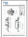


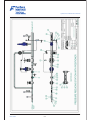


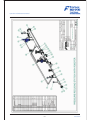


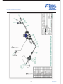
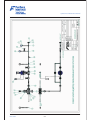


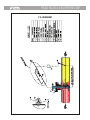
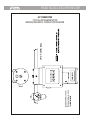


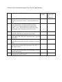

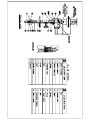


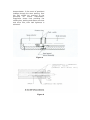


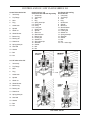


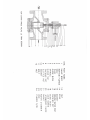


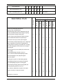


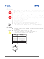


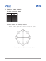


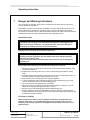

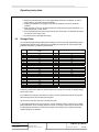

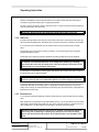


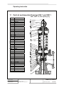


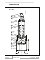


![English [2015v1]](http://vs1.manualzilla.com/store/data/005829431_1-1fdc30543d444fb0915a40c3aab945a8-150x150.png)