1
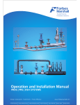
Monec 8965 pH/ ORP TRANSMITTER User’s Manual Monec 8965 pH/ ORP TRANSMITTER User's Manual This user manual corresponds to the Monec 8965 / 8965 Ex pH/ORP transmitter Part Nos. 8965L/8965L-Ex/8965H/8965H-Ex and is the July 2005 revision P.C.No. C2013775. If you experience difficulty with the installation or operation of this equipment, please contact our Customer Service representative. Manufactured and Marketed by Forbes Polymetron Pvt. Ltd. A Forbes Marshall Company A-34/35, MIDC 'H' Block Pimpri, Pune 411 018 INDIA TEL : 91 (0) 20 27442020 FAX : 91 (0) 20 27442040 TLX : (0146) 323 FSON IN 10/04 Dear User, Thank You for purchasing the Monec 8965 pH/ORP transmitter. To maximize your benefits from this product, we request that you read this manual thoroughly before installing the system. A record of the product's maintenance history should be kept in this manual's Field Service Record every time our service representative visits you. What's Inside 1.About The Product 1 General Description Specifications Operating Principle 2.Getting Started 7 Included Items What You Need Mounting Electrical connections Commissioning the Product 3.Operation and Maintenance 20 Front panel details Operating Modes Programming Do's and Don'ts 4.Fixing Problems Troubleshooting Current output calibration Spares Service Field Service Report 36 1 About The Product 1.1 General Description The Monec 8965 pH/ORP transmitter is a Microprocessor operated field mounting instrument to monitor the pH or Redox potential of process solution and transmit 4-20 mA current as a retransmission output. The analyser is designed with modular hardware and user friendly software support. The 8965 range of transmitters are designed to suit intrinsic and non intrinsic applications. In all there are 4 versions of transmitter units in this range. 8965 L : Non intrinsic version with external buffer amplifier. 8965 L-Ex : Intrinsic version with external buffer amplifier. 8965 H : Non intrinsic version with integral buffer amplifier. 8965 H-Ex : Intrinsic version with integral buffer amplifier. The Intrinsic versions are marked as Ex which correspond to the ignition safety classification " Intrinsic safety ' in accordance with IS standard 5780 E Ex ia IIC T5. All these models are compatible to probes equipped with glass, antimony or ORP electrodes. Since the transmitters are Microprocessor operated, all, the application specific parameters are field programmable such as type of electrode, measuring range, type of temperature compensation, calibration mode etc. The unit offers high reliability and easy serviceability due to modular hardware structure reducing maintenance lead time. The software calibration facility allows operation of the instrument without opening the instrument. 1 1.2 Specifications : Sensors Glass, ORP or antimony electrodes Pt 100 temperature sensor Measuring range Parameter Glass Antimony ORP Span Lower end Upper end pH 2/5/10/14 0....12 2....14 pH 5/10/14 0....9 5....14 mV 500/1000/2000 -1500....+1000 -1000....+1500 Temp. Ind. 0... 1300 C Power Supply 15.5.. 30V; the Ex model requires intrinsically safe power supply with 30V/100 mA max. Load 725 Ω max at 30 volts Terminals Screw type, wire dia Ф 2.5 mm2 max Temp. Comp. Automatic : 0 ... 1300 C with Pt. 100 Manual : 0... 1300 C in steps of 10 C Measuring Cycle (t90) < 2 seconds Reproducibility ± 0.1 % FSD I/P Imped. > 1012Ω O/P Signal 4.. 20 mA load 725 Ω, at 30V D.C. galvanically isolated 425 Ω at 24V D.C. Mes. error Output signal: ± 0.1 mA pH measurement: ± 0.2% FSD ORP measurement: ± 3mV FSD Linearity 0.1% Calibration Computer assisted 1 or 2 point calibration Any of two cal. solutions within 0-14 pH for the Zero and slope. Any 1 calibration solution within 0-14 pH for the Zero (asymmetry potential) Zero adj. asymmetry potential ± 2 pH for glass electrodes. ± 5 pH for antimony electrodoes 2 Slope adj. 70-110% of the theoretical slope for glass electrodes. 70-120% of the theoretical slope for antimony electrodes. Storage of measured values Last measurement is retained during calibration and programming Indication 3 1/2 digit LCD 18-mm height. Data I/P Sealed touch keyboard with 4 keys. Electrical connections Model 8965 H : Power supply = 15.5 V<U<32V. Current 20 mA min. Model 8965 H Ex : In order to meet the specifications for intrinsic safety, the auxiliary power must be supplied by a certified, intrinsically safe power supply. Protection "ia" or "ib" U≤30 V icc ≤ 100 mA, linear. Protection "ib" U≤30V icc ≤ 25mA, nonlinear. At 30 V, permissible load is 725 Ω as shown by the following equation : U-15.5 R = -------------0.02 R = load in Ω U = Supply voltage in V. 3 Enclosure Material Epoxy coated cast aluminum Protection IP65 as per DN 40050 Nema4; for wall mounting Dimensions 165Hx165Wx93D mm 200Hx165Wx93D mm with installed cable gland Cable glands 2 Nos 1/2 " NPT, material SS Storage temp. - 20.... + 70 oC Ambient temp. - 10... + 50 oC Weight 1.9 kg Packaging 5 ply corrugated box 4 1.3 Operating Principle The two wire transmitters are charecterised by only two leads serving both as a source of power supply and a means for analog signal transmission. The analog signal is in the form of a 4.. 20 mA DC current. The entire hardware is structured as functional modules assembled together. The DC power supply is converted in split supplies required to drive the processing circuit through a Power pack assembly which is potted for environmental protection and a long sustained life. The potential of the electrodes which represents the process parameter is processed by a high impedance amplifier. The amplifier is situated either inside the transmitter thereby offering high input impedance or can be a "separated external module" which gives output at low impedance. The selection of version is dependent upon the distance required between the electrode and the transmitter. If the distance between transmitter & electrode is less than the length of electrode cable the integral buffer version is suitable. The length of the electrode cable varies depending on the type of electrode or the cable that has been specified in the order. It is typically 3 mtrs, 5 mtrs & 10 mtrs. If the distance of the transmitter from the electrode is greater than the cable length then the external buffer version is required. A special Analog to Digital converter digitises the analog voltage suppressing noise signals, thereby providing for more accurate pH and temperature measurements. The digital data is further processed by a dedicated microprocessor to perform auxiliary functions as display, retransmission output generation, calibration, enabling programming and co-relating programmed data to actual processing. The results are displayed on a 3 1/2 digit LCD display. The application specific parameters such as measuring range, calibration mode and type of temperature compensation are field programmable. The block diagram shown in FIG. I gives a clear picture of data routing and different functional blocks interconnected. 5 Galvanic Isolation I+ LCD Display + 4.5V 0V EEprom Eprom Power Supply - 4.5V OPTO Microprocessor (CPU) Keyboard Impedance Transformer Optical Transmitter Coupler Optical Receiver Output Signal 4...20 mA A/D Converter Impedance Transformer I- Temperature Input pH / mV Signal Input Fig 1 : Block Diagram 6 2 Getting Started 2.1 Included Items When you unpack the carton, use the following checklist to make sure that all of these critical components are present: 1. Transmitter 1 no. 2. Instruction Manual 1 copy 3. 2" NB Pipe mounting kit consisting of I. Pipe mounting bracket (integral with transmitter) 1 no. II. M6 x 20 L bolts 4 nos. Used to fit bracket III. M6 spring washers 4 nos. With transmitter IV. M6 hex nuts 4 nos. V. 'U' clamps 2 nos. Integral with VI. M8 hex nuts 4 nos. each other VII. BSW washers 4 nos. } } 2.2 What You Need 1) 2) 3) 4) 5) 6) 7) 3 1/2 digit multimeter pH/ RTD calibrator Screw driver blade width 6 mm. Instrument screw driver blade width 3 mm. Spanner for M6 nuts. Spanner for M8 nuts. Spanner for 25A/F for cable glands. 2.3 Mounting The transmitter can be mounted either on wall or on a 2" NB pipe. 2.3.1 Wall mounting The casting has 4 holes in four corners as shown in FIG 2.1. The transmitter can be installed in sequence as follows. Since unit has factory fitted wall mounting bracket, it needs to removed for mounting on external wall I. Drill 7 MM through holes in the suitable plate on which the transmitter is to be mounted. II. Hold the unit flat on the mounting plate and insert M6 x 20 L bolts through the four corner holes. III. Fix 4 nos. of M6 spring washers and nuts from the rear end of the mounting plate. IV. Hold the nuts and tighten the bolts with the help of suitable spanner. This completes mounting the transmitter in place. 7 165 mm 150 mm polymetron 165 mm 150 mm Z Select Enter MONEC 35.50 mm 35.50 mm 8965 1/2" NPT SS CABLE GLAND FIG 2.1 : Wall mounting of Transmitter 2.3.2 Pipe mounting The 2" NB pipe mounting kit is supplied along with the Transmitter unit which could be used to mount the transmitter on a 2" NB pipe.The dimensional details of pipe mounting arrangements are as shown in FIG 2.2. The sequence of mounting is as follows : I. Hold the transmitter and the mounting bracket firmly on a pipe and insert 2 nos. of 'U' clamps through the mounting bracket. II. Fix the mounting bracket firmly on the pipe using 5/16" washers and M8 nuts. III. Ensure that the transmitter and the mounting bracket are held properly on the pipe. This completes pipe mounting of the transmitter. 8 6 2 7 3 51 1 3 2 6 4 FIG 2.2 (A) : Horizontal pipe mounting of transmitter (SIDE VIEW) 6 2 7 3 51 3 1 2 6 4 FIG 2.2 (B) : Vertical pipe mounting of transmitter (TOP VIEW) 1 : MONEC transmitter 2 : M6 x 20 Bolts to fix transmitter to mounting bracket. 3 : M8 hex nuts and 5/16" washers to fix 'U' clamps to mounting bracket. 4 : Mounting bracket 5 : Standard 2" NB pipe 6 : M6 hex nuts and M6 spring washers to fix transmitter to mounting bracket. 7 : 'U' clamps to hold transmitter on mounting bracket to standard 2" NB pipe 9 2.3.3 Mounting of external buffer amplifier With models 8965 L and 8965 L-Ex, a separate buffer amplifier module is required. The external buffer amplifier is housed in a wall mounting type casting with two holes of 4 mm dia. at diagonally opposite corners which can be seen after opening the lid on the module. The buffer case should be mounted on a plain surface with the help of 2 nos. of M4 x 15 CH/HD screws, spring washers and hex nuts. FIG 4 shows the locations of these mounting holes. Mounting Holes Mounting Holes FIG 4 : Mounting of external buffer amplifier 10 2.4 Electrical connections All the cables should be routed through the cable glands and rubber seals of the glands before the wires are terminated on the connectors. Care should be taken to avoid mechanical damage while stripping the cables. The cable for pH sensors consists of a screw cap socket at one end. Thread this onto the threads on pH electrode. The other end contains the wires to be connected at the transmitter end. The fig 5 shows this end to identify the proper wires. Sheath Conducting Layer (BLACK) Shield (Ref. Electrode) Insulation Conductor (Glass Electrode) FIG 5 : Electrode Cable - Transmitter Connection End As seen in figure, the cable has a conductive layer between shield and the insulation. This layer needs to be peeled off such that there is sufficient distance between the glass wire and the layer. In case of pH sensor 'Polymetron' make, type '8350' the temperature sensor is inbuilt. This electrode has an integral cable containing the lead wires of pH sensor and Pt100 temperature sensor. The sensor with its integral cable is shown in Fig6. 11 Glass ( Core of inner cable) Ref. (Shield of inner cable) Pt100 (2 wires) FIG 6 : ‘Polymetron’ make, 8350 electrode 2.4.1 Electrical connections for 8965H & 8965 H-Ex Once the instrument is suitably mounted, open the transmitter by unscrewing 2 Nos of knurled captive screws on the transmitter. Shown below in fig. 7 is a part view of the PCB which you will observe an opening. 1 High Mes Ref Pt 100 2 3 Bo3 ImA Ref 4 5 6 Bo2 FIG 7 : Electrical connections for 8965H, 8965H-Ex. (Integral buffer amplifier versions) 12 7 8 Bo1 2.4.1.1 Sensor Connections Connect the 'measuring electrode' (also called as glass electrode) wire of the pH sensor to the Bo3 terminal. The B03 terminal is made of Teflon base with screw terminal at top, where the wire is to be connected. While connecting, guide the pH sensor cable through the cable holder and clamp it by the cable holder nut. Ensure that the 'measuring electrode' wire is not shorted to this clamp. Connect the remaining wire as given below : Terminal No. Wire Description 2 Reference electrode wire of pH sensor 3 Pt 100 (one end) 4 Pt 100 (Other end) 13 2.4.1.2 Power supply connections From the terminals 6,7 & 8 wires have been routed internal to the transmitter to a 3 way terminal block as shown in fig. 8. I mA. + 6 7 8 + Terminal Block On Case Casting FIG 8 : Power Supply Connections for 8965H/H-Ex Connect the transmitter power supply wires at the terminal block. Being a 2 wire transmitter the current o/p is available through these same terminals. 14 2.4.2. Electrical connections for 8965L / L-Ex In these models an external buffer amplifier is provided. Open the lid of buffer amplifier. Shown in fig 9 is the view observed on opening cover. -V Out Ref +V Terminal for glass electrode ( Measuring electrode ) IN Ref Pt 100 Pt 100 Pt 100 Pt 100 Towards 8965L / L-Ex From pH & Temp. Sensor FIG 9 : External Buffer Amplifier connections Also open the transmitter by unscrewing 2 Nos of knurled screws on transmitter. Shown in fig 10 is part view of PCB which is seen on opening. 15 MES -V +V Ref 1 2 3 4 Ref 5 6 7 I mA 8 9 10 FIG 10 : Electrical Connections for 8965L, 8965L-Ex (External buffer amplifier version) 2.4.2.1 Sensor connection Refer Fig. 9 Connect 'measuring electrode' wire of pH sensor to IN terminal. The IN terminal is made of Teflon base with a screw terminal at top where the wire is to be connected. Connected the 'reference electrode' wire of pH sensor & the Pt100 sensor leads at the respective terminals as indicated. 16 2.4.2.2 Inter connection between external buffer & transmitter. This is done by means of 6 core cable and the connections should be made as per wiring shown in Fig. 11. 8965 L/L-Ex External buffer amplifier 7 Pt 100 6 Pt 100 5 Ref 4 Ref +V 3 +V -V 2 -V out 1 Mes Lo Pt 100 FIG 11 : Interconnection diag. between External buffer & 8965L/L-Ex 17 2.4.2.3 Power supply connection From terminals 8,9,10 of 8965 L/L-Ex wires are routed, internal to transmitter, to a 3 way terminal block as in fig. 12. 8965L/L-EX Terminals I mA. + 8 9 10 + Terminal Block On Case Casting FIG 12 : Power Supply Connection for 8965L/L-Ex Connect transmitter power supply wires at the terminal block. Being a 2 wire transmitter the current o/p is available through these same wires. 18 2.5 Commissioning the Product Ensure that the transmitter is mounted firmly on a panel or a pipe as required. Check all the connections of sensor and signal terminals. Tighten the nuts of the cable glands so that the cables are firmly gripped by the rubber seal. This is necessary to prevent ingress of dust & moisture. Connect the buffer terminations properly to the transmitter in case of external buffer versions. Ensure that the external buffer is mounted firmly. Calibrate the electrode to be used in process. For this operation read the section 3 of this manual thoroughly. Follow instructions given in the procedure calibration of electrodes of the same section. Mount the sensor carefully in the process pipe or tank as per the application. Connect power to the transmitter and check the performance. 19 3 Operation and Maintenance polymetron Select polymetron Enter Ex Select Monec 8965 Enter Monec 8965 Intrinsically safe version Non Intrinsic version FIG 13 : Front Panel Fig 13 shows the front facia for the transmitters. The "Ex" symbol indicates that the instrument has intrinsically safe electronics. The display is 3 1/2 digit LCD module. The four nos. of keys can be grouped as 1) The Rollkeys Increase the value Decrease the value In programming mode, upon first pressing the rollkeys, the selected values change slowly in steps. After approximately 10 steps, the rate of change accelerates and the desired setting is quickly reached. 20 2) The Select key Pressing “Select” while in the measurement mode transfers the program into the display mode. Once in this mode, various parameters can be retrieved and read but no changes are possible. Simultaneous pressing of “Select” and “Enter” keys activates the programming mode. In this mode, desired parameters can be chosen with “Select key”. The whole program can be scrolled by pressing “Select key” continuously. 3) The Enter key This key returns the program into measurement mode after storing the programmed settings. If “Enter” is pressed during calibration, the latest measurement data is displayed. 3.2 Operating modes The instrument offers 3 different operating modes. Programming mode : This mode can be enabled by pressing “ Select " and " Enter " keys simultaneously. The prompt " Pr " indicates that programming mode is invoked. Display mode : By pressing " Select " key alone enables entry in display mode. In this mode, all the operating parameters can be " read only " and no alterations are possible in any operating parameter. Measurement mode : In this mode, the instrument carries out routine measurements according to operating parameters programmed. In order to enter programming mode at any point of time, " Select " and " Enter " keys need to be pressed simultaneously. Note : Whenever programming is aborted to enter measurement mode, a prompt " MES " appears on the display for some time before displaying measured parameter. 21 3.3 Programming The programming is done with that 4 keys on the front facia. Various fonts displayed during the programming are shown in the following table to help understand the mode and parameter to be programmed. LEC Operating mode "display” Pr Operating mode "programming" Std Standard glass electrode Sb Antimony electrode rEd ORP electrode (Redox electrode) CAL Calibrate the pH electrodes E1 Calibration solution 1 E2 Calibration solution 2 PAr Display the calibration parameters (asymmetry in pH units, slope in%) ECH Measuring ranges assigned to the outputs InF Lower end of range (output 4 mA) SuP Upper end of range (output 20 mA) t0C Temperature measurement & compensation Aut Automatic temperature compensation and measurement with Pt 100 MAn Manual temperature compensation with fixed reference. MES Operating mode "Measurement” Note : Please note that pressing of “Select” key alone will enable "Display" mode wherein alternation of any parameter is not allowed. In order to invoke "Programming" mode, both “Select” and “Enter keys” need to be pressed simultaneously. The sequence of programming is illustrated in the flowchart in FIG 7. 22 Press “SELECT” and “ENTER” keys simultanously START Displays “Pr” Select type of electrode Std Std Sb Sb rEd rEd No Yes Enter ? Displays “MES” Return to measurement mode Select ? A Continued 23 A Values shown in this flowchart are indicative only Displays “CAL” Set value of calibration solution 1 Flashing Arrow Indicates that calibration adjustment is possible 4.00 No No Enter ? Select ? Yes Without calibration Yes Displays “E1” Set value of calibration solution 2 9.00 D C 24 Continued B C D No Enter ? B Yes Select Yes No One Point Caliberation Displays “E2” No No Enter ? Yes Select ? Yes Two Point Caliberation Displays “MES” Displays “PAr” Return To Measurement Mode No No Enter ? Yes Select ? Yes Displays the asymmetry & slope parameters alternately 1.00 Asymmetry 100 Slope Displays “MES” E Return To Measurement Mode 25 Continued E Displays “ECH” Displays “Inf” first and then “SuP” Select measurement range Select lower & upper ends of measurement range 10.00 2.00 12.00 No No Enter ? Select ? Yes Yes Yes Enter ? No Displays “MES” Return to measurement mode Yes F Continued 26 Select ? No F Displays “t°C” Yes Select ? Select mode of temp. measurement and compensation No Aut Man Return to electrode selection at START Yes Enter ? No Displays “MES” Select ? Return tc measurement mode F Continued 27 G Automatic Manual Press “Select” and “Enter” keys simultaneously to update temperature in “Auto” mode Set the temperature Set the temperature 10° No 18° Enter ? No Yes Yes Enter ? Displays “MES” Return to measurement mode No Select ? Yes Yes Return to electrode selection at START 28 Select ? No 3.3.1 Programming step The programming mode is accessed by simultaneously pressing Select and Enter. The symbol: Pr appears 3.3.1.1 Selecting type of electrode Using the rolikeys, choose any one of 3 electrode types ! Glass electrode ! Antimony electrode ! ORP electrode Pressing Select confirms the choice and moves the program to the next step. 3.3.1.2 Calibrating for the electrodes Calibration entails the comparison and adjustment of the measured pH with that of a known buffer solution or a process solution of an accurately known pH. Either one or two calibration solutions may be used. At the start of the calibration mode, the symbol CAL appears, followed by the display of the measured pH. At the same time, a flashing arrow indicates that the instrument is in the programming mode. 1 0.05 29 Now immerse electrodes into a buffer solution. Wait for the pH reading to stabilize. Using the rollkeys, adjust the display until the indicated pH corresponds to the pH of the buffer solution. Do not press select at this stage, as the instrument will advance to next step of program, without any calibration. Press enter The symbol El appears temporarily, followed by display of corrected pH value. There are now two options: 1. Single-point calibration (any one buffer) Confirm with Select to fix the adjusted pH value. During the course of this calibration, the instrument determines that : a)The deviation of the zero is within the factory-set limit of ±2 pH units for glass electrodes or ±5 pH units for antimony electrodes. In this case, the actual zero is calculated and the calibration is accepted. The instrument automatically advances to the next step of the program. (if, at this point, you prefer to return directly to routine measurements (measurement mode), simply press Enter.) b)The deviation of the zero is in excess of the factory-set limits. In this case, a correction is not possible; the symbol Er1 appears in the display. For routine measurements, the instrument will use the theoretical zero=O mV. Since the risk of substantial errors is very real, it is better to repeat the calibration with new electrodes and/or fresh buffer solution. 30 2. 2-point calibrations with any of two buffers (Choose buffers whose nominal pH values are substantially different. The pH value of the second buffer solution can be either greater or less than the pH value of the first .) Immerse the electrodes into the second buffer solution. Using the rollkeys, adjust the pH until it corresponds to the pH of the Confirm by pressing Enter. Now the symbol E2 appears temporarily, followed by the corrected pH. Press Select to display the asymmetry potential and the slope. During the course of this calibration, the instrument determines that : a)The deviation of the slope is within the factory-set limit of 70-110% for glass electrodes or 70-120% for antimony electrodes. In this case, the actual slope is calculated and the calibration is complete. Press Enter to return to routine measurements (measurement mode). b)The deviation of the slope is in excess of the factory-set limits. In this case, a correction of the slope is not possible; the symbol Er2 appears in the display. Since the risk of substantial errors is very real, it is better to repeat the calibration with new electrodes and/or fresh buffer solution. ORP electrodes are not calibrated. The transmitter functions as a milli voltmeter indicating absolute mV values. Buffer Solutions : The pH of buffer solutions is dependent upon the temperature, e.g., the nominal pH values are referred to a temperature of 20 Deg.C. For temperatures other than 20 Deg.C, the calibration with the buffer solution must be done at the sample temperature. 31 3.3.1.3 Displaying the parameters This program step displays the deviations of the asymmetry potential and the slope from their respective nominals. The symbol PAr appears and the actual deviations for the zero and the slope are displayed alternately. The signs "+" or "-" indicate either a positive or a negative deviation of the asymmetry potential. The % slope deviation is expressed with respect to the theoretical slope of 59.2 mV/pH at 25 Deg. C. In the display mode, these parameters appear immediately after the display of the electrode type. 3.3.1.4 : Selecting span of measurement Depending upon the type of electrode, the following ranges are available : a) Glass electrode : 2-5-10-14pH b) Antimony electrode : 5-10-14 pH c) ORP electrode : 500-1000-20OOmV Select and confirm with Select. Whatever the selection, the measuring range always refers to the range appearing at the analog output. 32 3.31.5 Selecting working range The symbols InF and SuP indicate alternately the lower and upper ends of the range. Measuring Ranges pH 2 pH 5 pH 10 pH 14 500 mV 1000 mV 2000 mV 0-2 0-5 0-10 0-14 -1500 -1000 -1500 -500 -1500 +500 1-3 2-7 2-12 -1250 -750 -1000 0 -1000 +1000 2-4 3-8 4-14 -1000 -500 -500 +500 -500 +1500 3-5 4-9 -750 -250 0 +1000 4-6 5-10 -500 0 +500 +1500 5-7 6-11 -250 +250 6-8 7-12 0 +500 7-9 9-14 +250 +750 8-10 +500 +500 +1000 9-11 +750 +1250 10-12 +1000 +1500 12-13 12-14 33 3.3.1.6 Temperature compensation In the display appears the symbol Aut or MAn for automatic temperature compensation with Pt100 or manual temperature compensation with a fixed reference temperature. Temperature Adjustment with Automatic Temperature Compensation : By simultaneously pressing Select and Enter the symbol t IC appears, followed by the display of the measured temperature. This value can now be adjusted to a nominal value with the roilkeys. Temperature Adjustment with Manual Temperature Compensation : Confirm the adjustment with Select or Enter. 34 3.4 DO'S and DON'TS ! Don't ever try to adjust the potentiometers on CPU board. ! Don't leave the pH electrode dry. ! Don't expose the screw cap connector on the sensor to moisture. ! Don't press the keys too hard while programming. ! Do ensure that the transmitter and buffer are mounted firmly on panel or pipe as application demands. ! Do use the same electrolyte as mentioned on the electrode while refilling. ! Do use the proper tools while removing / making electrical connections. 35 4 Fixing Problems 4.1 Troubleshooting The MONEC transmitters being microprocessor based, offer self diagnostic and error reporting feature. This feature enables the user to identify the possible cause of the problem and decide the remedy for the same. The error messages and their meaning are as listed below. ERROR MESSAGE FAULT NATURE ACTION Er 0 Incorrect programming Check the parameters programmed and correct wrong entry. Er1 Asymmetry potential exceeding factory set limits 1) Recalibrate electrode : 2) If error still occurs after this clean the electrode & again recalibrate. 3) If error still appears replace electrode & calibrate again Er 2 Slope potential exceeding factory set tolerance 1) Recalibrate electrode : 2) If error still occurs after this clean the electrode & again recalibrate. 3) If error still appears replace electrode & calibrate again Er3 Pt 100 leads shorted Check the resistance between Pt 100 leads and rectify or replace the sensor Er4 Pt 100 leads are broken or disconnected Check the resistance between Pt 100 leads and rectify or replace the sensor 36 4.2 Current Output Calibration The current output is factory calibrated and does not require to be adjusted again. Hence carry out this operation only if you find that the current output is outside the specified accuracy limits. ! Switch OFF the instrument. ! Press roll keys (increment & decrement keys) simultaneously and switch ON the instrument. ! Release the keys when message 'lout' appears on display. ! This message is followed by display '4' (represents setting of 1=4 mA) and is immediately followed by a display of coefficient. ! Measure current output on current meter (The meter is to be connected in series with power supply & transmitter) Press increment or decrement key to increase or decrease the current output so as to get 4 mA reading on the meter. ! Press 'select' key. ! Message '20' is displayed and is followed by display of another coefficient. ! Press increment or decrement key to get 20 mA reading on meter. ! Press 'select' key. NOTE: i)Reprogram the instrument in the desired configuration as all previous settings are altered by the above operation. ii)Recalibrate for the sensor as the previous sensor calibration is also disturbed. 37 4.3 Spares Part code No. Description C2013711 CPU board assembly C2013737 Power supply board assembly 8965 L C2013713 Power supply board assembly 8965 L-Ex C2013725 Power supply board assembly 8965 H-Ex C2013723 Power supply board assembly 8965 H C2013785 External Buffer PCB assembly (applicable in 8965 L/L Ex models only) C2018807 Cable gland assembly C2013775 Instruction manual 38 4.4 Service If you still need help, please contact your nearest Forbes Marshall representative. The addresses and contact numbers of our major branches are listed on the back of this manual. They'll be happy to direct you to any representative in your area, or provide service themselves. Please record all instances of field service problems and actions taken in the space below: Product Serial Number : Date Problem Action Taken 39 Serviced by 4.5 Field Service Report This form should be used to report field problems. A copy should be filled out by your Forbes Marshall customer service engineer. Any servicing which requires the product to be sent back to Works cannot be completed without this report. If the product is returned to our Works, you should include either the original excise gate pass or our invoice number and date. If you'd prefer an estimate before proceeding with repair: You should clarify on the form whether you would like to have the cost estimate before we make any necessary repairs. If you indicate that an estimate is required, our Works Engineer will complete Part 6 of the form and return it to you. If this estimate is satisfactory, you should approve the estimate and return the approved form to your Forbes Marshall representative. Only then will servicing proceed. 40 Forbes Marshall Field Service Report Report # : Date : Division 1) Customer Information Customer Name : Address : Site Contact Person : Phone : Reference: 2) Product Information Product Description : Serial Number : Original Invoice # Date : Input/Inlet Details : Output/Outlet Details : The Product is On-line Off-line Connections Flanged Screwed Mounting Details : 3) Application Information Process Media : Pressure : Temperature : Sensor Details (If any) : Mounting Details : 41 Welded 4) Observed Problems or Symptoms 5) Proposed Action Repair at Site Return to Works Estimate First 0r Under Warranty Field Engineer's Sign :Customer's Signature : 6) To be Filled in for Estimate Purpose Estimated Cost : List any imported spares which must be provided by Customer : Signature of MFG/CSD Engineer. 7) Customer's Endorsement We accept the above repair estimate Signature & Stamp. 42 5 Notes Notes Notes MANUFACTURING UNITS PUNE - KASARWADI PB 29 Mumbai-Pune Road, Kasarwadi Pune - 411 034. Tel : 020-27145754 DID : 020-27149012 Fax : 020-27147379 http://www.forbesmarshall.com/spirax Solutions Engineering If You Need Help... PUNE - MIDC A-34/35, MIDC, ‘H’ Block, Pimpri Pune - 411 018. Tel : 020-27442020 Fax : 020-27442040 [email protected]/spirax http://www.forbesmarshall.com/spirax HYDERABAD Plot No. A-19/2 & T-4/2 I.D.A. Nacharam, Hyderabad - 500 076 Tel : 040-27152276 / 27170732 / 27171909 / 27153918 Tel : 040-27151664 Fax : 040-27173235 / 27179223 / 27152193 [email protected] / [email protected] BRANCHES ACROSS INDIA AHMEDABAD 4 Shetoor Bunglows Opp. Drive In Petrol Pump Near Chandandwar Hospital T V Tower, Ahmedabad - 380 054 Tel : 079-26851738 / 26856374 Direct: 079-26859395 Fax : 079-26854014 [email protected] DELHI - (Control Instrumentation Group) Anupama Arcade, 2nd Floor Opp. Samachar Apts. Mayur Vihar, Extn. Phase 1 New Delhi 110 091 Tel : 011-22713485 / 22712902/3 Fax : 011-22710484 [email protected] / [email protected] ALIBAG Pent House No. 1 Bafna Baug Complex-B Behind Big Splash Hotel Chendhare Alibag 404 201 Tel : 02141-223795(O) Fax : 02141-223796(O) [email protected] HYDERABAD Plot No. A-19/2 & T-4/2 I.D.A. Nacharam, Hyderabad - 500 076 Tel : 040-27152276 / 27170732 / 27171909 / 27153918 Tel : 040-27151664 Fax : 040-27173235 / 27179223 / 27152193 [email protected] / [email protected] BANGALORE 21 Coles Road, Cleveland Town Bangalore - 560 005 Tel : 080-25483047/25485626/25484281 Fax : 080-25499971 [email protected] CHANDIGARH SCO # 77, Top Floor Sector 38-C, Chandigarh Tel : 0172-5080285 Fax : 0172-695098 [email protected] CHENNAI Plot #. 59, Montieth Rd. Asha Mansion, Egmore Chennai - 600 008 Tel : 044-28554493 / 28553011 Fax : 044-2855380 [email protected] COIMBATORE Flat No. 4C, Classic Garden Apts 1552/19 Trichy Rd. Coimbatore - 641 018 Tel : 0422-2303679/22306015 Fax : 0422-2300072 [email protected] DELHI - (Steam Engineering Group) 24, Laxmi Insurance Bldg. Asaf Ali Rd., New Delhi - 110 002 Tel : 011-23232947/23232756 Fax : 011-23233762 [email protected] JAMSHEDPUR 59, Rajendra Nagar Jamshedpur - 831 001, Jharkhand Tel : 0657-2437721 Telefax : 0657-2427983 [email protected] KOLKATTA 5A Orient Row, Kolkatta - 700 017 Tel : 033-22407359 / 22835807 /22835809 Fax : 033-22475280 [email protected] PUNE PB 29 Mumbai-Pune Road, Kasarwadi Pune - 411 034. Tel : 020-27145754 Fax : 020-27147379 [email protected] SURAT 7B Ground Floor, Navchetan Society Opp. Krushimangal Hall, Ring Rd. Surat - 395 007 Telefax : 0261-2651448, 2650896 [email protected] VADODARA 10, Shreeji Krupa Society Gotri Rd. B/H Kalpavruksha Complex Subhanpura P.O. Vadodara - 390 023 Tel : 0265-2343733 Direct : 0265-2342234 Fax : 0265-2337930 [email protected] VISAKHAPATNAM 403, Crescent Towers Opp. Enadu, Seethammadhara Visakhapatnam - 530 013 Tel : 0891-2552538 Fax : 0891-2535576 [email protected] MUMBAI 107, Mahatma Gandhi Road Mumbai - 400 023 Tel No : 022-2267 3821, 2267 3822 Fax : 022-22672970 [email protected] REPRESENTATIVES NAGPUR 50,ASHA 2nd Floor Lendra Park, New Ramdaspeth Nagpur - 440 010 Tel : 0712-2539386 Telefax : 0712-2549851 [email protected] Indore 36/A, Narmala Nagar Annapurna Rd., Indore - 452 009 (M.P.) Tel : 0731-5058030 Cellular : 0731-3102220 / 098260-17398 NAVI MUMBAI “Ellora” Sector 14 /Plot No.45 Opp. Marathe Bhavan Vashi, Navi Mumbai - 400 705 Tel : 022-27666157/27655969 Fax : 022-27881533 [email protected] BHOPAL MIG 24/2A, Saket Nagar, Bhopal Tel : 0755-2582710 Cellular : 098261-62047 MADURAI 55, LIG Colony, K K Nagar Madurai - 625020 PONDICHERRY [email protected]