1
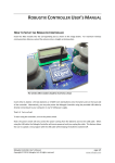
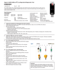
4411e Electromagnetic Flow Transmitter Instruction Manual Copyright 2008. All rights reserved, EMCO Flow Systems, A division of Spirax Sarco, Inc. Released September 2008 / R7 / Software Version 2.02 EMCO Flow Systems Product Limited Warranty Statement EMCO Flow Systems (EMCO) warrants each UniMag magnetic flow metering system to be free from defects in material and workmanship under normal use and service for the following periods from the date of purchase: Note: EMCO may recommend materials that come into contact with the media. However, EMCO cannot guarantee the compatibility of those materials for any specific application, and does not include compatibility in its warranty. UniMag Sensors And Flowtubes 2 year warranty, except when temperatures and pressures exceed approved customer application data. DemiMags 1 year warranty ChannelMag 1 year warranty Transmitters 1 year warranty The user must provide any notice of any defect to EMCO within the warranty period, thoroughly clean the product, return intact and prepay transportation charges. The obligation of EMCO under this warranty is limited to repair or replacement at its factory. This warranty shall not apply to any product which has been repaired or altered by non EMCO employees, or which has been subject to misuse, negligence, accident, or incorrect wiring by non EMCO employees. The 4411e transmitter contains a tamper seal on the field wiring board. If this sticker is removed or damaged the warranty will be void. 2150 Miller Drive • Longmont, CO 80501 Phone: 800-356-9362 or 303-682-7060 • Fax: 303-682-7069 email: [email protected] • website: www.emcoflow.com FOREWORD This instruction manual is designed to help you gain a thorough understanding of the operation of the equipment. EMCO Flow Systems (EMCO) recommends that you read this manual completely before placing the equipment in service. Although EMCO designs reliability into all equipment, there is always the possibility of a malfunction occurring. You can use this manual to help in diagnosing and repairing the malfunction, if possible. If the malfunction persists, call or write the EMCO Customer Service Department for assistance. Address and contact information: EMCO Flow Systems 2150 Miller Drive Longmont, CO 80501 Phone: 800-356-9362 or 303-682-7060 Fax: 303-682-7069 email: [email protected] website: www.emcoflow.com For other countries, consult your nearest EMCO representative. Simple difficulties can often be diagnosed over the phone. If it is necessary to return the equipment to the factory for service, please read our Return Authorization Policy on the following page. This will aid in the prompt repair and return of the equipment. EMCO welcomes suggestions that would improve the information presented in this manual or enhance the operation of the equipment itself. IMPORTANT NOTICE RETURN AUTHORIZATION POLICY EMCO Flow Systems (EMCO) must pre-approve and assign a Return Authorization Number to any instrument you plan to return. Please identify the Return Authorization Number clearly on all shipping cartons and paperwork. Please note that the provision of a Return Authorization Number does not automatically mean that the return is covered by our warranty. In order to serve you better, and to protect our employees from any potentially hazardous containers, EMCO MUST RETURN UNOPENED, AT THE SENDER’S EXPENSE, ALL ITEMS THAT DO NOT HAVE A RETURN AUTHORIZATION NUMBER AND DECONTAMINATION CERTIFICATE. To obtain a Return Authorization Number, EMCO requires a completed Decontamination Certificate, which states that equipment to be returned has been thoroughly cleaned. To receive a copy of this document, please contact EMCO and request a Decontamination Certificate. Phone: 800-356-9362 or 303-682-7060 Fax: 303-682-7069 email: [email protected] website: www.emcoflow.com Please note that we will be unable to issue a Return Authorization Number unless we have a completed Decontamination Certificate. This ensures everyone’s safety and helps us speed up the repair and return process. OSHA Hazard Communication Standard 29CFR 1910.1200 mandates that we take special steps to protect our employees from exposure to potentially hazardous materials. Therefore, all equipment so exposed must be accompanied by a completed Decontamination Certificate prior to issuance of an RA number by EMCO. The employees of EMCO sincerely appreciate your cooperation in following this policy. Address your equipment to: EMCO Flow Systems 2150 Miller Drive Longmont, CO 80501 IMPORTANT – PLEASE READ DANGER The installation and operation of this product may put you at risk of serious injury or even death. The electrical installation, start-up and maintenance of this device must be performed by trained personnel authorized by EMCO. The personnel must read and understand this Instruction Manual and follow its procedures. Take whatever precautions are necessary to ensure your safety before making an installation or working on one. Never work alone or unsupervised. Install and operate this product in accordance with all applicable safety and health regulations, as well as any appropriate local ordinances. Observe the national standards in your country applicable to testing the operation, repair and maintenence of electrical devices. This product may be installed in confined spaces. Examples of confined spaces are manholes, pipelines, digesters, and storage tanks. These places can be dangerous or fatal if you are not suitably prepared. The primary hazards of confined spaces are the possibility of poisoned air and the lack of proper ventilation. Work in such places is governed by OSHA 1910.146, and may require a permit before entering. The other major hazard particular to this product is its extreme weight, which makes it dangerous to handle and creates the risk of being crushed or struck by the unit during installation. This manual may also contain Material Safety Data Sheets (MSDS) for chemical agents supplied or recommended for use with this product. If needed, these sheets will be in the MSDS Appendix. These sheets provide information about possible hazards from the chemicals. Additional MSDS, covering various proprietary agents (name-branded or trademarked mixtures) that can also be used with this product, are available from the manufacturers of those agents. This manual uses the following notations to set apart hazard warnings and notes: DANGER DANGER describes situations that will result in loss of life or serious personal injury, unless avoided. The emphasis is on clear and immediate threats to your life or safety. WARNING WARNING describes situations that could result in loss of life or serious personal injury unless avoided. The emphasis here is on the potential for a serious accident. CAUTION CAUTION describes situations that may result in moderate personal injuries, property damage, or damage to the equipment, unless avoided. Note NOTES draw your attention to particular features, practices, tips, or other information useful in setting up or operating the product. 4411e Electromagnetic Flow Transmitter Table of Contents Section 1 Introduction 1.1 1.2 1.3 1.4 Introduction Summary of Features Specifications for the 4411e Transmitter Identification 1 1 1 4 Section 2 Installation Procedures 2.1 The 4411e Transmitter Dimensions 2.2 Mounting the Transmitter 2.3 Wire Entrances and Conduit Connections 2.4 Access to Terminals and Printed Circuit Boards 2.4.1 Printed Circuit Boards 2.5 Connecting the Flowmeter 2.5.1 Multiple Flowmeters 2.5.2 Cable Connections 2.5.3 Sensor Coil Resistances 2.5.4 Connecting the Power Supply 2.5.5 Inputs and Outputs 5 6 7 8 9 10 10 10 18 18 19 3.1 3.2 3.3 3.4 3.5 3.6 3.7 21 21 22 22 24 24 25 25 26 26 27 28 29 29 31 53 Section 3 Operation Introduction Keypad and Display Panel Powering Up the Unit The Default Display Online and Offline Status Setting Date and Time Setup Identity 3.7.1 Entering Identity Information 3.7.2 Displaying Identity Information 3.8 Setting Up Passwords 3.9 Setting Flow Direction and Rate 3.10 Setting Up the Reference Mode 3.11 Setup Totalizers 3.12 Non-Full Pipe Detection 3.13 Menu Structure Diagrams 3.14 Example Setup Routine for Frequency or Pulsed Output Section 4 Troubleshooting 4.1 Quick Guide to Troubleshooting 4.1.1 Serial Numbers 4.1.2 Resistances 4.1.3 Connecting Field Input/Outputs 4.1.4 Connecting the Power Supply 4.1.5 Programming the 4411e Transmitter 4.1.6 4411e Troubleshooting Guide 55 55 55 56 56 57 59 4411e Electromagnetic Flow Transmitter Table of Contents Section 5 Revalidation of Electrical Parameters Certificates 5.1 Revalidation Program 61 Section 6 Additional Resources 6.1 Additional Resources Available 63 List of Figures 2-1 4411e Front Panel Dimensions 2-2 4411e Bottom Dimensions 2-3 Mounting Feet and Attached Mounting Foot 2-4 Recommended Use of Conduit Holes 2-5 Plug Assembly 2-6 Dip Switch Settings for 4-20 mA Outputs 2-7 ChannelMag / 4411e Connection Diagram 2-8 4411e Connection Diagram 2-9 4411e Connection Diagram, 1 or 2 Sensors 2-10 4411e Connection Diagram, 4 Sensors 2-11 4411e Connection Terminals 2-12 Power Supply Connections on Connection Board 2-13 4411e Inputs and Outputs 3-1 4411e Transmitter – Keypad and Display 3-2 Menu Diagram – Top Level of Menus 3-3 Menu Diagram – Reset Totals 3-4 Menu Diagram – Clear Alarms 3-5 Menu Diagram – Diagnostics 3-6 Menu Diagram – Field Start-Up 3-7 Menu Diagram – System Setup 3-8 Menu Diagram – Passwords 3-9 Menu Diagram – Reference Mode 3-10 Menu Diagram – Default Display 3-11 Menu Diagram – Totalizers 3-12 Menu Diagram – Flow Rate 3-13 Menu Diagram – Analog Outputs 3-14 Menu Diagram – Serial Comms 3-15 Menu Diagram – Pulse Output 3-16 Menu Diagram – Setup Identity 3-17 Menu Diagram – Relay Outputs 3-18 Menu Diagram – Contact Outputs 3-19 Menu Diagram – Calibrate and Test 3-20 Menu Diagram – Setup 50/60 Hz Mode 3-21 Menu Diagram – System Utilities 3-22 Menu Diagram – Setup Diagnostics 3-23 Example Setup Routine for Frequency or Pulsed Output 4-1 4411e Troubleshooting Guide 5 5 6 7 7 9 12 13 14 15 16 18 19 21 32 33 34 35 36 37 38 39 40 41 42 43 44 45 46 47 48 49 50 51 52 53 59 List of Tables 1-1 4411e Electromagnetic Flow Transmitter Specifications 2-1 Terminal Identification 2-2 Cable Connections 2-3 120V Sensor Coil Resistances (Ohms) 1 8 10 18 4411e Electromagnetic Flow Transmitter Section 1 Introduction 1.1 Introduction A UniMag electromagnetic flow meter system consists of a flow sensor and a 4411e microprocessor based transmitter. 4411e transmitters use a unique and innovative method of coil excitation to create a stable flow signal having a signal-to-noise ratio higher than conventional AC or pulsed DC magmeters. As a result, the system offers fast response, high accuracy (unaffected by zero drift), and unequaled insensitivity to the worst slurry generated noise. The 4411e can be operated, configured, and calibrated locally from the front panel’s keypad and display window. 1.2 Summary of Features The following list summarizes the major functional capabilities and options available with the 4411e: • Bidirectional flow measurement capability. • Two analog (4-20 mA) outputs that can be individually configured. • Pulse output that is configurable as a scaled totalizer value or as a frequency that is proportional to the flow rate. • Totalizer that maintains Forward, Reverse, Net, and Gross Total values in user specified volume units. • Two Contact Inputs that can be programmed to acknowledge alarms, reset totals,or force zero flow. • Two Relay Outputs that can be configured as high alarm, low alarm, diagnostic error, flow direction, or empty pipe. The alarm set points may be based on flow rates or totalizer values with a programmable dead band. You can also choose if alarms clear themselves or must be manually acknowledged when the alarm condition returns to normal. • Two levels of password protection that allow you to prevent undesired modification of the configuration parameters and/or resetting of totals and alarms. • A 4-line x 20-character backlighted LCD display with keypad. 1.3 Specifications for the 4411e The technical specifications for the 4411e are listed in Table 1-1. Table 1-1 Height Width Depth Weight Material Keypad Display 4411e Electromagnetic Flow Transmitter Specifications 9.4 inches (24 cm) 9.8 inches (25 cm) 4.4 inches (11 cm) 7 pounds (3.2 kg) UV resistant fiber glass with stainless steel screws Tactile feedback, waterproof, vandal resistant Waterproof, backlit liquid crystal, 4 lines of 20 characters each 4411e Electromagnetic Flow Transmitter Section 1 Introduction Totalizers Operating Temperature Storage Temperature Enclosure Supply Voltage Mains Power Fuse Coil Protection Fuse Power Consumption at 120 VAC 60Hz Compatible Flowtubes Sensor Excitation Magnetizing Current Forward, reverse, net and grand total flow, resettable or non-resettable -4 to +140°F (-20 to +60°C) -40 to +160°F (-40 to +70°C) NEMA 4X, IP65 120 V 60Hz, 120 V 50Hz, 230 V 50 Hz 250 mA @ 120 Vac supply, slo-blo 125 mA @ 230 Vac supply, slo-blo Dimensions: 5 x 20mm 5A fuse 4411e Transmitter 6 Watts typical Max for Sensors 65 Watts typical See Section 2.5 UniPulse (unipolar pulsed AC) Up to 5.5 A base to peak, depending on sensor size Coil Voltage 120 Vac, 60 Hz, 230 Vac, 50 Hz or 120 Vac, 50 Hz Exciter Frequency 40 Hz (with 60 Hz) or 33.3 Hz (with 50 Hz) 1012 Ohms 5 µS/cm standard, 0.08 - 5 µS/cm with booster pre-amp. For deionized water, consult EMCO. Using sensor electrodes or user supplied signal, holds analog output at 4 mA and pulse output at 0. A low flow cutoff algorithm forces the pulse output, display, and digital measurement value to zero when the measurement signal falls below user adjust able setpoint. The default is 2% of 4-20 mA flow range. Minimum of 30 milliseconds Less than ±0.5% of span for any temperature variation. Two user configurable inputs, rated 12 volts DC, 10 mA. These inputs require a contact closure or transistor switch between the terminals. RS232 proprietary protocol for software updates and configuration. Input Impedance Media Conductivity Non-full Pipe Detection Low Flow Cutoff Time Constant Temperature Coefficient Contact Inputs (2) Communications 4411e Electromagnetic Flow Transmitter Section 1 Introduction Analog (4 to 20 mA) Outputs Two 4-20mA outputs from separate terminals are available for bidirectional flow. When internally powered, a loop voltage of 24 V DC is supplied with a maxi mum load of 800 Ohms. Theses outputs are not potential free, but are isolated from ground and all other circuits, but not from each other. Signal Damping Pulse Output Scaled Mode (for totalizing) Frequency Mode (for rate indication) Relay Outputs (2) Maximum Distance Between Flow Transmitter and Flowtube When externally powered, the maximum load is calculated by: Max. Ohms = [(Vdc x 50) - 300] For an external 24 Vdc supply, this would be [(24 x 50) - 300] = 900 Ohms. Minimum current 3.75mA, maximum 22mA 0 to 300 seconds Two-wire, externally powered, configurable as a scaled output (for totalizing flow) or frequency output (for rate of flow). Rated 5 - 42 volts DC, 200 mA. Medium: 50 ms pulse width with maximum frequency of 10 Hz Fast: 5 ms pulse width with maximum frequency of 100 Hz Square wave output, 0 - 1,000 Hz, 0 - 2,000 Hz, 0 - 5,000 Hz, 0 - 10,000 Hz Two user configurable form C (changeover) relays, activated based on forward or reverse flow, forward or reverse total, net total, gross total, or analog in sig nal. Contact rating 125V AC, 1A, 30VA. 300 feet or 66C (100m or 20C), whichever is less, for conductivity > 5 mS/cm where C is conductivity in in mS/cm (micromhos/cm). For cable lengths > 100 feet (30m) or conductivities < 5 mS/cm, a preamp in the magmeter is necessary. 4411e Electromagnetic Flow Transmitter Section 1 Introduction Wiring From Flow Transmitter to Flowtube Supply Voltage Requirements and External Loop Load Limitations Pulse Output 1.4 Transmitter Identification Three cables are required; one for the reference coil (which compensates for variation in supply voltage), one for the electrodes, and one for the exciter coils. Each cable should be 50 feet (15 m) standard, twisted shielded pair, 18 gauge (0.75 mm2) minimum, Belden 8760 or 9318, Alpha 5610/1801 or 5611/180, or equivalent. A pre-amp cable is optional. 4 to 20 mA Output, Externally Powered: The supply voltage will vary depending upon the load resistance. Refer to Table 2-1 for details. Externally powered, 5 to 42 volts DC The transmitter can be identified by a data plate located behind the door of the enclosure. Although all 4411e transmitters are interchangeable with all UniMag flowmeters, they are normally supplied already calibrated to a particular magnetic flowmeter. 4411e Electromagnetic Flow Transmitter Section 2 Installation Procedures 2.1 The 4411e Transmitter Dimensions The dimensions of the 4411e transmitter are shown in Figures 2-1 and 2-2. Figure 2-1: 4411e Front Panel Dimensions Figure 2-2: 4411e Bottom Dimensions 4411e Electromagnetic Flow Transmitter Section 2 Installation Procedures 2.2 Mounting the Transmitter The 4411e transmitter must be mounted where it will never be submerged in water. When properly installed, the 4411e is dust tight, corrosion resistant, and protected against water jets, to NEMA 4X and IP65. Although the 4411e has high insensitivity to electrical noise, it is preferable to locate it and the flowtube away from high voltage, radio frequency, and similar external noise. It should not be located in direct sunlight, and proper ventilation is required to circulate the air in the immediate area around the transmitter. Location in areas of high moisture content should be avoided to prevent excessive buildup of moisture inside the enclosure. If this is unavoidable, an appropriate heater should be used in the transmitter location. The ambient air temperature should be within -4°F to +140°F (-20°C to +60°C) for operation. This temperature range can be -40°F to +160°F (-40°C to +70°C) for storage. The transmitter is intended to be a wall mounted unit, and is normally supplied with mounting feet. The feet (Figure 2-3) can be used for mounting the enclosure, or holes can be made in the mounting panel to match the four tapped holes in the back of the 4411e enclosure (Figure 2-1). Figure 2-3: Mounting Feet and Attached Mounting Foot If you use the mounting feet, screw through the hole of each foot into a tapped hole in the back of the enclosure using the supplied 4 x 10-32 UNF screws, and tighten. Mark the center of each slot in the mounting feet onto the mounting panel. Drill and tap 10-32 (6mm) holes in the mounting panel. Secure the enclosure to the mounting panel through the slots of the mounting feet. You can also mount the feet onto a strut that is attached to the mounting panel. 4411e Electromagnetic Flow Transmitter Section 2 Installation Procedures 2.3 Wire Entrances and Conduit Connections Seven non-threaded conduit holes are located on the bottom of the transmitter case (Figure 2-4). The holes are sized to accommodate ½” conduit or M20 connectors (provided by the user). The wires to the meter should be run in conduit, separate runs are recommended for the input signal, output signal, flowtube coil drive wires and AC supply. Figure 2-4: Recommended Use of Conduit Holes WARNING To maintain IEC IP65 and NEMA 4X moisture, dust, and corrosion protection, the unused conduit openings must be plugged with proper fittings. To plug unused conduit openings, use watertight conduit fittings such as the plug assembly shown below (Figure 2-5). Figure 2-5: Plug Assembly EMCO offers plug assemblies that provide a watertight, strain relieved entrance for 9.5 to 11.1 mm (0.375 to 0.437 inch) diameter cable. 7 4411e Electromagnetic Flow Transmitter Section 2 Installation Procedures 2.4 Access to Terminals and Printed Circuit Boards For access to the connection board and terminals inside the transmitter, unscrew the phillips screws at the top and bottom of the enclosure and swing the door open. Table 2-1 shows the available terminals. Use this table in conjunction with the connection board diagram in Figure 2-8. WARNING To maintain IEC IP65 and NEMA 4X protection, be sure to close and tighten the lid securely with both screws before operation. Terminal Number 1 Ground 2 4 5 6 7 8 9 10 11 47 45* 46* 43* Table 2-1 Terminal Identification Description Terminal Number Power Supply Live + 24 Power Supply Ground 25 (chassis) Power Supply Neutral 26 Coil Supply + 20 Coil Supply 21 Coil Supply Shield (SCR) 19 Relay 2 Normally Closed 31 Relay 2 Common 32 Relay 2 Normally Open 33 Relay 1 Common 16 Description Electrodes Input + Electrodes Input Electrodes Shield Pre-amp + Pre-amp Pre-amp Shield Reference Coil + Reference Coil Reference Coil Shield Transistor Collector Output + Transistor Emitter Output Analog Output 1 + Analog Output 1 Analog Output 2 + Analog Output 2 - Relay 1 Normally Closed 17 Relay 1 Normally Open 27 Frequency Input + 28 Frequency Input 29 Analog Input 2 + loop 30 powered 44* Analog Input 2 - ext loop 34 Contact 1 + power 40* +18 Vdc loop power sup- 35 Contact 1 ply 41* Analog Input 1 + loop 36 Contact 2 + powered 42* Analog Input 1 - ext loop 37 Contact 2 power * Terminals marked with an asterisk are not currently supported at the software level and are for future use. * See page 12 and 13 for diagram. 4411e Transmitter Section 2 Installation Procedures In addition to the terminals in Table 2-1, there are two RS232 connections for attachment to a PC or a modem (the ports cannot be used simultaneously). The PC connection is used to update the transmitter’s software. There is also an RS485 terminal, which is not currently supported. On the extreme right hand side of the connection board there are two dip switch units (Figure 2-6). These are used to select whether the two 4-20mA outputs are powered externally or internally. Analog 1 Output Settings for Internally Powered Output Analog 2 Output Settings for Externally Powered Output Figure 2-6: Dip Switch Setting for 2-40mA Outputs The uppermost switch unit (SW1) is for the Analog 1 output, and the bottom switch (SW2) is for the Analog 2 output. 2.4.1 Printed Circuit Boards The printed Circuit Boards are not to be accessed by the customer. The 4411e transmitter contains a tamper seal on the field wiring board. If this sticker is removed or damaged the warranty will be void. Please contact EMCO for technical support (800) 356-9362. 4411e Electromagnetic Flow Transmitter Section 2 Installation Procedures 2.5 Connecting the Flowmeter Install the flowtube in accordance the instructions in its separate user manual. Make sure the serial number of the flowtube, shown on the tag plate on the flowtube, agrees with the serial number on the transmitter tag plate when they have been supplied together. CAUTION The 4411e transmitter must only be used with EMCO Pulsed AC magnetic flowmeters having coils of the same voltage supply as the transmitter supply. For magmeters of other manufacture, consult EMCO. The maximum distance between the flowtube and transmitter depends on the media conductivity for the given recommended cable. See page 3 for details. Note Most water based media has a conductivity of 100-800 µS/cm. 2.5.1 Multiple Flowmeters For cable runs from multiple flowtubes to the transmitters, multiple electrode cables may all run together in the same conduit, but separate from all other cables. Multiple exciter coil cables may all run together in the same conduit, even with other power cables. 2.5.2 Cable Connections Connect the flowtube to the transmitter using 2-core 18 AWG or 2-core 0.75 mm2 multi-stranded twisted shielded cable, such as Belden #8760 or 9318, or Alpha 5610/1801 or 5611/1801. At least three cables are required between the 4411e transmitter and the UniMag flowtube. One cable (marked Ref) is for the reference coil, which compensates for variation in supply voltage as well as magnetic fields in the media. A second cable (marked Elec) is for the electrodes, and the third (marked Coil) is for the exciter coils. Additionally, a pre-amp cable is used for connection to a DemiMag flowtube, for cable lengths > 100 feet (30 m) or media conductivity < 5 µS/cm. Exciter Coils Black to 4 White to 5 Shield to 6 Table 2-2 Electrodes Black to 24 White to 25 Shield to 26 Cable Connections Reference Black to 31 White to 32 Shield to 19 Pre-Amp Black to 20 White to 21 Shield to 19 Note IEC Hazardous Location cables may have other colors, but they will be labeled. 10 4411e Electromagnetic Flow Transmitter Section 2 Installation Procedures The black wires should be connected to + terminals, white/clear cables to - terminals, and shield to the SCR terminals. Refer to the connection diagrams in Figures 2-8 through 2-12 for cable connections. When using black & red pairs, the black wire is the positive (+) connection and the red is the negative (-). There are two 4-20mA outputs from separate terminals, labeled Output 1 and Output 2. These are user configurable for forward or reverse flow. 11 4411e Electromagnetic Flow Transmitter Section 2 Installation Procedures CHANNELMAG/4411e CONNECTION DIAGRAM 4-20 mA LOOP POWERED LEVEL SENSOR 4-20mA + - + 5 + - ANLG 2 + - 40 41 42 43 44 RS232 MODEM CTR IN + - 45 46 RELAY 1 2%6 RELAY 2 NO NC COM NO NC COM 47 11 10 9 7 8 RS485 SW1 SUPPLY - SCR L N 4 5 6 1 2 INTERNAL 1,2,3 ON 4,5 OFF /. /. COIL + EXTERNAL 1,2,3 OFF 4,5 ON SW2 PREAMP REFERENCE + - SCR + - SCR 20 21 19 31 32 33 38 24 26 25 29 TP4 CONTACTS 1 2 + - 34 35 36 37 ELECTRODES SH+ + SCR - SH- TP5 + OUTPUTS 1 2 + - TP6 + KEYPAD - 16 17 27 28 29 30 + TP7 PULSE /FREQ RS232 PC DISPLAY 4 ANLG 1 115/230Vac 50/60Hz NEUTRAL HOT EARTH CHASSIS CONNECTION Note: The pre-amp connection is only made for DemiMag DM Series magmeters, or with other UniMag Note: magmeters used with low The pre-amp connection is only made media for DemiMag DM Series magmeters, or with other UniMag magmeters used with lowcable media conductivity. conductivity or long runs. 4-20mA RETURN 4-20mA OUTPUT 24 26 25 20 21 19 31 32 33 19 ELECTRODES: PREAMP REFERENCE: 31 BLACK 24 BLACK 20 BLACK 32 WHITE 25 WHITE 21 WHITE 26 SHIELD 19 SHIELD 33 19 SHIELD 4 5 6 COILS: 4 BLACK 5 WHITE 6 SHIELD CHANNELMAG SENSOR (SEE APPROPRIATE INSTRUCTION MANUAL) NOTE THE CABLE SHIELDING SHOULD NOT BE MORE THAN 1" (25mm) FROM THE CABLE END Figure 2-7: ChannelMag / 4411e Connection Diagram 12 4411e Electromagnetic Flow Transmitter Section 2 Installation Procedures 4411e CONNECTION DIAGRAM ANLG 1 + - ANLG 2 + - 40 41 42 43 44 RS232 MODEM CTR IN + - 45 46 RELAY 1 RELAY 2 NO NC COM NO NC COM 47 11 10 9 7 8 RS485 SW1 SUPPLY - SCR L N 4 5 6 1 2 INTERNAL 1,2,3 ON 4,5 OFF COIL + EXTERNAL 1,2,3 OFF 4,5 ON /. /. SW2 PREAMP REFERENCE + - SCR + - SCR 20 21 19 31 32 33 38 24 26 25 29 CONTACTS 1 2 + - 34 35 36 37 TP4 + ELECTRODES SH+ + SCR - SH- - TP5 + KEYPAD OUTPUTS 1 2 - TP6 + DISPLAY TP7 PULSE /FREQ - 16 17 27 28 29 30 + RS232 PC + 2%6 115/230Vac 50/60Hz NEUTRAL HOT EARTH CHASSIS CONNECTION 4-20mA RETURN Note: The pre-amp connection is only made for Note: DemiMag DM Series magmeters, or with The pre-amp connection is only made for DemiMag DM Series magmeters, or with used other UniMag other UniMag magmeters with low magmeters used with low media conductivity ormedia longconductivity. cable runs. 4-20mA OUTPUT 24 26 25 20 21 19 33 31 32 19 ELECTRODES: PREAMP REFERENCE: 24 BLACK 20 BLACK 31 BLACK 32 WHITE 25 WHITE 21 WHITE 26 SHIELD 19 SHIELD 19 33 SHIELD 4 5 6 COILS: 4 BLACK 5 WHITE 6 SHIELD UNIMAG FLOWTUBE (SEE APPROPRIATE INSTRUCTION MANUAL) NOTE THE CABLE SHIELDING SHOULD NOT BE MORE THAN 1" (25mm) FROM THE CABLE END Figure 2-8: 4411e Connection Diagram 13 4411e Electromagnetic Flow Transmitter Section 2 Installation Procedures Coil & Reference To 4411e Transmitter Field Electrodes Figure 2-9: 4411e Connection Diagram, 1 or 2 Sensors 14 4411e Electromagnetic Flow Transmitter Section 2 Installation Procedures a) Electrodes connected in parallel b) Coils connected with opposite pairs in parallel, each pair in series c) Two reference coils making one set To 4411e Transmitter Figure 2-10: 4411e Connection Diagram, 4 Sensors 15 4411e Electromagnetic Flow Transmitter Section 2 Installation Procedures Figure 2-11: 4411e Connection Terminals 16 4411e Electromagnetic Flow Transmitter Section 2 Installation Procedures The cables are marked “coils”, “electrodes”, and “reference”. The cable colors are connected to the converter terminals as detailed in Table 2-2. If the cables are not labeled, measure the resistance between the Black and Clear wires on each cable. The sensor coil resistances are given in Section 2.5.3. The coils and electrodes of multiple sensors are connected in parallel in the flowtube junction box. The pre-amp cable is required with DemiMag DM Series flowtubes and is wired according to Table 2-2. Note The cable shielding should not be cut more than 1 inch (2.5 cm) from the terminals. The cable itself should be cut no longer than needed to connect the converter to the junction box. 17 4411e Electromagnetic Flow Transmitter Section 2 Installation Procedures 2.5.3 Sensor Coil Resistances When checking for correct wiring, note that the sensor coils have the following resistances. Table 2-3 120V Sensor Coil Resistances (Ohms) Sensor Diameter Single or Quadruple Pair 2”/3” (50 mm / 80 mm) Pre-2005 version: 40 Pre-2005 version: 20 2005+ version: 70 2005+ version: 35 6” (150 mm) 10 5 8” (200 mm) 5 2.5 12” (300 mm) 8 4 DemiMag DM Series 100 -- DemiMag DL Series -- 50 10k (single only) 6.6k (pair or quadruple) Reference Coils For 230V coils multiply the above x 4 2.5.4 Connecting the Power Supply Check for the correct power supply and connect the power cable to the 4411e Supply terminals 1 (L) and 2 (N) , and the case ground. Follow safety precautions. The transmitter case must be grounded in accordance with local practice. DANGER HAZARD of ELECTROCUTION. AC line voltage is present. Disconnect power before opening case or front panel, or before servicing. 5A Power Fuse Figure 2-12: Power Supply Connections on Connection Board 18 4411e Electromagnetic Flow Transmitter Section 2 Installation Procedures DANGER To avoid electrical shock, installation and service should be done by qualified personnel. Incorrect handling of the 115/230 VAC power supply can kill you. For this reason, service of components subject to high voltage should be carried out only when the power has been disconnected. Local agency requirements take precedence for supply power wiring and grounding. If no grounding wire is available, connect protective ground to plant safety ground. 2.5.5 Inputs and Outputs The diagram below shows the details of the 4411e’s inputs and outputs. Figure 2-13: 4411e Inputs and Outputs 19 4411e Electromagnetic Flow Transmitter Section 2 Installation Procedures -------- Notes -------- 20 4411e Electromagnetic Flow Transmitter Section 3 Operation 3.1 Introduction This section provides an overview of how to operate the 4411e transmitter, and familiarizes you with its display and operation. Menus are explained for common functions in figured 3.4 through 3.20. 3.2 Keypad and Display Panel For local operation and configuration, all operator entries are made through a 16button keypad and all data is presented on a 4-line x 20-character LCD display. The keypad/display is shown in Figure 3-1. Figure 3-1: 4411e Transmitter – Keypad and Display The menus are navigated using the four buttons below the display screen: DISPLAY EXIT Pressing DISPLAY/EXIT brings you to the Default Display screen, which can display up to four user selectable lines of information. Subsequent key presses will step through all available display values one at a time, allowing you to see any value not presented on the default display. MENU NEXT When you press the MENU/NEXT button, it takes you to the menu system. Each subsequent key press advances to the next menu item or choice within the menu system. 21 4411e Electromagnetic Flow Transmitter Section 3 Operation SELECT ENTER Pressing SELECT/ENTER opens the sub-menu for the selected menu item or allows you to change a parameter. If the parameter is available as a choice from preselected values, press MENU/NEXT to cycle through the available choices and press SELECT/ ENTER to save. If the parameter is an alphanumeric value, use the numeric keypad to enter the value and then press SELECT/ENTER to save. CANCEL BACK When you press CANCEL/BACK, you exit the current menu item and return to the previous level. When making an entry with the keypad, pressing CANCEL/BACK erases your entry. The alphanumeric keypad operates similar to a cell phone. Rapidly pressing a key cycles between the characters assigned to the key. You may enter spaces and special characters with the zero (0) key and erase characters by pressing the CANCEL/BACK button. 3.3 Powering Up the Unit When power is applied to the unit, you will see the following display: Initializing Please wait 1 min After a delay of a few seconds, the software will begin loading and the unit will start up. You will see a brief message that the software is loading, along with a copyright notice before the display moves to the first menu level “Display Readings.” You can press DISPLAY/EXIT or SELECT/ENTER to advance to the Default Display screen or MENU/NEXT to step through the menu choices. If no key press is detected within 30 seconds, the transmitter will automatically advance to the Default Display screen. 3.4 The Default Display The transmitter automatically advances to the Default Display screen when no key press is detected for thirty seconds. It will look similar to the following: 1. Flow 2. Flow % 3. Fwd Total 4. Fwd & Rev Total 22 4411e Electromagnetic Flow Transmitter Section 3 Operation You can also access the default display when the Main Menu shows the following: ---- Main Menu ---Display Readings Press Select or Next Press SELECT/ENTER to advance to the Display Readings menu. This will show you what the current display settings are, starting with the default display. If you press DISPLAY/EXIT, the display will cycle through all the readings, most of which aren’t on the four line default display. Use the System Setup menu to choose which variables (such as flow rates or totals) display on each of the four display lines of the Default Display. From the Main Menu, press MENU/NEXT until you see: ---- Main Menu ---System Setup Menu Press Select or Next Press SELECT/ENTER to select the System Setup Menu. Press MENU/NEXT until you see: ---- Main Menu ---Set Default Display Press Select or Next Press SELECT/ENTER. You will be asked if you want to modify Line 1. If you do, press SELECT/ENTER; if not, press MENU/NEXT to advance to the line you want to modify. Once you select the line to modify, you can advance through the following choices by pressing MENU/NEXT: Date/Time Flow Rate Flow % Forward Total Reverse Total Net Total Gross Total Active Alarm Diagnostics Tag Number Location Analog 1 Value Analog 2 Value Blank Line Gain 22 4411e Electromagnetic Flow Transmitter Section 3 Operation Press SELECT/ENTER when you see the item you want to display. When you have made your choices for the four line display, press DISPLAY/EXIT until you return to the Main Menu. 3.5 Online and Offline Status In one of the Main Menu selections, you have the ability to take the unit offline and return it online. Also, within some of the sub-menus, you will be asked if you want to take the unit offline before making changes. WARNING When the unit is offline, no measurement occurs and analog outputs are at 4 mA. If the unit is in a critical application or driving a control loop going offline could have severe consequences. Use care when taking the unit offline! To go online or offline, press MENU/NEXT from the Main Menu until you see: ---- Main Menu ---Online & Offline Unit is ===> ONLINE Press Select or Next Press SELECT/ENTER, and you will be asked if you want to take the unit offline. Press SELECT/ENTER again and the unit will be taken offline: ---- Main Menu ---Online & Offline Unit is ===> OFFLINE Press Select or Next To return to online, press SELECT/ENTER and you will be asked if you want to return the unit online. Press SELECT/ENTER again, and after diagnostics are run, the unit will be returned to online. 3.6 Setting Date & Time To change the date and time, press MENU/NEXT from the Main Menu until you see: ---- Main Menu ---System Setup Menu Press Select or Next 24 4411e Electromagnetic Flow Transmitter Section 3 Operation Press SELECT/ENTER to select the System Setup Menu. Press MENU/NEXT until you see: ---- System Setup ---System Utilities Press Select or Next Press SELECT/ENTER and then press MENU/NEXT until you see the option “Setup Date & Time”. Press SELECT/ENTER to display the current date, and SELECT/ ENTER again to proceed with changing the time. You will be asked if you want to take the unit offline. Press SELECT/ENTER to do so, and then proceed through the prompts to enter the year, the numerical month, the day, hour, and minutes. Use the keypad to enter these values, pressing SELECT/ENTER to proceed to the next requested value. If you make a mistake while entering the information, use the CANCEL/BACK key. When you have entered all the requested information, the current date and time will be displayed. Press DISPLAY/EXIT. You will be asked if you want to return the unit online. Press SELECT/ENTER to do so and return to the Main Menu. 3.7 Setup Identity You can enter identifying information for your unit, which can then be displayed on the screen. 3.7.1 Entering Identity Information Press MENU/NEXT from the Main Menu until you see: ---- Main Menu ---System Setup Menu Press Select or Next Press SELECT/ENTER to select the System Setup Menu. Press MENU/NEXT until you see: ---- System Setup ---Setup Identity Press Select or Next Press SELECT/ENTER and then press MENU/NEXT until you see the option “Setup Identity”. Press SELECT/ENTER to access the list of identity items: Tag Number Location Transmitter Model # Transmitter Serial # Flow Meter Model # Flow Meter Serial # FPGA Revision ID Firmware Revision ID 25 4411e Electromagnetic Flow Transmitter Section 3 Operation Press MENU/NEXT to move through the list. For all except the last two items (which can’t be changed by the user), press SELECT/ENTER to choose the item you want to change. Then use the keypad to enter the information. When you are done, press SELECT/ENTER, and then use MENU/NEXT to proceed through the list to make other changes as needed. When you have made all your changes, press DISPLAY/EXIT. 3.7.2 Displaying Identity Information To display the identity information for a unit, press MENU/NEXT from the Main Menu until you see: ---- Main Menu ---Display Identity Press Select or Next Press SELECT/ENTER to select Display Identity. Then press MENU/NEXT repeatedly to scroll through the display. When you are done, press DISPLAY/EXIT to return to the Main Menu. 3.8 Setting Up Passwords You have the option of setting up one or two levels of passwords to restrict access to certain menus on the 4411e. By using passwords, you can choose to have either unrestricted resetting of totals and alarms but restricted configuration changes, or you can restrict all total and alarm resets as well as configuration changes. Press MENU/NEXT from the Main Menu until you see: ---- Main Menu ---System Setup Menu Press Select or Next Press SELECT/ENTER to select the System Setup Menu. Press MENU/NEXT until you see: ---- System Setup ---Password Menu Press Select or Next Press SELECT/ENTER and you will see “Setup Level 1 Passwd”. If you press MENU/NEXT at that point, you will advance to “Setup Level 2 Passwd”. If you press SELECT/ENTER for either Level 1 or Level 2, you will be prompted to change the password. Use the keypad to enter a password, or use the CANCEL/BACK key to clear the password and disable it. When you are done, press SELECT/ENTER. If you set just a Level 1 password, it has no effect. 26 4411e Electromagnetic Flow Transmitter Section 3 Operation If you set just a Level 2 password, it blocks configuration changes, going offline, and setting hydraulic zero until the Level 2 password is entered. It allows resetting of totals and clearing alarms without a password. If you set both a Level 1 and Level 2 password, it blocks configuration changes, going offline, and setting hydraulic zero until the Level 2 password is entered. It block resetting of totals and clearing alarms until either the Level 1 or Level 2 password is entered. With this setup, you could grant access to resetting totals and clearing alarms with a Level 1 password, but require a Level 2 password to make configuration changes or to go offline or set hydraulic zero. Once a Level 2 password is set, the password is required to re-enter the Password Menu. 3.9 Setting Flow Direction and Rate The Setup Flow Rate Menu is used to set up forward or reverse ranges, designate flow units and display format, set up flow rate damping, and set up a minimum cut-off value (as a % of the 4-20 mA flow range). You can set up separate ranges for forward and reverse flows, which will automatically set the scaling for the 4-20 mA outputs. Press MENU/NEXT from the Main Menu until you see: ---- Main Menu ---System Setup Menu Press Select or Next Press SELECT/ENTER to select the System Setup Menu. Press MENU/NEXT until you see: ---- System Setup ---Setup Flow Rate Press Select or Next Press SELECT/ENTER to enter the Setup Flow Rate Menu. Then press MENU/ NEXT to move through the menu choices. When you see an item you want to change, press SELECT/ENTER and make your entries. Entry Example As an example, assume you wanted to set up a forward flow range of 0 to 150 GPM, and wanted the display to be formatted to two decimal places (e.g. 120.42 GPM). From the Setup Flow Rate screen, press SELECT/ENTER. When you see Forward Range displayed, press SELECT/ENTER. You will be asked if you want to take the unit offline. Press SELECT/ENTER. Use the keypad to enter the range (in this case, 150) and press SELECT/ENTER. The new range will be displayed: 27 4411e Electromagnetic Flow Transmitter Section 3 Operation ---- Flow Rate Setup ---Forward Range 150.0000000 Press Select or Next Press MENU/NEXT until you see Set Flow Rate Units. Press SELECT/ENTER and you will be prompted to choose your units. Press MENU/NEXT until the unit you want (in this case, GPM) is displayed. Then press SELECT/ENTER. The new units will be displayed: ---- Flow Rate Setup ---Set Flow Rate Units GPM Press Select or Next Press MENU/NEXT to advance to Display Format. Press SELECT/ENTER and you will be prompted to choose your display format. Press MENU/NEXT until you see the format you want (in this case, ######.##) and then press SELECT/ENTER. The new format will be displayed: ---- Flow Rate Setup ---Display Format ######.## Press Select or Next Press DISPLAY/EXIT. You will be asked if you want to return the unit online. Press SELECT/ENTER. The diagnostics will run briefly and you will be returned to the Main Menu. 3.10 Setting Up The Reference Mode The 4411e transmitter can be used in place of the following transmitters: • EMCO’s DeltaPulse • EMCO’s DeltaSmart • EMCO’s Micro DeltaPulse • Isco’s 4411 • Isco’s 4412 The Reference Mode Menu is used to set up your Meter C Factor (analog) or Meter Factor (microprocessor). Press MENU/NEXT from the Main Menu until you see: ---- Main Menu ---System Setup Menu Press Select or Next Press SELECT/ENTER to select the System Setup Menu. Press MENU/NEXT until you see: 28 4411e Electromagnetic Flow Transmitter Section 3 Operation ---- System Setup ---Setup Reference Mode Press Select or Next Press SELECT/ENTER and then use MENU/NEXT to display either the Reference Coil (analog -- 4412) screen or the Reference Current (microprocessor) screen. When you see the screen you want, press SELECT/ENTER. You will be asked if you want to put the unit offline. Press SELECT/ENTER and enter either your Meter C Factor or your Meter Factor, as prompted. Note that when one of the factors is ON, the other will be OFF. The default setting for transmitters supplied with flowtubes is Reference Coil mode. When you have made your entry, press DISPLAY/EXIT. You will be asked if you want to return the unit online. Press SELECT/ENTER. After a brief diagnostics screen, you will be returned to the Main Menu. 3.11 Setup Totalizers 4411e totalizer menus let you select units and formats for forward, reverse, net, and gross totals. Press MENU/NEXT from the Main Menu until you see: ---- Main Menu ---System Setup Menu Press Select or Next Press SELECT/ENTER until you see: ---- System Setup ---Setup Totalizers Press Select or Next Press SELECT/ENTER. Then use MENU/NEXT to move through the four submenus: Set Fwd/Rev/Net Unts, Fwd/Rev/Net Disp Fmt, Set Gross Tot Units, and Set Gross Dsp Format. When you are at the submenu you want, press SELECT/ENTER and then use MENU/ NEXT to scroll through the unit or format choices. Press SELECT/ENTER to select the unit or format you want. 3.12 Empty Pipe Detection Empty pipe detection is set up as a relay/alarm function. If either relay is configured for Empty Pipe, the empty pipe detection circuitry will be enabled. When an empty pipe is detected, the selected relay will be energized and all flow measurements will be forced to zero. 29 4411e Electromagnetic Flow Transmitter Section 3 Operation Press MENU/NEXT from the Main Menu until you see: ---- Main Menu ---System Setup Menu Press Select or Next Press SELECT/ENTER until you see: ---- System Setup ---Setup Relay Outputs Press Select or Next Press SELECT/ENTER. The current setup for Relay 1 will be displayed. If you want to change Relay 1, press SELECT/ENTER. If you want to proceed to Relay 2, press MENU/NEXT. Once you have selected a relay, you will be asked if you want to go offline. Press SELECT/ENTER to do so. You will then be asked to select a relay source. Use MENU/NEXT to scroll through the possible source choices until you see Empty Pipe. Press SELECT/ENTER. You will see: Relay Outputs Setup Choose AutoClear... AutoClear Relay 1 Press Select or Next Alarms can be set to clear themselves (autoclear) or to require manual acknowledgment (no autoclear) when the alarm con¬dition returns to normal. If you don’t want the relay to be auto¬cleared, press MENU/NEXT to display No AutoClear Relay 1. Press SELECT/ENTER to select either AutoClear or No AutoClear. The relay will be updated and you will be returned to the Relay Output Setup menu. Press DISPLAY/ EXIT to return to the Main Menu. For empty pipe detection, the 4411e will automatically return to normal operation when the pipe returns to a full condition. The only action required may involve resetting an alarm. Note The alarm condition is separate from the automatic function of the 4411e upon returning to a full pipe condition. It is not necessary to reset the alarm to return the 4411e to normal operation. 30 4411e Electromagnetic Flow Transmitter Section 3 Operation 3.13 Menu Structure Diagrams This section contains diagrams that illustrate the menu structure of the transmitter and show how you can use the local display and keypad to get from one point to another within the structure. These diagrams, and the examples provided in Section 3, will help you in configuring and using your transmitter. Entries are made using the 16-button keypad, and data is displayed on the 4-line by 20 character LCD display. The menus are navigated using the four buttons below the display screen: DISPLAY EXIT Pressing DISPLAY/EXIT brings you to the Default Display screen, which can display up to four user selectable lines of information. Subsequent key presses will step through all available display values one at a time, allowing you to see any value not presented on the default display. MENU NEXT When you press the MENU/NEXT button, it takes you to the menu system. Each subsequent key press advances to the next menu item or choice within the menu system. SELECT ENTER Pressing SELECT/ENTER opens the sub-menu for the selected menu item or allows you to change a parameter. If the parameter is available as a choice from pre-selected values, press MENU/NEXT to cycle through the available choices and press SELECT/ ENTER to save. If the parameter is an alphanumeric value, use the numeric keypad to enter the value and then press SELECT/ENTER to save. CANCEL BACK When you press CANCEL/BACK, you exit the current menu item and return to the previous level. When making an entry with the keypad, pressing CANCEL/BACK erases your entry. The alphanumeric keypad operates similar to a cell phone. Rapidly pressing a key cycles between the characters assigned to the key. You may enter spaces and special characters with the zero (0) key and erase characters by pressing the CANCEL/BACK button. 31 4411e Electromagnetic Flow Transmitter Section 3 Operation Top Level of Menus Power Up Splash Screen TIMEOUT TIMEOUT Default Measurement Display DISPLAY Display Readings EXIT DISPLAY Tag Number MENU Display Identity Reset Totals Menu SELECT ENTER SELECT ENTER EXIT Current Flow Rate NEXT Location Transmitter Model # Transmitter Serial # Flow Meter Model # Flow Meter Serial # FPGA Revision ID Firmware Revision ID DISPLAY EXIT Current Flow % Range DISPLAY EXIT Current FWD Total See Page 33 DISPLAY EXIT Clear Alarms Menu Diagnostics Menu SELECT ENTER SELECT ENTER See Page 34 See Page 35 DISPLAY DISPLAY SELECT ENTER See Page 36 EXIT Current Gross Total DISPLAY Field Startup Menu EXIT Current NET Total DISPLAY EXIT MENU NEXT Current REV Total EXIT Relay 1 DISPLAY EXIT Relay 2 System Setup Menu SELECT ENTER See Page 37 DISPLAY Current Analog 1 Val DISPLAY Online and Offline EXIT EXIT Current Analog 2 Val Figure 3-2: Menu Diagram -- Top Level of Menus 32 4411e Electromagnetic Flow Transmitter Section 3 Operation Reset Totals From Page 32 Reset Totals Menu SELECT ENTER Reset All Totals MENU Press ENTER to Reset Press BACK to Cancel SELECT ENTER Sure? Reset FWD? Press ENTER to Reset Press BACK to Cancel SELECT ENTER Sure? Reset REV? Press ENTER to Reset Press BACK to Cancel Sure? Reset Net? Press ENTER to Reset Press BACK to Cancel Sure? Reset Gross? Press ENTER to Reset Press BACK to Cancel NEXT Reset Net Total MENU Sure? Reset All? NEXT Reset Reverse Total MENU ENTER NEXT Reset Forward Total MENU SELECT SELECT ENTER NEXT Reset Gross Total SELECT ENTER Figure 3-3: Menu Diagram -- Reset Totals 33 4411e Electromagnetic Flow Transmitter Section 3 Operation Clear Alarms If No Alarms Present No Alarms Present Press Back to Cancel From Page 32 Clear Alarms SELECT ENTER If Alarms Present Clear Alarm 1? MENU SELECT ENTER Sure? Clear Alarm 1? Press ENTER to Clear Press BACK to Cancel Sure? Clear Alarm 2? Press ENTER to Clear Press BACK to Cancel NEXT Clear Alarm 2? SELECT ENTER Figure 3-4: Menu Diagram -- Clear Alarms 34 4411e Electromagnetic Flow Transmitter Section 3 Operation Diagnostics From Page 32 Diagnostics Menu SELECT ENTER Peak Coil Current => xx.xxxxxxx MENU NEXT Black Electrode Volt xx.xxxxxxx MENU NEXT White Electrode Volt xx.xxxxxxx MENU NEXT Diagnostic Errors (displays error) Figure 3-5: Menu Diagram -- Diagnostics 35 4411e Electromagnetic Flow Transmitter Section 3 Operation Field Start-Up From Page 32 Field Startup Menu SELECT ENTER Set Hydraulic Zero MENU SELECT Pipe Full/Zero Flow? SELECT ENTER Press Enter to Start ENTER Setting Zero Flow NEXT Restore Default Zero SELECT ENTER Rest. Default, Sure? SELECT ENTER Hydraulic Zero Done Figure 3-6: Menu Diagram -- Field Start-Up 36 4411e Electromagnetic Flow Transmitter Section 3 Operation System Setup From Page 32 System Setup Menu SELECT ENTER Setup Passwords MENU NEXT Setup Reference Mode MENU MENU See Page 42 See Page 43 See Page 44 NEXT Setup Pulse Output See Page 45 See Page 50 NEXT Setup System Utilities MENU See Page 49 NEXT Setup 50/60 Hz Mode MENU See Page 48 NEXT Calibrate and Test MENU See Page 47 NEXT Setup Contact Inputs MENU NEXT Setup Serial Comms MENU See Page 41 See Page 46 NEXT Setup Relay Outputs MENU NEXT Setup Analog Outputs MENU See Page 40 NEXT Setup Flow Rate Setup Identity MENU NEXT Setup Totalizers MENU See Page 39 NEXT Setup Default Display MENU See Page 38 See Page 51 NEXT Setup Diagnostics See Page 52 Figure 3-7: Menu Diagram -- System Setup 37 4411e Electromagnetic Flow Transmitter Section 3 Operation Passwords From Page 37 Password Menu SELECT ENTER Setup Level 1 Password MENU ENTER Change Level 1 Pwd. Blank Pswd to Disable (Enter new password or leave blank to disable) Change Level 2 Pwd. Blank Pswd to Disable (Enter new password or leave blank to disable) Change Level 3 Pwd. Blank Pswd to Disable (Enter new password or leave blank to disable) NEXT Setup Level 2 Password MENU SELECT SELECT ENTER NEXT Setup Level 3 Password SELECT ENTER Figure 3-8: Menu Diagram -- Passwords 38 4411e Electromagnetic Flow Transmitter Section 3 Operation Reference Mode From Page 37 Setup Reference Mode SELECT ENTER Ref. Coil is ON (OFF) xxx.xxxxxxx MENU SELECT ENTER Enter Meter C Factor for 4411e, 44112 or DeltaPulse xxx.xxxxxxx NEXT Ref. Current is ON (OFF) xx.xxxxxxx SELECT ENTER Enter Meter Factor for 4411 xx.xxxxxxx Figure 3-9: Menu Diagram -- Reference Mode 39 4411e Electromagnetic Flow Transmitter Section 3 Operation Default Display From Page 37 SELECT ENTER Modify Line 1 SELECT MENU ENTER NEXT Modify Line 2 MENU MENU MENU SELECT ENTER Date/Time Flow Rate Flow Rate % Forward Total Net Total Gross Total Active Alarm Active Diagnostic Tag Number Location Analog 1 Value Analog 2 Value Blank Gain SELECT ENTER Date/Time Flow Rate Flow Rate % Forward Total Net Total Gross Total Active Alarm Active Diagnostic Tag Number Location Analog 1 Value Analog 2 Value Blank Gain NEXT Modify Line 4 NEXT Forward Total MENU NEXT Reverse Total MENU NEXT Net Total MENU NEXT Gross Total NEXT Modify Line 3 NEXT Flow Rate % of Range MENU NEXT MENU NEXT Flow Rate MENU MENU NEXT Setup Default Display Date/Time MENU NEXT Active Alarm MENU NEXT Diagnostic MENU NEXT Tag Number MENU NEXT Location SELECT ENTER Date/Time Flow Rate Flow Rate % Forward Total Net Total Gross Total Active Alarm Active Diagnostic Tag Number Location Analog 1 Value Analog 2 Value Blank Gain MENU NEXT Analog 1 Value MENU NEXT Analog 2 Value MENU NEXT Blank MENU NEXT Gain Figure 3-10: Menu Diagram -- Default Display 40 4411e Electromagnetic Flow Transmitter Section 3 Operation Totalizers From Page 37 SELECT Set Fwd/Rev/ Net Units ENTER MENU SELECT ENTER GAL L mL CM CF MG NEXT Choose Display Fmt. MENU NEXT Fwd/Rev/Net Disp. Fmt. SELECT ENTER Setup Totalizers Choose Fwd RevNet Unit MENU SELECT ENTER ########.e4 ########.e3 ########.e2 ########.e1 ######## #######.# ######.## #####.### ####.#### ###.#### NEXT Choose Gross Units Set Gross Tot Units MENU SELECT ENTER GAL L mL CM CF MG NEXT Choose Display Fmt. Set Gross Disp. Fmt. SELECT ENTER Automatic ########.e4 ########.e3 ########.e2 ########.e1 ######## #######.# ######.## #####.### ####.#### ###.#### Figure 3-11: Menu Diagram -- Totalizers 41 4411e Electromagnetic Flow Transmitter Section 3 Operation Flow Rate From Page 37 SELECT Forward Range ENTER MENU MENU Enter New FWD Range ENTER ###.####### SELECT Enter New REV Range ENTER ###.####### Choose Flow Units NEXT Set Flow Rate Units MENU SELECT NEXT Reverse Range MENU NEXT Setup Flow Rate SELECT ENTER NEXT GPM GPH GPD MGD LPS LPM LPH LPD CMS CMM CMH CMD CFS CFM CFH CFD Choose Display Fmt. Display Format MENU SELECT Enter Rate Damping SELECT NEXT Flow Rate Damping MENU ENTER Automatic ########.e4 ########.e3 ########.e2 ########.e1 ######## #######.# ######.## #####.### ####.#### ###.##### ENTER #.######### SELECT Enter Min Cut-off % NEXT Min Cut-Off Value % ENTER #.######### Figure 3-12: Menu Diagram -- Flow Rate 42 4411e Electromagnetic Flow Transmitter Section 3 Operation Analog Outputs From Page 37 Analog Output 1 SELECT ENTER MENU NEXT Setup Analog Outputs MENU SELECT ENTER Choose Output Source Forward Flow Rate Reverse Flow Rate Disabled NEXT Analog Output 2 SELECT ENTER Choose Output Source Forward Flow Rate Reverse Flow Rate Disabled Figure 3-13: Menu Diagram -- Analog Outputs 43 4411e Electromagnetic Flow Transmitter Section 3 Operation Serial Comms From Page 37 Setup Serial Comms SELECT ENTER Select RS232 Baud Rate Rate ==> (Current Setting) MENU CANCEL BACK Exit This Screen NEXT 11 2400 Baud 4800 Baud 9600 Baud 19200 Baud 38400 Baud 57600 Baud 115200 Baud SELECT ENTER Figure 3-14: Menu Diagram -- Serial Comms 44 4411e Electromagnetic Flow Transmitter Section 3 Operation (Displays current setting) Take Unit Offline? SELECT ENTER Setup Pulse Output SELECT ENTER From Page 37 SELECT ENTER Pulse Output Select Pulse Output MENU NEXT Flow Rate Enter Rate Scale ####.####### MENU NEXT Select Rate Freq. MENU (Press NEXT to cycle through) NEXT 1000.0 Hz 2000.0 Hz 5000.0 Hz 10000.0 Hz (Press ENTER to select) FWD Total MENU SELECT ENTER NEXT Gross Total MENU ENTER NEXT REV Total MENU SELECT Enter Pulse Duration (Press NEXT to cycle through) 5 ms Max Freq 40 Hz 50 ms Max Freq 10 Hz (Press ENTER to select SELECT ENTER NEXT Disabled Figure 3-15: Menu Diagram -- Pulse Output 45 4411e Electromagnetic Flow Transmitter Section 3 Operation Setup Identity From Page 37 SELECT ENTER Tag Number MENU MENU SELECT ENTER Enter Location Name ############## SELECT ENTER Enter Trans Model # ############## SELECT ENTER Enter Trans Serial # ############## SELECT ENTER Enter Meter Model # ############## NEXT Flow Meter Serial # MENU ############## NEXT Flow Meter Model # MENU Enter New Tag Number NEXT Transmitter Serial # MENU ENTER NEXT Transmitter Model # MENU SELECT NEXT Location MENU NEXT Setup Identity SELECT ENTER Enter Meter Serial # ############## NEXT FPGA Revision ID MENU NEXT Firmware Revision ID Figure 3-16: Menu Diagram -- Setup Identity 46 4411e Electromagnetic Flow Transmitter Section 3 Operation Relay Outputs From Page 37 SELECT ENTER Relay 1 is (current setup) SELECT Select Relay Source SELECT Disabled ENTER ENTER MENU MENU SELECT ENTER NEXT Low Point MENU Relay 1 Updated NEXT High Point SELECT ENTER Select Relay Units MENU NEXT FWD Flow REV Flow Net Total Gross Total Analog 1 Analog 2 SELECT ENTER Limit Set Point #.####### MENU NEXT Set Dead Band Point #.####### NEXT Diagnostics MENU NEXT MENU NEXT FWD Flow MENU NEXT REV Flow MENU NEXT Empty Pipe Choose Auto Clear SELECT ENTER Autoclear Relay 1 MENU NEXT Choose Auto Clear No Autoclear Relay Relay 2 is (current setup) SELECT ENTER SELECT ENTER MENU NEXT Setup Relay Outputs Relay 1 Updated (Same as Relay 1) Figure 3-17: Menu Diagram -- Relay Outputs 47 4411e Electromagnetic Flow Transmitter Section 3 Operation Contact Inputs From Page 37 Setup Contact Inputs SELECT ENTER Input 1 is Set to (current setting) SELECT ENTER Setup Input Event MENU MENU ENTER Input 1 Updated NEXT Disabled Ack Alarm RST FWD Tot RST REV Tot RST Net Tot RST Grs Tot RST All Tot Zero Flow NEXT Input 2 is Set to (current setting) SELECT SELECT ENTER (same as input 1) Figure 3-18: Menu Diagram -- Contact Inputs 48 4411e Electromagnetic Flow Transmitter Section 3 Operation Calibrate and Test From Page 37 Calibrate and Test SELECT ENTER SELECT Calibrate Outputs MENU 4-20 NEXT ENTER SELECT Analog Output Test MENU MENU NEXT ENTER SELECT MENU Analog Output 1 MENU NEXT SELECT ENTER MENU Take Unit Offline SELECT ENTER Take Unit Offline NEXT Disabled MENU NEXT Analog Output 2 ENTER Set Test Mode State Calibrate Analog Out NEXT Transmitter Tests NEXT Zero MENU ENTER Take Unit Offline NEXT Forward Span MENU SELECT SELECT ENTER Take Unit Offline NEXT Reverse Span SELECT ENTER Take Unit Offline Figure 3-19: Menu Diagram -- Calibrate and Test 49 4411e Electromagnetic Flow Transmitter Section 3 Operation Setup 50/60 Hz Mode From Page 37 Setup 50/60 Hz Mode SELECT ENTER Power Line Frequency Enter to Switch Over Unit is ==> 50 Hz MENU SELECT ENTER Updating Frequency NEXT Power Line Frequency Enter to Switch Over Unit is ==> 60 Hz SELECT ENTER Updating Frequency Figure 3-20: Menu Diagram -- Setup 50/60 Hz Mode 50 4411e Electromagnetic Flow Transmitter Section 3 Operation System Utilities From Page 37 System Utilities SELECT ENTER Backup Config. Data MENU ENTER Backing Up Config... SELECT Restoring Config... SELECT ENTER Config is Backed Up NEXT Restore Config Data MENU SELECT SELECT ENTER ENTER Config was Restored NEXT Setup Date & Time SELECT ENTER Current Date/Time 3 Mar 2005 11:10:09 MENU NEXT Enter Current Year Valid #’s: 2004-9999 MENU NEXT Enter Current Month Valid #’s: 1-12 MENU NEXT Enter Current Day Valid #’s: 1-31 MENU NEXT Enter Current Hours Valid #’s: 0-23 MENU NEXT Enter Current Mins. Valid #’s: 0-59 Figure 3-21: Menu Diagram -- System Utilities 51 4411e Electromagnetic Flow Transmitter Section 3 Operation Setup Diagnostics From Page 37 Setup Diagnostics SELECT ENTER Diagnostic Response (current setting) SELECT ENTER Select Response MENU NEXT Take No Action Drive Upscale Drive Downscale Figure 3-22: Menu Diagram -- Setup Diagnostics 52 4411e Electromagnetic Flow Transmitter Section 3 Operation 3.14 Example Setup Routine for Frequency or Pulsed Output Figure 3-23: Example Setup Routine for Frequency or Pulsed Output 53 4411e Electromagnetic Flow Transmitter Section 3 Operation 54 4411e Electromagnetic Flow Transmitter Section 4 Troubleshooting 4.1 Quick Guide to Troubleshooting Should measurement be outside the limts given in the table below, the installation is unsatisfactory. 4.1.1 Serial Numbers Flow transmitter serial number must match the primary magmeter’s serial number. Note There shall be no potential difference when measured between the grounding at the flow transmitter and the grounding at the flowtube. Excessive unequal potentials are beyond the control of EMCO and additional cost of remedy is extra to that of EMCO normal supply. The 4411e transmitter is interchangeable with all EMCO primary magmeters. For each particular order, however, they are factory programmed in accordance with the appropriate flow ranges and pulse frequency outputs, and are dedicated to a specific primary magmeter. For this reason, serial numbers for the 4411e transmitter and the primary magmeter must match. 4.1.2 Resistances Check flowtube resistances before connecting to the transmitter. DANGER HIGH VOLTAGE EXCITER COIL. Disconnect the main power before taking measurements on the exciter coil. 1. Exciter Coil: Using a multimeter, read and compare the resistances between the following: • Black / Shield: must be greater than 10 MΩ • White / Shield: must be greater than 10 MΩ • White/Black: must be between 2.5 and 100Ω, dependant on size (see page 18) Should the resistance at the transmitter cable ends be substantially less than 10 Meg Ohms, there is probably damage to the cable and/or moisture has entrained into the sensor or wiring. To dry out, use a hair dryer if not in a hazardous area; otherwise let dry in the sun. If drying is unsuccessful, then the sensor(s) or cable requires replacement. For individual sensor resistances, see Instruction Manual. 2. Reference Coil: Using a multimeter, read and compare the resistances between the following: • Black / Shield: must be greater than 10 MΩ • White / Shield: must be greater than 10 MΩ • White / Black: typically 6.6k Ω for multiple sensors, 10k Ω for single sensors 55 4411e Electromagnetic Flow Transmitter Section 4 Troubleshooting These resistance checks are similar to the Exciter Coil checks above, but they are not as critical to the sensor function. The reference coil resistances should, however, be checked at the transmitter cable ends to make sure the reference coil is correctly wired and operational. 3. Electrodes: Using a multimeter, while the electrodes and pipe are dry without water in the pipe, read and compare the resistances between the following: • Black / Shield: must be between 100k Ω and 5 MΩ, and should be approximately equal to the White / Shield resistance • White / Shield: must be between 100k Ω and 5 MΩ, and should be approximately equal to the Black / Shield resistance • White / Black: must be greater than 100k Ω Electrode cable ends at the transmitter should have approximately the same resistance. If one is substantially different, this normally indicates a shorting effect of an electrode in the flowtube or in the junction box. Sensor(s) may have to be removed for visual inspection if substantial resistances occur. 4. Shields: Using a multimeter, read the resistance between the Exciter Coil Shield and the Electrode Shield. This reading should be less than 8 Ω. If the shield resistances are greater than 8 Ohms, then unacceptably large and unequal potentials in the pipe work may be present. See 4.1.4 below. 4.1.3 Connecting Field Input / Outputs Connect the following cables to allocated termination. Check the wiring in accordance with the wiring diagrams on pages 12 and 13 as appropriate. a) Coil Cable b) Reference Coil Cable c) Electrode Cable d) Level Cable (where applicable) Flow Signal: connect the flow rate signal cable to analog output channel 1 or 2 as required. Pulse / Frequency Signal: connect the pulse or frequency output signal cable to allocated termination. 4.1.4 Connecting the Power Supply Before connecting the power supply, make sure the transmitter is properly grounded. The 4411e transmitter and the primary magmeter must be properly grounded. Ensure that there is no potential difference between the flow sensor ground and the flow transmitter ground. If there are rubber sealed pipe joints it may be necessary to drill and tap pipe flanges on either side of the pipe joint. Screw copper braiding or minimum 1/16” (2mm) copper grounding cable to connect adjacent piping. Using a multimeter on mV AC, read and compare measurements across the following: 56 4411e Electromagnetic Flow Transmitter Section 4 Troubleshooting • Black / Shield: must be 1 to 6 mV AC • White / Shield: must be 1 to 6 mV AC • These readings should be approximately equal. Should mV AC be substantially unequal, unacceptably large and unequal potentials in the pipe work are present (i.e. bad grounding). This fault is not a result of the use of grounding electrodes or the use of grounding rings. Such high unequal potentials are BEYOND THE CONTROL OF EMCO, but should this be the case, we recommend the following: a) Re-check with the exciter coil shield out of the terminal to see if the problem is alleviated. b) Check the effect on the mV AC readings in this section (4.1.4) across pipe joints. The pipe joint has an insulative seal and the pipes are often coated, giving rise to the high unequal potentials. This may require scraping a patch of the protective coating from the outside of the pipe to expose the bare metal to achieve a reliable connection. Put a temporary cable, approximately ⅛” (3mm) diameter from the exposed patch each side of the joint and then to the ground of the UniMag / Tapmag. Re-check 4.1.2, step 4 (Shields) to see if the problem is alleviated. If so, drill and tap into the flanges on either side of the pipe joint and run ⅛” (3mm) diameter grounding cable from screws into the flanged tapped holes across the pipe joint and onto the ground screw of the UniMag / TapMag. c) If (a) or (b) does not alleviate the problem, the grounding cable must also be connected to a known good ground, or to a 1½” (15mm) diameter copper rod driven a minimum of 4 feet (1200mm) into the ground. 4.1.5 Programming the 4411e Transmitter For detailed instructions on programming the 4411e, see section 3. From the System Startup Menu: • Setup Reference Mode: Ensure that the reference coil or the coil current mode is selected and enter the correct calibration or meter factor. Note The Calibration or Meter Factor is found on the flowtube identification label. • • • • • Setup Flow Rates Setup Totalizers Setup Analog Outputs Setup 50/60 Hz Mode Setup other parameters as required From the Field Startup Menu: • Set Hydraulic Zero • Restore Default Zero: The is the factory default setting – if experiencing problems, restore this setting and then carry out a Hydraulic Zero again. 57 4411e Electromagnetic Flow Transmitter Section 4 Troubleshooting There are three main problems resulting in a “Diagnostic Error” display and, if programmed, an alarm relay. This will cause the 4411e to go offline and the signal to go to 4mA. The output may also be configured to go below 4mA or over 20mA. The three reasons for a Diagnostic Error are: a) The presence of a reference coil is undetected. There should be approximately 500 mV AC across the reference coil. If there is substantially less, the diagnosis is usually a faulty sensor. This is diagnosed at start-up or returning to on-line (“Running Diagnostics”). DANGER HIGH VOLTAGE EXCITER COIL. Disconnect the main power before taking measurements on the exciter coil. b) The presence of an exciter coil is not detected. There should not be less than 90 VAC across the exciter coil, as measured with a multimeter. If there is less, the likely cause is a blown exciter coil fuse. This is diagnosed at start-up or returning to on-line (“Running Diagnostics”). c) The reference coil is invalid. This is continuously being diagnosed and will only occur if the transmitter passes the start-up checks, but develops a problem after flow is being measured. 58 4411e Electromagnetic Flow Transmitter Section 4 Troubleshooting 4.1.6 4411e Troubleshooting Guide Should measurements be outside the limits given in the chart below, installation is unsatisfactory. Figure 4-1: 4411e Troubleshooting Guide 59 4411e Electromagnetic Flow Transmitter Section 4 Troubleshooting 60 4411e Electromagnetic Flow Transmitter Section 5 Revalidation of Electrical Parameters Certificate 5.1 Revalidation Program For details on EMCO Flow Systems (EMCO) program for Revalidation of Electrical Parameters Certificate, contact EMCO. Phone 800-356-9362 or 303-682-7060 Email [email protected] 61 4411e Electromagnetic Flow Transmitter Section 5 Revalidation of NIST Traceable Calibration Certificates -------- Notes -------- 62 4411e Electromagnetic Flow Transmitter Section 6 Additional Resources 6.1 Additional Resources Available Additional information is available on the EMCO Web site www.emcoflow.com, in the Documentation section. To search for documentation, go to www.emcoflow.com and click on Documentation. Type in a search term in the Partial Title box, or use the Keyword drop-down list and click Search For Documents. Note Due to continuous product improvement, details may be subject to change without notice. Our Web site will always have the latest version of any document. 63