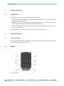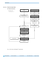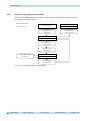
1
AG25, AG26 Actuator with User manual 305/15 interface Table of contents 1 General Information .................................................................................................. 9 1.1 Documentation ........................................................................................................9 2 Display and controls .................................................................................................. 9 2.1 General Information ..................................................................................................9 2.2 Displays ..................................................................................................................9 2.2.1 Ethernet module statuses ..................................................................................... 10 2.2.1.1 Module status LED 1......................................................................................... 10 2.2.1.2 Link/Activity LED 2, 3 ...................................................................................... 10 2.2.1.3 Network status LED 4 ....................................................................................... 11 2.2.2 Drive status........................................................................................................ 11 2.2.2.1 Status LED 5 ................................................................................................... 11 2.2.2.2 Status LEDs 6, 7 .............................................................................................. 11 2.2.2.3 Status LED 8 ................................................................................................... 11 2.3 Controls ................................................................................................................ 12 2.3.1 Control keys ....................................................................................................... 12 2.3.2 DIP switch: ........................................................................................................ 13 3 Digital inputs and outputs ....................................................................................... 13 3.1 Examples of digital input configurations .................................................................... 14 3.2 Example of digital output configuration ..................................................................... 15 4 Functional description ............................................................................................. 16 4.1 Control of the drive ................................................................................................ 16 4.1.1 Operating modes ................................................................................................. 16 4.1.1.1 Positioning mode ............................................................................................ 16 4.1.1.1.1 Loop positioning.......................................................................................... 17 4.1.1.2 Inching mode ................................................................................................. 18 4.1.1.2.1 Inching mode 1 ........................................................................................... 18 4.1.1.2.2 Inching mode 2 ........................................................................................... 19 4.1.1.3 Rotational speed mode ..................................................................................... 19 4.1.1.4 Position Control Mode ...................................................................................... 20 4.1.1.4.1 Examples of configuration of the digital inputs for the PCM ............................... 21 4.1.2 Current limiting .................................................................................................. 22 4.1.3 Limit switch ....................................................................................................... 22 4.1.3.1 Example of limit switch configuration................................................................. 23 4.1.3.2 Arrangement of the limit switches ..................................................................... 23 5 Calibration .............................................................................................................. 24 6 External transmission .............................................................................................. 24 7 Warnings / Errors..................................................................................................... 25 7.1 Warnings ............................................................................................................... 25 7.2 Errors.................................................................................................................... 25 AG25, AG26 Date: 11.08.2015 Art. No. 87613 Mod. status 305/15 Page 2 of 102 7.2.1 Error codes ......................................................................................................... 26 8 EtherNet/IP™ .......................................................................................................... 27 8.1 Description ............................................................................................................ 27 8.1.1 I/O Messages...................................................................................................... 27 8.1.2 Explicit Messages ................................................................................................ 27 8.1.3 ADI Object (Class A2h)......................................................................................... 28 8.2 Overview of parameters ........................................................................................... 29 8.2.1 Parameter description .......................................................................................... 31 8.2.1.1 Digital Outputs Control ..................................................................................... 31 8.2.1.2 Control Word................................................................................................... 32 8.2.1.2.1 Control word: Positioning mode (master slave) ............................................ 32 8.2.1.2.2 Flow chart: Operating mode: Positioning mode ................................................. 33 8.2.1.2.3 Control word Operating mode: Speed mode ...................................................... 34 8.2.1.2.4 Flow chart: Speed mode ................................................................................ 35 8.2.1.3 Target Value ................................................................................................... 36 8.2.1.4 Digital Inputs State ......................................................................................... 36 8.2.1.5 Status Word .................................................................................................... 36 8.2.1.5.1 Status word: Positioning mode (slave master) .............................................. 37 8.2.1.5.2 Status word: Speed mode .............................................................................. 38 8.2.1.6 Actual Value ................................................................................................... 39 8.2.1.7 LED Functionality ............................................................................................ 39 8.2.1.8 Service Interface Baud Rate .............................................................................. 41 8.2.1.9 Digital Output 1 Functionality ........................................................................... 41 8.2.1.10 Digital Output Functionalities State ................................................................... 42 8.2.1.11 Digital Outputs Polarity .................................................................................... 42 8.2.1.12 Digital Input 1 Functionality ............................................................................. 43 8.2.1.13 Digital Input 2 Functionality ............................................................................. 43 8.2.1.14 Digital Input 3 Functionality ............................................................................. 44 8.2.1.15 Digital Input 4 Functionality ............................................................................. 44 8.2.1.16 Digital Input Functionalities State ..................................................................... 45 8.2.1.17 Digital Inputs Polarity ...................................................................................... 46 8.2.1.18 Controller Parameter P ..................................................................................... 46 8.2.1.19 Controller Parameter I ...................................................................................... 46 8.2.1.20 Controller Parameter D ..................................................................................... 47 8.2.1.21 A-Pos............................................................................................................. 47 8.2.1.22 V-Pos ............................................................................................................. 47 8.2.1.23 D-Pos............................................................................................................. 48 8.2.1.24 A-Rot ............................................................................................................. 48 8.2.1.25 A-Inch ........................................................................................................... 48 8.2.1.26 V-Inch ........................................................................................................... 49 8.2.1.27 Pos Window .................................................................................................... 49 8.2.1.28 Gear Ratio Numerator ....................................................................................... 49 8.2.1.29 Gear Ratio Denominator.................................................................................... 50 AG25, AG26 Date: 11.08.2015 Art. No. 87613 Mod. status 305/15 Page 3 of 102 8.2.1.30 8.2.1.31 8.2.1.32 8.2.1.33 8.2.1.34 8.2.1.35 8.2.1.36 8.2.1.37 8.2.1.38 8.2.1.39 8.2.1.40 8.2.1.41 8.2.1.42 8.2.1.43 8.2.1.44 8.2.1.45 8.2.1.46 8.2.1.47 8.2.1.48 8.2.1.49 8.2.1.50 8.2.1.51 8.2.1.52 8.2.1.53 8.2.1.54 8.2.1.55 8.2.1.56 8.2.1.57 8.2.1.58 8.2.1.59 8.2.1.60 8.2.1.61 8.2.1.62 8.2.1.63 8.2.1.64 8.2.1.65 8.2.1.66 8.2.1.67 8.2.1.68 8.2.1.69 8.2.1.70 8.2.1.71 8.2.1.72 8.2.1.73 AG25, AG26 Spindle Pitch .................................................................................................. 50 Calibration Value ............................................................................................. 50 Software Limit 1 .............................................................................................. 51 Software Limit 2 .............................................................................................. 51 Delta Inch ...................................................................................................... 52 Sense of Rotation ............................................................................................ 52 Pos Type ........................................................................................................ 53 Operating Mode ............................................................................................... 53 Inching 2 Stop Mode........................................................................................ 54 Inpos Mode .................................................................................................... 54 Loop Length ................................................................................................... 55 Contouring Error Limit ...................................................................................... 55 Current Limiting .............................................................................................. 56 Inching 2 Offset .............................................................................................. 56 Inching 2 Acceleration Type .............................................................................. 57 Offset Value .................................................................................................... 57 PCM Position 1 ................................................................................................ 58 PCM Position 2 ................................................................................................ 58 PCM Position 3 ................................................................................................ 58 PCM Position 4 ................................................................................................ 59 PCM Position 5 ................................................................................................ 59 PCM Position 6 ................................................................................................ 59 PCM Position 7 ................................................................................................ 60 PCM Acceleration 1 .......................................................................................... 60 PCM Acceleration 2 .......................................................................................... 60 PCM Acceleration 3 .......................................................................................... 61 PCM Acceleration 4 .......................................................................................... 61 PCM Acceleration 5 .......................................................................................... 61 PCM Acceleration 6 .......................................................................................... 62 PCM Acceleration 7 .......................................................................................... 62 PCM Velocity 1 ................................................................................................ 62 PCM Velocity 2 ................................................................................................ 63 PCM Velocity 3 ................................................................................................ 63 PCM Velocity 4 ................................................................................................ 63 PCM Velocity 5 ................................................................................................ 64 PCM Velocity 6 ................................................................................................ 64 PCM Velocity 7 ................................................................................................ 64 PCM Deceleration 1 .......................................................................................... 65 PCM Deceleration 2 .......................................................................................... 65 PCM Deceleration 3 .......................................................................................... 66 PCM Deceleration 4 .......................................................................................... 66 PCM Deceleration 5 .......................................................................................... 67 PCM Deceleration 6 .......................................................................................... 67 PCM Deceleration 7 .......................................................................................... 68 Date: 11.08.2015 Art. No. 87613 Mod. status 305/15 Page 4 of 102 8.2.1.74 Output Stage Temperature ................................................................................ 68 8.2.1.75 Voltage of Control ........................................................................................... 68 8.2.1.76 Voltage of Output Stage ................................................................................... 69 8.2.1.77 Voltage of Battery ........................................................................................... 69 8.2.1.78 Motor Current.................................................................................................. 69 8.2.1.79 Actual Position ............................................................................................... 69 8.2.1.80 Actual Rotational Speed ................................................................................... 70 8.2.1.81 Serial Number ................................................................................................. 70 8.2.1.82 Production Date .............................................................................................. 70 8.2.1.83 SW Motor Controller ......................................................................................... 70 8.2.1.84 Gear Reduction................................................................................................ 71 8.2.1.85 System Status Word ......................................................................................... 71 8.2.1.86 Encoder Resolution .......................................................................................... 73 8.2.1.87 Device ID ....................................................................................................... 73 8.2.1.88 Number of Errors ............................................................................................. 74 8.2.1.89 Error Number 1 ................................................................................................ 74 8.2.1.90 Error Number 2 ................................................................................................ 74 8.2.1.91 Error Number 3 ................................................................................................ 74 8.2.1.92 Error Number 4 ................................................................................................ 75 8.2.1.93 Error Number 5 ................................................................................................ 75 8.2.1.94 Error Number 6 ................................................................................................ 75 8.2.1.95 Error Number 7 ................................................................................................ 75 8.2.1.96 Error Number 8 ................................................................................................ 76 8.2.1.97 Error Number 9 ................................................................................................ 76 8.2.1.98 Error Number 10 .............................................................................................. 76 8.2.1.99 S-Command .................................................................................................... 77 8.3 CIP objects ............................................................................................................ 77 8.3.1 Identity Object (Class 01h) ................................................................................... 78 8.3.1.1 Class attributes of the Identity Object ................................................................ 78 8.3.1.2 Instance attributes of the Identity Object ........................................................... 79 8.3.1.3 Status ............................................................................................................ 80 8.3.1.4 Reset service of the Identity Object ................................................................... 80 9 Service protocol....................................................................................................... 81 9.1 General Information ................................................................................................ 81 9.1.1 Communication ................................................................................................... 81 9.1.2 Settings............................................................................................................. 81 9.1.3 ASCII commands ................................................................................................. 81 9.1.4 Responses .......................................................................................................... 81 9.2 Overview of parameters ........................................................................................... 82 9.3 Parameters ............................................................................................................ 82 9.3.1 Positioning ........................................................................................................ 82 9.3.1.1 Target Value ................................................................................................... 82 9.3.1.2 Actual Position ............................................................................................... 82 AG25, AG26 Date: 11.08.2015 Art. No. 87613 Mod. status 305/15 Page 5 of 102 9.3.1.3 Actual Rotational Speed ................................................................................... 82 9.3.1.4 Calibration Value ............................................................................................. 83 9.3.1.5 Loop Length ................................................................................................... 83 9.3.1.6 Offset Value .................................................................................................... 83 9.3.1.7 Pos Type ........................................................................................................ 83 9.3.1.8 Pos Window .................................................................................................... 83 9.3.1.9 Sense of Rotation ............................................................................................ 84 9.3.1.10 Spindle Pitch .................................................................................................. 84 9.3.2 Actuator ............................................................................................................ 84 9.3.2.1 A-Pos............................................................................................................. 84 9.3.2.2 V-Pos ............................................................................................................. 84 9.3.2.3 D-Pos............................................................................................................. 84 9.3.2.4 A-Rot ............................................................................................................. 84 9.3.2.5 A-Inch ........................................................................................................... 85 9.3.2.6 V-Inch ........................................................................................................... 85 9.3.2.7 Gear Ratio Denominator.................................................................................... 85 9.3.2.8 Gear Ratio Numerator ....................................................................................... 85 9.3.3 Limiting values ................................................................................................... 85 9.3.3.1 Software Limit 1 .............................................................................................. 85 9.3.3.2 Software Limit 2 .............................................................................................. 85 9.3.3.3 Current Limiting .............................................................................................. 86 9.3.3.4 Contouring Error Limit ...................................................................................... 86 9.3.4 Options ............................................................................................................. 86 9.3.4.1 Operating Mode ............................................................................................... 86 9.3.4.2 Inpos Mode .................................................................................................... 86 9.3.4.3 Delta Inch ...................................................................................................... 86 9.3.4.4 Inching 2 Acceleration Type .............................................................................. 86 9.3.4.5 Inching 2 Offset .............................................................................................. 87 9.3.4.6 Inching 2 Stop Mode........................................................................................ 87 9.3.4.7 LED Functionality@ ......................................................................................... 87 9.3.4.8 Service Interface Baud rate ............................................................................... 87 9.3.5 Controller parameter ............................................................................................ 87 9.3.5.1 Controller Parameter P ..................................................................................... 87 9.3.5.2 Controller Parameter I ...................................................................................... 87 9.3.5.3 Controller Parameter D ..................................................................................... 88 9.3.6 Device information .............................................................................................. 88 9.3.6.1 Motor Current.................................................................................................. 88 9.3.6.2 Output Stage Temperature ................................................................................ 88 9.3.6.3 Voltage of Control ........................................................................................... 88 9.3.6.4 Voltage of Output Stage ................................................................................... 88 9.3.6.5 Voltage of Battery ........................................................................................... 88 9.3.6.6 Flag Register................................................................................................... 89 9.3.6.7 System Status Word ......................................................................................... 89 9.3.6.8 Device Type .................................................................................................... 89 AG25, AG26 Date: 11.08.2015 Art. No. 87613 Mod. status 305/15 Page 6 of 102 9.3.6.9 Gear Reduction................................................................................................ 89 9.3.6.10 Motor Type ..................................................................................................... 89 9.3.6.11 Network Type .................................................................................................. 90 9.3.6.12 Production Date .............................................................................................. 90 9.3.6.13 Serial Number ................................................................................................. 90 9.3.6.14 SW Ethernet Module ......................................................................................... 90 9.3.6.15 SW Motor Controller ......................................................................................... 90 9.3.7 Digital input/output ............................................................................................ 90 9.3.7.1 Digital Input 1 Functionality ............................................................................. 90 9.3.7.2 Digital Input 2 Functionality ............................................................................. 91 9.3.7.3 Digital Input 3 Functionality ............................................................................. 91 9.3.7.4 Digital Input 4 Functionality ............................................................................. 91 9.3.7.5 Digital Input Functionalities State ..................................................................... 91 9.3.7.6 Digital Inputs Polarity ...................................................................................... 91 9.3.7.7 Digital Inputs State ......................................................................................... 91 9.3.7.8 Digital Output 1 Functionality ........................................................................... 92 9.3.7.9 Digital Outputs Control ..................................................................................... 92 9.3.7.10 Digital Output Functionalities State ................................................................... 92 9.3.7.11 Digital Outputs Polarity .................................................................................... 92 9.3.8 Error memory ...................................................................................................... 92 9.3.8.1 Number of Errors ............................................................................................. 92 9.3.8.2 Error Number 1 ................................................................................................ 92 9.3.8.3 Error Number 2 ................................................................................................ 93 9.3.8.4 Error Number 3 ................................................................................................ 93 9.3.8.5 Error Number 4 ................................................................................................ 93 9.3.8.6 Error Number 5 ................................................................................................ 93 9.3.8.7 Error Number 6 ................................................................................................ 93 9.3.8.8 Error Number 7 ................................................................................................ 93 9.3.8.9 Error Number 8 ................................................................................................ 94 9.3.8.10 Error Number 9 ................................................................................................ 94 9.3.8.11 Error Number 10 .............................................................................................. 94 9.4 Commands ............................................................................................................. 94 9.4.1 Start travel job ................................................................................................... 94 9.4.2 start of inching mode 1 ....................................................................................... 94 9.4.3 Start inching mode 2 positive travel direction ......................................................... 94 9.4.4 Start inching mode 2 negative travel direction ........................................................ 95 9.4.5 Cancel current travel job in positioning mode ......................................................... 95 9.4.6 Motor stop fast ................................................................................................... 95 9.4.7 Motor stop ......................................................................................................... 95 9.4.8 enable motor ...................................................................................................... 95 9.4.9 Factory setting: all parameters .............................................................................. 95 9.4.10 Factory setting: Standard parameter ...................................................................... 96 9.4.11 Factory setting: Controller parameter ..................................................................... 96 9.4.12 Acknowledge error............................................................................................... 96 AG25, AG26 Date: 11.08.2015 Art. No. 87613 Mod. status 305/15 Page 7 of 102 9.4.13 Calibrate ............................................................................................................ 96 9.4.14 Delete error memory ............................................................................................ 96 9.4.15 Software Reset.................................................................................................... 96 9.5 Flow charts ............................................................................................................ 97 9.5.1 Flow chart: Operating mode: Positioning mode ........................................................ 97 9.5.2 Flow chart: Operating mode: Speed mode ............................................................... 98 9.6 Error number encoding ............................................................................................ 99 9.7 Examples ............................................................................................................... 99 9.7.1 Write and read setpoint +500................................................................................ 99 9.7.2 Start travel job ................................................................................................... 99 9.8 ASCII command structure ...................................................................................... 100 10 Block diagram ........................................................................................................101 11 Web server .............................................................................................................102 AG25, AG26 Date: 11.08.2015 Art. No. 87613 Mod. status 305/15 Page 8 of 102 General Information 1 General Information 1.1 Documentation The following documents are associated with this document: Product data sheet, describes the technical data, the dimensions, the pin assignment, the accessories and the order key. Installation instructions, describe the mechanical and electrical installation with all safetyrelevant conditions and the associated technical specifications. User manual describing the migration of the actuator into an Industrial Ethernet network and its commissioning. These documents can also be found at http://www.siko-global.com/p/AG25. 2 Display and controls 2.1 General Information The drive has various LEDs that indicate the statuses of the drive and of the Ethernet module. The controls are located below the cover. 2.2 Displays Fig.. 1: Displays AG25, AG26 Date: 16.06.2014 Art. No. 87613 Mod. status 305/15 Page 9 of 102 Display and controls 2.2.1 Ethernet module statuses The , , , LEDs inform about the statuses of the Ethernet module. The Ethernet module LEDs' functions are permanently defined and cannot be changed. LED 1 2 3 4 2.2.1.1 Description Module status LED Link/Activity LED Link/Activity LED Network status LED Module status LED 1 A test sequence is executed on this LED after switching on the device. LED state Off Green Green, flashing Red Red, flashing 2.2.1.2 Description No operating voltage Control via scanner Not configured or scanner inactive Serious error Correctable error. The module has been configured but the stored parameters differ from the parameters presently used. Link/Activity LED 2, 3 LED state Off Green Green, flashing Yellow Yellow, flashing AG25, AG26 Description No connection, no activity Connection (100 Mbit/s) established Activity (100 Mbit/s) Connection (10 Mbit/s) established Activity (10 Mbit/s) Date: 11.08.2015 Art. No. 87613 Mod. status 305/15 Page 10 of 102 Display and controls 2.2.1.3 Network status LED 4 A test sequence is executed on this LED after switching on the device. LED state Off Green Green, flashing Red Red, flashing 2.2.2 Description No operating voltage or no IP address On-line, one or multiple connections established (CIP Class 1 or 3) On-line, no connection established Double IP address, fatal error On-line, one or multiple connections timeout (CIP Class 1 or 3) Drive status With factory setting, the , , , inform about the drive's status. The functions of the drive status LEDs can be configured. 2.2.2.1 Status LED 5 LED statuses valid with factory setting. LED state Green Red, flashing Off 2.2.2.2 Description Operating voltage applied to control, no fault Operating voltage applied to control, active fault Operating voltage of control missing Status LEDs 6, 7 LED statuses valid with factory setting. LED state Off 2.2.2.3 Description No function Status LED 8 If the actual value is unequal after switching on the module and if it is outside the programmed positioning window, then the LED status is “red” or “red, flashing” due to volatile storage of the setpoint. The setpoint is initialized with the value 0 after switching on. AG25, AG26 Date: 11.08.2015 Art. No. 87613 Mod. status 305/15 Page 11 of 102 Display and controls LED statuses valid with factory setting. LED state Green Description Actuator is within the programmed positioning window. Operating voltage of the output stage is applied. green, flashing Actuator is within the programmed position window. Operating voltage of the output stage missing. red Actuator is outside the programmed positioning window. Operating voltage of the output stage is applied. red, flashing Actuator is outside the programmed positioning window. Operating voltage of the output stage missing. off Operating voltage of control missing. 2.3 Controls Fig. 2: Controls 2.3.1 Control keys Manual setup operation is only available if there is no process data exchange going on. Manual setup mode (corresponding to inching mode 2) can be started by means of the control keys. This enables actuator movement without a superordinate control. Key : Inching mode 2 in e direction Key : Inching mode 2 in i direction AG25, AG26 Date: 11.08.2015 Art. No. 87613 Mod. status 305/15 Page 12 of 102 Digital inputs and outputs 2.3.2 DIP switch: The DIP switch is only read when the control's operating voltage is switched on. Therefore, any change takes effect only after power-on reset of the control's operating voltage. Switch SW1-SW8 Assignment Setting of the IP address in binary format. 0 = DHCP/BOOTP 1 = Don’t use 2 … 254 = setting of the last byte of the IP address 192.168.1.XXX 255 = DHCP/BOOTP No function, always off SW9-SW10 If required, you can use DIP switches SW1-SW8 to set the last byte of the IP address in binary format. With the value zero set, the settings for IP address, subnet mask, and standard gateway can be obtained from a DHCP server. The following applies to a value set between 2 and 254: 3 IP address Subnet mask Standard gateway DHCP Range from 192.168.1.2 to 192.168.1.254 255.255.255.0 192.168.1.1 Deactivated SW1 OFF ON SW2 OFF OFF SW3 OFF OFF SW4 OFF OFF SW5 OFF OFF SW6 OFF OFF SW7 OFF OFF SW8 OFF OFF OFF … OFF ON ON … ON ON OFF … ON ON OFF … ON ON OFF … ON ON OFF … ON ON OFF … ON ON OFF … ON ON IP DHCP/BOOTP 192.168.1.1 Don´t use, address is occupied by standard gateway. 192.168.1.2 … 192.168.1.254 DHCP/BOOTP Digital inputs and outputs The actuator has four configurable digital inputs and one configurable digital output. Function and switching behavior can be set. No function has been assigned to the digital inputs in the factory setting. The logical status of the digital inputs is mapped in the process data independent of the assigned function. If a function was assigned to the digital input, the functions' conditions of the digital inputs can be read in the register Digital Input Functionalities State (instance 1029). AG25, AG26 Date: 11.08.2015 Art. No. 87613 Mod. status 305/15 Page 13 of 102 Digital inputs and outputs With factory settings, the digital output can be actuated via the process data. If a function is assigned to the digital output, it is actuated via register Digital Output Functionalities State (instance 770). 3.1 Examples of digital input configurations The following configuration deviates from the factory setting and requires parameterization by the user. Digital input 1: Limit switch 1 (low-active) proximity switch DC PNP NC Digital input 2: Limit switch 2 (low-active) proximity switch DC PNP NC Digital input 3: Inching mode 2 positive travel direction (high-active) pushbutton Digital input 4: Inching mode 2 negative travel direction (high-active) pushbutton Digital Input Functionalities State (instance 1029) Digital input 1 XOR Digital Inputs Polarity (instance 1030), bit 0 = 1 Digital Input 1 Functionality (instance 1025), value = 1 Bit 0 Digital input 2 XOR Digital Inputs Polarity (instance 1030), bit 1 = 1 Digital Input 2 Functionality (instance 1026), value = 2 Bit 1 Digital input 3 XOR Digital Inputs Polarity (instance 1030), bit 2 = 0 Digital Input 3 Functionality (instance 1027), value = 3 Bit 2 Digital input 4 XOR Digital Inputs Polarity (instance 1030), bit 3 = 0 Digital Input 4 Functionality (instance 1028), value = 4 Bit 3 : Bit 31 Fig. 3: Examples of digital input configurations AG25, AG26 Date: 11.08.2015 Art. No. 87613 Mod. status 305/15 Page 14 of 102 Digital inputs and outputs 3.2 Example of digital output configuration Digital output 1: Inpos (high-active) Digital Output Functionalities State Instance 770 Bit 0 Digital Output 1 Functionality (instance 769), value = 2 XOR Digital Outputs Polarity (instance 771), bit 0 = 0 Digital output 1: : Bit 31 Fig. 4: Example of digital output configuration AG25, AG26 Date: 11.08.2015 Art. No. 87613 Mod. status 305/15 Page 15 of 102 Functional description 4 Functional description 4.1 Control of the drive The drive can be moved manually via the keys or digital inputs without upstream control. The drive can be controlled and configured in the bus operating mode and via the service interface. 4.1.1 Operating modes The following operating modes are distinguished: positioning mode and speed mode. In the positioning mode there is the additional option of traveling in the inching mode. The position control mode can be started via the digital inputs independent of the chosen operating mode. 4.1.1.1 Positioning mode In the positioning mode, positioning to the specified set point is executed by means of a ramp function (see Fig. 5: Ramp travel, direct positioning mode) calculated on the basis of the actual position as well as the programmed controller parameters P (proportional factor), I (integral factor), D (differential factor), acceleration and speed. Upon activation of the travel job, the actuator accelerates to the specified speed with the acceleration programmed. The measure of delay to the setpoint is defined by the parameter A-Pos (instance 1540) as well. Alternately, a value deviating from acceleration can be chosen for delay by means of parameter D-Pos (instance 1542). Changing controller parameters during a positioning process does not influence the current positioning operation. Velocity V-Pos (instance 1541) A-Pos (instance 1540) A-Pos (instance 1540) D-Pos (instance 1542) target position Start position Time Fig. 5: Ramp travel, direct positioning mode AG25, AG26 Date: 11.08.2015 Art. No. 87613 Mod. status 305/15 Page 16 of 102 Functional description The status word indicates whether the actual position is within the window defined by parameter Pos Window (instance 1546). Upon reaching the programmed window via parameter Inpos Mode (instance 1558), you can define the behavior of the actuator. Travel range Lower limit Software Limit 2 (instance 1552) -10 +10 Software Limit 1 (instance 1551) Travel range Upper limit 0 - + Pos Window (instance 1546) Inpos Mode (instance 1558) Fig. 6: Positioning mode The max. travel range depends on transmission and scaling. The number of revolutions specified in the product data sheet must not be exceeded. 4.1.1.1.1 Loop positioning A travel order will not be executed if loop positioning would exceed the limiting values specified by parameters Software Limit 1 (instance 1551) and Software Limit 2 (instance 1552) although the setpoint is within the limiting values. If the actuator is operated on a spindle or an additional transmission, the spindle or external transmission backlash can be compensated by means of loop positioning. In this case, traveling to the target value is always from the same direction. This travel direction can be determined via parameter Pos Type (instance 1555). Loop length is set via parameter Loop Length (instance 1559). Example: The direction from which every target position shall be driven to is positive. Case 1 new position is greater than actual position: Direct travel to required position Case 2 new position is smaller than actual position: The actuator drives beyond the target position by the loop length; afterwards, the set point is approached in positive direction. AG25, AG26 Date: 11.08.2015 Art. No. 87613 Mod. status 305/15 Page 17 of 102 Functional description Positioning: loop + Loop Length (instance 1559) Positioning in positive direction Positioning in negative direction - + Setpoint Fig. 7: Loop+ positioning 4.1.1.2 Inching mode There is no compensation for spindle backlash (loop positioning) in this operating mode. Inching mode is enabled in the positioning mode only. You can program via parameters acceleration as well as speed in the inching mode. 4.1.1.2.1 Inching mode 1 If the Spindle pitch parameter is programmed to zero, then the traveling distance occurs by increments. If Spindle pitch is unequal zero, then the information of the Delta Tipp parameter refers to the travel distance in 1/100 mm. If the actual position is outside the programmed limiting values, then traveling from this position in the respective direction must be performed by means of inching mode 1 or 2! The drive travels once from the current actual position by the value Delta Inch (instance 1553) depending on the mathematical sign of the value entered. Delta Inch < 0: negative travel direction Delta Inch > 0: positive travel direction Reaching of the target position will be signaled accordingly. The digital input can be configured for starting inching mode 1. The following conditions must be met for enabling the start of inching modes 1 and 2: Supply voltage of the output stage is applied. Operation enabled Drive stands still AG25, AG26 Date: 11.08.2015 Art. No. 87613 Mod. status 305/15 Page 18 of 102 Functional description 4.1.1.2.2 Inching mode 2 The actuator travels from the current position as long as the relevant command is active. You can influence the inching speed via two parameters and it will be calculated in the actuator as illustrated in the example below: V-Inch (instance 1545) = 10 rpm (can only be changed in the idle state) Inching 2 Offset (instance 1562) = 85 % (can be changed during inching operation) The resulting inching speed in this example will be: Inching speed= v - Tipp * Offset inching 2 = 10 rpm * 85 % = 9 rpm Results are always rounded to integers. Minimum speed is 1 rpm. 4.1.1.3 Rotational speed mode Limits 1 + 2 are inactivated in this operational mode. Exceeding the resolution of the absolute encoder results in a jump of the actual position. With the set point enabled, the actuator when in the rotational speed mode accelerates to the target speed and maintains this speed until the set point is disabled or a different target speed specified. Speed is adjusted immediately to the new value when the rotational target speed is changed. The arithmetical sign of the set point determines the travel direction in the rotational speed mode. Velocity Target speed (set point) Disable operation Disable target value or set point = 0 A-Rot (instance 1543) 'Stop' Set point enabled Time Fig. 8: Ramp speed mode AG25, AG26 Date: 11.08.2015 Art. No. 87613 Mod. status 305/15 Page 19 of 102 Functional description The following conditions must be met for enabling the start of the rotational speed mode: Supply voltage of the output stage is applied. Operation enabled Drive stands still 4.1.1.4 Position Control Mode Via the control word in the process data, the superordinate control can cancel travel jobs started by the position control mode. For this purpose, a negative flank must be created on bits OFF1, OFF2, or OFF3 in the control word. Conversely, the PCM mode cannot cancel a travel order initiated via the superordinate control. The position control mode enables travel data sets to be called via the digital inputs. A total of 7 travel data sets can be saved. The use of the position control mode requires previous configuration of the digital inputs. The desired travel data set can be selected via PCM inputs 1 to 3 in binary addressing. Travel data set 0 does not exist. AG25, AG26 Date: 11.08.2015 Art. No. 87613 Mod. status 305/15 Page 20 of 102 Functional description 4.1.1.4.1 Examples of configuration of the digital inputs for the PCM Digital input 1: PCM Start (high-active) Digital input 2: PCM input 1 (high-active) Digital input 3: PCM input 2 (high-active) Digital input 4: PCM input 3 (high-active) Digital Input Functionalities State instance 1029 Bit 0 : Digital input 1 XOR Digital Inputs Polarity instance 1030, bit 0 = 0 Digital Input 1 Functionality instance 1025, value = 8 Bit 7 Digital input 2 XOR Digital Inputs Polarity instance 1030, bit 1 = 0 Digital Input 2 Functionality instance 1026, value = 9 Bit 8 Digital input 3 XOR Digital Inputs Polarity instance 1030, bit 2 = 0 Digital Input 3 Functionality instance 1027, value = 10 Bit 9 Digital input 4 XOR Digital Inputs Polarity instance 1030, bit 3 = 0 Digital Input 4 Functionality instance 1028, value = 11 Bit 10 : Bit 31 Fig. 9: Examples of configuration of the digital inputs for the PCM Example of the parameter set of travel data set no. 3 Parameter PCM Position 3 PCM Acceleration 3 PCM Velocity 3 PCM Deceleration 3 Instance 2340 2372 2404 2436 After applying the coding to the inputs, the desired travel job can be started by a positive flank on the PCM Start input. Resetting the PCM Start input during an active positioning process will result in cancellation of the travel job but the drive will continue to be controlled. AG25, AG26 Date: 11.08.2015 Art. No. 87613 Mod. status 305/15 Page 21 of 102 Functional description An example of calling travel data set no. 3 is shown below Step 1: Create number of travel data set Input PCM Start PCM input 1 PCM input 2 PCM input 3 State 0 1 1 0 Step 2: Start the positioning job Input PCM Start PCM input 1 PCM input 2 PCM input 3 4.1.2 State 0/1 1 1 0 Current limiting The actual motor current cannot be indicated by measuring the supply current. With cycled output stages, the supply current does not correspond to the motor current. Actual motor current can be read via the interface. The current limit is set via Parameter Current Limiting (instance 1561), which serves primarily for protecting the drive against overload. With default set, nominal speed indicated on the product data sheet is achieved. Actuator overload results in limiting the motor current to the set value. As a consequence, the actuator cannot maintain the speed set, the contouring error increases. The actuator changes to the error status if the contouring error exceeds the contouring error limit defined by the Contouring Error Limit parameter (instance 1560): contouring error. 4.1.3 Limit switch Two digital inputs must be configured correspondingly if the limit switch function is to be used AG25, AG26 Date: 11.08.2015 Art. No. 87613 Mod. status 305/15 Page 22 of 102 Functional description 4.1.3.1 Example of limit switch configuration Exemplary configuration for the connection of proximity switches DC PNP NC. Digital Input Functionalities State Instance 1029 Digital input 1 XOR Digital Inputs Polarity instance 1030, bit 0 = 1 Digital Input 1 Functionality instance 1025, value = 1 Bit 0 Digital input 2 XOR Digital Inputs Polarity instance 1030, bit 1 = 1 Digital Input 2 Functionality instance 1026, value = 2 Bit 1 : Bit 31 Fig. 10: Example of limit switch configuration 4.1.3.2 Arrangement of the limit switches The arrangement of the limit switches is independent of the configured sense of rotation according to the following pattern: limit switch 2: limit switch 1: Fig. 11: Arrangement of the limit switches AG25, AG26 Date: 11.08.2015 Art. No. 87613 Mod. status 305/15 Page 23 of 102 Calibration 5 Calibration Calibration is only possible when no travel job is active! Two steps are required for executing calibration: Write calibration value: see Calibration Value (instance 1550) Execute calibration (software command or calibration input) Calibration can be initiated by writing the value 7 to parameter S-Command (instance 3073). Alternately, a digital input can be configured as calibration input as well. Since the measuring system is an absolute system, calibration is necessary only once with commissioning. With calibration, the calibration value is adopted for calculation of the position value. The following equation is applied in case of calibration: Position value = 0 + Calibration Value (instance 1550) + Offset Value (instance 1564) 6 External transmission If external transmission is used, a factor can be programmed via the parameters Gear Ratio Numerator (instance 1547) and Gear Ratio Denominator (instance 1548) in order to include the transmission ratio in position sensing. Example (see Fig. 12: External transmission): The actuator is operated on a transmission with reduction of 5:1. For this purpose, the Gear Ratio Numerator and Gear Ratio Denominator must be programmed as follows: Parameter Gear Ratio Numerator = 5 Parameter Gear Ratio Denominator = 1 5 revolutions External transmission 5:1 1 revolution M Transmission output Internal transmission Fig. 12: External transmission Input of an odd transmission reduction value is possible according to the following example: Transmission reduction = 3.78 Parameter Gear Ratio Numerator = 378 Parameter Gear Ratio Denominator = 100 AG25, AG26 Date: 11.08.2015 Art. No. 87613 Mod. status 305/15 Page 24 of 102 Warnings / Errors 7 Warnings / Errors 7.1 Warnings Warnings do not influence the operation of the actuator. Warnings disappear after removing the cause. Possible warnings: Battery voltage for absolute encoder is below limit exchange battery within the next 6 months. Current limiting active 7.2 Errors Errors cause an immediate stop of drive movement. Errors are indicated via the drive status LEDs. The error bit is set in the status word. The error messages are entered in the error memory in the order of their detection. The last 10 error messages are displayed when the error memory is full. The cause of error can be tracked down with the help of the error codes. AG25, AG26 Date: 11.08.2015 Art. No. 87613 Mod. status 305/15 Page 25 of 102 Warnings / Errors 7.2.1 Error codes If the error cannot be acknowledged after removal of the cause of error and the error persists after power-on reset, then the drive must be inspected in the factory. Error code 0x00 0x06 0x07 0x08 0x09 0x0A 0x0B 0x0C 0x0D 0x0F 0x10 0x13 0x14 0x15 0x16 Fault No error Low battery voltage: empty battery, replace battery bonding error, check battery bonding wrong battery type inserted, insert correct battery type Low control electronics voltage check control operating voltage Control electronics overvoltage check control operating voltage Power electronics overvoltage check output stage operating voltage Output stage excess temperature reduce ambient temperature reduce load Contouring error reduce load reduce acceleration reduce speed Output shaft blocked disengage shaft Power electronics not supplied check output stage operating voltage SIN COS monitoring shield from stray magnetic fields check EMC measures EEPROM queue overrun internal error EEPROM check sum reset parameters to factory settings Ethernet module watchdog internal error Ethernet module in the ERROR status while travel job is active internal error Ethernet module in the EXCEPTION status internal error, power-on reset necessary Table 1: Error codes AG25, AG26 Date: 11.08.2015 Art. No. 87613 Mod. status 305/15 Page 26 of 102 EtherNet/IP™ 8 EtherNet/IP™ 8.1 Description The drive has been designed as CIP Generic Device (Type 2Bh). 8.1.1 I/O Messages Cyclic process data exchange is via I/O messages (class-1 connection). Two assemblies are available, which contain a collection of parameters required for the control of the drive. Connection: Exclusive Owner Target (drive) Origin (master) Assembly Object (04h), instance 64h Instance 258 259 257 Description Status word Actual value Digital inputs state Type UNIT DINT USINT Origin (master) Target (drive) Assembly Object (04h), instance 96h Instance 2 3 1 8.1.2 Description Control word Target value Digital outputs control Type UNIT DINT USINT Explicit Messages Acyclic exchange of parameter data is via explicit messages (class-3 connection). The parameter values of the individual instances are accessed via class A2h, attribute 5. AG25, AG26 Date: 11.08.2015 Art. No. 87613 Mod. status 305/15 Page 27 of 102 EtherNet/IP™ 8.1.3 ADI Object (Class A2h) All drive parameters are contained in the Application Data Instance object. Every parameter corresponds to an instance in this class. Access to the parameters is via explicit messages. Class attributes of the ADI object Number 1 2 Access Get Get Name Revision Max instances 3 Get Number of instances Description Object revision index Maximum number of object instances in this class Number of object instances in this class Data type UINT UINT Description Parameter name (including length) Data type of the instance value Number of elements of the specified Data type Bit field describing the access authorization for this instance Bit Meaning: 0 set= Get access 1 set= Set access Instance value The maximum admissible parameter value The minimum admissible parameter value Standard value Data type SHORT_STRING UINT Instance attributes of the ADI object Number 1 Access Get Name Name 2 3 Get Get Data type Number of elements 4 Get 5 6 Get/Set Get Value Max. value 7 Get Min. value 8 Get Default value USINT USINT USINT defined by attribute 2 Access to the parameter values is via Get/Set Attribute Single, Attribute 5. AG25, AG26 Date: 11.08.2015 Art. No. 87613 Mod. status 305/15 Page 28 of 102 EtherNet/IP™ 8.2 Overview of parameters Instance 1 2 3 257 258 259 513 769 770 771 1025 1026 1027 1028 1029 1030 1537 1538 1539 1540 1541 1542 1543 1544 1545 1546 1547 1548 1549 1550 1551 1552 1553 1554 1555 1556 1557 1558 1559 AG25, AG26 Parameter name Digital Outputs Control Control Word Target Value Digital Inputs State Status Word Actual Value LED Functionality Digital Output 1 Functionality Digital Output Functionalities State Digital Outputs Polarity Digital Input 1 Functionality Digital Input 2 Functionality Digital Input 3 Functionality Digital Input 4 Functionality Digital Input Functionalities State Digital Inputs Polarity Controller Parameter P Controller Parameter I Controller Parameter D A-Pos V-Pos D-Pos A-Rot A-Inch V-Inch Pos Window Gear Ratio Numerator Gear Ratio Denominator Spindle Pitch Calibration Value Software Limit 1 Software Limit 2 Delta Inch Sense of Rotation Pos Type Operating Mode Inching 2 Stop Mode Inpos Mode Loop Length Date: 11.08.2015 Art. No. 87613 Page 31 32 32 36 36 37 39 41 42 42 43 43 44 44 45 46 46 46 47 47 47 48 48 48 49 49 49 50 50 50 51 51 52 52 53 53 54 54 55 Mod. status 305/15 Page 29 of 102 EtherNet/IP™ Instance 1560 1561 1562 1563 1564 2338 2339 2340 2341 2342 2343 2344 2370 2371 2372 2373 2374 2375 2376 2402 2403 2404 2405 2406 2407 2408 2434 2435 2436 2437 2438 2439 2440 2561 2562 2563 2564 2565 2566 2567 2568 2569 AG25, AG26 Parameter name Contouring Error Limit Current Limiting Inching 2 Offset Inching 2 Acceleration Type Offset PCM Position 1 PCM Position 2 PCM Position 3 PCM Position 4 PCM Position 5 PCM Position 6 PCM Position 7 PCM Acceleration 1 PCM Acceleration 2 PCM Acceleration 3 PCM Acceleration 4 PCM Acceleration 5 PCM Acceleration 6 PCM Acceleration 7 PCM Velocity 1 PCM Velocity 2 PCM Velocity 3 PCM Velocity 4 PCM Velocity 5 PCM Velocity 6 PCM Velocity 7 PCM Deceleration 1 PCM Deceleration 2 PCM Deceleration 3 PCM Deceleration 4 PCM Deceleration 5 PCM Deceleration 6 PCM Deceleration 7 Output Stage Temperature Voltage of Control Voltage of Output Stage Voltage of Battery Motor Current Actual Position Actual Rotational Speed Serial Number Production Date Date: 11.08.2015 Art. No. 87613 Page 55 56 56 57 57 58 58 58 59 59 59 60 60 60 61 61 61 62 62 62 63 63 63 64 64 64 65 65 66 66 67 67 68 68 68 69 69 69 69 70 70 70 Mod. status 305/15 Page 30 of 102 EtherNet/IP™ Instance 2570 2571 2572 2573 2817 2818 2819 2820 2821 2822 2823 2824 2825 2826 2827 3073 Parameter name SW Motor Controller Gear Reduction System Status Word Encoder Resolution Number of Errors Error Number 1 Error Number 2 Error Number 3 Error Number 4 Error Number 5 Error Number 6 Error Number 7 Error Number 8 Error Number 9 Error Number 10 S-Command 8.2.1 Parameter description 8.2.1.1 Digital Outputs Control Instance Description Access Data type Default EEPROM Value range Bit 0 1…7 AG25, AG26 Page 70 71 71 73 74 74 74 74 75 75 75 75 76 76 76 77 1 dec /1 hex Digital output control byte Get/Set (Component of process data) USINT No No USINT Description Digital output 1 Reserved, always 0 Date: 11.08.2015 Art. No. 87613 Mod. status 305/15 Page 31 of 102 EtherNet/IP™ 8.2.1.2 Control Word Instance Description Access Data type Default EEPROM Value range 2 dec /2 hex Control word Get/Set (Component of process data) UINT No No UINT 8.2.1.2.1 Control word: Positioning mode (master slave) Bit Bit 0 OFF1 (enable ) Bit 1 OFF2 (max. delay) Bit 2 OFF3 (progr. delay) Bit 3 Intermediate stop Bit 4 Start travel job Bit 5 Acknowledge error Bit 6 Inching mode 1 Bit 7 Inching mode 2 positive Bit 8 Inching mode 2 negative Bit 9 Bit 10 Relative positioning Bit 11 … 15 Description 0 = OFF1 active Current travel job is canceled. The actuator is activated. 1 = OFF1 inactive 0 = OFF2 active Current travel job is canceled. The actuator is decelerated with max. delay, the actuator continues to be controlled. 1 = OFF2 inactive 0 = OFF3 active Current travel job is canceled. The actuator is decelerated with programmed delay, the actuator continues to be controlled. 1 = OFF3 inactive 0 = no intermediate stop 1 = intermediate stop active Positive flank starts a travel job Positive flank acknowledges an error Afterwards, the actuator changes to the switch-lock state. 0 = no inching mode 1 If the travel job is not completed yet it will be canceled. 1 = inching operation 1 As long as this bit is set, the actuator travels the distance specified in parameter Delta Tipp. 0 = no inching mode 2 positive 1 = inching mode 2 positive The actuator travels in positive direction 0 = no inching mode 2 negative 1 = inching mode 2 negative The actuator travels in negative direction Reserved, always 0 0 = absolute positioning 1 = relative positioning Reserved, always 0 Table 2: Positioning mode control word AG25, AG26 Date: 11.08.2015 Art. No. 87613 Mod. status 305/15 Page 32 of 102 EtherNet/IP™ 8.2.1.2.2 Flow chart: Operating mode: Positioning mode CW = Control word SW = Status word Fault Start SW.7 = 1 x = bit can be ‘0‘ or ‘1‘ Acknowledge error CW.5 = 1 Supply voltage On Switch-lock CW = 0000 0000 0000 0000 SW.9 = 1 Disengage switch lock OFF1 CW.0 = 1/0 or OFF2 CW.1 = 1/0 or OFF3 CW.2 = 1/0 Inching 1/2 On CW = 0000 0000 0100 0111 or CW = 0000 0000 1000 0111 or CW = 0000 0001 0000 0111 Enable operation CW = 0000 0000 0000 0111 Cancel travel job Operation enabled SW = 0000 x001 00x0 xxx1 Inching 1/2 active SW = 000x x001 00x1 0001 Active travel job SW = 000x x101 01x1 0001 Inching Off CW = 0000 0000 0000 0111 Activate travel job CW = 0000 0000 0001 0111 Travel job finished Active travel job SW = 000x x101 01x1 0001 Intermediate stop Continue positioning CW.3 = 1 CW.3 = 0 Intermediate stop active SW = 0000 x101 01x0 0011 Fig. 13: Flow chart of EtherNet/IP™ positioning mode AG25, AG26 Date: 11.08.2015 Art. No. 87613 Mod. status 305/15 Page 33 of 102 EtherNet/IP™ 8.2.1.2.3 Control word Operating mode: Speed mode Bit Bit 0 OFF1 (enable ) Bit 1 OFF2 (max.delay) Bit 2 OFF3 (progr. delay) Bit 3 Bit 4 Start travel job Bit 5 Acknowledge error Bit 6 … 15 Description 0 = OFF1 active Current travel job is canceled. The actuator is activated. 1 = OFF1 inactive 0 = OFF2 active Current travel job is canceled. The actuator is decelerated with max. delay, the actuator continues to be controlled. 1 = OFF2 inactive 0 = OFF3 active Current travel job is canceled. The actuator is decelerated with prog. delay, the actuator continues to be controlled. 1 = OFF3 inactive Reserved, always 0 Positive flank starts a travel job Positive flank acknowledges an error Afterwards, the actuator changes to the switch-lock state. Reserved, always 0 Table 3: Control word speed mode SIKONETZ5 AG25, AG26 Date: 11.08.2015 Art. No. 87613 Mod. status 305/15 Page 34 of 102 EtherNet/IP™ 8.2.1.2.4 Flow chart: Speed mode CW = Control word Fault Start SW = Status word SW.7 = 1 x = Bit can be ‘0‘ or ‘1‘ CW.5 = 1 Operating voltage On Switch lock CW = 0000 0000 0000 0000 SW.9 = 1 Disengage switch lock OFF1 CW.0 = 1/0 or OFF2 CW.1 = 1/0 or OFF3 CW.2 = 1/0 Enable operation CW = 0000 0000 0000 0111 Cancel travel job Operation enabled SW = 0000 x001 00x0 00x1 Ready for travel SW = 0000 x001 00x0 0011 Enable setpoint CW = 0000 0000 0001 0111 Change setpoint Setpoint enabled SW = 0000 x101 01xx 0001 Disable setpoint CW.4 = 0 Fig. 14: Flow chart of EtherNet/IP™ speed mode AG25, AG26 Date: 11.08.2015 Art. No. 87613 Mod. status 305/15 Page 35 of 102 EtherNet/IP™ 8.2.1.3 Target Value Positioning mode: Target position (volatile) with spindle pitch = 0: Indicated as increments with spindle pitch > 0: Indicated as 1/100 mm Speed mode: Target speed (volatile) indicated as min-1 Instance Description Access Data type Default EEPROM Value range 8.2.1.4 Digital Inputs State Instance Description Access Data type Default EEPROM Bit 0 1 2 3 8.2.1.5 3 dec /3 hex Setpoint Get/Set (component of process data) DINT No No DINT 257 dec /101 hex States of the digital inputs Get (component of process data) USINT No No Description State of digital input 1 State of digital input 2 State of digital input 3 State of digital input 4 Status Word Instance Description Access Data type Default EEPROM AG25, AG26 258 dec /102 hex Status word Get (component of process data) UINT No No Date: 11.08.2015 Art. No. 87613 Mod. status 305/15 Page 36 of 102 EtherNet/IP™ 8.2.1.5.1 Status word: Positioning mode (slave master) Bit Bit 0 Supply Bit 1 Readiness to travel Bit 2 Upper limit Bit 3 Lower limit: Bit 4 Actuator travels/stands still Bit 5 Inpos Bit 6 Active travel job Bit 7 Fault Bit 8 Operation enabled Bit 9 Switch-lock Bit 10 Travel job acknowledgment Bit 11 Battery warning Bit 12 Current limiting Description 0 = output stage supply voltage missing 1 = supply voltage of the output stage is applied 0 = not ready to travel 1 = ready to travel 0 = no violation of limit 1 = upper limit exceeded 0 = no violation of limit 1 = lower limit undercut 0 = actuator stands still 1 = actuator travels: 0 = actuator is outside the position window. 1 = actuator is inside the position window. 0 = no active travel job 1 = active travel job 0 = no error 1 = Error Acknowledgment with positive flank on Control word bit 5 0 = operation not enabled 1 = operation enabled 0 = no switch-lock 1 = switch-lock 0 = no acknowledgment 1 = acknowledgment The bit is set when the travel job was adopted. If bit 4 is reset in the control word, this bit will be reset as well 0 = no warning, battery loading state is OK 1 = battery warning Battery voltage is below 2.6 V. Battery change is required. 0 = current limiting inactive 1 = current limiting active Motor current exceeds the value set under parameter Current Limiting (instance 1561d). Table 4: Status word of positioning mode AG25, AG26 Date: 11.08.2015 Art. No. 87613 Mod. status 305/15 Page 37 of 102 EtherNet/IP™ 8.2.1.5.2 Status word: Speed mode Bit Bit 0 Supply Bit 1 Readiness to travel Bit 2 Bit 3 Bit 4 Actuator travels/stands still Bit 5 Inpos Bit 6 Active travel job Bit 7 Fault Bit 8 Operation enabled Bit 9 Switch-lock Bit 10 Travel job acknowledgment Bit 11 Battery warning Bit 12 Current limiting Description 0 = output stage supply voltage missing 1 = supply voltage of the output stage is applied 0 = not ready to travel 1 = ready to travel no function no function 0 = actuator stands still 1 = actuator travels: 0 = actuator is outside the position window. 1 = actuator is inside the position window. 0 = no active travel job 1 = active travel job 0 = no error 1 = Error Acknowledgment with positive flank on control word bit 5 0 = operation not enabled 1 = operation enabled 0 = no switch-lock 1 = switch-lock 0 = no acknowledgment 1 = acknowledgment The bit is set when the travel job was adopted. If bit 4 is reset in the control word, this bit will be reset as well 0 = no warning, battery loading state is OK 1 = battery warning Battery voltage is below 2.6 V. Battery change is required. 0 = current limiting inactive 1 = current limiting active Motor current exceeds the value set under parameter Current Limiting (instance 1561d). Table 5: Status word of speed mode AG25, AG26 Date: 11.08.2015 Art. No. 87613 Mod. status 305/15 Page 38 of 102 EtherNet/IP™ 8.2.1.6 Actual Value Positioning mode: Actual position with spindle pitch = 0: Indicated as increments with spindle pitch > 0: Indicated as 1/100 mm Speed mode: Actual speed indicated as min-1 Instance Description Access Data type Default EEPROM 8.2.1.7 259 dec /103 hex Actual value Get (component of process data) DINT No No LED Functionality This parameter determines the functions of the four system LEDs. With factory settings, the four LEDs indicate the operational state of the drive. Alternately, the LEDs can represent the states of the digital inputs. Instance Description Access Data type Default EEPROM Value range 513 dec /201 hex Functionality of the system LEDs Get/Set USINT 0 Yes 0…1 Description, see chapter Table 6: Functionality of the system LEDs AG25, AG26 Date: 11.08.2015 Art. No. 87613 Mod. status 305/15 Page 39 of 102 EtherNet/IP™ Value LED State Green LED5 Red, flashing LED6 LED7 Off Off Off Green 0 Green, flashing Red LED8 Red, flashing LED5 LED6 1 LED7 LED8 Off Red Red, flashing Green Off Red Red, flashing Green Off Red Red, flashing Green Off Red Red, flashing Green Off Description Operating voltage applied to control. No fault Operating voltage applied to control. Active error Operating voltage of control missing No function No function Actuator is within the programmed positioning window. Operating voltage of the output stage is applied. Actuator is within the programmed positioning window. Operating voltage of the output stage missing. Actuator is outside the programmed positioning window. Operating voltage of the output stage is applied. Actuator is outside the programmed positioning window. Operating voltage of the output stage missing. Operating voltage of control missing Digital input 1 inactive Active error Digital input 1 active: Operating voltage of control missing Digital input 2 inactive Active error Digital input 2 active: Operating voltage of control missing Digital input 3 inactive Active error Digital input 3 active: Operating voltage of control missing Digital input 4 inactive Active error Digital input 4 active: Operating voltage of control missing Table 6: Functionality of the system LEDs AG25, AG26 Date: 11.08.2015 Art. No. 87613 Mod. status 305/15 Page 40 of 102 EtherNet/IP™ 8.2.1.8 Service Interface Baud Rate Instance Description Access Data type Default EEPROM Value range 8.2.1.9 545 dec /221 hex Baud rate of the service interface. Get/Set USINT 1 Yes 0…3 0 = 19.2 Kbit/s 1 = 57.6 Kbit/s 2 = 115.2 Kbit/s 3 = 9.6 Kbit/s Digital Output 1 Functionality This parameter determines the function of digital output 1. This setting determines the bit position in the Digital Outputs Status register, which governs the state of the digital output. Instance Description Access Data type Default EEPROM Value range Value 0 1 2 3 AG25, AG26 769 dec /301 hex Digital output 1 functionality Get/Set USINT 0 Yes 0…3 Description General use Control of the control output is directly via bit DO1 in the process data. Fault The output is switched active in case of fault. Inpos The state of bit Inpos in the status word defines the state of the digital output. Output on The output is switched on permanently. Date: 11.08.2015 Art. No. 87613 Mod. status 305/15 Page 41 of 102 EtherNet/IP™ 8.2.1.10 Digital Output Functionalities State The functional states that can be assigned to the digital output can be read from this register. Instance Description Access Data type Default EEPROM Bit 0 1 2 3 … 31 8.2.1.11 770 dec /302 hex Status of the digital output functionalities Get UDINT No No Description Fault 0 = no error 1 = fault active Inpos 0 = actual value outside the positioning window 1 = actual value inside the positioning window Output on The bit is permanently set Not assigned Digital Outputs Polarity This parameter determines the switching behavior individually for every digital output. A bit that defines the switching logics is assigned to every digital output. Instance Description Access Data type Default EEPROM Value range 771 dec /303 hex Polarity of the digital output Get/Set USINT 0 Yes 0 … 15 Value of the assigned bits: 0 = positive logics (high-active) 1 = negative logics (low-active) Bit 0 1…7 AG25, AG26 Description Digital output 1 polarity Not assigned Date: 11.08.2015 Art. No. 87613 Mod. status 305/15 Page 42 of 102 EtherNet/IP™ 8.2.1.12 Digital Input 1 Functionality This parameter determines the functionality of digital input 1. With a value greater than 0 set, a function is assigned to the digital input. The functional state can be read from the Digital Input Functionalities State register. Instance Description Access Data type Default EEPROM Value range Value 0 1 2 3 4 5 6 7 8 9 10 11 1025 dec /401 hex Input 1 functionality Get/Set USINT 0 Yes 0 … 11 Description General use No function is assigned to the digital input. Limit switch 1 Limit switch 2 Inching operation 2 positive direction Inching operation 2 negative direction Calibrate Acknowledge error Inching mode 1 PCM Start PCM input 1 PCM input 2 PCM input 3 Table 7: Configuration of digital inputs 8.2.1.13 Digital Input 2 Functionality This parameter determines the functionality of digital input 2. With a value greater than 0 set, a function is assigned to the digital input. The functional state can be read from the Digital Input Functionalities State register. Instance Description Access Data type Default EEPROM Value range 1026 dec /402 hex Input 2 functionality Get/Set USINT 0 Yes 0 … 11 Description, see Table 7: Configuration of digital inputs. AG25, AG26 Date: 11.08.2015 Art. No. 87613 Mod. status 305/15 Page 43 of 102 EtherNet/IP™ 8.2.1.14 Digital Input 3 Functionality This parameter determines the functionality of digital input 3. With a value greater than 0 set, a function is assigned to the digital input. The functional state can be read from the Digital Input Functionalities State register. Instance Description Access Data type Default EEPROM Value range 1027 dec /403 hex Input 3 functionality Get/Set USINT 0 Yes 0 … 11 Description, see Table 7: Configuration of digital inputs. 8.2.1.15 Digital Input 4 Functionality This parameter determines the functionality of digital input 1. With a value greater than 0 set, a function is assigned to the digital input. The functional state can be read from the Digital Input Functionalities State register. Instance Description Access Data type Default EEPROM Value range 1028 dec /404 hex input 4 functionality Get/Set USINT 0 Yes 0 … 11 Description, see Table 7: Configuration of digital inputs. AG25, AG26 Date: 11.08.2015 Art. No. 87613 Mod. status 305/15 Page 44 of 102 EtherNet/IP™ 8.2.1.16 Digital Input Functionalities State The states of the digital inputs are mapped in this register according to the functionalities set. A bit is assigned to every function. Instance Description Access Data type Default EEPROM Bit 0 1 2 3 4 5 6 7 8 9 10 11 … 31 1029 dec /405 hex Status of the digital input functionalities Get UDINT No No Description Limit switch 1: Limit switch 2: Inching operation 2 positive direction Inching operation 2 negative direction Calibrate Acknowledge error Inching mode 1 PCM Start PCM input 1 PCM input 2 PCM input 3 Not assigned Table 8: States of the digital inputs AG25, AG26 Date: 11.08.2015 Art. No. 87613 Mod. status 305/15 Page 45 of 102 EtherNet/IP™ 8.2.1.17 Digital Inputs Polarity This parameter determines the switching behavior individually for every digital input. A bit that defines the switching logics is assigned to every digital input. Instance Description Access Data type Default EEPROM Value range 1030 dec /406 hex Polarity of the digital output Get/Set USINT 0 Yes 0 … 15 Value of the assigned bit 0 = positive logics (high-active) 1 = negative logics (low-active) Bit 0 1 2 3 4…7 8.2.1.18 Description Digital input 1 polarity Digital input 2 polarity Digital input 3 polarity Digital input 4 polarity Not assigned Controller Parameter P This setting applies to all operating modes. Instance Description Access Data type Default EEPROM Value range 8.2.1.19 1537 dec /601 hex P gain of controller Get/Set INT 300 Yes 1 … 500 Controller Parameter I This setting applies to all operating modes. Instance Description Access Data type Default EEPROM Value range AG25, AG26 Date: 11.08.2015 1538 dec /602 hex I gain of controller Get/Set INT 2 Yes 0 … 500 Art. No. 87613 Mod. status 305/15 Page 46 of 102 EtherNet/IP™ 8.2.1.20 Controller Parameter D This setting applies to all operating modes. Instance Description Access Data type Default EEPROM Value range 8.2.1.21 A-Pos Instance Description Access Data type Default EEPROM Value range 8.2.1.22 1539 dec /603 hex D gain of controller Get/Set INT 0 Yes 0 … 500 1540 dec /604 hex Acceleration in the positioning mode Get/Set INT 50 Yes 1 … 100 % 100 % correspond to: Transmission 66:1 3.04 rps² Transmission 98:1 2.05 rps² Transmission 188:1 1.06 rps² Transmission 368:1 0.54 rps² V-Pos Instance Description Access Data type Default EEPROM Value range AG25, AG26 Date: 11.08.2015 1541 dec /605 hex Maximum speed in the positioning mode Get/Set INT 10 Yes Transmission 66:1 max. 75 rpm Transmission 98:1 max. 50 rpm Transmission 188:1 max. 30 rpm Transmission 368:1 max. 15 rpm Art. No. 87613 Mod. status 305/15 Page 47 of 102 EtherNet/IP™ 8.2.1.23 D-Pos Instance Description Access Data type Default EEPROM Value range 8.2.1.24 A-Rot Instance Description Access Data type Default EEPROM Value range 8.2.1.25 1542 dec /606 hex Delay in the positioning mode Get/Set INT 101 Yes 1 … 101 % 101 % = the delay is determined by the A-Pos parameter 100 % correspond to: Transmission 66:1 3.04 rps² Transmission 98:1 2.05 rps² Transmission 188:1 1.06 rps² Transmission 368:1 0.54 rps² 1543 dec /607 hex Acceleration in speed mode Get/Set INT 50 Yes 1 … 100 %100 % correspond to: Transmission 66:1 3.04 rps² Transmission 98:1 2.05 rps² Transmission 188:1 1.06 rps² Transmission 368:1 0.54 rps² A-Inch Instance Description Access Data type Default EEPROM Value range AG25, AG26 Date: 11.08.2015 1544 dec /608 hex Acceleration in inching mode 1 /2 Get/Set INT 50 Yes 1 … 100 % 100 % correspond to: Transmission 66:1 3.04 rps² Transmission 98:1 2.05 rps² Transmission 188:1 1.06 rps² Transmission 368:1 0.54 rps² Art. No. 87613 Mod. status 305/15 Page 48 of 102 EtherNet/IP™ 8.2.1.26 V-Inch Instance Description Access Data type Default EEPROM Value range 8.2.1.27 1545 dec /609 hex Maximum speed in inching mode 1/2 Get/Set INT 10 Yes Transmission 66:1 max. 75 rpm Transmission 98:1 max. 50 rpm Transmission 188:1 max. 30 rpm Transmission 368:1 max. 15 rpm Pos Window Operating mode: Positioning mode If the actual position of the drive is within the programmed set point ± this window, setting bit 5 in the status word of the drive signals this. Spindle pitch = 0: Values refer to increments Spindle pitch > 0: Values refer to travel distance as 1/100 mm Operating mode: Speed mode: If the actual rotational speed is within the target rotational speed ± this window, setting bit 5 in the drive’s system status word signals this. Instance Description Access Data type Default EEPROM Value range 8.2.1.28 1546 dec / 60A hex Positioning window Get/Set INT 10 Yes 0 … 1000 Gear Ratio Numerator a transmission factor can be programmed here when an external gear unit is used. Instance Description Access Data type Default EEPROM Value range AG25, AG26 Date: 11.08.2015 1547 dec / 60B hex Numerator transmission ratio Get/Set INT 1 Yes 1 … 10000 Art. No. 87613 Mod. status 305/15 Page 49 of 102 EtherNet/IP™ 8.2.1.29 Gear Ratio Denominator a transmission factor can be programmed here when an external gear unit is used. Instance Description Access Data type Default EEPROM Value range 8.2.1.30 1548 dec / 60C hex Denominator gear ratio Get/Set INT 1 yes 1 … 10000 Spindle Pitch Spindle pitch parameter = 0: Position value is output in increments (720 increments per revolution of the output shaft). Spindle pitch parameter > 0 (when operating the actuator on a spindle): Position value is output as traveling distance in 1/100 mm rather than in increments. Input of the target position is now in 1/100 mm as well, e.g., spindle with a pitch of 2 mm spindle pitch parameter = 200. Instance Description Access Data type Default EEPROM Value range 8.2.1.31 1549 dec / 60D hex Spindle pitch Get/Set DINT 0 Yes 0 … 1000000 Calibration Value Changes to the calibration value are adopted for calculation of the position value only after calibration via S command. Position value = 0 + calibration value + offset value Instance Description Access Data type Default EEPROM Value range AG25, AG26 Date: 11.08.2015 1550 dec / 60E hex Calibration value Get/Set DINT 0 Yes -999999 … 999999 Art. No. 87613 Mod. status 305/15 Page 50 of 102 EtherNet/IP™ 8.2.1.32 Software Limit 1 Positioning mode: Software limit value monitoring is deactivated if Software Limit 1 is equal Software Limit 2. Exceeding the resolution of the absolute encoder results in a jump of the actual position. Speed mode: Irrelevant Positioning mode: Spindle pitch = 0: Values refer to increments Spindle pitch > 0 values refer to travel distance in 1/100 mm If the drive’s position is beyond the range defined by Software Limit 1 and Software Limit 2 (travel range), traveling will only be possible in inching mode in the direction of the travel range. Instance Description Access Data type Default EEPROM Value range 8.2.1.33 1551 dec / 60F hex Limit 1 Get/Set DINT 99999 Yes -9999999 … 9999999 Software Limit 2 Positioning mode: Software limit value monitoring is deactivated if Software Limit 1 is equal Software Limit 2. Exceeding the resolution of the absolute encoder results in a jump of the actual position. Speed mode: Irrelevant Positioning mode: Spindle pitch = 0: Values refer to increments Spindle pitch > 0 values refer to travel distance in 1/100 mm If the drive’s position is beyond the range defined by Software Limit 1 and Software Limit 2 (travel range), traveling will only be possible in inching mode in the direction of the travel range. Instance Description Access Data type Default EEPROM Value range AG25, AG26 Date: 11.08.2015 1552 dec /610 hex Limit 2 Get/Set DINT -19999 Yes -9999999 … 9999999 Art. No. 87613 Mod. status 305/15 Page 51 of 102 EtherNet/IP™ 8.2.1.34 Delta Inch Indicates the relative traveling distance. Positive value positive travel direction Negative value negative travel direction Spindle pitch = 0: Values refer to increments Spindle pitch > 0 values refer to travel distance in 1/100 mm Instance Description Access Data type Default EEPROM Value range 8.2.1.35 1553 dec /611 hex Travel distance jog mode 1 Get/Set DINT 720 yes -1000000 … 1000000 Sense of Rotation With shaft rotating counter-clockwise (view on the output shaft) i sense of rotation: positive counting direction e sense of rotation: negative counting direction Instance Description Access Data type Default EEPROM Value range AG25, AG26 Date: 11.08.2015 1554 dec /612 hex Sense of rotation Get/Set USINT 0 Yes 0 = i sense of rotation (cw): 1 = e sense of rotation (ccw) Art. No. 87613 Mod. status 305/15 Page 52 of 102 EtherNet/IP™ 8.2.1.36 Pos Type Loop positioning is executed in the positioning mode only. Speed mode: Irrelevant Operating mode: Positioning mode Type of positioning Direct Loop + Loop - Instance Description Access Data type Default EEPROM Value range 8.2.1.37 Description Direct traveling from actual position to target value. Traveling to the target value is always in positive direction to compensate for spindle play. Traveling to the target value is always in negative direction to compensate for spindle play 1555 dec /613 hex Positioning type Get/Set USINT 0 Yes 0 = direct 1 = loop + 2 = loop - Operating Mode Instance Description Access Data type Default EEPROM Value range AG25, AG26 Date: 11.08.2015 1556 dec /614 hex Operating mode Get/Set USINT 0 Yes 0 = positioning mode 1 = speed mode Art. No. 87613 Mod. status 305/15 Page 53 of 102 EtherNet/IP™ 8.2.1.38 Inching 2 Stop Mode The delay ramp in Inching operation 2 can be influenced via this parameter. Instance Description Access Data type Default EEPROM Value range 8.2.1.39 1557 dec /615 hex Stop mode inching 2 Get/Set USINT 0 Yes 0 = stop with maximum delay 1 = stop with programmed delay Inpos Mode This parameter determines the drive's behavior after reaching the positioning window. Instance Description Access Data type Default EEPROM Value range 1558 dec /616 hex Inpos mode Get/Set USINT 0 Yes 0…2 Speed mode: Irrelevant Positioning mode: Value 0 1 2 AG25, AG26 Description Permanent positioning regulation to setpoint. Positioning control Off and short circuit of the motor windings Positioning control Off and drive enable Date: 11.08.2015 Art. No. 87613 Mod. status 305/15 Page 54 of 102 EtherNet/IP™ 8.2.1.40 Loop Length This parameter determines the loop length for the loop + and loop - positioning types. Positioning mode Spindle pitch = 0: Values refer to increments Spindle pitch > 0 values refer to travel distance as 1/100 mm Speed mode: Irrelevant Instance Description Access Data type Default EEPROM Value range 8.2.1.41 1559 dec /617 hex Loop length Get/Set INT 360 yes 0 … 30000 Contouring Error Limit Upon starting a travel job, the ramp generator generates position setpoints in order to reach the target position with the desired speed profile (A-Pos, V-Pos, D-Pos). Position regulation attempts to readjust the drive's actual position and to keep the control deviation as small as possible. Disturbance variables such as load or friction can disable the drive's following the position values. Control deviation (contouring error) will increase steadily. If control deviation exceeds the value of the contouring error limit, this will result in the contouring error fault. The maximum admissible contouring error is indicated as increments. Instance Description Access Data type Default EEPROM Value range AG25, AG26 Date: 11.08.2015 1560 dec /618 hex Contouring error limit Get/Set INT 400 Yes 1 … 30000 Art. No. 87613 Mod. status 305/15 Page 55 of 102 EtherNet/IP™ 8.2.1.42 Current Limiting This parameter determines the setting for limiting the motor current. The values are indicated as % of nominal current. Instance Description Access Data type Default EEPROM Value range 8.2.1.43 1561 dec /619 hex Current limiting Get/Set USINT 110 Yes 25 … 110 % Inching 2 Offset The inching speed in Inching operation 2 can be influenced via this parameter Values are entered in percentage of parameter V-Inch, instance 1545 Instance Description Access Data type Default EEPROM Value range AG25, AG26 Date: 11.08.2015 1562 dec / 61A hex Inching 2 Offset Get/Set USINT 100 No 10 … 100 % Art. No. 87613 Mod. status 305/15 Page 56 of 102 EtherNet/IP™ 8.2.1.44 Inching 2 Acceleration Type The acceleration type in Inching operation 2 can be influenced via this parameter. Instance Description Access Data type Default EEPROM Value range Value 0 Description Static acceleration Acceleration occurs to final speed as defined under parameter A-Inch, instance 1544: Incremental acceleration Acceleration occurs to final speed as defined under parameter A-Inch, instance 1544 with the following increments: 4 s to 20 % of final speed 2 s to 50 % of final speed 1 s to 100 % of final speed 1 8.2.1.45 1563 dec / 61B hex Inching mode 2 acceleration type Get/Set USINT 0 Yes 0…1 Offset Value Changes to the offset value are immediately considered in the calculation of the position value. The following equation is applied in case of calibration: Position value = 0 + calibration value + offset value Instance Description Access Data type Default EEPROM Value range AG25, AG26 Date: 11.08.2015 1564 dec / 61C hex Offset value Get/Set DINT 0 Yes -999999 … 999999 Art. No. 87613 Mod. status 305/15 Page 57 of 102 EtherNet/IP™ 8.2.1.46 PCM Position 1 Spindle pitch = 0: values refer to increments Spindle pitch > 0: values refer to travel distance as 1/100 mm Instance Description Access Data type Default EEPROM Value range 8.2.1.47 2338 dec /922 hex Positioning mode via digital inputs: Position 1 Get/Set DINT 0 Yes DINT PCM Position 2 Spindle pitch = 0: values refer to increments Spindle pitch > 0: values refer to travel distance as 1/100 mm Instance Description Access Data type Default EEPROM Value range 8.2.1.48 2339 dec /923 hex Positioning mode via digital inputs: Position 2 Get/Set DINT 0 Yes DINT PCM Position 3 Spindle pitch = 0: values refer to increments Spindle pitch > 0: values refer to travel distance as 1/100 mm Instance Description Access Data type Default EEPROM Value range AG25, AG26 Date: 11.08.2015 2340 dec /924 hex Positioning mode via digital inputs: Position 3 Get/Set DINT 0 Yes DINT Art. No. 87613 Mod. status 305/15 Page 58 of 102 EtherNet/IP™ 8.2.1.49 PCM Position 4 Spindle pitch = 0: values refer to increments Spindle pitch > 0: values refer to travel distance as 1/100 mm Instance Description Access Data type Default EEPROM Value range 8.2.1.50 2341 dec /925 hex Positioning mode via digital inputs: Position 4 Get/Set DINT 0 Yes DINT PCM Position 5 Spindle pitch = 0: values refer to increments Spindle pitch > 0: values refer to travel distance as 1/100 mm Instance Description Access Data type Default EEPROM Value range 8.2.1.51 2342 dec /926 hex Positioning mode via digital inputs: Position 5 Get/Set DINT 0 Yes DINT PCM Position 6 Spindle pitch = 0: values refer to increments Spindle pitch > 0: values refer to travel distance as 1/100 mm Instance Description Access Data type Default EEPROM Value range AG25, AG26 Date: 11.08.2015 2343 dec /927 hex Positioning mode via digital inputs: Position 6 Get/Set DINT 0 Yes DINT Art. No. 87613 Mod. status 305/15 Page 59 of 102 EtherNet/IP™ 8.2.1.52 PCM Position 7 Spindle pitch = 0: values refer to increments Spindle pitch > 0: values refer to travel distance as 1/100 mm Instance Description Access Data type Default EEPROM Value range 8.2.1.53 PCM Acceleration 1 Instance Description Access Data type Default EEPROM Value range 8.2.1.54 2344 dec /928 hex Positioning mode via digital inputs: Position 7 Get/Set DINT 0 Yes DINT 2370 dec /942 hex Positioning mode via digital inputs: Acceleration 1 Get/Set INT 50 Yes 1 … 100 % 100 % correspond to: Transmission 66:1 3.04 rps² Transmission 98:1 2.05 rps² Transmission 188:1 1.06 rps² Transmission 368:1 0.54 rps² PCM Acceleration 2 Instance Description Access Data type Default EEPROM Value range AG25, AG26 Date: 11.08.2015 2371 dec /943 hex Positioning mode via digital inputs: Acceleration 2 Get/Set INT 50 Yes 1 … 100 % 100 % correspond to: Transmission 66:1 3.04 rps² Transmission 98:1 2.05 rps² Transmission 188:1 1.06 rps² Transmission 368:1 0.54 rps² Art. No. 87613 Mod. status 305/15 Page 60 of 102 EtherNet/IP™ 8.2.1.55 PCM Acceleration 3 Instance Description Access Data type Default EEPROM Value range 8.2.1.56 PCM Acceleration 4 Instance Description Access Data type Default EEPROM Value range 8.2.1.57 2372 dec /944 hex Positioning mode via digital inputs: Acceleration 3 Get/Set INT 50 Yes 1 … 100 % 100 % correspond to: Transmission 66:1 3.04 rps² Transmission 98:1 2.05 rps² Transmission 188:1 1.06 rps² Transmission 368:1 0.54 rps² 2373 dec /945 hex Positioning mode via digital inputs: Acceleration 4 Get/Set INT 50 Yes 1 … 100 % 100 % correspond to: Transmission 66:1 3.04 rps² Transmission 98:1 2.05 rps² Transmission 188:1 1.06 rps² Transmission 368:1 0.54 rps² PCM Acceleration 5 Instance Description Access Data type Default EEPROM Value range AG25, AG26 Date: 11.08.2015 2374 dec /946 hex Positioning mode via digital inputs: Acceleration 5 Get/Set INT 50 Yes 1 … 100 % 100 % correspond to: Transmission 66:1 3.04 rps² Transmission 98:1 2.05 rps² Transmission 188:1 1.06 rps² Transmission 368:1 0.54 rps² Art. No. 87613 Mod. status 305/15 Page 61 of 102 EtherNet/IP™ 8.2.1.58 PCM Acceleration 6 Instance Description Access Data type Default EEPROM Value range 8.2.1.59 PCM Acceleration 7 Instance Description Access Data type Default EEPROM Value range 8.2.1.60 2375 dec /947 hex Positioning mode via digital inputs: Acceleration 6 Get/Set INT 50 Yes 1 … 100 % 100 % correspond to: Transmission 66:1 3.04 rps² Transmission 98:1 2.05 rps² Transmission 188:1 1.06 rps² Transmission 368:1 0.54 rps² 2376 dec /948 hex Positioning mode via digital inputs: Acceleration 7 Get/Set INT 50 Yes 1 … 100 % 100 % correspond to: Transmission 66:1 3.04 rps² Transmission 98:1 2.05 rps² Transmission 188:1 1.06 rps² Transmission 368:1 0.54 rps² PCM Velocity 1 Instance Description Access Data type Default EEPROM Value range AG25, AG26 Date: 11.08.2015 2402 dec /962 hex Positioning mode via digital inputs: Velocity 1 Get/Set INT 10 Yes Transmission 66:1 max. 75 rpm Transmission 98:1 max. 50 rpm Transmission 188:1 max. 30 rpm Transmission 368:1 max. 15 rpm Art. No. 87613 Mod. status 305/15 Page 62 of 102 EtherNet/IP™ 8.2.1.61 PCM Velocity 2 Instance Description Access Data type Default EEPROM Value range 8.2.1.62 Transmission 66:1 max. 75 rpm Transmission 98:1 max. 50 rpm Transmission 188:1 max. 30 rpm Transmission 368:1 max. 15 rpm PCM Velocity 3 Instance Description Access Data type Default EEPROM Value range 8.2.1.63 2403 dec /963 hex Positioning mode via digital inputs: Velocity 2 Get/Set INT 10 Yes 2404 dec /964 hex Positioning mode via digital inputs: Velocity 3 Get/Set INT 10 Yes Transmission 66:1 max. 75 rpm Transmission 98:1 max. 50 rpm Transmission 188:1 max. 30 rpm Transmission 368:1 max. 15 rpm PCM Velocity 4 Instance Description Access Data type Default EEPROM Value range AG25, AG26 Date: 11.08.2015 2405 dec /965 hex Positioning mode via digital inputs: Velocity 4 Get/Set INT 10 Yes Transmission 66:1 max. 75 rpm Transmission 98:1 max. 50 rpm Transmission 188:1 max. 30 rpm Transmission 368:1 max. 15 rpm Art. No. 87613 Mod. status 305/15 Page 63 of 102 EtherNet/IP™ 8.2.1.64 PCM Velocity 5 Instance Description Access Data type Default EEPROM Value range 8.2.1.65 Transmission 66:1 max. 75 rpm Transmission 98:1 max. 50 rpm Transmission 188:1 max. 30 rpm Transmission 368:1 max. 15 rpm PCM Velocity 6 Instance Description Access Data type Default EEPROM Value range 8.2.1.66 2406 dec /966 hex Positioning mode via digital inputs: Velocity 5 Get/Set INT 10 Yes 2407 dec /967 hex Positioning mode via digital inputs: Velocity 6 Get/Set INT 10 Yes Transmission 66:1 max. 75 rpm Transmission 98:1 max. 50 rpm Transmission 188:1 max. 30 rpm Transmission 368:1 max. 15 rpm PCM Velocity 7 Instance Description Access Data type Default EEPROM Value range AG25, AG26 Date: 11.08.2015 2408 dec /968 hex Positioning mode via digital inputs: Velocity 7 Get/Set INT 10 Yes Transmission 66:1 max. 75 rpm Transmission 98:1 max. 50 rpm Transmission 188:1 max. 30 rpm Transmission 368:1 max. 15 rpm Art. No. 87613 Mod. status 305/15 Page 64 of 102 EtherNet/IP™ 8.2.1.67 PCM Deceleration 1 Instance Description Access Data type Default EEPROM Value range 2434 dec /982 hex Positioning mode via digital inputs: Delay 1 Get/Set INT 101 Yes 1 … 101 % 101 % = the delay is determined by the PCM Acceleration 1 parameter. 100 % correspond to: Transmission 66:1 3.04 rps² Transmission 98:1 2.05 rps² Transmission 188:1 1.06 rps² Transmission 368:1 0.54 rps² 8.2.1.68 PCM Deceleration 2 Instance Description Access Data type Default EEPROM Value range 2435 dec /983 hex Positioning mode via digital inputs: Delay 2 Get/Set INT 101 Yes 1 … 101 % 101 % = the delay is determined by the PCM Acceleration 2 parameter. 100 % correspond to: Transmission 66:1 3.04 rps² Transmission 98:1 2.05 rps² Transmission 188:1 1.06 rps² Transmission 368:1 0.54 rps² AG25, AG26 Date: 11.08.2015 Art. No. 87613 Mod. status 305/15 Page 65 of 102 EtherNet/IP™ 8.2.1.69 PCM Deceleration 3 Instance Description Access Data type Default EEPROM Value range 2436 dec /984 hex Positioning mode via digital inputs: Delay 3 Get/Set INT 101 Yes 1 … 101 % 101 % = the delay is determined by the PCM Acceleration 3 parameter. 100 % correspond to: Transmission 66:1 3.04 rps² Transmission 98:1 2.05 rps² Transmission 188:1 1.06 rps² Transmission 368:1 0.54 rps² 8.2.1.70 PCM Deceleration 4 Instance Description Access Data type Default EEPROM Value range 2437 dec /985 hex Positioning mode via digital inputs: Delay 4 Get/Set INT 101 Yes 1 … 101 % 101 % = the delay is determined by the PCM Acceleration 4 parameter. 100 % correspond to: Transmission 66:1 3.04 rps² Transmission 98:1 2.05 rps² Transmission 188:1 1.06 rps² Transmission 368:1 0.54 rps² AG25, AG26 Date: 11.08.2015 Art. No. 87613 Mod. status 305/15 Page 66 of 102 EtherNet/IP™ 8.2.1.71 PCM Deceleration 5 Instance Description Access Data type Default EEPROM Value range 2438 dec /986 hex Positioning mode via digital inputs: Delay 5 Get/Set INT 101 Yes 1 … 101 % 101 % = the delay is determined by the PCM Acceleration 5 parameter. 100 % correspond to: Transmission 66:1 3.04 rps² Transmission 98:1 2.05 rps² Transmission 188:1 1.06 rps² Transmission 368:1 0.54 rps² 8.2.1.72 PCM Deceleration 6 Instance Description Access Data type Default EEPROM Value range 2439 dec /987 hex Positioning mode via digital inputs: Delay 6 Get/Set INT 101 Yes 1 … 101 % 101 % = the delay is determined by the PCM Acceleration 6 parameter. 100 % correspond to: Transmission 66:1 3.04 rps² Transmission 98:1 2.05 rps² Transmission 188:1 1.06 rps² Transmission 368:1 0.54 rps² AG25, AG26 Date: 11.08.2015 Art. No. 87613 Mod. status 305/15 Page 67 of 102 EtherNet/IP™ 8.2.1.73 PCM Deceleration 7 Instance Description Access Data type Default EEPROM Value range 2440 dec /988 hex Positioning mode via digital inputs: Delay 7 Get/Set INT 101 Yes 1 … 101 % 101 % = the delay is determined by the PCM Acceleration 7 parameter. 100 % correspond to: Transmission 66:1 3.04 rps² Transmission 98:1 2.05 rps² Transmission 188:1 1.06 rps² Transmission 368:1 0.54 rps² 8.2.1.74 Output Stage Temperature Instance Description Unit Access Data type Default EEPROM 8.2.1.75 2561 dec / A01 hex Output stage temperature 1/10 °C Get INT No No Voltage of Control Instance Description Unit Access Data type Default EEPROM AG25, AG26 2562 dec / A02 hex Operating voltage of control 1/10 V Get INT No No Date: 11.08.2015 Art. No. 87613 Mod. status 305/15 Page 68 of 102 EtherNet/IP™ 8.2.1.76 Voltage of Output Stage Instance Description Unit Access Data type Default EEPROM 8.2.1.77 2563 dec / A03 hex Operating voltage of output stage 1/10 V Get INT No No Voltage of Battery Instance Description Unit Access Data type Default EEPROM 8.2.1.78 2564 dec / A04 hex Battery voltage 1/100 V Get INT No No Motor Current Instance Description Unit Access Data type Default EEPROM 8.2.1.79 2565 dec / A05 hex Motor current mA Get INT No No Actual Position Instance Description Unit 2566 dec / A06 hex Current position Spindle pitch = 0: Increments Spindle pitch > 0: 1/100 mm Get INT No No Access Sata type Default EEPROM AG25, AG26 Date: 11.08.2015 Art. No. 87613 Mod. status 305/15 Page 69 of 102 EtherNet/IP™ 8.2.1.80 Actual Rotational Speed Instance Description Unit Access Data type Default EEPROM 8.2.1.81 2567 dec / A07 hex Current speed rpm Get INT No No Serial Number Instance Description Unit Access Data type Default EEPROM 8.2.1.82 2568 dec / A08 hex Serial number Get DINT No Yes Production Date Instance Description Unit Access Data type Default EEPROM 8.2.1.83 2569 dec / A09 hex Production date DDMMYYYY Get DINT No Yes SW Motor Controller Instance Description Unit Access Data type Default EEPROM AG25, AG26 2570 dec / A0A hex Motor Controller software version Get DINT No No Date: 11.08.2015 Art. No. 87613 Mod. status 305/15 Page 70 of 102 EtherNet/IP™ 8.2.1.84 Gear Reduction Instance Description Unit Access Data type Default EEPROM 8.2.1.85 2571 dec / A0B hex Transmission ratio reduction Get INT No Yes System Status Word The system status word consists of 2 bytes and reflects the state of the drive. High Byte Bit number 15 14 13 0 0 1 2 Low Byte 12 0 11 1 9 10 0 9 0 8 1 7 0 4 6 1 5 0 4 0 3 1 8 2 0 1 0 0 0 Fig. 15: Structure of the system status word Example (gray background): binary: 0010 1001 0100 1000 hex: 2 9 Instance Description Unit Access Data type Default EEPROM 4 8 2572 dec / A0C hex System status word Get UINT No No Description of the bits, see Table 9: System Status Word AG25, AG26 Date: 11.08.2015 Art. No. 87613 Mod. status 305/15 Page 71 of 102 EtherNet/IP™ The table below informs about the meaning of the individual bits of the system status word: Bit Bit 0 Bit 1 Bit 2 Bit 3 State ‘0‘ ‘0‘ ‘0‘ ‘1‘ ‘0‘ ‘1‘ ‘0‘ Bit 4 ‘1‘ ‘0‘ Bit 5 ‘1‘ ‘0‘ ‘0‘ Bit 6 ‘1‘ ‘0‘ ‘0‘ Bit 7 ‘1‘ ‘0‘ Bit 8 ‘1‘ ‘0‘ Bit 9 ‘1‘ ‘0‘ ‘0‘ Bit 10 ‘1‘ ‘0‘ Bit 11 ‘1‘ ‘0‘ AG25, AG26 Description Irrelevant Irrelevant Irrelevant Positioning mode In Position Actual position is within the positioning window of the programmed target value. Actual position is outside the positioning window of the programmed target value. Speed mode: In Position Actual speed is inside the specified tolerance window of target speed. Actual speed is outside the specified tolerance window. Actuator travels: Actuator travels Actuator stands still (rotational speed < 2 rpm) Positioning mode: Upper limit Actual position is above the programmed limiting value. Traveling is possible only in negative direction in inching mode. Actual position is below the programmed limiting value. Positioning mode: Irrelevant Positioning mode: Lower limit Actual position is below the programmed limiting value. Traveling is possible only in positive direction in inching mode. Actual position is above the programmed limiting value. Positioning mode: Irrelevant Driver state: Motor is enabled Motor in control Error: Actuator has switched to error. The cause of the error must be removed and acknowledged. No error present Positioning mode: Loop travel If travel direction unequal start direction (with loop travel ) If travel direction equal start direction Positioning mode: Irrelevant Output stage supply voltage No voltage, no travelling possible Voltage applied Ready for travel: Not ready for travel Ready for travel: Actuator not in error state No active positioning Supply voltage of the output stage is applied Actual position within limits (only positioning mode) Date: 11.08.2015 Art. No. 87613 Mod. status 305/15 Page 72 of 102 EtherNet/IP™ Bit Bit 12 State ‘1‘ ‘0‘ Bit 13 ‘1‘ ‘0‘ Bit 14 ‘1‘ ‘0‘ ‘1‘ ‘0‘ Bit 15 ‘1‘ ‘0‘ Description Battery voltage: Battery voltage < 2.6 V Battery voltage OK Current limiting Current limiting active Current limiting not active Positioning mode: Status Positioning active in positioning mode. Positioning inactive. Speed mode: Status Enable target speed Target speed disabled: Contouring error: Contouring error the actuator cannot reach the preset speed due to too high load. The actuator switches the contouring error fault. Remedy: reduce programmed speed! No contouring error actual speed corresponds with required speed. Table 9: System Status Word 8.2.1.86 Encoder Resolution Instance Description Unit Access Data type Default EEPROM 8.2.1.87 2573 dec / A0D hex Encoder resolution Increments per revolution of the output shaft Get INT No Yes Device ID 1 = AG25 2 = AG26 Instance Description Unit Access Data type Default EEPROM AG25, AG26 2574 dec / A0E hex Device identification Get USINT No Yes Date: 11.08.2015 Art. No. 87613 Mod. status 305/15 Page 73 of 102 EtherNet/IP™ 8.2.1.88 Number of Errors Instance Description Unit Access Data type Default EEPROM 8.2.1.89 2817 dec / B01 hex Number of errors Get USINT No No Error Number 1 Instance Description Unit Access Data type Default EEPROM 8.2.1.90 2818 dec / B02 hex Error 1 Get USINT No Yes Error Number 2 Instance Description Unit Access Data type Default EEPROM 8.2.1.91 2819 dec / B03 hex Error 2 Get USINT No Yes Error Number 3 Instance Description Unit Access Data type Default EEPROM AG25, AG26 2820 dec / B04 hex Error 3 Get USINT No Yes Date: 11.08.2015 Art. No. 87613 Mod. status 305/15 Page 74 of 102 EtherNet/IP™ 8.2.1.92 Error Number 4 Instance Description Unit Access Data type Default EEPROM 8.2.1.93 2821 dec / B05 hex Error 4 Get USINT No Yes Error Number 5 Instance Description Unit Access Data type Default EEPROM 8.2.1.94 2822 dec / B06 hex Error 5 Get USINT No Yes Error Number 6 Instance Description Unit Access Data type Default EEPROM 8.2.1.95 2823 dec / B07 hex Error 6 Get USINT No Yes Error Number 7 Instance Description Unit Access Data type Default EEPROM AG25, AG26 2824 dec / B08 hex Error 7 Get USINT no Yes Date: 11.08.2015 Art. No. 87613 Mod. status 305/15 Page 75 of 102 EtherNet/IP™ 8.2.1.96 Error Number 8 Instance Description Unit Access Data type Default EEPROM 8.2.1.97 2825 dec / B09 hex Error 8 Get USINT No Yes Error Number 9 Instance Description Unit Access Data type Default EEPROM 8.2.1.98 2826 dec / B0A hex Error 9 Get USINT No Yes Error Number 10 Instance Description Unit Access Data type Default EEPROM AG25, AG26 2827 dec / B0B hex Error 10 Get USINT No Yes Date: 11.08.2015 Art. No. 87613 Mod. status 305/15 Page 76 of 102 EtherNet/IP™ 8.2.1.99 S-Command Instance Description Unit Access Data type Default EEPROM Value 1 2 3 6 7 8 8.3 3073 dec / C01 hex S command Get/Set USINT No No Description All parameters to default Only standard parameters to default Controller parameters to default Reset error Calibrate Delete error memory CIP objects The following CIP objects are integrated in the actuator: Class 01h 02h 04h Name Identity Object Message Router Assembly Object 06h 0Fh Connection Manager Parameter Object 47h DLR Object 48h QoS Object 53h A2h Power Management Object ADI Object F5h F6h TCP/IP Interface Object Ethernet Link Object AG25, AG26 Date: 11.08.2015 Description Contains device-specific data The Assembly Object enables access to process data Contains the available ports, port names and node addresses Contains status information of the DLR protocol Contains mechanisms for handling data streams with different priorities Enables access to the parameters of the actuator Enables configuration of the TCP/IP interface Contains connections-specific counters and status information Art. No. 87613 Mod. status 305/15 Page 77 of 102 EtherNet/IP™ 8.3.1 Identity Object (Class 01h) The Identity Object contains device-specific data. Services supported: Class: Get_Attribute_Single Get_Attributes_All Instance: Get_Attribute_Single Set_Attribute_Single Get_Attributes_All Reset 8.3.1.1 Class attributes of the Identity Object Number 1 2 Access Get Get 3 Get AG25, AG26 Description Object revision index Maximum number of object instances in this class Number of object instances in this class Date: 11.08.2015 Art. No. 87613 Data type UINT UINT Default value 0001h UINT Mod. status 305/15 Page 78 of 102 EtherNet/IP™ 8.3.1.2 Instance attributes of the Identity Object Number 1 2 3 4 5 6 7 Get Get Get Name Vendor ID Device Type Product Code Revision Major Revision Minor Revision Status Serial Number Product Name 11 SETTL: Active Language 12 Get Supported Language List AG25, AG26 Access Get Get Get Get Date: 11.08.2015 Art. No. 87613 Data type UINT UINT UINT Struct of: USINT USINT WORD UDINT SHORT_STRING Struct of: USINT USINT USINT Array of: Struct of: USINT USINT USINT Mod. status 305/15 Default value 053Eh 002Bh 0101h 01h 03h SIKO DriveLine EIP Page 79 of 102 EtherNet/IP™ 8.3.1.3 Status Bit(s) 0 Description 0 = no connection to master 1 = connection to master established 1 Reserved 2 Configured 0 = device with standard configuration 1 = no standard configuration 3 Reserved 4…7 Extended Device Manufacturer-specific status bits Status Value description 0000b Unknown 0010b At least one faulty I/O connection 0011b No I/O connection established 0100b Non-volatile configuration (EEPROM) faulty 0101b Serious error, bit 10 or bit 11 = 1 0110b At least one I/O connection in the "Run" mode 0111b At least one I/O connection established, all in the "Idle" operating mode Others reserved 8 Minor 0 = no error Recoverable 1 = resettable error Fault 9 Minor 0 = no error Unrecoverable 1 = non-resettable error Fault 10 Major 0 = no serious error Recoverable 1 = resettable serious error Fault 11 Major 0 = no serious error Unrecoverable 1 = non-resettable serious error Fault 12 … 15 Reserved 8.3.1.4 Name Owned Reset service of the Identity Object Type 0: Power Cycling Reset The device carries out reset Type 1: Out of Box Reset All parameters to factory settings; afterwards, the device carries out reset AG25, AG26 Date: 11.08.2015 Art. No. 87613 Mod. status 305/15 Page 80 of 102 Service protocol 9 Service protocol If there is process data exchange with a network master, writing of parameters and execution of commands via the service protocol is disabled. In this case, the drive replies with the error code “?03”, no operating authorization 9.1 General Information The service protocol enables parameterization and control of the drive by ASCII commands via an ASCII terminal. 9.1.1 Communication 9.1.2 Settings Available baud rates: 9.6 kBit/s / 19.2 kBit/s / 57.6 kBit/s (factory setting), 115.2 kBit/s Additional settings: no parity, 8 data bits, 1 stop bit, no handshake 9.1.3 ASCII commands An ASCII command consists of an ASCII character and additional arguments such as parameter address, mathematical sign and value. Length and format of an ASCII command are defined unchangeably. 9.1.4 Responses Except for a few cases, the actuator responds to ASCII commands with a terminating string (ASCII-character ">" + Carriage Return "<CR>" The responses to read commands contain return values in addition. Length and format of the response are defined unchangeably. AG25, AG26 Date: 11.08.2015 Art. No. 87613 Mod. status 305/15 Page 81 of 102 Service protocol 9.2 Overview of parameters Chapter Positioning Actuator Limiting values Options Controller parameters Device information Digital input/output Error memory 9.3 Parameters 9.3.1 Positioning 9.3.1.1 Target Value Read command Write command Description 9.3.1.2 9.3.1.3 starting with page 82 84 85 86 87 88 90 92 E0 see chapter 9.8 ASCII command structure F0±xxxxxxx see chapter 8.2.1.3 Target Value Actual Position Read command Write command Description Z see chapter 9.8 ASCII command structure read-only Decimal format see chapter 8.2.1.79 Actual Position Read command Write command Description W see chapter 9.8 ASCII command structure read-only Binary format see chapter 8.2.1.79 Actual Position Actual Rotational Speed Read command Write command Description AG25, AG26 V see chapter 9.8 ASCII command structure read-only see chapter 8.2.1.80 Actual Rotational Speed Date: 11.08.2015 Art. No. 87613 Mod. status 305/15 Page 82 of 102 Service protocol 9.3.1.4 Calibration Value Read command Write command Description 9.3.1.5 Loop Length Read command Write command Description 9.3.1.6 E5 see chapter 9.8 ASCII command structure F5±xxxxxxx see chapter 8.2.1.45 Offset Value Pos Type Read command Write command Description Info 9.3.1.8 G17 see chapter 9.8 ASCII command structure H17xxxxx see chapter 8.2.1.40 Loop Length Offset Value Read command Write command Description 9.3.1.7 E3 see chapter 9.8 ASCII command structure F3±xxxxxxx see chapter 8.2.1.31 Calibration Value Q see chapter 9.8 ASCII command structure Lx see chapter 8.2.1.36 Pos Type Reading of the positioning type is via the flag register (see chapter 9.3.6.6: Flag Register). x = 0: Positioning direct x = 1: positioning with loop positive x = 2: positioning with loop negative Pos Window Read command Write command Description AG25, AG26 G09 see chapter 9.8 ASCII command structure H09xxxxx see chapter 8.2.1.27 Pos Window Date: 11.08.2015 Art. No. 87613 Mod. status 305/15 Page 83 of 102 Service protocol 9.3.1.9 Sense of Rotation Read command Write command Description Info 9.3.1.10 Spindle Pitch Read command Write command Description 9.3.2 Actuator 9.3.2.1 A-Pos Read command Write command Description 9.3.2.2 G03 see chapter 9.8 ASCII command structure H03xxxxx see chapter 8.2.1.21 A-Pos G04 see chapter 9.8 ASCII command structure H04xxxxx see chapter 8.2.1.22 V-Pos D-Pos Read command Write command Description 9.3.2.4 G13 see chapter 9.8 ASCII command structure H13xxxxx see chapter 8.2.1.30 Spindle Pitch V-Pos Read command Write command Description 9.3.2.3 Q see chapter 9.8 ASCII command structure Tx see chapter 8.2.1.35 Sense of Rotation Reading of the sense of rotation is via the flag register (see chapter 9.3.6.6: Flag Register). x = 0: i sense of rotation (cw) x = 1: e sense of rotation G44 see chapter 9.8 ASCII command structure H44xxxxx see chapter 8.2.1.23 D-Pos A-Rot Read command Write command Description AG25, AG26 G05 see chapter 9.8 ASCII command structure H05xxxxx see chapter 8.2.1.24 A-Rot Date: 11.08.2015 Art. No. 87613 Mod. status 305/15 Page 84 of 102 Service protocol 9.3.2.5 A-Inch Read command Write command Description 9.3.2.6 V-Inch Read command Write command Description 9.3.2.7 G11 see chapter 9.8 ASCII command structure H11xxxxx see chapter 8.2.1.29 Gear Ratio Denominator Gear Ratio Numerator Read command Write command Description 9.3.3 Limiting values 9.3.3.1 Software Limit 1 Read command Write command Description 9.3.3.2 G08 see chapter 9.8 ASCII command structure H08xxxxx see chapter 8.2.1.26 V-Inch Gear Ratio Denominator Read command Write command Description 9.3.2.8 G07 see chapter 9.8 ASCII command structure H07xxxxx see chapter 8.2.1.25 A-Inch G10 see chapter 9.8 ASCII command structure H10xxxxx see chapter 8.2.1.28 Gear Ratio Numerator E1 see chapter 9.8 ASCII command structure F1±xxxxxxx see chapter 8.2.1.32 Software Limit 1 Software Limit 2 Read command Write command Description AG25, AG26 E2 see chapter 9.8 ASCII command structure F2±xxxxxxx see chapter 8.2.1.33 Software Limit 2 Date: 11.08.2015 Art. No. 87613 Mod. status 305/15 Page 85 of 102 Service protocol 9.3.3.3 Current Limiting Read command Write command Description 9.3.3.4 Contouring Error Limit Read command Write command Description 9.3.4 Options 9.3.4.1 Operating Mode Read command Write command Description Info 9.3.4.2 Q see chapter 9.8 ASCII command structure Xy see chapter 8.2.1.37 Operating Mode Reading of the operating mode is via the flag register (see chapter 9.3.6.6: Flag Register). y = 0: Positioning mode y = 1: Rotational speed mode G16 see chapter 9.8 ASCII command structure H16xxxxx see chapter 8.2.1.39 Inpos Mode Delta Inch Read command Write command Description 9.3.4.4 G18 see chapter 9.8 ASCII command structure H18xxxxx see chapter 8.2.1.41 Contouring Error Limit Inpos Mode Read command Write command Description 9.3.4.3 G24 see chapter 9.8 ASCII command structure H24xxxxx see chapter 8.2.1.42 Current Limiting E4 see chapter 9.8 ASCII command structure F4±xxxxxxx see chapter 8.2.1.34 Delta Inch Inching 2 Acceleration Type Read command Write command Description AG25, AG26 G39 see chapter 9.8 ASCII command structure H39xxxxx see chapter 8.2.1.44 Inching 2 Acceleration Type Date: 11.08.2015 Art. No. 87613 Mod. status 305/15 Page 86 of 102 Service protocol 9.3.4.5 Inching 2 Offset Read command Write command Description 9.3.4.6 Inching 2 Stop Mode Read command Write command Description 9.3.4.7 G15 see chapter 9.8 ASCII command structure H15xxxxx see chapter 8.2.1.38 Inching 2 Stop Mode LED Functionality@ Read command Write command Description 9.3.4.8 G27 see chapter 9.8 ASCII command structure H27xxxxx see chapter 8.2.1.43 Inching 2 Offset G45 see chapter 9.8 ASCII command structure H45xxxxx see chapter 8.2.1.7 LED Functionality Service Interface Baud rate Read command Write command Description G25 see chapter 9.8 ASCII command structure H25xxxxx see chapter 8.2.1.8 Service Interface Baud Rate 9.3.5 Controller parameter 9.3.5.1 Controller Parameter P Read command Write command Description 9.3.5.2 G00 see chapter 9.8 ASCII command structure H00xxxxx see chapter 8.2.1.18 Controller Parameter P Controller Parameter I Read command Write command Description AG25, AG26 G01 see chapter 9.8 ASCII command structure H01xxxxx see chapter 8.2.1.19 Controller Parameter I Date: 11.08.2015 Art. No. 87613 Mod. status 305/15 Page 87 of 102 Service protocol 9.3.5.3 Controller Parameter D Read command Write command Description 9.3.6 Device information 9.3.6.1 Motor Current Read command Write command Description 9.3.6.2 B01 see chapter 9.8 ASCII command structure read-only see chapter 8.2.1.75 Voltage of Control Voltage of Output Stage Read command Write command Description 9.3.6.5 B00 see chapter 9.8 ASCII command structure read-only see chapter 8.2.1.74 Output Stage Temperature Voltage of Control Read command Write command Description 9.3.6.4 B04 see chapter 9.8 ASCII command structure read-only see chapter 8.2.1.78 Motor Current Output Stage Temperature Read command Write command Description 9.3.6.3 G02 see chapter 9.8 ASCII command structure H02xxxxx see chapter 8.2.1.20 Controller Parameter D B02 see chapter 9.8 ASCII command structure read-only see chapter 8.2.1.76 Voltage of Output Stage Voltage of Battery Read command Write command Description AG25, AG26 B03 see chapter 9.8 ASCII command structure read-only see chapter 8.2.1.77 Voltage of Battery Date: 11.08.2015 Art. No. 87613 Mod. status 305/15 Page 88 of 102 Service protocol 9.3.6.6 Flag Register Read command Write command Description Q see chapter 9.8 ASCII command structure read-only x x x x x x x x = binary representation of the flag register 7 6 5 4 3 2 1 0 Bit Bit 0: Sense of rotation: '0' = i (cw) ‘1’ = e (ccw) Bit 1+2: Type of positioning: ‘00’ = direct ‘01’ = loop + ‘10’ = loop – Bit 3: not assigned Bit 4: Operating mode: ‘0’ = positioning mode ‘1’ = speed mode Bit 5+6+7: not assigned 9.3.6.7 System Status Word Read command Write command Description 9.3.6.8 Device Type Read command Write command Description 9.3.6.9 A0 see chapter 9.8 ASCII command structure read-only Response format: "AG25 >" Gear Reduction Read command Write command Description 9.3.6.10 R see chapter 9.8 ASCII command structure read-only see chapter 8.2.1.85 System Status Word A4 see chapter 9.8 ASCII command structure read-only Response format: "98 >" Motor Type Read command Write command Description AG25, AG26 A7 see chapter 9.8 ASCII command structure read-only Response format: "50W >" Date: 11.08.2015 Art. No. 87613 Mod. status 305/15 Page 89 of 102 Service protocol 9.3.6.11 Network Type Read command Write command Description 9.3.6.12 Production Date Read command Write command Description 9.3.6.13 A5 see chapter 9.8 ASCII command structure read-only Response format: "12345678>" SW Ethernet Module Read command Write command Description 9.3.6.15 A6 see chapter 9.8 ASCII command structure read-only Response format: "DDMMYYYY>" Serial Number Read command Write command Description 9.3.6.14 A3 see chapter 9.8 ASCII command structure read-only Response format: "EIP >" A2 see chapter 9.8 ASCII command structure read-only Response format: "01:02:63>" SW Motor Controller Read command Write command Description A1 see chapter 9.8 ASCII command structure read-only Response format: "V1.00 >" 9.3.7 Digital input/output 9.3.7.1 Digital Input 1 Functionality Read command Write command Description AG25, AG26 G49 see chapter 9.8 ASCII command structure H49xxxxx see chapter 8.2.1.12 Digital Input 1 Functionality Date: 11.08.2015 Art. No. 87613 Mod. status 305/15 Page 90 of 102 Service protocol 9.3.7.2 Digital Input 2 Functionality Read command Write command Description 9.3.7.3 Digital Input 3 Functionality Read command Write command Description 9.3.7.4 U1029 see chapter 9.8 ASCII command structure read-only see chapter 8.2.1.16 Digital Input Functionalities State Digital Inputs Polarity Read command Write command Description 9.3.7.7 G52 see chapter 9.8 ASCII command structure H52xxxxx see chapter 8.2.1.15 Digital Input 4 Functionality Digital Input Functionalities State Read command Write command Description 9.3.7.6 G51 see chapter 9.8 ASCII command structure H51xxxxx see chapter 8.2.1.14 Digital Input 3 Functionality Digital Input 4 Functionality Read command Write command Description 9.3.7.5 G50 see chapter 9.8 ASCII command structure H50xxxxx see chapter 8.2.1.13 Digital Input 2 Functionality G54 see chapter 9.8 ASCII command structure H54xxxxx see chapter 8.2.1.17 Digital Inputs Polarity Digital Inputs State Read command Write command Description AG25, AG26 B05 see chapter 9.8 ASCII command structure read-only see chapter 8.2.1.4 Digital Inputs State Date: 11.08.2015 Art. No. 87613 Mod. status 305/15 Page 91 of 102 Service protocol 9.3.7.8 Digital Output 1 Functionality Read command Write command Description 9.3.7.9 Digital Outputs Control Read command Write command Description 9.3.7.10 U0770 see chapter 9.8 ASCII command structure read-only see chapter 8.2.1.10 Digital Output Functionalities State Digital Outputs Polarity Read command Write command Description 9.3.8 Error memory 9.3.8.1 Number of Errors Read command Write command Description 9.3.8.2 G60 see chapter 9.8 ASCII command structure H60xxxxx see chapter 8.2.1.1 Digital Outputs Control Digital Output Functionalities State Read command Write command Description 9.3.7.11 G46 see chapter 9.8 ASCII command structure H46xxxxx see chapter 8.2.1.9 Digital Output 1 Functionality G48 see chapter 9.8 ASCII command structure H48xxxxx see chapter 8.2.1.11 Digital Outputs Polarity J00 see chapter 9.8 ASCII command structure read-only see chapter 8.2.1.88 Number of Errors Error Number 1 Read command Write command Description AG25, AG26 J01 see chapter 9.8 ASCII command structure read-only see chapter 8.2.1.89 Error Number 1 Date: 11.08.2015 Art. No. 87613 Mod. status 305/15 Page 92 of 102 Service protocol 9.3.8.3 Error Number 2 Read command Write command Description 9.3.8.4 Error Number 3 Read command Write command Description 9.3.8.5 J05 see chapter 9.8 ASCII command structure read-only see chapter 8.2.1.93 Error Number 5 Error Number 6 Read command Write command Description 9.3.8.8 J04 see chapter 9.8 ASCII command structure read-only see chapter 8.2.1.92 Error Number 4 Error Number 5 Read command Write command Description 9.3.8.7 J03 see chapter 9.8 ASCII command structure read-only see chapter 8.2.1.91 Error Number 3 Error Number 4 Read command Write command Description 9.3.8.6 J02 see chapter 9.8 ASCII command structure read-only see chapter 8.2.1.90 Error Number 2 J06 see chapter 9.8 ASCII command structure read-only see chapter 8.2.1.94 Error Number 6 Error Number 7 Read command Write command Description AG25, AG26 J07 see chapter 9.8 ASCII command structure read-only see chapter 8.2.1.95 Error Number 7 Date: 11.08.2015 Art. No. 87613 Mod. status 305/15 Page 93 of 102 Service protocol 9.3.8.9 Error Number 8 Read command Write command Description 9.3.8.10 J08 see chapter 9.8 ASCII command structure read-only see chapter 8.2.1.96 Error Number 8 Error Number 9 Read command Write command Description 9.3.8.11 Error Number 10 Read command Write command Description 9.4 Commands 9.4.1 Start travel job Command Description 9.4.2 J10 see chapter 9.8 ASCII command structure read-only see chapter 8.2.1.98 Error Number 10 M see chapter 9.8 ASCII command structure Positioning mode: – start of positioning process to programmed set point Speed mode: –start of speed mode start of inching mode 1 Command Description 9.4.3 J09 see chapter 9.8 ASCII command structure read-only see chapter 8.2.1.97 Error Number 9 Y see chapter 9.8 ASCII command structure only in positioning mode Start inching mode 2 positive travel direction Command Description AG25, AG26 , (2Chex) see chapter 9.8 ASCII command structure Drive travels in positive direction as long as the "," ASCII character is permanently sent (only in positioning mode). Date: 11.08.2015 Art. No. 87613 Mod. status 305/15 Page 94 of 102 Service protocol 9.4.4 Start inching mode 2 negative travel direction Command Description 9.4.5 . (2Ehex) see chapter 9.8 ASCII command structure Drive travels in negative direction as long as the "." ASCII character is permanently sent (only in positioning mode). Cancel current travel job in positioning mode Command Description 9.4.6 I (49hex) see chapter 9.8 ASCII command structure Motor remains in control state Motor stop fast If a contouring error is pending at the time of the "N" command, the motor will be enabled Command Description 9.4.7 N see chapter 9.8 ASCII command structure motor decelerates with maximum delay. Motor remains in control state! Motor stop If a contouring error is pending at the time of the "O" command, the motor will be enabled. Command Description 9.4.8 enable motor Command Description 9.4.9 O see chapter 9.8 ASCII command structure motor decelerates with programmed delay. Motor remains in control state! P see chapter 9.8 ASCII command structure Motor is enabled Factory setting: all parameters Command Description AG25, AG26 S11100 see chapter 9.8 ASCII command structure Reset all parameters to factory settings Date: 11.08.2015 Art. No. 87613 Mod. status 305/15 Page 95 of 102 Service protocol 9.4.10 Factory setting: Standard parameter Command Description 9.4.11 S11101 see chapter 9.8 ASCII command structure Reset only standard parameters to factory settings Factory setting: Controller parameter Command Description 9.4.12 S11102 see chapter 9.8 ASCII command structure Reset only controller parameters to factory settings Acknowledge error Command Description 9.4.13 S11103 see chapter 9.8 ASCII command structure Acknowledge error Calibrate Command Description 9.4.14 S11104 see chapter 9.8 ASCII command structure Calibrate actuator Delete error memory Command Description 9.4.15 S11105 see chapter 9.8 ASCII command structure Deleting of the error mermory Software Reset Command Description AG25, AG26 C see chapter 9.8 ASCII command structure Execute software reset Date: 11.08.2015 Art. No. 87613 Mod. status 305/15 Page 96 of 102 Service protocol 9.5 Flow charts 9.5.1 Flow chart: Operating mode: Positioning mode The flow chart below shows the control of positioning in the positioning mode via service protocol (see chapter 9: Service protocol). Start Fault Supply voltage On Status word Bit 8 = ‘1‘ Read status word Acknowledge error ‘R’ command ‘S11103‘ command SW = System Status Word x = bit can be ‘0‘ or ‘1‘ start of inching mode 1/2 Operation enabled ‘Y‘ / ‘,‘ / ‘.‘ command SW = 000x 0000 x000 x000 Inching job finished Send setpoint SW = 000x 0000 0000 x000 ‘F0‘ command Inching job finished Start positioning SW = 000x 0000 0000 x000 ‘M‘ command Finish travel job ‘I‘ command Required position reached SW = 000x 0000 0000 1000 Active travel job SW = x1xx 10x0 0001 0000 Intermediate stop continue positioning ‘N‘ or ‘O‘ command ‘M‘ command Intermediate stop active SW = x10x 00x0 0000 0000 Fig. 16: Flowchart positioning mode SIKONETZ5 AG25, AG26 Date: 11.08.2015 Art. No. 87613 Mod. status 305/15 Page 97 of 102 Service protocol 9.5.2 Flow chart: Operating mode: Speed mode The flow chart below illustrates the control in the rotational speed mode via service protocol (see chapter 9: Service protocol). SW = System Status Word x = bit can be ‘0‘ or ‘1‘ start Fault Supply voltage On Status word Bit 8 = ‘1‘ Read status word Acknowledge error ‘R’ command ‘S11103‘ command Operation enabled SW = 00xx 0000 x000 x000 Enter target speed ‘F0‘ command Enable target speed ‘M‘ command Change target speed Target speed enabled ‘F0‘ command SW = 01xx x000 000x x000 Stop travel job ‘N‘ or ‘O‘ command Fig. 17: Flow chart speed mode service protocol AG25, AG26 Date: 11.08.2015 Art. No. 87613 Mod. status 305/15 Page 98 of 102 Service protocol 9.6 Error number encoding Faulty inputs are acknowledged with an error message. An error message is always prefixed by a question mark, followed by a two-digit error code. The error message ends with a carriage return "<CR>". Code ?01 ?02 ?03 ?04 ?05 ?06 ?07 ?08 ?09 ?10 ?11 ?12 ?13 ?14 Description input of illegal parameter number illegal value range: No operating authorization (active process data exchange with network master) Input disabled due to operating state limit switch 1 active limit switch 2 active Actual or target value > upper software limit Actual or target value < lower software limit setpoint entered exceeds limiting value Fault active EEPROM write access Actual or target value < lower area limit Actual or target value > upper area limit Operating voltage of control missing 9.7 Examples 9.7.1 Write and read setpoint +500 Write command: F0+0000500 (10 characters) Reply: ><CR> (2 characters) Read command: E0 (2 characters) Reply: +0000500><CR> (10 characters) 9.7.2 Start travel job Command M (1 character) Reply: ><CR> (2 characters) AG25, AG26 Date: 11.08.2015 Art. No. 87613 Mod. status 305/15 Page 99 of 102 Service protocol 9.8 ASCII command structure Command Ay Length 2 Access read Reply xxxxxxxx> CR x Length 10 Byy 3 read ±xxxxxxx> x 10 Ey 2 read ±xxxxxxx> x 10 Fy±xxxxxxx 10 write > x 2 Gyy 3 read "xxxxx>" x 7 Hyyxxxxx 8 write > x 2 I 1 write > x 2 Jyy 3 read 0xhh> x 6 K 1 write > x 2 Lx 2 write > x 2 M N O P Q 1 1 1 1 1 write write write write read > > > > 0xhh> x x x x x 2 2 2 2 6 R 1 read 0xhhll> x 8 Sxxxxx 6 write > x 2 Tx 2 write > x 2 Uxxxx 5 read bbbb AG25, AG26 Date: 11.08.2015 Art. No. 87613 4 Description Device information (constants) y = address xxxxxxxx = string Device information (actual values) yy = address ±xxxxxxx = decimal value Read parameter (3-byte) y = address ±xxxxxxx = decimal value Write parameter (3-byte) y = address ±xxxxxxx = decimal value Read parameter (2-byte) yy = address xxxxx = decimal value Write parameter (2-byte) yy = address xxxxx = decimal value Cancel current travel job in positioning mode Error memory yy = address hh = hexadecimal value Software Reset Type of positioning x = decimal value Start travel job Motor stop fast Motor stop enable motor Flag Register hh = hexadecimal value System status word hh = hexadecimal value High byte II = hexadecimal value Low byte System command xxxxx = code Sense of rotation x = decimal value Read parameter (4-byte) bbbb = binary value in the Big-Endian format Mod. status 305/15 Page 100 of 102 Block diagram 10 Command V Length 1 Access read Reply ±xxxx> CR x Length 7 W 1 read bbbb Xy 2 write > x 2 Y Z 1 1 write read > ±xxxxxxx> x x 2 10 , (2Chex) 1 write 0 . (2Ehex) 1 write 0 4 Description Actual rotational speed ±xxxx = decimal value with arithmetical sign Position value in binary format bbbb = binary value in the Big-Endian format Operating mode y = decimal value start of inching mode 1 Position value ±xxxxxxx decimal value Start inching mode 2 positive travel direction Start inching mode 2 negative travel direction Block diagram Ethernet Ethernet module Digital I /O +UB Control +UB Output stage reverse polarity protection reverse polarity protection Control Power pack Output stage Motor Encoder Battery Fig. 18: Block diagram AG25, AG26 Date: 11.08.2015 Art. No. 87613 Mod. status 305/15 Page 101 of 102 Web server 11 Web server No parameters that are components of process data can be changed. Drive control via web server is not possible. Only an authorized network master can access the process data via the network. The inbuilt web server enables configuration and parameterization without network master via the Ethernet interface. The web server can be accessed via the set IP address. Settings for IP and Ethernet can be made via the Configuration menu. Below, the parameter menu is shown. The process data is within the red mark. AG25, AG26 Date: 11.08.2015 Art. No. 87613 Mod. status 305/15 Page 102 of 102