1
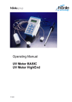
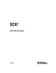
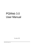
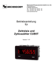
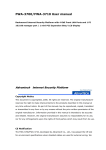
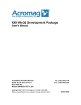
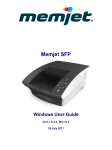
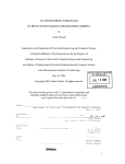
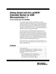
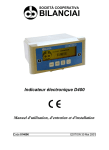
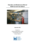
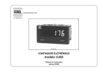
CUB5 Series Communication VI Library User Manual: Version 1.0 Copyright © 2009 Integrated Pro http://www.integratedpro.com TABLE OF CONTENTS CUB5 SERIES COMMUNICATION VI LIBRARY 1. Introduction 2. Installation 3. Communications Setup Finding the Communications Port Finding the Controller Address and Serial Baud Rate 4. Using Example VIs CUB5 Counter Example Query Device.vi CUB5 Timer Example Query Device.vi CUB5 Counter Example Panel and Log.vi CUB5 Timer Example Panel and Log.vi CUB5 Analog Example Panel and Log.vi 5. Creating Custom VIs A Basic VI Application Adding More Functionality Changing Configuration Values Timer Formats 6. Library Reference VIs for All Devices VIs for CUB5 Counter VIs for CUB5T Timer VIs for CUB5, CUB5I, CUB5RT, CUB5P Analog Meters 7. Optional Parameters Optional Timing Parameters Optional Scaling Value Notices Copyright © 2009 Integrated Pro. ALL RIGHTS RESERVED. http://www.integratedpro.com ‐ 3 ‐ 1. Introduction This VI library contains VIs (Virtual Instruments) and example code for implementing communication between LabVIEWTM from National Instruments and a Red Lion® Controls* CUB5 series panel meter via RS‐485 serial bus. The CUB5 series includes several different types of panel meters including the CUB5 counter, CUB5T timer, CUB5V DC voltage meter, CUB5I DC current meter, CUB5RT Temperature meter, and CUB5P Process Meter (4‐20mA). Communication between LabVIEW and CUB5 series panel meter, allows expanded capabilities such as the ability to log and trend the panel meter value or to remotely change the configuration values on the meter. A single instance of LabVIEW running on a PC can access multiple panel meters and other devices throughout an installation via the RS‐485 bus to provide a central view or coordinated control and data acquisition capability at very low cost. The CUB5 device requires an optional serial interface that is available from Red Lion Controls in order to communicate via serial. Although recommended for RS‐485 serial communication, these VIs can also be used with RS‐232 serial or USB serial communication if that type of interface is used. Because addressing is not supported by RS‐232 serial or USB serial communication, this applies only to a single CUB5 device that is directly connected to the PC. It is assumed in this document that the reader is familiar with how to program and use LabVIEW. Hardware and wiring are beyond the scope of this document. If you need help setting up the RS‐485 serial bus, please consult the user manual for the panel meter, your RS‐ 485 serial interface documentation or one of the numerous references on the internet. More information about LabVIEW is available at http://www.ni.com/labview and RS‐485 references are also available at http://www.integratedpro.com CAUTION!!!! The VI library can change the configuration, setpoint or other operating parameters of your device(s) and/or other devices connected to the RS‐485 bus, resulting in changes to device behavior and especially if the device is connected to a physical process (i.e. operational and controlling something!) Never experiment with an operational device – for development purposes it is recommended to only use an offline device, on an isolated RS‐485 serial bus until you have thoroughly verified functionality and safety in your application. *Integrated Pro is not affiliated with Red Lion® Controls. Copyright © 2009 Integrated Pro. ALL RIGHTS RESERVED. http://www.integratedpro.com ‐ 4 ‐ 2. Installation Install the VI library by running the installation program, setup.exe. Choose the installation directory, and review the Software License Agreement. The VI library installs under the most current version of LabVIEW. Be sure to review the Readme.txt file information at the end of the installation. Restart LabVIEW after installing so that the library VIs will show up on the Tools palette (right click the block diagram). You can find them on the CUB5 series palette under User Libraries. You can access help and example VIs under the LabVIEW Help menu. It is recommended that you Mass Compile the VI library to make sure that the VIs are compiled in your version of LabVIEW and that all of the VIs link to their necessary suVIs. Open the Mass Compile dialog from the Tools‐>Advanced‐>Mass Compile menu and navigate to the folder [LabVIEW]\user.lib\CUB5 Series (where [LabVIEW] represents the folder where LabVIEW is installed). Make sure you are inside CUB5 Series folder and choose “Current Folder”, then “Mass Compile”. Note that the message “Bad VI … VI Tree CUB5 series.vi” is expected (this VI is not intended to be operational, but only to present the subVIs in categories). Copyright © 2009 Integrated Pro. ALL RIGHTS RESERVED. http://www.integratedpro.com ‐ 5 ‐ 3. Communications Setup Before using the VI library, you need to know three things: 1. Which communications port your RS‐485 serial interface is using to communicate with the Controller. You can then use this information to set the VISA Resource which LabVIEW will use to communicate with the controller. 2. The address of the Controller on the RS‐485 serial bus. This will be a number between 1 and 255. 3. The serial baud rate. By default, this is set to 9600 baud. Other serial settings should be set to 8 bit data, No parity, and 1 Stop bit. Finding the Communications Port To find out this information consult the documentation for your RS‐485 serial interface. Most RS‐485 serial interfaces install under Windows as a standard serial port, such as COM5, COM6, etc. In Windows, you can view the installed serial ports under the device manager. MAC OS and Linux have similar utilities. Finding the Controller Address and Serial Baud Rate On the CUB5 series panel meters, the Controller address and serial settings are found using the Serial settings programming menu (press and hold the SEL button until the programming menus appear, press the RST button to enter programming mode and then use the SEL button to choose the Serial settings programming menu). Consult the CUB5 panel meter manual for further details. All devices on the RS‐485 serial bus must use the same serial baud rate, but have different addresses. LabVIEW acts as a serial Master device and the Controller acts as a Slave device. The VI library only supports RTU mode, not ASCII communications. Copyright © 2009 Integrated Pro. ALL RIGHTS RESERVED. http://www.integratedpro.com ‐ 6 ‐ 4. Using Example VIs Example VIs are included with the VI library including: CUB5 Counter Example Query Settings.vi CUB5 Timer Example Query Settings.vi CUB5 Counter Example Panel and Log.vi CUB5 Analog Example Panel and Log.vi CUB5 Timer Example Panel and log.vi These VIs are contained in the folder: [LabVIEW]\examples\CUB5 series, where [LabVIEW] represents the path to your LabVIEW installation. They demonstrate how to use the subVIs contained in the VI library to communicate with the panel meter and are meant to be starting points for verifying communication and for use in creating your own custom VIs. It is assumed that the CUB5 series device is properly wired and configured for communication. Example VIs can be accessed either under CUB5 Series library on the LabVIEW Help menu or from the Tools Palette (right‐click on the block diagram). On the Tools Palette, choose the CUB5 Series panel meter palette under User Libraries as shown in Figure 1. When you drop one of the example VIs on a block diagram, it will automatically open to show the front panel. CUB5 Counter Example Query Device.vi The purpose of this VI is to query the settings of the CUB5 counter at the address you provide and to report this in text form. The front panel of this example VI is shown in Figure 2. To run this example VI, follow the instructions on the front panel. The VI will execute a single time and the Status Information will report some status and configurable settings of the panel meter, for example: the current values for the Count and Rate, the Scale Factor and Count Load value (value loaded on reset). This information is also shown on the indicators on the right hand side of the front panel. Copyright © 2009 Integrated Pro. ALL RIGHTS RESERVED. http://www.integratedpro.com ‐ 7 ‐ Figure 1 ‐ CUB5 Series library VIs under User Libraries on the Tools Palette CUB5 Timer Example Query Device.vi The purpose of this VI is to query the settings of the CUB5 timer at the address you provide and to report this in text form. The front panel of this example VI is shown in Figure 3. To run this example VI, follow the instructions on the front panel. The VI will execute a single time and the Status Information will report some status and configurable settings of the panel meter, for example: the current values for the Timer and Cycles, Timer Start value, Timer Stop value, and Cycle Count Start value. This information is also shown on the indicators on the right hand side of the front panel. CUB5 Counter Example Panel and Log.vi The purpose of this VI is to simulate the front panel of the CUB 5 counter, showing the Count and Rate values. Trend values of Count and Rate are logged to a chart on the front panel at about every second. The front panel of this example VI is shown in Figure 4. Follow the instructions on the front panel. The VI executes in a loop, with an event structure controlling the update rate and responding to user input from the front panel controls. By default, the VI will only retrieve the values of Count and Rate. By turning the Write Enable switch ON, the VI can be used to set the Count using the Update Count numeric control. Copyright © 2009 Integrated Pro. ALL RIGHTS RESERVED. http://www.integratedpro.com ‐ 8 ‐ Figure 2 – CUB5 Counter Example Query Device VI front panel Figure 3 ‐ CUB5 Timer Example Query Device VI front panel Copyright © 2009 Integrated Pro. ALL RIGHTS RESERVED. http://www.integratedpro.com ‐ 9 ‐ CUB5 Timer Example Panel and Log.vi The purpose of this VI is to simulate the front panel of the CUB5 timer, showing the Time and Cycle Count values. Trend values of Time and Cycle Count are logged to a chart on the front panel at about every second. The front panel of this example VI is shown in Figure 5. Follow the instructions on the front panel. The VI executes in a loop, with an event structure controlling the update rate and responding to user input from the front panel controls. CUB5 Analog Example Panel and Log.vi The purpose of this VI is to simulate the front panel of the CUB5 Analog Meter (DC Voltage, DC Current, Temperature, or Process Meter), showing the Input value. Trend values of the Input are logged to a chart on the front panel at about every second. The front panel of this example VI is shown in Figure 6. Follow the instructions on the front panel. The VI executes in a loop, with an event structure controlling the update rate and responding to user input from the front panel controls. Figure 4 ‐ CUB5 Counter Example Panel and Log VI front panel Copyright © 2009 Integrated Pro. ALL RIGHTS RESERVED. http://www.integratedpro.com ‐ 10 ‐ Figure 5 ‐ CUB5 Timer Example Panel and Log VI front panel Figure 6 ‐ CUB5 Analog Meter Example Panel and Log VI front panel Copyright © 2009 Integrated Pro. ALL RIGHTS RESERVED. http://www.integratedpro.com 5. Creating Custom VIs After using the example VIs to verify communications between LabVIEW and the device, you can use the VI library to create your own custom VIs or modify the examples. Here is a simple example showing how to use a few of the library VIs to develop a custom VI. CAUTION!!!! The VI library can change the configuration, setpoint or other operating parameters of your device(s) and/or other devices connected to the RS‐485 bus, resulting in changes to device behavior and especially if the device is connected to a physical process (i.e. operational and controlling something!) Never experiment with an operational device – for development purposes it is recommended to only use an offline device, on an isolated RS‐485 serial bus until you have thoroughly verified functionality and safety in your application. A Basic VI Application Start with a blank VI and open the CUB5 Series VI pallettes by right‐clicking on the block diagram of the new VI, choosing User Libraries from the Tools Palette and opening the CUB5 series Controller palette as shown in Figure 1. Make it stay open “Pinning” the palette (click the push‐pin icon in the upper left hand corner) of the CUB5 series Controller palette. Drag the Initialize CUB5.vi and Close CUB5.vi onto the block diagram. Now open the Data sub‐ pallette. Depending upon which type of device you have: if your device is a CUB5 counter, then drag Read Count CUB5.vi onto the block diagram; or if your device is a CUB5T timer, then drag Read Timer CUB5T onto the block diagram; or if your device is a CUB5V, CUB5I, CUB5RT or CUB5P, then drag the Read Input CUB5 Analog.vi onto the block diagram. Arrange the VIs on the block diagram as shown in Figure 7 (CUB5 counter example shown). You can view the connector pane for each of the subVIs by turning on the LabVIEW context help (the ? button in the upper right of the block diagram window) and hovering with the mouse over each of the icons. Notice that there are required inputs on some of the subVIs, so connect these up to a control or a constant. The VISA resource name, Baud Rate and Controller Address controls can be easily created by right clicking on the appropriate VI inputs on the block diagram and choosing Create‐>Control, from the right‐mouse click menu. When correctly wired, the front panel and block diagram should look similar to Figure 7 and Figure 8. Set the VISA resource name, Baud rate, and Device Address. Save the VI and run it. The value shown on the front panel (in the example shown, Count) should now correspond to the value on the CUB5 series panel meter. Copyright © 2009 Integrated Pro. ALL RIGHTS RESERVED. http://www.integratedpro.com ‐ 12 ‐ Figure 7 – Basic Application VI front panel Figure 8 – Basic Application VI block diagram Copyright © 2009 Integrated Pro. ALL RIGHTS RESERVED. http://www.integratedpro.com ‐ 13 ‐ Adding More Functionality The basic pattern for the subVIs on the block diagram is always similar to that shown in the simple example, except that the Initialize CUB5.vi and Close CUB5.vi subVIs are only called at the beginning and end of the program and only once for any particular RS‐485 serial bus, even if there are multiple Controllers. To further illustrate things, let’s add a timed loop to read the values of the input to the CUB5 device. Using the Basic Application VI as a starting point (save it as a new VI if you would like), add a timed loop (found on the Timed Structures subpalette of the Structures palette) to control how often the values read from the device are updated. Leave the default timing values (1000ms update) and don’t forget to add a STOP button control. You can add other VIs from the Data sub‐palette of the CUB5 series library if you would like (for instance, Read Rate CUB5.vi in the example shown) Your front panel should look similar to Figure 10. Notice that the VISA resource and error wires are connected through all the subVIs from left to right and that each individual library VI in the middle of the program requires the Device Address input. If you have multiple controllers on your RS‐485 serial bus, you can call them individually by simply changing the controller address input on the given subVI. Running the VI should cause the values shown on the front panel to update approximately once per second to match the values on the front panel of the Device. Figure 9 ‐ Simple Example VI front panel Copyright © 2009 Integrated Pro. ALL RIGHTS RESERVED. http://www.integratedpro.com ‐ 14 ‐ Figure 10 ‐ Simple Example block diagram Changing Configuration Values If you want to add the ability to change a configuration value on the Device, this can be done by inserting a subVI and using the Set/Get property. For example, the block diagram of a simple VI to change the Cycle Count Start Value for a CUB5T Timer would look similar to Figure 11Figure 11, where the Set or Get Cycle Count Start Value CUB5.vi is used. The default value of the Set/Get property is to Get (read) the current configuration value. If it is desired to change the value, then the desired values must be wired to the appropriate input of the subVI and the Set/Get property must be changed to Set (write). Note that the subVI will always Get (read) the value of the property after setting it and return the current configuration value. Copyright © 2009 Integrated Pro. ALL RIGHTS RESERVED. http://www.integratedpro.com ‐ 15 ‐ Figure 11 ‐ Using Set/Get property to read or write configuration values Timer Formats The CUB5T Timer device can display time values in a number of formats on the front panel of the device. Internally on the device, all of these formats are converted to a 7 place, unsigned integer value and the decimal place (if any) shown on the front panel of the device is assumed according to the format chosen in the Device setup menu. This makes it necessary to use an assumed choice for the Timer Range input when displaying the time value as shown on the actual CUB5T device in LabVIEW. Additionally, the VI Library uses a typedef cluster, named Time Values, containing individual numeric controls for the values of Days, Hours, Minutes and Seconds, as an input and output of subVIs that read and write time values to and from the CUB5T Timer Device and the time values are converted to and from the device format as required. The Timer Range input and the Time Values cluster are shown on the front panel shown in Figure 12. Several VIs are provided for manipulating the time formats and values. These are illustrated in CUB5T Timer Example Panel and Log.vi and CUB5T Timer Example Query Device.vi example applications. Copyright © 2009 Integrated Pro. ALL RIGHTS RESERVED. http://www.integratedpro.com ‐ 16 ‐ Figure 12 ‐ Read Timer CUB5T.vi front panel showing Timer Range and time values controls Copyright © 2009 Integrated Pro. ALL RIGHTS RESERVED. http://www.integratedpro.com 6. Library Reference Each of the subVIs in the VI library is shown on the VI Tree.vi block diagram in Figure 13 (this VI is not executable). The VIs in the library and the VI Tree.vi can all be accessed by right‐clicking on the block diagram of a new VI, choosing User Libraries and opening the C Series Controller palette as shown before in Figure 1. As shown in Figure 13, the subVIs in the VI library are divided into different categories, approximately indicating their usage in communicating with the Device. The VIs in the Configuration and Action/Status categories use the Set/Get property to read or write configuration values. The VIs in the Data category are used to read or write data values, such as the value of the Input or the Count. Most of the subVIs in the VI library perform functions described in the user manual for the device. A listing of the functions of each of the subVIs in the library follows, categorized by the CUB5 series device to which they apply. These descriptions for each subVI are also contained in the VI documentation for each individual subVI. This can be easily viewed by turning on the LabVIEW context help (the ? button in the upper right of the block diagram window) and hovering with the mouse over each of the subVI icons, or by accessing the VI properties. Figure 13 ‐ VI Tree.vi block diagram showing library subVIs Copyright © 2009 Integrated Pro. ALL RIGHTS RESERVED. http://www.integratedpro.com ‐ 18 ‐ VIs for All Devices Block Print CUB5.vi Requests a block print string from the device. The content of the reply string will depend on the User Input Function Setup Parameters on the actual device (see CUB5 manual). An Optional Timing cluster input is included to vary the delay after the request until the response is read to allow the entire string to be transmitted. Depending on length of the reply string you may wish to adjust the Optional Read Delay value of this cluster. The default delay is 1 second. Error checking is used ‐ If error input is wired, this VI checks for previous errors and does not execute if error. Inputs VISA Resource (Port) Device Address (I32) Optional Timing Parameters (optional) error in (no error) Outputs VISA Resource OUT Block Print Reply error out Required. Device address on RS‐485 bus. Required. Use to adjust the read delay between sending the block print request and receiving the reply string. Pass‐thru String received from the device in response to the block print request. Connector Pane Close CUB5.vi Terminates the software connection to serial port. Call this VI to make sure the serial port is closed at the end of your application. Inputs VISA resource name (Port) error in (no error) Outputs Choose VISA resource corresponding to serial port you are using. Required. Copyright © 2009 Integrated Pro. ALL RIGHTS RESERVED. http://www.integratedpro.com ‐ 19 ‐ error out Connector Pane Initialize CUB5.vi Initializes Serial Communications on given port at chosen baud rate. Returns error if unsuccessful. Call this VI before calling other VIs, but generally, you need to call the Initialize VI only once at the beginning of an application. Uses the following serial port settings: 8bit data, No Parity, 1 Stop bit with Termination Character disabled, with port timeout of 10 seconds. Other settings are at default for the platform. Also stores global Optional Timing Parameters to be used in RS‐485 communications. These values specify values specific to RS‐485 (modbus) communications that are to be used throughout the program. Unless you have a good reason for doing so, it is not necessary to change these values: Max Retries (5): The number of times the program will retry automatically after receiving a serial communication error. Optional write delay (20ms): The modbus specification requires that the RS‐485 serial bus be quiet between transmitted messages. These delays are based on the baud rate. Often it is desirable to insert additional delay to account for noise, slow settling, slow device response or other factors. This optional delay is inserted before the required minimum delay before a message is written. Optional read delay (20ms): (see above) This optional delay is inserted before the required minimum delay before a reply is read. Device read timeout (200ms): Specifies how long to wait for a reply from the device before retrying. This is a programmatic delay and not the same thing as the VISA serial port timeout. Termination Delay Character (* 50ms): CUB5 devices determine how long to wait after receiving a command before replying based on this character, which is part of the command string written to the device. * = 50ms (recommended for RS‐485) and $ = 2ms Copyright © 2009 Integrated Pro. ALL RIGHTS RESERVED. http://www.integratedpro.com ‐ 20 ‐ (recommended for RS‐232 or USB only, both of which can only be used with a single device on a direct connection). Inputs VISA resource name (Port) Baud Rate Optional Timing Parameters (typedef) Error In (no error) Outputs VISA resource name out error out Choose VISA resource corresponding to serial port you are using. Required. Select the baud rate corresponding to the settings on the Process Controller. Required. Pass‐thru Connector Pane VIs for CUB5 Counter Read Count CUB5.vi Reads count from Counter (specify Counter A or Counter B with input). Error checking is used ‐ If error input is wired, this VI checks for previous errors and does not execute if error. Inputs VISA Resource (Port) Required. Device Address (I32) Device address on RS‐485 bus. Required. Counter (enum) Set to choose Counter A or Counter B. Scaling value (double) Optional input to adjust scaling of Counter value output (default is no scaling). This value can be used to set the decimal place if desired. error in (no error) Outputs VISA Resource OUT Pass‐thru Count (double) Count read from counter error out Copyright © 2009 Integrated Pro. ALL RIGHTS RESERVED. http://www.integratedpro.com ‐ 21 ‐ Connector Pane Read Rate CUB5.vi Reads Rate from Counter. Error checking is used ‐ If error input is wired, this VI checks for previous errors and does not execute if error. Inputs VISA Resource (Port) Required. Device Address (I32) Device address on RS‐485 bus. Required. Scaling value (double) Optional input to adjust scaling of Counter value output (default is no scaling). This value can be used to set the decimal place if desired. error in (no error) Outputs VISA Resource OUT Pass‐thru Rate (double) Rate Value read from counter error out Connector Pane Reset Counter CUB5.vi Resets count from Counter (specify Counter A or Counter B with input). The value of the counter after reset will depend on the Input Setup Parameters on the actual device (see CUB5 manual). Read the count using Read Counter.vi after calling this VI to verify reset. Error checking is used ‐ If error input is wired, this VI checks for previous errors and does not execute if error. Inputs Copyright © 2009 Integrated Pro. ALL RIGHTS RESERVED. http://www.integratedpro.com ‐ 22 ‐ VISA Resource (Port) Device Address (I32) Counter (enum) error in (no error) Outputs VISA Resource OUT error out Required. Device address on RS‐485 bus. Required. Set to choose Counter A or Counter B. Pass‐thru Connector Pane Reset Counter Setpoint CUB5.vi Resets the Counter Setpoint Output (specify Setpoint 1 or Setpoint 2 with input). The action of the setpoint under reset conditions depends on counter setup (see Manual). Error checking is used ‐ If error input is wired, this VI checks for previous errors and does not execute if error. Inputs VISA Resource (Port) Required. Device Address (I32) Device address on RS‐485 bus. Required. Setpoint (enum) Set to choose Setpoint 1 or Setpoint 2. error in (no error) Outputs VISA Resource OUT Pass‐thru error out Connector Pane Set or Get Scale Factor CUB5.vi Use this VI to get or set the value of the scale factor (specify Counter A or Counter B with input). The value of the scale factor must be within the limit of the counter. This is NOT checked by this VI. The current setpoint is always returned by this VI. Copyright © 2009 Integrated Pro. ALL RIGHTS RESERVED. http://www.integratedpro.com ‐ 23 ‐ The desired scale factor is a six digit positive number with assumed 4 decimal places and the returned scale factor value is shifted 4 decimal places to become a six digit positive number after being read. For example: a desired scale factor of 1.000 must be entered as an I32 value of 10000 and a returned scale factor I32 value of 200 corresponds to a count scale factor of 0.0200 on the device (see Counter documentation). Error checking is used ‐ If error input is wired, this VI checks for previous errors and does not execute if error. Inputs VISA Resource (Port) Required. Device Address (I32) Device address on RS‐485 bus. Required. Operation (enum) Use to choose whether to Set or Get value Counter (enum) Set to choose Counter A or Counter B Desired Scale Factor (I32) Desired Scale Factor error in (no error) Outputs VISA Resource OUT Pass‐thru Scale Factor (I32) current scale factor value (after Set operation, if applicable) error out Connector Pane Set or Get Timer Setpoint ON Value CUB5T.vi Use this VI to get or set the value of the Timer Setpoint ON Value (SPT) on the timer. The input value is a 7 digit integer and is interpreted by the device according to the Timer range as set on the device. Signs are disregarded (all numbers are treated as positive values). The range of the 7 digit integer is checked to be between 9999999 and 0 and an error is returned if out of range. Note that for mixed unit ranges including seconds or minutes where the maximum value for a unit is 59, this check is not sufficient. For example, the value 9999999 will be clipped to 9995959 by the device if the timer range on the device is HHHMMSS. Copyright © 2009 Integrated Pro. ALL RIGHTS RESERVED. http://www.integratedpro.com ‐ 24 ‐ Use Format Timer Value.vi to format the Timer Setpoint ON Value number according to a specific timer range (which should be chosen to correspond to the timer range on the device) and check individual unit values. The current Timer Setpoint ON Value is always returned by this VI. Requires input "Timer Range" which corresponds to one of the 18 possible timer ranges (for example MMM.SS.SS) on the front panel of the device. This needs to be set according to the actual device setting so that the timer value is interpreted correctly. Error checking is used ‐ If error input is wired, this VI checks for previous errors and does not execute if error. Inputs VISA Resource (Port) Required. Device Address (I32) Device address on RS‐485 bus. Required. Operation (enum) Use to choose whether to Set or Get value Timer Setpoint ON (enum) Set to one of 18 timer modes as set on device (for example MMM.SS.SS) Desired Timer Setpoint ON Value (I32) Desired Timer Setpoint ON Value error in (no error) Outputs VISA Resource OUT Pass‐thru Timer Setpoint ON Value (I32) current value of Setpoint ON value (after Set operation, if applicable) error out Connector Pane Set or Get Count Load Value CUB5.vi Use this VI to get or set the value of the Count Load Value for Counter A. The value of the Count Load Value must be within the limit of the counter. This is NOT checked by this VI. The desired Count Load Value is divided by scaling value (default = 1.0) to correspond to the counter scaling factor and converted to I16 before being written. The current count load value is always returned by this VI. Copyright © 2009 Integrated Pro. ALL RIGHTS RESERVED. http://www.integratedpro.com ‐ 25 ‐ Error checking is used ‐ If error input is wired, this VI checks for previous errors and does not execute if error. Inputs VISA Resource (Port) Required. Device Address (I32) Device address on RS‐485 bus. Required. Operation (enum) Use to choose whether to Set or Get value Desired Count Load Value (double) Desired Setpoint value Scaling value (double) Optional input to adjust scaling of Setpoint value output (default is no scaling). error in (no error) Outputs VISA Resource OUT Pass‐thru Count Load Value (double) current value of count load value (after Set operation, if applicable) error out Connector Pane Set or Get Setpoint CUB5.vi Use this VI to get or set the value of the setpoint (specify Setpoint 1 or Setpoint 2 with input). The value of the setpoint must be within the limit of the counter. This is NOT checked by this VI. The desired setpoint is divided by scaling value (default = 1.0) to correspond to the counter scaling factor and converted to I16 before being written. The current setpoint is always returned by this VI. Error checking is used ‐ If error input is wired, this VI checks for previous errors and does not execute if error. Inputs VISA Resource (Port) Required. Device Address (I32) Device address on RS‐485 bus. Required. Operation (enum) Use to choose whether to Set or Get value Setpoint (enum) Set to choose Setpoint 1 or Setpoint 2. Desired Setpoint (double) Desired Setpoint value Scaling value (double) Optional input to adjust scaling of Setpoint value output (default is no scaling). Copyright © 2009 Integrated Pro. ALL RIGHTS RESERVED. http://www.integratedpro.com ‐ 26 ‐ error in (no error) Outputs VISA Resource OUT Setpoint Value (double) error out Pass‐thru current value of setpoint (after Set operation, if applicable) Connector Pane Write Count CUB5.vi Writes desired count value to Counter (specify Counter A or Counter B with input). The desired count value is divided by scaling value (default = 1.0) to correspond to the counter scaling factor and converted to I16 before being written. Error checking is used ‐ If error input is wired, this VI checks for previous errors and does not execute if error. Inputs VISA Resource (Port) Device Address (I32) Counter (enum) Scaling value (double) Desired Count (double) error in (no error) Outputs VISA Resource OUT error out Required. Device address on RS‐485 bus. Required. Set to choose Counter A or Counter B. Optional input to adjust scaling of Counter value output (default is no scaling). Count written to panel meter Pass‐thru Connector Pane Copyright © 2009 Integrated Pro. ALL RIGHTS RESERVED. http://www.integratedpro.com ‐ 27 ‐ VIs for CUB5T Timer Format Timer Value CUB5T.vi Formats Time Value for Write Timer.vi, Set or Get Timer Start Value.vi, Set or Get Timer Stop Value.vi from individual Day,Hour,Minute,Second unit values. This VI checks ranges on individual unit values (for instance max 59 seconds, max 999 hours, etc). Returns error if out of range. Wire error output from this VI to error input of Write Timer.vi, Set or Get Timer Start Value.vi, Set or Get Timer Stop Value.vii, if used to keep Write Timer CUB5.vi from executing if the inputs are out of range. Requires input "Timer Range" which corresponds to one of the 18 possible timer ranges (for example MMM.SS.SS) on the front panel of the device. This needs to be set according to the actual device setting so that the timer value is interpreted correctly. Inputs VISA Resource (Port) Pass‐thru only (so VI can be wired in front of other Write VIs) Set to one of 18 timer modes as set on device (for example MMM.SS.SS) time units values to be format as timer value Pass‐thru Use as input to Write Timer CUB5.vi Timer Range (enum, required) Time Values (cluster, typedef) error in (no error) Outputs VISA Resource OUT Timer Value (I32) error out Connector Pane Copyright © 2009 Integrated Pro. ALL RIGHTS RESERVED. http://www.integratedpro.com ‐ 28 ‐ Read Cycles CUB5T.vi Reads current cycle count of timer (CUB5T). Error checking is used ‐ If error input is wired, this VI checks for previous errors and does not execute if error. Inputs VISA Resource (Port) Device Address (I32) error in (no error) Outputs VISA Resource OUT Cycle Count (I32) error out Required. Device address on RS‐485 bus. Required. Pass‐thru cycle count on timer Connector Pane Read Timer CUB5T.vi Reads current value of timer (CUB5T). Error checking is used ‐ If error input is wired, this VI checks for previous errors and does not execute if error. Requires input "Timer Range" which corresponds to one of the 18 possible timer ranges (for example MMM.SS.SS) on the front panel of the device. This needs to be set according to the actual device setting so that the timer value is interpreted correctly. Inputs VISA Resource (Port) Device Address (I32) Timer Range (enum) error in (no error) Outputs VISA Resource OUT Timer Value (typedef cluster, double) Required. Device address on RS‐485 bus. Required. Set to one of 18 timer modes as set on device (for example MMM.SS.SS) Pass‐thru Cluster output of Days, Hours, Minutes, Seconds. Content will depend on the value read from the device as interpreted by the Timer Range input. Wire only valid values Copyright © 2009 Integrated Pro. ALL RIGHTS RESERVED. http://www.integratedpro.com ‐ 29 ‐ string out (string) error out per timer range input used. timer string read from the device (useful for debugging) Connector Pane Reset Cycles CUB5T.vi Resets cycle count from timer (CUB5T). The value of the cycle count after reset will depend on the counter start parameter on the device (see CUB5 manual). Read the count using Read Cycles.vi after calling this VI to verify reset. Error checking is used ‐ If error input is wired, this VI checks for previous errors and does not execute if error. Inputs VISA Resource (Port) Device Address (I32) error in (no error) Outputs VISA Resource OUT error out Required. Device address on RS‐485 bus. Required. Pass‐thru Connector Pane Copyright © 2009 Integrated Pro. ALL RIGHTS RESERVED. http://www.integratedpro.com ‐ 30 ‐ Reset Timer CUB5T.vi Resets timer (CUB5T). The value of the timer after reset will depend on the timer start parameter on the device (see CUB5 manual). Read the count using Read Timer.vi after calling this VI to verify reset. Error checking is used ‐ If error input is wired, this VI checks for previous errors and does not execute if error. Inputs VISA Resource (Port) Device Address (I32) error in (no error) Outputs VISA Resource OUT error out Required. Device address on RS‐485 bus. Required. Pass‐thru Connector Pane Reset Timer Setpoint CUB5T.vi Resets timer setpoint (CUB5T) per Setpoint Assignment on the Device (see manual). Error checking is used ‐ If error input is wired, this VI checks for previous errors and does not execute if error. Inputs VISA Resource (Port) Device Address (I32) error in (no error) Outputs VISA Resource OUT error out Required. Device address on RS‐485 bus. Required. Pass‐thru Connector Pane Copyright © 2009 Integrated Pro. ALL RIGHTS RESERVED. http://www.integratedpro.com ‐ 31 ‐ Set or Get Cycle Count Start Value CUB5T.vi Use this VI to get or set the value of the Cycle Count Start (CST) Value on the timer. The value of the Cycle Count Start Value must be within the 6 digit limit of the counter or the value is not written and an error is returned. The current Cycle Count Start Value is always returned by this VI. Error checking is used ‐ If error input is wired, this VI checks for previous errors and does not execute if error. Inputs VISA Resource (Port) Device Address (I32) Operation (enum) Desired Cycle Count Start Value (I32) error in (no error) Outputs VISA Resource OUT Cycle Count Start Value (I32) error out Required. Device address on RS‐485 bus. Required. Use to choose whether to Set or Get value Desired Cycle Count Start Value Pass‐thru current value of cycle count start value (after Set operation, if applicable) Connector Pane Set or Get Setpoint Time‐out Value CUB5T.vi Use this VI to get or set the value of the Timer Setpoint Time‐out Start (STO) Value on the timer. When writing, the input is assumed to be in the format MM.ss.ss where the decimal points are Copyright © 2009 Integrated Pro. ALL RIGHTS RESERVED. http://www.integratedpro.com ‐ 32 ‐ ignored (see device manual). The value of the Timer Setpoint Time‐out Value must be within the 6 digit limit of the counter or the value is not written and an error is returned. The current Timer Setpoint Time‐out Value is always returned by this VI. Error checking is used ‐ If error input is wired, this VI checks for previous errors and does not execute if error. Inputs VISA Resource (Port) Device Address (I32) Operation (enum) Desired Setpoint Time‐out Value (I32) error in (no error) Outputs VISA Resource OUT STO string (string) Timer Setpoint Time‐out Value (enum, typedef) error out Required. Device address on RS‐485 bus. Required. Use to choose whether to Set or Get value Desired Setpoint Time‐out value in MM.ss.ss format (decimals ignored) Pass‐thru actual string returned from the timer current value of timer setpoint time‐out value (after Set operation, if applicable) Connector Pane Set or Get Timer Setpoint OFF Value CUB5T.vi Use this VI to get or set the value of the Timer Setpoint OFF Value (SOF) on the timer. The input value is a 7 digit integer and is interpreted by the device according to the Timer range as set on the device. Signs are disregarded (all numbers are treated as positive values). The range of the 7 digit integer is checked to be between 9999999 and 0 and an error is returned if out of range. Note that for mixed unit ranges including seconds or minutes where the maximum value for a unit is 59, this check is not sufficient. For example, the value 9999999 will be clipped to 9995959 by the device if the timer range on the device is HHHMMSS. Copyright © 2009 Integrated Pro. ALL RIGHTS RESERVED. http://www.integratedpro.com ‐ 33 ‐ Use Format Timer Value.vi to format the Timer Setpoint OFF value number according to a specific timer range (which should be chosen to correspond to the timer range on the device) and check individual unit values. The current Timer Setpoint OFF Value is always returned by this VI. Requires input "Timer Range" which corresponds to one of the 18 possible timer ranges (for example MMM.SS.SS) on the front panel of the device. This needs to be set according to the actual device setting so that the timer value is interpreted correctly. Error checking is used ‐ If error input is wired, this VI checks for previous errors and does not execute if error. Inputs VISA Resource (Port) Device Address (I32) Operation (enum) Timer Range (enum) Desired Timer Setpoint OFF Value (I32) error in (no error) Outputs VISA Resource OUT Timer Setpoint OFF Value (I32) error out Required. Device address on RS‐485 bus. Required. Use to choose whether to Set or Get value Set to one of 18 timer modes as set on device (for example MMM.SS.SS) Desired Timer Setpoint OFF Value Pass‐thru current value of timer setpoint OFF value (after Set operation, if applicable) Connector Pane Set or Get Timer Start Value CUB5T.vi Use this VI to get or set the value of the Timer Start Value (TST) on the timer. The input value is a 7 digit integer and is interpreted by the device according to the Timer range as set on the device. Signs are disregarded (all numbers are treated as positive values). The range of the 7 digit integer is checked to be between 9999999 and 0 and an error is returned if Copyright © 2009 Integrated Pro. ALL RIGHTS RESERVED. http://www.integratedpro.com ‐ 34 ‐ out of range. Note that for mixed unit ranges including seconds or minutes where the maximum value for a unit is 59, this check is not sufficient. For example, the value 9999999 will be clipped to 9995959 by the device if the timer range on the device is HHHMMSS. Use Format Timer Value.vi to format the Timer Start Value number according to a specific timer range (which should be chosen to correspond to the timer range on the device) and check individual unit values. The current Timer Start Value is always returned by this VI. Requires input "Timer Range" which corresponds to one of the 18 possible timer ranges (for example MMM.SS.SS) on the front panel of the device. This needs to be set according to the actual device setting so that the timer value is interpreted correctly. Error checking is used ‐ If error input is wired, this VI checks for previous errors and does not execute if error. Inputs VISA Resource (Port) Device Address (I32) Operation (enum) Timer Range (enum) Desired Timer Start Value (I32) error in (no error) Outputs VISA Resource OUT Timer Start Value (I32) error out Required. Device address on RS‐485 bus. Required. Use to choose whether to Set or Get value Set to one of 18 timer modes as set on device (for example MMM.SS.SS) Desired Timer Start Value Pass‐thru current value of timer start value (after Set operation, if applicable) Connector Pane Copyright © 2009 Integrated Pro. ALL RIGHTS RESERVED. http://www.integratedpro.com ‐ 35 ‐ Set or Get Timer Stop Value CUB5T.vi Use this VI to get or set the value of the Timer Stop Value (TSP) on the timer. The input value is a 7 digit integer and is interpreted by the device according to the Timer range as set on the device. Signs are disregarded (all numbers are treated as positive values). The range of the 7 digit integer is checked to be between 9999999 and 0 and an error is returned if out of range. Note that for mixed unit ranges including seconds or minutes where the maximum value for a unit is 59, this check is not sufficient. For example, the value 9999999 will be clipped to 9995959 by the device if the timer range on the device is HHHMMSS. Use Format Timer Value.vi to format the Timer Stop value number according to a specific timer range (which should be chosen to correspond to the timer range on the device) and check individual unit values. The current Timer Stop Value is always returned by this VI. Requires input "Timer Range" which corresponds to one of the 18 possible timer ranges (for example MMM.SS.SS) on the front panel of the device. This needs to be set according to the actual device setting so that the timer value is interpreted correctly. Error checking is used ‐ If error input is wired, this VI checks for previous errors and does not execute if error. Inputs VISA Resource (Port) Device Address (I32) Operation (enum) Timer Range (enum) Desired Timer Stop Value (I32) error in (no error) Outputs VISA Resource OUT Timer Stop Value (I32) error out Required. Device address on RS‐485 bus. Required. Use to choose whether to Set or Get value Set to one of 18 timer modes as set on device (for example MMM.SS.SS) Desired Timer Stop Value Pass‐thru current value of timer stop value (after Set operation, if applicable) Connector Pane Copyright © 2009 Integrated Pro. ALL RIGHTS RESERVED. http://www.integratedpro.com ‐ 36 ‐ Time Values to String CUB5T.vi Formats Timer Values from individual Day,Hour,Minute,Second unit values into a string value that matches the display format on the device. This VI checks ranges on individual unit values (for instance max 59 seconds, max 999 hours, etc). Returns error if out of range. Requires input "Timer Range" which corresponds to one of the 18 possible timer ranges (for example MMM.SS.SS) on the front panel of the device. This needs to be set according to the actual device setting so that the timer value is interpreted correctly. Inputs VISA Resource (Port) Pass‐thru only (so VI can be wired in front of other Write VIs) Set to one of 18 timer modes as set on device (for example MMM.SS.SS) Individual values for days, hours, minutes, seconds Pass‐thru formatted time values display string Timer Range (enum, required) Time Values (cluster, typedef) error in (no error) Outputs VISA Resource OUT Timer String (string) error out Connector Pane Write Cycles CUB5T.vi Writes desired cycle count value to Timer (CUB5T). Error checking is used ‐ If error input is wired, this VI checks for previous errors and does not execute if error. Copyright © 2009 Integrated Pro. ALL RIGHTS RESERVED. http://www.integratedpro.com ‐ 37 ‐ Inputs VISA Resource (Port) Device Address (I32) Desired Cycle Count (I32) error in (no error) Outputs VISA Resource OUT error out Required. Device address on RS‐485 bus. Required. Cycle Count written to timer Pass‐thru Connector Pane Write Timer CUB5T.vi Writes desired cycle count value to Timer (CUB5T). Error checking is used ‐ If error input is wired, this VI checks for previous errors and does not execute if error. The input value is a 7 digit integer and is interpreted by the device according to the Timer range as set on the device. Signs are disregarded (all numbers are treated as positive values). The range of the 7 digit integer is checked to be between 9999999 and 0 and an error is returned if out of range. Note that for mixed unit ranges including seconds or minutes where the maximum value for a unit is 59, this check is not sufficient. For example, the value 9999999 will be clipped to 9995959 by the device if the timer range on the device is HHHMMSS. Use Format Timer Value.vi to format the Timer Write number according to a specific timer range (which should be chosen to correspond to the timer range on the device) and check individual unit values. Inputs VISA Resource (Port) Device Address (I32) Desired Cycle Count (I32) error in (no error) Outputs VISA Resource OUT error out Required. Device address on RS‐485 bus. Required. Cycle Count written to timer Pass‐thru Copyright © 2009 Integrated Pro. ALL RIGHTS RESERVED. http://www.integratedpro.com ‐ 38 ‐ Connector Pane VIs for CUB5, CUB5I, CUB5RT, CUB5P Analog Meters Set or Get Setpoint CUB5 Analog.vi Use this VI to get or set the value of the setpoint on analog models of panel meter (specify Setpoint 1 or Setpoint 2 with input). The value of the setpoint must be within the limit of the counter. This is NOT checked by this VI. The desired setpoint is divided by scaling value (default = 1.0) to correspond to the meter scaling factor and converted to I16 before being written. The current setpoint is always returned by this VI. Error checking is used ‐ If error input is wired, this VI checks for previous errors and does not execute if error. Inputs VISA Resource (Port) Device Address (I32) Operation (enum) Setpoint (enum) Desired Setpoint (double) Scaling value (double) error in (no error) Outputs VISA Resource OUT Setpoint Value (double) error out Required. Device address on RS‐485 bus. Required. Use to choose whether to Set or Get value Set to choose Setpoint 1 or Setpoint 2. Desired Setpoint value Optional input to adjust scaling of Setpoint value output (default is no scaling). Pass‐thru current value of setpoint (after Set operation, if applicable) Connector Pane Copyright © 2009 Integrated Pro. ALL RIGHTS RESERVED. http://www.integratedpro.com ‐ 39 ‐ Read Input CUB5 analog.vi Reads current value of the input on analog models (CUB5V,CUB5I,CUB5P,CUB5TC,CUB5RT). Error checking is used ‐ If error input is wired, this VI checks for previous errors and does not execute if error. Inputs VISA Resource (Port) Device Address (I32) Scaling value (double) Scaling value (double) error in (no error) Outputs VISA Resource OUT Input Value (double) error out Required. Device address on RS‐485 bus. Required. Optional input to adjust scaling of Counter value output (default is no scaling). Optional input to adjust scaling of Counter value output (default is no scaling). This value can be used to set the decimal place if desired. Pass‐thru Input value on panel meter Connector Pane Read MaxMin CUB5 analog.vi Reads current MAX or MIN value of the input on analog models (CUB5V,CUB5I,CUB5P,CUB5TC,CUB5RT). This feature must be enabled on the meter (see Copyright © 2009 Integrated Pro. ALL RIGHTS RESERVED. http://www.integratedpro.com ‐ 40 ‐ manual). Error checking is used ‐ If error input is wired, this VI checks for previous errors and does not execute if error. Inputs VISA Resource (Port) Device Address (I32) MAX/MIN (enum, Maximum) Scaling value (double) error in (no error) Outputs VISA Resource OUT Max/Min Value (double) error out Required. Device address on RS‐485 bus. Required. Specifies whether to read Max or Min value on meter Optional input to adjust scaling of Counter value output (default is no scaling). Pass‐thru Max/Min value on meter (if enabled) Connector Pane Reset MaxMin CUB5 analog.vi Resets the Maximum or Minimum value on analog models of panel meter (specify Setpoint 1 or Setpoint 2 with input). Max/Min must be enabled on the meter and the action of the setpoint under reset conditions depends on panel meter setup (see Manual). Error checking is used ‐ If error input is wired, this VI checks for previous errors and does not execute if error. Inputs VISA Resource (Port) Device Address (I32) Max/Min (enum) error in (no error) Outputs VISA Resource OUT error out Required. Device address on RS‐485 bus. Required. Set to choose to reset MAX or MIN. Pass‐thru Copyright © 2009 Integrated Pro. ALL RIGHTS RESERVED. http://www.integratedpro.com ‐ 41 ‐ Connector Pane Reset Setpoint CUB5 analog.vi Resets the Setpoint Output on analog models of panel meter (specify Setpoint 1 or Setpoint 2 with input). The action of the setpoint under reset conditions depends on panel meter setup (see Manual). Error checking is used ‐ If error input is wired, this VI checks for previous errors and does not execute if error. Inputs VISA Resource (Port) Device Address (I32) Setpoint (enum) error in (no error) Outputs VISA Resource OUT error out Required. Device address on RS‐485 bus. Required. Set to choose Setpoint 1 or Setpoint 2. Pass‐thru Connector Pane Copyright © 2009 Integrated Pro. ALL RIGHTS RESERVED. http://www.integratedpro.com ‐ 42 ‐ 7. Optional Parameters Optional Timing Parameters Initialize CUB5.vi is used to open communications between LabVIEW and the RS‐485 bus. It also sets global values for the Optional Timing Parameters to be used in RS‐485 communications. These are values specific to RS‐485 communications that are used throughout the program. They can be modified through an input cluster on the Initialize CUB5.vi, but unless dictated by such factors as electrical interference on the RS‐485 bus, for instance, it is generally not necessary, nor is it recommended, to change these values: Max Retries (5): The number of times the program will retry automatically after receiving a serial communication error. Optional write delay (20ms): The specification requires that the RS‐485 serial bus be quiet between transmitted messages. These delays are based on the baud rate. It may be desirable to insert additional delay to account for noise, slow settling, slow device response or other factors. This optional delay is inserted before the required minimum delay, before a message is written. Optional read delay (20ms): (see Optional write delay, above) This optional delay is inserted before the required minimum delay, before a reply is read. Device read timeout (200ms): Specifies how long to wait for a reply from the device before retrying. This delay is a programmatic delay and not the same thing as the VISA serial port timeout, which will return an error in the case of hardware or other failure, and cause the subVI not to retry, but rather to return the error. Termination Delay Character (* 50ms): CUB5 devices determine how long to wait after receiving a command before replying based on this character, which is part of the command string written to the device. * = 50ms (recommended for RS‐485) and $ = 2ms (recommended for RS‐232 or USB only, both of which can only be used with a single device on a direct connection). Optional Scaling Value Some of the SubVIs that read or write the input value of the Device, or that adjust configuration parameters relating to the input value of the Device (such as Read Count CUB5.vi) have optional scale factor inputs. The default scaling value is 1.0 Unless you have a good reason for doing so, it is not recommended to change these values; however, if you do, you should make sure that all VIs having this input terminal receive the same value scale factor. Copyright © 2009 Integrated Pro. ALL RIGHTS RESERVED. http://www.integratedpro.com Notices All trademarks are property of their respective owners. Usage in this document of trademarks not owned by Integrated Pro is only to facilitate understanding on the part of the reader and no ownership or association is implied. Information furnished by Integrated Pro is believed to be accurate & reliable. No responsibility is assumed, however, by Integrated Pro for its use, whether correct or incorrect; nor can Integrated Pro be held liable for consequences or any infringements of patents or other rights of third parties which may result from its use. Information in this document is current as of date of writing and is subject to change. Copyright © 2009 Integrated Pro. ALL RIGHTS RESERVED. http://www.integratedpro.com