1
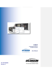
FWA-3700/FWA-3710 User manual
Rackmount Internet Security Platform with 4 GbE Front LAN Ports and 1 FE
10/100 manager port / 1 mini PCI Expansion Slots/ LCD Display
Advantech Internet Security Platform
Copyright Notice
This document is copyrighted, 2006. All rights are reserved. The original manufacturer
reserves the right to make improvements to the products described in this manual at
any time without notice. No part of this manual may be reproduced, copied, translated
or transmitted in any form or by any means without the prior written permission of the
original manufacturer. Information provided in this manual is intended to be accurate
and reliable. However, the original manufacturer assumes no responsibility for its use,
nor for any infringements upon the rights of third parties which may result from its use.
CE Notification
The FWA-3700/FWA-3710, developed by Advantech Co., Ltd., has passed the CE test
for environment specifications when shielded cables are used for external wiring. We
recommend the use of shielded cables.
1st Edition Printed in Taiwan March 2006
Product warranty
Advantech warrants to you, the original purchaser, that each of its products will be free
from defects in materials and workmanship for two year from the date of purchase.
This warranty does not apply to any products which have been repaired or altered by
persons other than repair personnel authorized by Advantech, or which have been
subject to misuse, abuse, accident or improper installation. Advantech assumes no
liability under the terms of this warranty as a consequence of such events.
Because of Advantech’s high quality-control standards and rigorous testing, most of our
customers never need to use our repair service. If an Advantech product is defective, it
will be repaired or replaced at no charge during the warranty period. For
out-of-warranty repairs, you will be billed according to the cost of replacement
materials, service time and freight. Please consult your dealer for more details. If you
think you have a defective product, follow these steps:
1
Collect all the information about the problem encountered. For example, CPU
speed, Advantech products used, other hardware and software used, etc. Note anything
abnormal and list any on-screen messages you get when the problem occurs.
2
Call your dealer and describe the problem. Please have your manual, product,
and any helpful information readily available.
3
If your product is diagnosed as defective, obtain an RMA (return merchandise
authorization) number from your dealer. This allows us to process your return more
quickly.
4
Carefully pack the defective product, a fully-completed Repair and Replacement
Order Card and a photocopy proof of purchase date (such as your sales receipt) in a
shippable container. A product returned without proof of the purchase date is not
eligible for warranty service.
5
Write the RMA number visibly on the outside of the package and ship it prepaid
to your dealer.
Packing List
Before installation, ensure that the following materials have been received:
One FWA-3700/FWA-3710 Internet Security Platform
One box of accessories
One warranty certificate
One CD-ROM for user manual (PDF file) If any of these items are missing or
damaged, contact your distributor or sales representative immediately.
ٛ
ٛ
ٛ
ٛ
Technical Support and Sales Assistance
If you have any technical questions about the FWA-3700 or any other Advantech
products, please visit our support website at:
http://www.advantech.com.tw/support
ٛ
http://www.advantech.com.
ٛ
For more information about Advantech's products and sales information, please visit:
Contents
1. General Information....................................... 1
1.1 Introduction......................................................................... 2
1.2 Features................................................................................. 2
1.3 Specifications................................................................... 2
1.4 Dimensions....................................................................4
1.5 Model List....................................................................5
2
System Setup............................................... 6
2.1 Removing the cover............................................................................. 7
2.2 Installing Central Processing Unit (CPU)...................................... 8
2.3 Installing Memory Module............................................................9
2.4 Installing Hard Drive........................................................................10
2.5 Installing Compact Flash...................................................11
2.6 Setting LAN Bypass function.........................................................12
Appendix A...................................................15
A.1 NAME-3700 Mother Board...............................................16
Figures
Figure 1-1: FWA-37x0 dimensions................................................................... 4Figure 1-2:
Outlook of FWA-37x0......................................................................... 4 Figure 2-1: Front
view
of
FWA-37x0..........................................................
cover.............................................................
7Figure
7Figure
2-3:
2-2:
Top
Removing
view
the
of
FWA-37x0.......................................................... 8Figure 2-4: Installing Central Processing
Unit
steps.....................................
steps..................................................
steps.............................................
steps....................................
9Figure
2-5:
Installing
10Figure
2-6:
Installing
11Figure
12Figure
2-8:
2-7:
The
Installing
illustration
Memory
Hard
Disk
Compact
of
LAN
Module
Drive
Flash
Bypass
function.................... 12Figure 2-9: LAN Bypass function jumps.......................................
13Figure 2-10: Setting LAN Bypass function from BIOS...................... 14
1
General Information
1.1 Introduction
Conceived as a powerful but low power consumption rack-mount Internet security
platform, the FWA-3700/FWA-3710 was specifically designed for mainstream IDS/IPS,
Anti-virus, VPN gateway and Unified Threat Management (UTM) applications. Using
the latest Intel Pentium M processor combined with the Mobile Intel 915GM Express
chipset and Intel ICH6M I/O Controller Hub, the FWA-3700 provides unprecedented
performance, connectivity and throughput without compromising on system thermal
design. It supports up to 2 GB of DDR2 system memory at 400 or 533MHz on
dual-channel SODIMM banks. By leveraging PCI-Express technology, the FWA-3700
maximizes I/O throughput by taking full advantage of the ICH6-M’s PCI Express (PCIe)
capability. Four PCIe lanes connect directly to the Marvell 8053 Ethernet controllers to
provide bi-directional 2 Gb/s peak bandwidth for Gigabit Ethernet support at wire
speed. The system supports one optional 3.5” IDE or SATA HDD, and Compact Flash
for OS and Internet security applications. The front panel has a 9-pin RS-232 serial
port and one 10/100 managed LAN port, with LCD Module for local system
management, maintenance and diagnostics. It is FCC and CE compliant..
1.2 Features
ٛ
ٛ
ٛ
ٛ
ٛ
ٛ
ٛ
ٛ
1U rackmount Internet security platform
Socket 479 Intel® Pentium® M or Celeron M
One 32-bit/33 MHz Mini PCI expansion slots
Four 10/100/1000 Gigabit Ethernet ports, 1 10/100 Fast Ethernet
Console port for local setting
Hard drive mounting bracket for 3.5” drive
LCD display module
LAN Bypass function
1.3 Specifications
• Processor System:
CPU: Intel Pentium M 2.0G Hz, Celeron M processor
Max. Speed: 533/400 MHz FSB
L2 Cache: 2MB or 1MB
Chipset: Intel 915GM, ICH6M
BIOS: Award 4 Mb Flash
Memory: Support DDR2 533/400, Max. Capacity 2 GB, Socket 200-pin SOD
ٛ
DIMM x 2
Ethernet: 1 10/100 Fast Ethernet & 4 10/100/1000 Gigabit Ethernet, RJ-45 x
ٛ
4
Drive Bay: 3.5”HDD x1
ٛ
Management: Console RS-232 x1
ٛ
Cooling: Fan (15 CFM) x2, Blower x1
ٛ
Miscellaneous: Power Switch, 2 LED indicators for Power/HDD,
ٛ
CompactFlash Socket x1, LCD Display Module x1
• Adapter Power Requirement: Input: ATX PS, AC 90 ~ 264 V @ 47 ~ 63 Hz, full range Output:
125W
• Operating Environment: Operating: Temperature 0 ~ 40 °C (32 ~ 104 °F), Humidity 5 ~ 85 %
ٛ
ٛ
Non-Operating: Temperature -20 ~ 75 °C (-4 ~ 167 °F), Humidity 5 ~ 95 %
Dimensions (W x H x D): 1U: 426 x 44.4 x 360 mm (16.7” x 1.7” x 15.7”)
Weight: 4.5 Kg (9.9 lb)
1.4 Dimensions
1.5 Model List
FWA-3700: 1U rackmount Internet security platform, 32-bit/33 MHz Mini PCI
expansion slots, LCD display module, Four 10/100 GbE Ethernet ports supporting two
LAN Bypass function.
FWA-3700-A: 1U rackmount Internet security platform, 32-bit/33 MHz Mini
ٛ
PCI expansion slots, LCD display module, Four 10/100 GbE Ethernet ports supporting
two LAN Bypass function. I/O card:Broadcom BCM5714 SFP (Fiber) with CN1010 x 2
FWA-3700-B: 1U rackmount Internet security platform, 32-bit/33 MHz Mini
ٛ
PCI expansion slots, LCD display module, Four 10/100 GbE Ethernet ports supporting
two LAN Bypass function. I/O card:Broadcom BCM5714 RJ45(GbE) with CN1010 x 2
ٛ
2
System Setup
Setting up your FW-3700 requires only a screwdriver and a small amount of time.
Before you begin, you should also gather together all of the device you plan to install,
as well as the CPU, RAM, HDD, and etc. The front panel of FWA-3700 includes a LCD
display module, four Ethernet ports, aRS-232 console port, and two LEDs where one is
power LED and another is HDD LED. On the rear panel, there is a power switch
located on the top right hand corner.
LCM module
USB
COM
1 Mgnt, 4 GbE Lan
Figure 2-1: Front view of FWA-3700
2.1 Removing the cover
There are screws which secure the cover to the chassis. They are along the sides,
near the top. Remove them, and then slide the cover to the rear of the chassis.
Figure 2-2: Remove top cover
PSU
HDD
Mini PCI
Figure 2-3: Inside of FWA-3700
2.2 Installing Central Processing Unit (CPU)
1
Locate the 479-pin CPU ZIF socket on the motherboard. And unlock the Socket
actuation to the left side directly.
2
Position the CPU above the socket that its marked corner (golden cut edge on
the CPU upper corner) matches the base of the socket lever. Insert the CPU into the
socket. (Do not force the CPU into the socket.) Then lock the socket to secure the
CPU.
3
Apply the thermal tape to provide better heat conduction between your CPU
and cooling fan. Position the cooling fan on top of the CPU. Use screw driver to fix the
heatsink sequence.
4
Make sure the CPU fan power connector is plugged to the motherboard fan
power connector, than installing CPU is completed.
1
4
2
Unlock the socket of CPU as the symbol accordingly
3
Fix the CPU heatsink on the socket
Insert the CPU into the socket
Figure 2-4: Install CPU
2.3 Installing Memory Module
1
Unlock a DIMM socket by. Align the notch of the DIMM memory module to
match on the socket and insert the DIMM into the socket until the DIMM is properly
seated.
2
Press the DIMM inward to lock the DIMM memory module. Installing memory
module is completed.
Figure 2-5: Install RAM module
2.4 Installing Hard Disk Drive
1
Unscrew each side of the HDD supporting frame on the chassis and pull it out.
2
Put the HDD above the HDD supporting frame and position the screws
accordingly.
3
Screw each side of the HDD supporting frame to fix on the chassis.
4
Connect the SATA cable included in the accessory box to the connector on the
HDD. Connect power connector to the HDD. Installing Hard Disk Drive is completed.
Figure 2-6: Install HDD
2.5 Installing Compact Flash
Figure 2-6: Install HDD
1
Position a CompactFlash disk accordingly in the CompactFlash disk socket and
push it inward. Installing CompactFlash disk is completed.
Figure 2-7: Install CF card
2
Setting LAN Bypass function
FWA-3700 provides LAN Bypass function showed as Figure 2-8. When system shuts
down, LAN1-LAN2 will connect directly to avoid network broken.
The jump "J3 & CNRL1-2" allows you to set LAN Bypass function. (See J4 pins
assignment in APPENDIX A.1 NAME-3700 MOTHER BOARD)
Pins 1-3: Monitor network mechanism with watchdog timer Pins
3-5: Turn on LAN Bypass
N. C.: Turn off LAN Bypass
Pins 2-4: Set LAN Bypass enable automatically when system shut down Pins
4-6: Set LAN Bypass enable / disable via BIOS
Figure 2-9: LAN Bypass function jumps
When jumper keeps on pins 4-6, follow below steps to set LAN Bypass function via
BIOS.
1
Turn on FWA-3700 platform. Then hold down the <Delete> key during the
boot process to enter BIOS menu.
2
Move to "LAN Bypass Control" Item
3
Press <PageUp> or <PageDown> key to change the condition option of "LAN
Bypass Control" Item. Condition option [Enabled]: Set LAN Bypass function enable.
Condition option [Disabled]: Set LAN Bypass function disable.
4
Press <F10> to save and exit BIOS menu.
A
Pin Assignments
APPENDIX
A.1 NAME-3700 Mother Board
JCMOS1
SW2
SW1
CNRL1
-2
Jumper setting of FWA-3700: