1
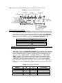
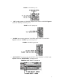
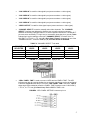
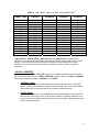
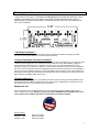
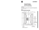
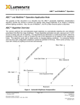
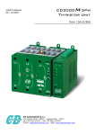
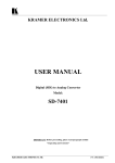
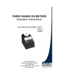
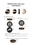
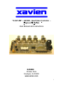
“X-QVC-EM” – XAVIEN - Quad Video Controller –
Engineering Module
User Manual and Instructions
XAVIEN
PO Box 7433
Goodyear, Az 85338
www.xavien.com
1
System Overview
The “X-QVC-EM” is a low cost 4-channel video multiplexer that was designed to allow the
integration and control of up to 4 video sources, these include cameras, RF video receivers and
RF video transmitters. The “X-QVC-EM” can either “scan” through each video channel
sequentially or can be set to a specific video channel locally (buttons / switches or RC receiver).
When the “X-QVC-EM” is set to “MANUAL” mode the user selects the video source by pressing
the corresponding button or setting the “EXT CTRL” bits. In “SCAN” mode the “X-QVC-EM”
switches between each video channel, starting with CH1, for a period of time set by the user (1s
to 16s in 1s increments). The “X-QVC-EM” has an input capacitance of 1pF whether the channel
is on or off providing a predictable input impedance to the signal source. Input and output ports
have all been optimized for 75 ohm, but will work with a wide range of inputs. The output is
capable of driving a 150 ohm load to within 730mV of the +5V power rails. DC input voltage can
range from +7V to +30V when using the “UNREG-DC” input. Camera connections are made
using “RCA” style connectors. This unit was designed to be used as a stand alone unit connected
to an external control system or mounted in a box as an independent system.
Specifications
DC INPUT
Dimensions
Video I/O Connectors
Camera Input
Adjustable Dwell Time
“UNREG-DC” INPUT: +7V to +30V
“+5V” INPUT: +4.75V to +5.25V
1.25” W x 3.8” L
RCA
1Vp-p, 75 oh
1s to 16s (in 1s increments)
Operational Overview
Figure 1 shows the “X-QVC-EM” assembly. There are 7 connectors used for interfacing to the
outside world. The “+5V” input connector should have +5V (+4.75V to +5.25V) and ground
applied to it. The “UNREG-DC” input connector can have a DC voltage ranging from +7V to +30V
applied since the “X-QVC-EM” has an onboard voltage regulator. ONLY one of the DC supplies
should be used at a time, do not attempt to power both connectors with a voltage. If you
are using the “UNREG-DC” input you can power an external circuit off of the “+5V” input line as
long as your load DOES NOT exceed 50mA.
FIGURE 1. “X-QVC-EM” Assembly
2
Figure 2 lists all associated connections on the “X-QVC-EM” and their functions.
FIGURE 2. Connections of “X-QVC-EM”
Control Interface Description:
•
To activate “RC RECEIVER CONTROL” mode place the included 2 pin jumper across
the “RC RECEIVER CONTROL” connector (to get out of this mode, remove jumper and
turn DC power to unit off ). Connect the output of your RC receiver to the “EXT CTRL”
connector with the signal (yellow or white wire) going to the “EXT CTRL ENABLE” pin.
Table 1. shows the truth table for using the “RC RECEIVER CONTROL” mode.
Pulse Time:
Video Channel Selected:
1.0ms to 1.25ms (Ideal: 1.1ms)
1.26ms to 1.5ms (Ideal: 1.4ms)
1.51ms to 1.75ms (Ideal: 1.6ms)
1.76ms to 2.0ms (Ideal: 1.9ms)
1
2
3
4
** NOTE: When the unit is in RC Receiver Control mode and the unit looses RC Signals, the
“X-QVC-EM” stays at the last video channel selected.
•
“EXT CTRL” (with the “RC RECEIVER CONTROL” jumper removed from unit) is used
to connect to an external controller for video channel select, sets the unit into “LOCAL”
control or “REMOTE” mode. In “LOCAL” control the system is controlled through the
other connections, “MODE SELECT”, “CHANNEL SELECT” and “LED / DWELL
TIME”. In “LOCAL” control the unit has two modes of operation (depending on the
“MODE SELECT” input), “MANUAL” and “SCAN”. When unit is put into “REMOTE”
mode it ignores all other functions except the “EXT CTRL” A0 / A1 signals. Table 2
shows logic levels needed to control the “EXT CTRL” functions on the “X-QVC-EM” (1 =
TTL Hi, 0 = TTL Low) (X = Don’t Care). Figure 3 shows the pin out of the “EXT CTRL”
connector.
TABLE 2. “EXT CTRL” Truth Table
ENABLE
A0
A1
CH Selected
0
1
1
1
1
X
0
1
0
1
X
0
0
1
1
X (”LOCAL” MODE)
CH1
CH2
CH3
CH4
3
FIGURE 3. “EXT CTRL” pin out
•
“+5V” is used to power the “X-QVC-EM”, range is from +4.75V to +5.25V DC. Figure 4
shows the “+5V” input connector pin out.
FIGURE 4. “+5V” input pin out
•
“UN-REG” input is used to power the “X-QVC-EM”, range is from +7V to +30V DC.
Figure 5 shows the “UN-REG” input connector pin out.
FIGURE 5. “UN-REG” input pin out
•
“MODE SELECT” is used to put the “X-QVC-EM” in either “MANUAL” or “SCAN” mode.
Figure 6 shows the “MODE SELECT” connector pin out.
FIGURE 6. “MODE SELECT” input pin out
4
•
“CH4 VIDEO IN” is used for video signal input (center conductor = video signal).
•
“CH3 VIDEO IN” is used for video signal input (center conductor = video signal).
•
“CH2 VIDEO IN” is used for video signal input (center conductor = video signal).
•
“CH1 VIDEO IN” is used for video signal input (center conductor = video signal).
•
“VIDEO OUTPUT” is used for video signal output (center conductor = video signal).
•
“CHANNEL SELECT” is used to manually select video channels. The “CHANNEL
SELECT” interface was designed to allow the user to easily connect momentary
switches for selecting a specific channel. To select a specific channel the “CHx SELECT”
pin must see a momentary TTL logic low (or momentarily short that pin to ground). Table
3 shows logic levels needed to control the “CHANNEL SELECT” functions of the “XQVC-EM” (1 = TTL Hi, 0 = TTL Low) (X = Don’t Care). Figure 7 shows the pin out of the
“CHANNEL SELECT” connector. Pins 2, 4, 6, and 8 are all tied to GROUND.
TABLE 3. “CHANNEL SELECT” Truth table
CHANNEL
SELECTED
CH1 LOGIC
LEVEL
CH2 LOGIC
LEVEL
CH3 LOGIC
LEVEL
CH4 LOGIC
LEVEL
1
2
3
4
0
1
1
1
1
0
1
1
1
1
0
1
1
1
1
0
FIGURE 7. “CHANNEL SELECT” input pin out
•
“LEDs / DWELL TIME” is used to connect 4 LEDs and set “DWELL TIME”. The LED
indicators can also be used as feedback to an external controller to monitor what channel
is selected. Figure 8 shows the pin out of the “LED / DWELL TIME” connector. Table 4
shows logic levels needed to control the “DWELL TIME” functions on the “X-QVC-EM” (1
= TTL Hi, 0 = TTL Low) (X = Don’t Care). Default DWELL TIME is 16s.
FIGURE 8. “LED / DWELL SETTING” connector pin out
5
TABLE 4. “LED / DWELL TIME” Truth table, setting DWELL TIME
DWELL TIME
1s DWELL
2s DWELL
4s DWELL
8s DWELL
1s
2s
3s
4s
5s
6s
7s
8s
9s
10s
11s
12s
13s
14s
15s
16s
1
0
1
0
1
0
1
0
1
0
1
0
1
0
1
0
0
1
1
0
0
1
1
0
0
1
1
0
0
1
1
0
0
0
0
1
1
1
1
0
0
0
0
1
1
1
1
0
0
0
0
0
0
0
0
1
1
1
1
1
1
1
1
0
“CH1 STATUS”, “CH2 STATUS”, “CH3 STATUS” and “CH4 STATUS” can be used as
indicators for monitoring selected channel. Each line has a series resistor (680 ohm) for current
limiting. You can also connect the anode of an LED directly to each status line for visible
indication. You can also connect the status lines directly to I/O lines of a MCU for system
monitoring.
“LOCAL” CONTROL:
When the ENABLE pin of the “EXT CTRL” input is left “OPEN” or placed at a LOGIC LEVEL 0
the “X-QVC-EM” enters into the “LOCAL” CONTROL operation. When in “LOCAL” CONTROL
there are two modes of operation, “MANUAL” and “SCAN”.
•
“MANUAL” Mode:
“MANUAL” mode is used to continuously view a specific channel. Once “X-QVC-EM”
powers up and senses “MANUAL” mode has been selected, CH1 is selected by default.
The unit will keep CH1 selected until the user selects a different channel.
•
“SCAN” Mode:
This mode allows the user to sequentially scan through each channel. The dwell time for
each channel is set by the user in 1s increments (1s MIN to 16s MAX). While the unit is
scanning the user can select a specific channel, the unit will stay on that channel as long
as the user has it selected.
6
Mounting / Installation
The “X-QVC-EM” comes standard with the following 0.1” (2.54mm) headers: 4x 2-pin, 1x 3-pin,
1x 8-pin and 1x 5x2 (10) pin. The headers are NOT soldered to the PCB; this allows the user to
install the connectors on the top or bottom of the PCB. This also allows the user to place a
different style of connector on the board or install wires directly to the PCB. All mounting holes
are 0.125” in diameter.
* Handling Precautions **
These units are sensitive to damage from ESD and should always be handled in a properly grounded
environment; damage from ESD is not covered under the warranty.
!! Product Disclaimer and Limit of Liability !!
Since the use and application of this equipment are beyond our control, the purchaser or user agrees to hold
“XAVIEN” and their agents from any and all legal claims, demands, actions, debts, liabilities, judgments,
costs and attorney fees arising out of, claimed on account of, or in any manner predicted upon loss or
damage to property of, or injuries to or death of, any and all persons arising out of the use of this equipment.
Due to the nature of electronic devices, the application and environments for these devices, the possibility of
failure can never be completely ruled out. It is the responsibility of the purchaser or user of this equipment to
properly test and simulate the actual conditions under which the device is intended to be used to ensure the
highest degree of reliability, safety and success.
!! Product Warranty !!
The “X-QVC-EM” has a warranty of 1 year starting from date of purchase as long as all the guidelines have
been followed that are outlined is this document. Any improper use or carelessness on the part of user will
void the warranty. If your unit has problems send an email to:
[email protected]
Once this has been done, XAVIEN will send you a return material authorization (RMA) number that you
need to include with your unit. DO NOT send any units back to XAVIEN without this RMA number, if we
receive product with no RMA it will NOT be accepted and mailed back unrepaired.
Revision History
PCB REV: 1.00A
DOC REV: 1.00A
FW REV: 1.00A
DATE: 07/15/2007
DATE: 07/15/2007
DATE: 07/15/2007
7