1
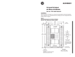
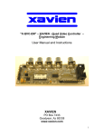
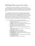
ABC™ and NiteBrite™ Operation ABC™ and NiteBrite™ Operation Application Note The purpose of this document is to describe how the ABC™ (automatic brightness compensation) algorithm controls the camera to achieve the desired mean target brightness of an image in changing ambient lighting conditions. Also, the use of NiteBrite™, the IR-cut filter removal option is described. ABC™ Algorithm Overview The camera achieves the user-selectable target brightness by automatically adjusting the user-selected parameters that affect the image brightness. These adjustable parameters are gain, exposure and, if a DC iris lens is being used, the iris opening. The adjustments are performed in a closed loop fashion, where the brightness of each frame is used to compute the size of the adjustment to be applied on the subsequent frame. This algorithm works well to adapt quickly to changing lighting conditions. It is extremely flexible and has many user configurable variables to control the operation of the loop. When tuned correctly, it can cope with virtually any lighting environment automatically. Gain Max. Gain t en i b Am D ht g Li ec as re g in Auto Gain Knee Max. Exposure Min. Exposure Min. Gain = 1 Iris Opening Auto Exposure Knee b Am L nt ie i tI gh n i as e cr ng Exposure Figure 1 - Automatic Brightness Compensation Proprietary and Confidential Lumenera 2005 Document number: LA-2114 Document revision and date: v1.03, Mar. 2005 Page 1 of 6 Lumenera Corporation 7 Capella Crt Ottawa, ON, Canada K2E 8A7 www.lumenera.com (613) 736 - 4077 ABC™ and NiteBrite™ Operation Automatic Brightness Compensation Algorithm Figure 1 depicts a graph that shows the path that the exposure, gain and iris values may follow as they are adjusted based on the changing ambient lighting conditions. Note that only one parameter is adjusted at a time, providing five distinct legs. Several points along the path are labeled. These are user configurable variables used to tune the performance of the control loop. They represent the transition points from one control parameter to the next and are described in more detail below. Controlling the Algorithm The algorithm can be tailored to match what is necessary for a specific application. This is accomplished by adjusting the various algorithm control variables. These variables can be used to lengthen or shorten or even eliminate the various legs that are seen on the graph in Figure 1. The Auto Exposure Knee and Auto Gain Knee points are used to indicate when to switch from using exposure to using gain (and vice versa) as the parameter that will be adjusted to change the image brightness. The Minimum Exposure variable acts as the transition point indicating at what exposure value the DC Iris will start to close down to reduce the image brightness. The Maximum Exposure variable is the maximum allowable exposure that the algorithm will use. It is also the point at which gain will again be used to control brightness. That is, it’s really another knee point. The actual variables are listed below. The names of the parameters listed match the names from the API manual located on the camera. exposure gain autoexposure_target autogain autoexposure autoiris autogain_knee autoexposure_knee minimum_exposure maximum_gain maximum_exposure Current exposure setting of the camera. Current gain setting of the camera. Desired target brightness of images from the camera. Boolean value to enable the automatic gain control. Boolean value to enable the automatic exposure control. Boolean value to enable the automatic DC Iris control Gain value at which the algorithm switches to adjusting exposure. Exposure value at which the algorithm switches to adjusting gain. Exposure value at which the algorithm switches to adjusting the iris. The maximum allowable gain to use in the algorithm. The maximum allowable exposure to use in the algorithm. Table 1 –Parameters used to Control the ABC™ algorithm The autoexposure_target is the target brightness that the camera tries to achieve by adjusting the control parameters. The average brightness that the camera computes is determined by the auto_algorithm parameter and the “auto window” parameters. These are explained fully in the user manual. The autogain, autoexposure and autoiris variables are used to enable or disable the automatic adjustment of the respective parameter thus providing a way to eliminate the respective leg completely. When autogain or autoexposure are disabled, the gain or exposure is held fixed to their current value but either can still be manually adjusted in that case. Proprietary and Confidential Lumenera 2005 Document number: LA-2114 Document revision and date: v1.03, Mar. 2005 Page 2 of 6 Lumenera Corporation 7 Capella Crt Ottawa, ON, Canada K2E 8A7 www.lumenera.com (613) 736 - 4077 ABC™ and NiteBrite™ Operation Typical ABC™ Operation Assuming all three control parameters are enabled and starting in a very bright environment, the camera will have minimum gain and exposure settings and the DC iris will be small. This is the lower left point on the graph in Figure 1. As the light levels decrease, the iris will start to open in an attempt to make the video images reach the target brightness. If the target cannot be achieved, the iris continues to open until it reaches its fully open state. If the target is still not achieved, the exposure then starts to increase until it reaches the value of the Auto Exposure Knee. At that point, if more brightness is still needed, the gain starts to increase until it reaches a value of the Auto Gain Knee. Again if the target is still not achieved, the exposure is again increased until it reaches its Maximum Exposure value. Finally, if more brightness is still needed, the gain is again increased until it reaches its Maximum Gain value. When starting in a dark environment and as ambient light increases, the operation of the algorithm is the reverse of the above. Control Parameter Tradeoffs There is a very good reason for having the exposure and gain each have two legs. As the gain is increased, noise is introduced into the image. As the exposure is increased, motion blur is introduced into the images and if the exposure exceeds the maximum frame rate period, the frame rate will decrease. The intent is to use the lower gain and exposure legs as the normal mode of operation where the maximum low light performance can be obtained without visible effects from noise, motion blur and without affecting frame-rate. The higher gain and exposure legs are used to extract the maximum performance from the camera when image quality and frame rate can be sacrificed. It is impossible to define a single set of parameters that will work in all situations. Each application is more or less sensitive to noise, blur and frame-rate. However, the following guidelines can be used to set parameters depending on the needs of the application. Avoiding Motion Blur Auto Exposure Knee should be set to 20 ms or less when motion blur is to be minimized during normal operation. The Maximum Exposure should be set to the same value if you want to avoid motion blur completely. Alternatively, if a DC Iris lens is being used, the Auto Exposure can be disabled and the Exposure value set to 20 ms or less. If a DC Iris lens is not being used, the minimum exposure should be set as low as possible to allow very bright lighting to be handled. Avoiding Noisy Images Auto Gain Knee should be set to 5 or less when noise is to be minimized during normal operation. Maximum Gain should be set to the same value to completely avoid noise in the images. Alternatively, the Auto Gain can be disabled and the Gain value set to some fixed value less than 5 or so. Proprietary and Confidential Lumenera 2005 Document number: LA-2114 Document revision and date: v1.03, Mar. 2005 Page 3 of 6 Lumenera Corporation 7 Capella Crt Ottawa, ON, Canada K2E 8A7 www.lumenera.com (613) 736 - 4077 ABC™ and NiteBrite™ Operation Avoiding Decreased Frame-Rate To avoid having the frame rate decrease due to the automatic changing of the exposure, the Maximum Exposure can be set to a value less than or equal to the maximum frame-rate period. Because this value is different depending on the window size used, the Maximum Exposure can be set to the value of zero, which has the special meaning of 'limit the camera to exposures that do not slow down the frame rate'. When using this value, the Auto Exposure Knee should be set to a value that is less than the maximum framerate period otherwise the Auto Exposure Knee will never be reached and the automatic gain leg will not be utilized. NiteBrite™ Operation Day/Night Ethernet cameras are equipped with the NiteBrite™ option, an automatically removable IR-cut filter. This option provides an advantage over regular cameras when used at night or in other low light conditions. It allows the camera to provide proper color images in normal light conditions by utilizing the IR-cut filter but at night or when light levels are low, it automatically moves the IR-cut filter out of the way, replacing it with a plain glass window, improving the sensitivity and allowing the use of near-IR illumination for true zero lux (visible) operation. Manual control of the filter movement is also available. NiteBrite™ Thresholds and Oscillation The camera uses the normal and low-light thresholds to control the NiteBrite™ feature. These thresholds consist of Boolean expressions that can include the camera’s exposure and gain. For example, a low light threshold might be: Exposure > 30 AND Gain > 5 The camera will require that the threshold be met for a specified duration (settling period) before applying the appropriate list of user-defined settings. These settings would include exchanging the IR-cut filter and plain glass window. The settling period avoids reacting to transient events that should be ignored. When configured appropriately, under low light conditions a high exposure and gain will cause the camera to switch to low-light mode removing the IR-cut filter. If, in this situation near-IR light is present, a significant drop in the exposure and gain values will occur. This could lead to the triggering of normal mode, which would move the IR-cut filter back into place. This would block the near-IR light potentially triggering low-light mode again. This oscillation could continue indefinitely. To avoid the continuous oscillation between the two modes, it may be necessary to experiment with appropriate threshold settings and durations. Alternatively, the automatic nature of NiteBrite™ could be disabled and the IR-cut filter and glass window exchange performed manually. Configuring NiteBrite™ The general low-light configuration parameters are listed below. The names of the parameters listed match the names from the API manual located on the camera. Similar names are used for the same parameters accessible from the web page. Proprietary and Confidential Lumenera 2005 Document number: LA-2114 Document revision and date: v1.03, Mar. 2005 Page 4 of 6 Lumenera Corporation 7 Capella Crt Ottawa, ON, Canada K2E 8A7 www.lumenera.com (613) 736 - 4077 ABC™ and NiteBrite™ Operation ir_shuttle_position low_light_criteria normal_light_criteria low_light_settings normal_light_settings low_light_stable_duration normal_light_stable_duration The position of the IR filter. 0 = normal (IR-cut filter), 1 = low light (plain glass) The low light threshold. This is a Boolean expression. The normal light threshold. This is a Boolean expression. Camera changes applied in low light mode (including moving the IR filter). Camera changes applied in normal light mode (including moving the IR filter). The low light threshold must be true for this period to switch to low light mode. The normal light threshold must be true for this period to switch to normal mode. Table 2 –Parameters used to configure the NiteBrite™ Feature Default Configuration of Day Night Cameras The default configuration of the camera assumes that the camera is to be installed outdoors with ambient night-time IR lighting. The exposure knee is set to 26ms with the normal and low light criteria set to 10ms and 30ms respectively. This configuration limits the cameras exposure to minimize motion blur. In the case that IR lighting is not present; the day night algorithm is designed to increase the exposure and gain to their maximum values. This is used as a fallback in the case of an IR lighting failure. autoexposure_knee autogain_knee low_light_criteria normal_light_criteria low_light_settings normal_light_settings low_light_stable_duration normal_light_stable_duration maximum_gain maximum_exposure 26 100 exposure > 30 exposure < 10 ir_shuttle_position=1,saturation=-100,lighting_frequency=60 ir_shuttle_position=0,saturation=0,lighting_frequency=dc 10 10 300 500 Table 3 – Default Day Night Camera Configuration This setup allows for an exposure range of 20ms and a 100x gain between the normal and low-light thresholds. This range is easily adjustable by changing the autogain_knee to optimize the lighting level at which the camera will switch to night mode. The low-light settings are also optimized for IR lighting. The color noise seen from the black-white images is removed by setting the saturation to its minimum value. As well, IR light sources might use AC or DC power. The camera can be configured to lock its exposure to an AC-powered IR light source by only using 50Hz or 60Hz harmonics. This can be done using the lighting_frequency parameter. Proprietary and Confidential Lumenera 2005 Document number: LA-2114 Document revision and date: v1.03, Mar. 2005 Page 5 of 6 Lumenera Corporation 7 Capella Crt Ottawa, ON, Canada K2E 8A7 www.lumenera.com (613) 736 - 4077 ABC™ and NiteBrite™ Operation Disclaimer Lumenera Corporation reserves the right to make corrections, modifications, enhancements, improvements, and other changes to its products and services at any time and to discontinue any product or service without notice. Customers should obtain the latest relevant information before placing orders and should verify that such information is current and complete. All products are sold subject to Lumenera Corporation’s terms and conditions of sale supplied at the time of order acknowledgment. Lumenera Corporation warrants performance of its hardware products to the specifications applicable at the time of sale in accordance with Lumenera Corporation’s standard warranty. Testing and other quality control techniques are used to the extent Lumenera Corporation deems necessary to support this warranty. Except where mandated by government requirements, testing of all parameters of each product is not necessarily performed. Lumenera Corporation assumes no liability for applications assistance or customer product design. Customers are responsible for their products and applications using Lumenera Corporation components. To minimize the risks associated with customer products and applications, customers should provide adequate design and operating safeguards. Lumenera Corporation does not warrant or represent that any license, either express or implied, is granted under any Lumenera Corporation patent right, copyright, mask work right, or other Lumenera Corporation intellectual property right relating to any combination, machine, or process in which Lumenera Corporation products or services are used. Information published by Lumenera Corporation regarding third–party products or services does not constitute a license from Lumenera Corporation to use such products or services or a warranty or endorsement thereof. Use of such information may require a license from a third party under the patents or other intellectual property of the third party, or a license from Lumenera Corporation under the patents or other intellectual property of Lumenera Corporation. Reproduction of information in Lumenera Corporation data books or data sheets is permissible only if reproduction is without alteration and is accompanied by all associated warranties, conditions, limitations, and notices. Reproduction of this information with alteration is an unfair and deceptive business practice. Lumenera Corporation is not responsible or liable for such altered documentation. Resale of Lumenera Corporation products or services with statements different from or beyond the parameters stated by Lumenera Corporation for that product or service voids all express and any implied warranties for the associated Lumenera Corporation product or service and is an unfair and deceptive business practice. Lumenera Corporation is not responsible or liable for any such statements. Proprietary and Confidential Lumenera 2005 Document number: LA-2114 Document revision and date: v1.03, Mar. 2005 Page 6 of 6 Lumenera Corporation 7 Capella Crt Ottawa, ON, Canada K2E 8A7 www.lumenera.com (613) 736 - 4077