1
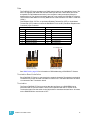
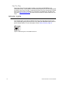
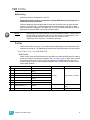
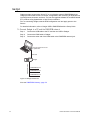
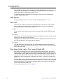
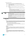
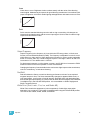
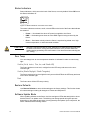
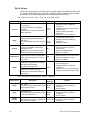
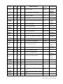
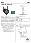
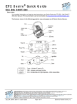
Desire® Series by ETC D40/D60 XTI User Manual v1.6 Rev A Read entire User Manual before using equipment. Copyright © 2013 Electronic Theatre Controls, Inc. A l l R i g h t s r es e r v e d . P r o d u c t i n f o r m a t i o n a n d s p e c i fi c a t i o n s s u b j e c t to c h a n g e . P a r t N u m b e r : 7410M1250-1.6.0 R e v A R e l e a s e d : 2 0 14 - 0 2 E T C p e r m i ts t h e r e p r o d u c t i o n o f m a t e r i a l s i n t h i s m a n u a l o n l y f o r n o n - c o m me r c i a l p u r p o s e s . A l l o t h e r r i g ht s a r e r e s e r v e d b y E T C . E T C i n t e n d s t hi s d o c u m e n t , w h e t h e r p r i n te d o r e l e c t r o n i c , t o b e p r o v i d e d i n i t s e n t i r e ty . E T C a n d D e s i r e a r e r e g i s t e r e d tr a d e m a r k s o f E le c tr o n i c T h e a t r e C o n t r o l s , I n c . i n t h e U n i t e d S t a t e s a n d o t h e r c o u n tr i e s . O t h e r p r o d u c t a n d c o m p a n y n a m e s m e n t i o n e d h e r e i n m a y b e t r a d em a r k s a n d /o r s e r v i c e m a r k s of their respective owners. T h i s p r o d u c t i s p r o t e c t e d b y o n e o r m o r e o f t h e f o l l o w i n g U . S . P a t e n ts : 6 , 0 1 6 , 03 8 , 6 , 1 5 0 ,7 7 4 , 6 ,7 8 8 , 0 1 1 , 6 , 8 06 , 6 5 9 , 6 , 6 8 3 ,4 2 3 a n d 7 , 0 2 3 ,5 4 3 Table of Contents Introduction . . . . . . . . . . . . . . . . . . . . . . . . . . 1 Quick Setups . . . . . . . . . . . . . . . . . . . . . . . . . . . . . . . . . . . . . . . . . . .1 Vivid, Lustr+, Fire, Ice and Studio HD . . . . . . . . . . . . . . . . . . . . . .1 Studio Daylight, Studio Tungsten . . . . . . . . . . . . . . . . . . . . . . . . .2 Models . . . . . . . . . . . . . . . . . . . . . . . . . . . . . . . . . . . . . . . . . . . . . . . .3 Applications . . . . . . . . . . . . . . . . . . . . . . . . . . . . . . . . . . . . . . . . . . . .3 Compliance . . . . . . . . . . . . . . . . . . . . . . . . . . . . . . . . . . . . . . . . . . . .4 Document Conventions . . . . . . . . . . . . . . . . . . . . . . . . . . . . . . . . . . .4 Notices . . . . . . . . . . . . . . . . . . . . . . . . . . . . . . . . . . . . . . . . . . . . .4 Typography Used in This Guide . . . . . . . . . . . . . . . . . . . . . . . . . .4 Safety . . . . . . . . . . . . . . . . . . . . . . . . . . . . . . . . . . . . . . . . . . . . . . . . .5 Contacts . . . . . . . . . . . . . . . . . . . . . . . . . . . . . . . . . . . . . . . . . . . . . . .6 Chapter 1 Installation and DMX Profiles . . . . . . . . . . . . 7 Specifications . . . . . . . . . . . . . . . . . . . . . . . . . . . . . . . . . . . . . . . . . . .8 Dimensions and Clearances . . . . . . . . . . . . . . . . . . . . . . . . . . . . .9 Fixture Weight . . . . . . . . . . . . . . . . . . . . . . . . . . . . . . . . . . . . . . . .9 Installation Clearances . . . . . . . . . . . . . . . . . . . . . . . . . . . . . . . .10 Typical Power Consumption D40XTI . . . . . . . . . . . . . . . . . . . . .11 Typical Power Consumption D60XTI . . . . . . . . . . . . . . . . . . . . .11 Note About LED Fixtures. . . . . . . . . . . . . . . . . . . . . . . . . . . . . . .13 Color Rendering Index and Color Quality Scale Ratings . . . . . .13 Installation . . . . . . . . . . . . . . . . . . . . . . . . . . . . . . . . . . . . . . . . . . . .14 Installation on a Pipe . . . . . . . . . . . . . . . . . . . . . . . . . . . . . . . . . .14 Accessory Installation . . . . . . . . . . . . . . . . . . . . . . . . . . . . . . . . .16 Installation on a Permanent Base . . . . . . . . . . . . . . . . . . . . . . . .16 Installation on a Pole . . . . . . . . . . . . . . . . . . . . . . . . . . . . . . . . . .16 Installation on a Wall . . . . . . . . . . . . . . . . . . . . . . . . . . . . . . . . . .17 Power and Data Cabling Requirements . . . . . . . . . . . . . . . . . . .17 Indicator Lights . . . . . . . . . . . . . . . . . . . . . . . . . . . . . . . . . . . . . . . . .19 DMX Profile . . . . . . . . . . . . . . . . . . . . . . . . . . . . . . . . . . . . . . . . . . .20 Addressing . . . . . . . . . . . . . . . . . . . . . . . . . . . . . . . . . . . . . . . . .20 Profiles . . . . . . . . . . . . . . . . . . . . . . . . . . . . . . . . . . . . . . . . . . . .20 DMX Footprints and Channel Mapping . . . . . . . . . . . . . . . . . . . . . .24 Vivid, Lustr+, Fire, Ice, Studio HD . . . . . . . . . . . . . . . . . . . . . . . .24 Studio Tungsten and Daylight . . . . . . . . . . . . . . . . . . . . . . . . . . .24 Chapter 2 Operation . . . . . . . . . . . . . . . . . . . . . . . . . . 25 Overview . . . . . . . . . . . . . . . . . . . . . . . . . . . . . . . . . . . . . . . . . . . . .26 Gadget . . . . . . . . . . . . . . . . . . . . . . . . . . . . . . . . . . . . . . . . . . . . . . .27 Desire XTI Series v1.6.0 User Manual i DMX/RDM Gateway . . . . . . . . . . . . . . . . . . . . . . . . . . . . . . . . . . . . .28 Configuration . . . . . . . . . . . . . . . . . . . . . . . . . . . . . . . . . . . . . . . . . .29 DMX Address . . . . . . . . . . . . . . . . . . . . . . . . . . . . . . . . . . . . . . .29 Data Loss . . . . . . . . . . . . . . . . . . . . . . . . . . . . . . . . . . . . . . . . . .29 Plus Seven (Vivid, Lustr+, Fire, Ice, and Studio HD) . . . . . . . . .29 LED Settings . . . . . . . . . . . . . . . . . . . . . . . . . . . . . . . . . . . . . . . .30 Status Indicators . . . . . . . . . . . . . . . . . . . . . . . . . . . . . . . . . . . . .33 Over Temp . . . . . . . . . . . . . . . . . . . . . . . . . . . . . . . . . . . . . . . . .33 Restore Defaults . . . . . . . . . . . . . . . . . . . . . . . . . . . . . . . . . . . . .33 Software Update Mode . . . . . . . . . . . . . . . . . . . . . . . . . . . . . . . .33 Presets and Sequences . . . . . . . . . . . . . . . . . . . . . . . . . . . . . . . . . .34 Presets . . . . . . . . . . . . . . . . . . . . . . . . . . . . . . . . . . . . . . . . . . . .34 Sequences . . . . . . . . . . . . . . . . . . . . . . . . . . . . . . . . . . . . . . . . .36 Appendix A Quick Start . . . . . . . . . . . . . . . . . . . . . . . . . 38 Install . . . . . . . . . . . . . . . . . . . . . . . . . . . . . . . . . . . . . . . . . . . . .38 Focus. . . . . . . . . . . . . . . . . . . . . . . . . . . . . . . . . . . . . . . . . . . . . .38 Configure. . . . . . . . . . . . . . . . . . . . . . . . . . . . . . . . . . . . . . . . . . .38 Quick Setups . . . . . . . . . . . . . . . . . . . . . . . . . . . . . . . . . . . . . . . .39 Appendix B RDM Commands . . . . . . . . . . . . . . . . . . . . 40 ii Introduction Congratulations on your purchase of a Desire Series D40/D60 XTI fixture by ETC. The Desire XTI Series is designed for permanent installations indoors or outdoors, with an IP66 rating, rugged die-cast enclosure, and noiseless fan-free operation. Up to 32 Desire XTI fixtures can be linked together on one data chain and configured over a DMX/RDM network. Desire’s x7 Color System™ seven-hue technology produces a light and color quality that conventional LED systems cannot duplicate. This unique color system produces bright, broad-spectrum whites and intense colors equally well, rendering pigments, objects, and skin tones in a natural way. Fire and Ice fixtures use elements of the x7 Color System for superior performance in deep saturated colors. Studio Daylight and Studio Tungsten fixtures use high-output white LEDs for maximum brightness and efficacy. Studio Tungsten interacts very well with incandescent sources, while Studio Daylight easily replaces a variety of HMI lamps and natural sunlight. Quick Setups You can use any one of the Quick Setups and fine-tune settings for operation via DMX/RDM protocol. Vivid, Lustr+, Fire, Ice and Studio HD Some of the options include: 1 • Multiple DMX profiles ranging from a simple 3-channel RGB profile to 8-channel native color and intensity control. • Multiple dimming curve options. • Preset colors and sequences for standalone operation. • White point selection; white light and color behavior based on a specific color temperature white light such as 3200K or 5600K. • Loss-of-data behavior options. • Power regulation modes; three output options that offer a choice between maximum light output for lower duty cycles and maximum thermal stability and output consistency for higher duty cycles. Desire XTI Series v1.6.0 User Manual Studio Daylight, Studio Tungsten Some of the options include: • Multiple dimming curve options. • Presets and sequences for standalone operation. • Strobe. • Loss-of-data behavior options. • Power regulation modes; three output options that offer a choice between maximum light output for lower duty cycles and maximum thermal stability and output consistency for higher duty cycles. Yoke Yoke locking bolt Trim ring LED array Safety cable loop Figure-1.1 Components of a D40/D60 XTI Fixture. Power in DMX/RDM in and thru Status indicators Figure-1.2 Components of the Rear Panel. Introduction 2 Models Each member of the Desire Series product line is unique and optimized for a specific lighting task. All fixtures feature narrow optics for the longest throws. Vivid • Full 7-color x7 LED array • Optimized for high-output deep pastels and strong saturated colors—an all-around workhorse for vibrant color washes Lustr+ • Specialized x7 LED array with 6 colors plus white • Broad-spectrum color optimized for the best white and light tints across the entire white and pastel range • Beautifully illuminates skin tones and other objects—ideal for theatrical lighting Fire • Optimized for saturated colors at the red end of the spectrum • Strongest output for high-intensity washes and theatrical environments Ice • Optimized for saturated colors at the blue end of the spectrum • Strongest output for high-intensity washes and theatrical environments Studio HD • Precise mix of warm white and cool white LEDs plus additional strategic colors for more spectral power • Continuously variable color temperature white light • Extreme CRI and high-definition illumination of skin tones from 2700K to 6500K Studio Daylight • 5,700K nominal correlated color temperature • 70 CRI typical Studio Tungsten • 3,000K nominal correlated color temperature • 85 CRI typical Appl ications • • • • 3 Houses of worship Museums Theme parks Commercial buildings • Outdoor signage • Outdoor performance venues • Public sculptures Desire XTI Series v1.6.0 User Manual Compliance The Desire D40/D60XTI Series fixture complies with and has been tested to the following regulatory standards: • ETL Listed to UL 1598 USA / CSA C22.2 No. 250.0-08 Canada • CE EN55015:2006 + A1:2007 / EN55022:2006 + A1:2007 Class B / EN61000-3-2:2006 + A2:2009 / EN61000-3-3:2008 / EN61547:1996 + A1:2000 Document Conventions Notices Throughout this manual, the following are used to alert you to notes and safety notices. Note: Notes are helpful hints and information that is supplemental to the main text. CAUTION: A Caution statement indicates situations where there may be undefined or unwanted consequences of an action, potential for data loss or an equipment problem. WARNING: Warning statement indicates situations where damage may occur, people may be harmed, or there are serious or dangerous consequences of an action. WARNING: RISK OF ELECTRIC SHOCK! This warning statement indicates situations where there is a risk of electric shock. Typography Used in This Guide Menu items and commands you must perform are indicated in bold text. For example: Using an RDM configuration tool, select Off to turn the Status Indicators off. Introduction 4 Safety The Desire series fixtures are intended for professional use only. Read entire User Manual before using equipment. WARNING: 5 Note the following safety warnings before use: • Do not mount the Desire XTI fixture on or near a flammable surface. • Mount and support the fixture only by the primary suspension holes in the yoke or mounting brackets. • Mount the fixture from a suitable structure using only the hardware rated for the weight of the fixture. • In addition to primary suspension, attach a safety cable (ETC Model 400SC or other approved safety cable or device) to the fixture housing. Appropriate attachment point (hole) is provided in the protruding tab on the fixture housing. • Disconnect the unit from power before all cleaning and maintenance. • Maximum recommended ambient operating temperature: Ta=40°C (104°F) • Maximum anticipated external surface temperature: Tmax=80°C (158°F) • External temperature after 5 minutes of full-brightness operation and 23°C (74°F) ambient: 38°C (100°F) • External Temperature (steady state achieved) at 23°C (74°F): 70°C (158°F) Desire XTI Series v1.6.0 User Manual Contacts If you have questions about your Desire series fixture that are not answered in this manual, please contact the supplier of your ETC equipment or ETC Technical Services. For general information, your most convenient resources are the references provided in this manual. To search more widely try the ETC web site at www.etcconnect.com. For technical questions about Desire Series fixtures, contact ETC Technical Services directly at one of the offices listed below. Emergency service is available from all ETC offices outside of normal business hours. Americas Electronic Theatre Controls Inc. Technical Services Department 3031 Pleasant View Road Middleton, WI 53562 800-775-4382 (USA, tollfree) +1-608 831-4116 [email protected] Asia United Kingdom Electronic Theatre Controls Ltd. Technical Services Department 26-28 Victoria Industrial Estate Victoria Road, London W3 6UU England +44 (0)20 8896 1000 [email protected] Germany Electronic Theatre Controls Asia, Ltd. Technical Services Department Room 1801, 18/F Tower 1, Phase 1 Enterprise Square 9 Sheung Yuet Road Kowloon Bay, Kowloon, Hong Kong +852 2799 1220 [email protected] Electronic Theatre Controls GmbH Technical Services Department Ohmstrasse 3 83607 Holzkirchen, Germany +49 (80 24) 47 00-0 [email protected] Please email comments about this manual to: [email protected] Introduction 6 Chapter 1 Installation and DMX Profiles This chapter contains the following sections: 7 • Specifications. . . . . . . . . . . . . . . . . . . . . . . . . . . . . . . . . . . . . . .8 • Installation . . . . . . . . . . . . . . . . . . . . . . . . . . . . . . . . . . . . . . . .14 • Indicator Lights . . . . . . . . . . . . . . . . . . . . . . . . . . . . . . . . . . . .19 • DMX Profile. . . . . . . . . . . . . . . . . . . . . . . . . . . . . . . . . . . . . . . .20 • DMX Footprints and Channel Mapping . . . . . . . . . . . . . . . . .24 Desire XTI Series v1.6.0 User Manual Specifications Physical • Rugged die-cast aluminum construction • Advanced thermal management systems for long LED life • Easy-to-remove trim ring for accessories • Ambient operating temperature -20 to 40 °C (-4 to 104 °F) • Continuous operation at 40 °C (104 °F) • Stainless steel mounting yoke • Available in black (standard), white (optional), silver, or custom colors (contact factory) • Rated IP66 for exterior use • No-noise, fan-free convection cooling for acoustically sensitive installations • See Fixture Weight, page 9 Electrical • 100V to 240V 50/60 Hz universal power input • Requires power from non-dim source • Up to 32 fixtures may be linked on one data chain • LEDs • 40 or 60 Luxeon® Rebel™ LED emitters (Vivid, Lustr+, • 40 or 60 Luxeon® Rebel™ ES LED emitters (Studio Fire, Ice, and Studio HD) Daylight and Studio Tungsten) • 50,000 hr. LED life (50,000 hours to 70% intensity) • See Note About LED Fixtures, page 13 Optical • Tight primary field angle of 17° (Vivid, Lustr+, Fire, Ice, and Studio HD) • Tight primary field angle of 24° (Studio Daylight and Studio Tungsten) • Secondary lenses available for multiple beam spread options including round, oblong, and linear patterns • Combine linear lenses for desired beam spread Color • Specialized capabilities from different LED array options based on x7 color-mixing expertise: – Vivid – Optimized for strong, saturated colors at maximum brightness – Lustr+ – x7 Color System array with a high-intensity white LED for an ideal theatrical wash light Full range color, with an emphasis on lighter colors and white – Fire and Ice – Optimized for high-intensity saturated colors in either the warm, red end of the spectrum (Fire) or the cool, blue end of the spectrum (Ice) – Studio HD — Optimized for variable color temperature white light • Interacts seamlessly with conventional sources • Achieves excellent 3200° or any other Correlated Color Temperature white light from 2000 to 10,000°K (except Fire or Ice) (CCT adjustment not available on Studio Daylight and Studio Tungsten) • Beautifully illuminates skin tones and other objects • Deeply saturated colors across an exceptionally wide gamut Control • DMX512-A compliant • DMX in via 6 foot cord and supplied DMX termination board • RDM functionality for address and setting changes and playing presets • Console-free presets and sequences via RDM device • Multiple profile options for different levels of control 1 Installation and DMX Profiles • Optional strobe channel • Master/slave mode • 15-bit virtual dimming engine for smooth, high-quality theatrical fades • See DMX Profile, page 20 8 Dimensions and Clearances Use the following dimensions to allow proper clearances around the fixture. Allow additional space for cables. D40XTI 17.7" 450mm 13.3" 338mm 8.3" 211mm 4.1" 105mm 19.1" 486mm 14.7" 373mm 4.5" 114mm 11.6" 294mm 5.6" 141mm 7.1" 180mm 8.5" 216mm 11.0" 278mm D60XTI 18.6" 474mm 14.2" 361mm 9.7" 246mm 20.5" 16.1" 521mm 408mm 12.8" 325mm 9.2" 234mm 4.5" 114mm 4.8" 123mm 7.3" 186mm 9.9" 251mm 10.6" 270mm 12.0" 305mm Figure-1.1 D40/D60 XTI Dimensions. Fixture Weight Total weight depends on how the individual fixture is configured. Model D40XTI D60XTI Weighta Lbs. Kg. 15 6.8 23 10.43 Shipping Weight Lbs. 18 24.7 Kg. 8.2 11.2 a) Does not include mounting hardware. 9 Desire XTI Series v1.6.0 User Manual Installation Clearances Cooling and Duty Cycle The D40/D60 XTI fixture is convection cooled and can operate all channels at full power continuously in ambient temperatures up to 40°C (104°F). If ambient conditions exceed 40°C (104°F) or fail to allow sufficient airflow, over a long period of time, the fixture may shut down and remain off until they return to a safe operating temperature. The fixture provides two methods to indicate over temperature: CAUTION: • Visible: The LED array glows in a dull, low intensity with only some emitters illuminated and the Error Indicator light turns on. • Dark: The LED array turns off. Duty Cycle Operating the fixture in higher ambient temperatures or low-airflow situations may cause the power supply to shut down. Following a cool-down period, the power supply will automatically reset and the fixture will return to operation. It is good practice to power down any device with on-board electronics to limit unnecessary wear on the devices and eliminate residual use of electricity. When not in use, Desire fixtures should be powered down by disconnecting from power at the breaker. LED life is adversely affected by high-temperature operation. When operating under elevated ambient temperatures, avoid turning all channels to 100% for extended periods, such as channel checks or focusing. 1 Installation and DMX Profiles 10 Typical Power Consumption D40XTI Vivid Idle Power / Current 100% Boost Power / Current 100V 10.5W / 0.135A 102W / 1.12A 120V 11W / 0.098A 98W / 0.82A 240V 12.7W / 0.078A 95.6W / 0.403 Idle Power / Current 100% Boost Power / Current 100V 10.3W / 0.125A 104W / 1.16A 120V 10.5W / 0.094A 102W / 0.861 240V 12.2W / 0.074A 99.7 W / 0.418 Idle Power / Current 100% Boost Power / Current 100V 10.5W / 0.125A 91.2W / 1.02A 120V 10.8W / 0.096A 88.2W / 0.74A 240V 12.5W / 0.076A 87.2W / 0.369A Idle Power / Current 100% Boost Power / Current 100V 11.0W / 0.123A 104.2W / 1.17A 120V 11.2W / 0.099A 102.2W / 0.867A 240V 12.8W / 0.077A 99.5W / 0.42A 100V 11.1W / 0.134A 106.2W / 1.19A 120V 11W / 0.097 A 103.5W / 0.883A 240V 12.8W / 0.077A 101.3W / 0.426A 100V 10.6W / 0.123A 105.1W / 1.12A 120V 10.6W / 0.095A 103.3W / 0.878A 240V 12.4W / 0.076A 100.8W / 0.424A 100V 10W / 0.111A 104W / 1.05A 120V 10.1W / 0.093A 103.1W / 0.872A 240V 11.9W / 0.075A 100.3W / 0.422A Lustr+ Fire Ice Studio HD Idle Power / Current 100% Boost Power / Current Studio Daylight Idle Power / Current 100% Boost Power / Current Studio Tungsten Idle Power / Current 100% Boost Power / Current Typical Power Consumption D60XTI Vivid Idle Power / Current 100% Boost Power / Current 100V 4.2W / 0.08A 117.9W / 1.19A 120V 4.3W / 0.075A 118W / 1A 240V 4.1W / 0.067A 115.6W / 0.526 Idle Power / Current 100% Boost Power / Current 100V 4.2W / 0.08A 123.7W / 1.24A 120V 4.2W / 0.075A 123.6W / 1.04 240V 4.3W / 0.069A 121W / 0.546 Idle Power / Current 100% Boost Power / Current 100V 4.2W / 0.08A 108.8W /1.1A 120V 4.3W / 0.075A 108.4W / 0.92A 240V 4.2W / 0.067A 106.2W/ 0.491A Lustr+ Fire 11 Desire XTI Series v1.6.0 User Manual Ice Idle Power / Current 100% Boost Power / Current 100V 4.2W / 0.08A 129.W / 1.26A 120V 4.2W /0.075A 124.4W / 1.05A 240V 4.3W / 0.068A 121.8W / 0.55A 100V 4.2W / 0.08A 125.1W / 1.26A 120V 4.3W / 0.76 A 124.7W / 1.05A 240V 4.3W / 0.068A 122.5W / 0.552A 100V 4.2W / 0.08A 125.1W / 1.26A 120V 4.3W / 0.76 A 124.7W / 1.05A 240V 4.2W / 0.068A 122.5W / 0.552A 100V 4.3W / 0.08A 124.4W / 1.25A 120V 4.2W / 0.073A 123.7W / 1.04A 240V 4.2W / 0.065A 121.2W / 0.545A Studio HD Idle Power / Current 100% Boost Power / Current Studio Daylight Idle Power / Current 100% Boost Power / Current Studio Tungsten Idle Power / Current 100% Boost Power / Current 1 Installation and DMX Profiles 12 Note About LED Fixtures All LED sources experience some lessening of light output and some color shift over time. Desire Series fixtures have complex thermal management systems to minimize these changes. With typical usage, a Desire fixture will still achieve at least 70% of its initial output after 50,000 hours of use (B50, L70). In individual situations, LEDs will be used for different durations and different levels. This can eventually lead to minor alterations in color performance, necessitating slight adjustment to presets, cues, or programs. All LEDs may exhibit a slight shift in output as they rise to full operating temperature. Desire Series fixtures allow the selection of different power settings in order to balance the competing requirements of thermal stability and brightness. Depending on the selected setting, changes in output as fixtures warm up may or may not be visible to the eye. Color Rendering Index and Color Quality Scale Ratings Desire fixtures are evaluated for Color Rendering Index (CRI) and Color Quality Scale (CQS) performance using measured output spectrum and optimized mix solutions for a best spectral match to black body sources at 3200K and 5600K. Color fidelity was also measured. These numbers may fluctuate slightly from fixture to fixture. This is a normal characteristic of white LEDs, and this kind of variation is highly unlikely to be apparent in most applications. The performance is the same for all fixture versions. Fixture Vivid at 3200K Vivid at 5600K Lustr+ at 3200K Lustr+ at 5600K Studio HD at 3200K Studio HD at 5600K Studio Tungsten at 3000K Studio Daylight at 5600K CRI 87 90 86 93 89 92 86 71 CQS 89 92 88 92 90 94 86 70 Color Fidelity 89 92 88 90 91 94 86 69 Duv 0.000 0.000 0.000 0.000 0.000 0.000 0.001 0.001 Desire luminaires provide excellent color rendering, particularly the color-mixing versions. A Duv rating of 0.000 indicates that the color mix used was exactly on the black body line, with no green or magenta tint. Studio Daylight and Studio Tungsten fixtures use only white-type LEDs at a fixed color temperature in order to maximize output and efficacy. 13 Desire XTI Series v1.6.0 User Manual Installation The D40/D60 XTI fixtures can be mounted four ways. • On a pipe with a C-clamp • On a permanent base • On a pole • On a wall Install on pipe or a suitable, rigid, permanent base with secured bolts. This can include poured concrete pads, factory-supplied pole-top and wall-mount brackets, and other attachments which meet the published weight and wind-load requirements for the fixture. Model D40XTI D60XTI Weighta Lbs. Kg. 15 6.8 23 10.43 Shipping Weight Lbs. 18 24.7 Kg. 8.2 11.2 Wind Rating .72 EPA .95 EPA a) Does not include mounting hardware. Detailed installation information is packaged with the fixture. Refer to D40/D60 XTI Installation Instructions. Note: The EPA number is obtained by estimating Cd(Wind Drag Coefficient) and multiplying it with the projected area of the object. Wind Drag Coefficients were obtained from AASHTO Sixth Edition 2013. WARNING: Do not use this fixture with a damaged power lead. If the power lead (cord set) is damaged, it must be replaced. Failure to follow this warning can result in serious injury or death. WARNING: All third-party mounting hardware should be corrosion-resistant and designed for use where installed. Installation on a Pipe The D40/D60 XTI fixtures can be hung from a pipe using a C-clamp. The C-clamp attaches the fixture to the mounting pipe and allows you to adjust the position of the fixture once it is mounted. Step 1: Tightly fasten the C-clamp to the yoke with the provided yoke bolt and lock washer. Step 2: Place the C-clamp on mounting pipe, then tighten the pipe bolt to secure it. Step 3: Loosen the C-clamp pan screw and rotate the yoke to the desired position. Step 4: Tighten the pan screw to lock the fixture. CAUTION: Tighten the C-clamp pipe bolt to 15-20 ft./lbs. (approximately finger tight plus up to one-quarter turn). Do not exceed 25 ft./lbs. Do not use excessive force. Tighten the yoke pivot bolt to 5-10 ft./lbs. (approximately finger tight plus up to oneeighth turn). Do not exceed 15 ft./lbs. Do not use excessive force. 1 Installation and DMX Profiles 14 Safety Cable The safety cable (or other approved safety device) should be attached to the fixture housing and wrapped around the hanging structure (pipe). An appropriate attachment loop is provided on the protruding tab of the fixture housing. Take care to leave as little slack as possible in the safety cable to avoid the cable catching the yoke of the fixture. Safety cable loop F o c u s A d ju s t m e n t The fixture can be tilted up and down to focus the light where it is needed. Upon powering the fixture, all colors are automatically on so you can focus the fixture. This preset remains active until it is changed with an RDM configuration tool or DMX/RDM lighting control device. Adjusting the Tilt Step 1: Loosen the yoke locking bolt. Step 2: With the fixture turned on, tilt it to the desired angle. Step 3: Tighten the yoke locking bolt. Adjusting the Pan The pan is adjusted at the hanging clamp or the mounting base. Consult the clamp manufacturer’s documentation for instructions on loosening and rotating the yoke at the clamp or refer to the appropriate installation instructions. WARNING: 15 The safety cable (or other approved safety device) must be securely attached to the safety cable loop before loosening the clamp. Desire XTI Series v1.6.0 User Manual Accessory Installation Accessories, such as grid louver, half shield, and lenses, are installed on the front of the fixture without compromising the integrity of the water-tight seal. Secondary lenses are secured with the trim ring and can be rotated while they are on the fixture, allowing you to focus the beam precisely. For detailed information, refer to the following accessory installation instructions that are packaged with the accessory. • D40/D60 XTI Grid Louver Installation Instructions • D40/D60 XTI Half Shield Installation Instructions • D40/D60 XTI Secondary Lens Installation Instructions Trim Ring Figure-1.2 Trim Ring and secondary lens installation. WARNING: Make sure all accessories are securely in position before installing the fixture. Installation on a Permanent Base Install on a suitable, rigid, permanent base with secured bolts. This can include poured concrete pads on the ground or a solid structure such as on top of a concrete wall. For mounting, use the full-sized template that is included in the installation instructions or download the template at www.etcconnect.com. Refer to the D40/D60 XTI Installation Instructions. Installation on a Pole A Single fixture or Twin fixture pole mount is used to attach the D40/D60 XTI fixture to a pole. The Single fixture pole mount fits nominal 2-3/8 inch poles and the twin pole mount fits nominal 4 inch poles. Both mounts can be rotated for focusing. The twin mount allows you to attach two fixtures side-by-side on one pole. Refer to the D40/D60 XTI Pole Mounts Installation Instructions. 1 Installation and DMX Profiles 16 Installation on a Wall The Wall Mount Bracket accessory for the D40/D60 XTI fixture provides a stable mounting position for the fixture, while providing a wire way for a clean and functional installation to walls and other vertical surfaces. Refer to the D40/D60 XTI Wall Mount Installation Instructions. P o w e r a n d D a ta C a b l i n g R e q u i r e m e n t s Pow e r The D40/D60 XTI fixture operates on AC power, 100 to 240VAC/50-60Hz. The fixture must be connected to a non-dimmable power source in order to avoid damage to its internal power supply and other electrical components. Dimming will damage the fixture and void the warranty. Europe Brown Blue Yellow/green CAUTION: North America Black White Green Mains Live Neutral Ground The fixture must be grounded and wired in accordance with national, state and local electrical codes. Failure to do so may result in serious personal injury. The fixture is completely pre-wired at the factory and there is no need for entry into the housing. Refer to D40/D60 XTI Installation Instructions for detailed information about installation. 17 Desire XTI Series v1.6.0 User Manual Data The D40/D60 XTI fixture operates on a DMX control signal or as a standalone fixture. The fixture is supplied with cable that includes DMX input and thru. DMX cables should be acceptable for DMX data transmission (not microphone cable) and should follow the standard pinout. The optional secondary data pair is not used by the D40/D60 XTI fixtures. The maximum DMX data run from any DMX source to the last fixture in a chain is 1000 feet (300m). Use Belden® 9729, CAT-5e, or equivalent Shielded Twisted Pair (STP) or Unshielded Twisted Pair (UTP) cable to connect the D40/D60 XTI into an IDC (Insulation Displacement Connector) style connector. 1 2 3 4 5 6 7 8 Cat 5e: DMX 512 Pinout Common Shield Data Data + Unused Conductor Unused Conductor Unused Conductor Unused Conductor Unused Conductor 1 2 3 4 5 6 7 8 Belden 9729: DMX 512 Common Shield Data Data + Not Connected Not Connected Not Connected Not Connected Not Connected From a DMX/RDM source COM Data – (Black) Data + (Red) COM Data – (ORG) Data + (W/ORG) BRN GRN W/GRN BLU W/BLU Cat5 (or equivalent) wire termination to IDC connector 4 to 8 = n/c Belden 9729 (or equivalent) wire termination to screw connector See DMX Profile, page 20 for information on DMX addressing of D40/D60 XTI fixtures. T e r m i n a ti o n B o a r d I n s t a l l a t i o n Each D40/D60 XTI fixture is connected to the network through a Termination board which is installed in a junction box that is suitable for outdoor use. The DMX cable from the fixture is connected to the Termination board. T e r m i n a ti o n The Desire D40/D60 XTI Series requires that the last fixture on a DMX/RDM line be terminated with a 120 ohm resistor, which is accomplished with the S1 switch on the Termination board. Set the switch to the ON position to terminate the last fixture. All others on the DMX/RDM line must be set to OFF. 1 Installation and DMX Profiles 18 Pass Thru Plug Removing a fixture from the middle of a data run will eliminate DMX/RDM for the subsequent fixtures. To allow DMX to continue down the fixture line you will need to replace this fixture with a Pass Thru Plug. To purchase this Pass Thru Plug, contact an ETC dealer and request part number 7410K4006. For instructions on building your own Pass Thru Plug, go to www.etcconnect.com and search the wiki articles for “Desire DMX Pass Thru Plug”. Indi cator Lights The indicator lights on the back of D40/D60 XTI fixture show the status of power input (blue), DMX input (green) and fixture errors (red). When the DMX/RDM signal is lost, the green indicator flashes. For more information, refer to Status Indicators, page 33. Figure-1.3 Indicator lights on the D40/D60 XTI fixture. 19 Desire XTI Series v1.6.0 User Manual DMX Profile Addressing Addresses must be set between 1 and 510. Each Desire fixture must be considered a separate DMX device for the purpose of DMX line-loading calculations. DMX line-loading practice dictates that no more than 32 devices can be daisy-chained together. Consequently, no combination of Desire fixtures totaling more than 32 DMX devices should be configured in one DMX line. For runs of fixtures totaling more than 32 DMX devices, split the DMX runs by using a DMX splitter. Note: Depending on the selected fixture profile and activated features, a fixture with a starting address higher than 499 may not have control of all parameters, even though the highest address shown on the user interface is 512. Addressing is not required for standalone operation. Profiles Desire Series fixtures occupy 1 to 14 DMX channels depending on the profile and which features are turned on. The tables below describe the order and function of each channel. Vivid, Lustr+, Fire, Ice, and Studio HD Direct Control Direct Control uses one DMX channel per individual color within the LED array for a total of seven color channels, arranged according to the Color Mixes, page 21 table. Each controls the intensity of the color from 0 to 100%. An additional, 8th DMX channel is used as a master intensity fader for controlling the brightness of the overall fixture. Channel 9 is for strobe when enabled. Data Channel Control Value Function 1a 1 Fixture address Color 2 Fixture address + 1 Color 2a 3 Fixture address + 2 Color 3a 4 Fixture address + 3 Color 4a 5 Fixture address + 4 Color 5a 6 Fixture address + 5 Color 6a 7 Fixture address + 6 Color 7a 8 Fixture address + 7 Intensity 9 Fixture address + 8 Strobe 0 to 255 Color intensity 0 to100% Overall intensity 0 to 100% Variable strobe control a) See Color Mixes, page 21. 1 Installation and DMX Profiles 20 Color Mixes The following table shows the color mixes for each fixture type. Color 1 2 3 4 5 6 7 Fire Red Red-orange Amber Green — — Indigo Ice Red — — Green Cyan Blue Indigo Lustr+ Red White Amber Green Cyan Blue Indigo Vivid Red Red-orange Amber Green Cyan Blue Indigo Studio HD Warm white Cool white Red Amber Green-cyan Blue — HSI (Hue Saturation Intensity) and HSIC (Hue, Saturation, Intensity, Color Temperature (White Point)) The HSI profile uses 4 channels of DMX input, corresponding to 16-bit hue (two channels: coarse and fine), saturation, and intensity. The HSI profile makes Desire fixtures compatible with conventional HSI console profiles while capitalizing on fixtures' expanded color capabilities. Channel 5 is for Strobe, when enabled. Also see Color Matching, page 23. HSIC is similar to HSI, except that it uses an additional 6th channel to control the color temperature of the white point. White point is the color temperature of the white-light output when saturation is at zero. The Red Shift function is automatically disabled in the HSIC profile. 1 2 3 4 5 Data Channel Fixture address Fixture address + 1 Fixture address + 2 Fixture address + 3 Fixture address + 4 Hue coarse Hue fine Saturation Intensity Strobe 6 Fixture address + 5 White point Note: Control Value Function 0 to 65535 0 to 255 Hue 0 Saturation 0 to 100% Intensity 0 to 100% Variable strobe control Color temperature 2700 to 6500K The HSI profile is optimized for maximum brightness at all settings. At some settings, small changes in hue and saturation may produce unexpected jumps in brightness. Shifts in brightness may be perceived during fades across hue, saturation, or both in cues and presets. RGB Effectively addresses all 7 colors via three channels of control. The RGB profile produces medium-quality color cross fades. It makes the Desire fixtures compatible with conventional RGB console profiles while maintaining enhanced color production from the fixture. Also see Color Matching, page 23. 1 2 3 4 5 21 Data Channel Fixture address Fixture address + 1 Fixture address + 2 Fixture address + 3 Fixture address + 4 Control Red Green Blue — Strobe Value Function 0 to 255 Intensity 0 to 100% — 0 to 255 — Variable strobe control Desire XTI Series v1.6.0 User Manual Note: The RGB profile is optimized for maximum brightness at all settings. Sometimes small changes in RGB values may produce unexpected jumps in brightness. Shifts in brightness may be perceived during color cross fades in cues and presets. Studio The fixture produces only white-type light, which is adjustable from 2700 to 6500K. The Studio profile uses 3 DMX channels to control Intensity, white point, and tint, (the green/magenta balance). Tint is adjustable without affecting the white point. Studio is the default mode for Studio HD fixtures. The Studio profile is also available on all other Desire Series fixtures. For more information, see Color Matching, page 23. 1 Data Channel Fixture address Intensity Control Value Function Intensity 0 to 100% 0 = 3200K 2 Fixture address + 1 White point: 2700 to 6500K 1 to 254 = 2700K to 6500K 255 = 5600K 0 = neutral white 0 to 255 3 4 5 Fixture address + 2 Fixture address + 3 Fixture address + 4 1 to 127 = full plus-green to neutral white Tint 128 = neutral white — Strobe 129 to 255 = neutral white to full minus-green (full magenta) — Variable strobe control — 0 to 255 Strobe In most profiles (Vivid, Lustr+, Fire, Ice, and Studio HD), strobe is assigned to channel 5. It adds another channel to any of the DMX profiles. Under the Advanced Settings menu, the strobe function may be disabled and the additional channel for strobe will not be used by the fixture. With strobe at either DMX value 0 or 255, the fixture output is constantly on. At DMX 1, the fixture strobes slowly and increases in speed toward DMX 254. When enabled, the Strobe channel controls the fixture output as follows. DMX Value 0 1 to 254 255 1 Installation and DMX Profiles Strobe Effect Full on Variable rate from slow to fast Full on 22 Plus 7 Plus 7 adds precision color-control channels to the HSI, HSIC, RGB, and Studio profiles. For example, HSI with Plus 7 enabled becomes a 14-channel profile. Placing channel 7 at a value over 51% activates the 14-channel profile within the fixture. The desired color and intensity is achieved by using the HSI or RGB channels as a starting point. Channels 8 to 14 represent the native LED colors of the fixture and allow you to adjust each color up or down in order to fine-tune the overall color output. Note: Depending on the initial color mix, some LED colors may begin at full intensity. Moving the individual control channels for these colors from 128 to 255 will produce no effective change from the initial color mix. Conversely, some LED colors may begin at zero intensity, and moving individual control channels from 128 to 0 will produce no change. Data Channel Control 7 Fixture address + 6 Plus 7 control 8 Fixture address + 7 Color 1a 9 Fixture address + 8 Color 2a 10 Fixture address + 9 Color 3a 11 Fixture address + 10 Color 4a 12 Fixture address + 11 Color 5a 13 Fixture address + 12 Color 6a 14 Fixture address + 13 Color 7a Value 0 to 129 = Plus 7 disabled Function Disable or enable Plus 7 control 130 to 255 = Plus 7 enabled 128 = No change from initial color mix Alter the individual LED colors within the array to a 129-255 = Increase from starting maximum of full intensity value to full intensity or a minimum of zero intensity. 127-0 = Decrease from starting value to zero intensity a) See Color Mixes, page 21. C o l o r M a t c h in g The color output of all Desire fixtures is calibrated at the factory. When operating in the RGB, HSI, HSIC, or Studio profile, each fixture makes accommodations for the specific LEDs in its array and produces output that is consistent with other fixtures, whether or not they utilize LEDs from the same production batch. Operating in the Direct Control profile or with Plus 7 settings adjustments bypasses this calibration and multiple fixtures may produce slightly different outputs when controlled as a group. Studio Daylight, Studio Tungsten Profiles Direct Control The first DMX channel always controls Intensity from 0 to 100%. 1 2 23 Data Channel Fixture address Fixture address + 1 Control Intensity Strobe Value 0 to 255 0 to 255 Function Intensity 0 to 100% Variable strobe control Desire XTI Series v1.6.0 User Manual DMX Footpri nts and Channel Mapping Vivid, Lustr+, Fire, Ice, Studio HD Channel 1 2 3 4 5 6 7 8 HSI Hue Hue fine Saturation Intensity Strobe* N/A HSIC Hue Hue fine Saturation Intensity Strobe* Color temp RGB Red Green Blue N/A Strobe* N/A Studio Intensity Color temp Tint N/A Strobe* N/A Direct Color 1 Color 2 Color 3 Color 4 Color 5 Color 6 Plus7 on/off* Plus7 on/off* Plus7 on/off* Plus7 on/off* Color 7 * Plus7 - (1) (2)* * Plus7 - (1) (2)* * Plus7 - (1) (2)* * Plus7 - (1) (2)* Intensity Strobea 9 Plus7 - 10 Plus7 - (3)* Plus7 - (3)* Plus7 - (3)* Plus7 - (3)* N/A 11 Plus7 - (4)* Plus7 - (4)* Plus7 - (4)* Plus7 - (4)* N/A 12 Plus7 - (5)* Plus7 - (5)* Plus7 - (5)* Plus7 - (5)* N/A Plus7 - (6)* Plus7 - (6)* Plus7 - (6)* Plus7 - (6)* N/A Plus7 - (7)* Plus7 - (7)* Plus7 - (7)* Plus7 - (7)* N/A 13 14 Plus7 - Plus7 - Plus7 - Studio Tungsten and Daylight Channel 1 2 3 4 5 1 Control Intensity White point Tint – Strobe Installation and DMX Profiles 24 Chapter 2 Operation This chapter contains the following sections: 25 • Overview . . . . . . . . . . . . . . . . . . . . . . . . . . . . . . . . . . . . . . . . . .26 • Gadget . . . . . . . . . . . . . . . . . . . . . . . . . . . . . . . . . . . . . . . . . . .27 • DMX/RDM Gateway . . . . . . . . . . . . . . . . . . . . . . . . . . . . . . . . .28 • Presets and Sequences. . . . . . . . . . . . . . . . . . . . . . . . . . . . . .34 Desire XTI Series v1.6.0 User Manual Overview Up to 32 Desire XTI fixtures can be daisy-chained on a DMX/RDM network. Each fixture can have an unique DMX address and each address can be configured separately. Also, more that one fixture can have the same address, allowing you to configure them identically. You can use an RDM configuration tool or an RDM lighting control device to configure the fixtures. An RDM configuration tool is installed on a PC, which is connected to the DMX/RDM network via Gadget or a DMX/RDM gateway. After the fixtures are configured, Gadget or the gateway can be disconnected and a DMX or RDM control device can be connected to the network for continued operation. See Gadget, page 27 or DMX/RDM Gateway, page 28. Computer with Net3 Concert or UpdaterAtor DMX/RDM gateway Or Gadget Console DMX/RDM network Junction box D40XTI Junction box D40XTI Junction box D40XTI Up to 32 fixtures Figure-2.1 Architecture of a DXTI Series fixture network. 2 Operation 26 Gadget Gadget provides a connection from a PC to your lighting system’s DMX/RDM devices. Gadget provides DMX control level output, configuration, and monitoring for RDM devices including fixtures, dimmers, and more. You can also upgrade software for most DMX-based ETC products using UpdaterAtor or Net3 Concert software. Prior to connecting Gadget, start the RDM configuration tool and apply power to the fixtures. For detailed information, refer to Gadget USB to DMX/RDM Interface Setup Guide. To Connect Gadget to a PC and the DMX/RDM network Step 1: Connect the USB cable to the PC and the mini USB to Gadget. Step 2: Connect the DMX cable to Gadget. Step 3: Connect the other end of the DMX cable to the DMX/RDM network jack. Computer with Net3 Concert or UpdaterAtor USB cable DMX/RDM network Gadget To DMX/RDM device To DMX/RDM device To DMX/RDM device Figure-2.2 Gadget architecture. Also see DMX/RDM Gateway, page 28. 27 Desire XTI Series v1.6.0 User Manual DMX/RDM Gateway A DMX/RDM gateway, such as an ETC Gateway, can be used to connect a PC to the DMX/RDM network so that you can configure the fixtures on the network. The Gateway can be connected directly to a PC with an Ethernet cable. Prior to connecting through a gateway, start the RDM configuration tool software and apply power to the fixtures. To Connect a gateway to a PC and the DMX/RDM network Step 1: Do one of the following. • Connect the PC to the local area network via Ethernet and then use an RJ45 cable to connect the gateway to the same network. • Using an RJ45 cable, connect the PC to the gateway. Step 2: Connect the DMX cable to the gateway. Step 3: Connect the other end of the DMX cable to the DMX jack that is connected to the DMX/RDM network. Local Area Network (LAN) RJ45 RJ45 (Optional) DMX/RDM network Computer with Net3 Concert or UpdaterAtor Gateway To DMX/RDM device To DMX/RDM device To DMX/RDM device Figure-2.3 Gateway architecture. 2 Operation 28 Configuration Use an RDM configuration tool to configure the Desire XTI Series fixtures. After you configure the fixtures and disconnect Gadget or a DMX/RDM gateway, you may control the fixtures with a DMX or RDM lighting control device. For detailed information about LED Config software, refer to the LED Configuration Software Programming Guide. DMX Address Assign a DMX address to one or more devices. The DMX address is 1 to 510. Data Loss Select the type of data loss. Data Loss is what happens to the fixture's output when the external control signal (either DMX or data from the Master fixture in a Master/Slave configuration) is lost. The choices are as follows: Instant As soon as the control signal is lost, the fixture shuts off output and the LED array goes black. HLL-2Min Hold last look for 2 minutes. The fixture retains its last setting for 2 minutes after the control signal is lost, after which it shuts off output. Cycling power to the fixture before the 2 minutes have passed will clear the last look and the LEDs will remain off until control signal is restored. HLL-4ever Hold last look forever. After data is lost, the fixture maintains its last look until power is removed from the fixture or control signal is restored. The last look will not be restored after power has been cycled. Plus Seven (Vivid, Lustr+, Fire, Ice, and Studio HD) Plus Seven allows enhanced color-mixing precision when using the RGB, HSI, HSIC, or Studio profile as a starting point for color selection. Enabling Plus Seven adds another 8 DMX channels of control at the end of the control channels already in use by the fixture. For example, in the HSIC profile, with Strobe enabled, the fixture uses 6 channels of control. Enabling Plus Seven adds another 8 channels to the fixture, for a total of 14 channels of control. The first additional channel is an activation channel for the Plus Seven function. A value of 0 to 50% (DMX 0 to 129) deactivates Plus Seven. A value of 51 to 100% (DMX 130 to 255) activates Plus Seven. The remaining 7 additional channels correspond to the individual colors within the fixture's LED array. For more information, refer to Plus 7, page 23. 29 Desire XTI Series v1.6.0 User Manual Using Plus Seven Control The following procedure is performed on your RDM lighting control device. Step 1: Select a starting color point for the fixture output using the standard control channels for RGB, HSI, etc. Step 2: Set the first additional channel to a value between 51 and 100% to activate Plus Seven. Step 3: Refine the fixture output by altering one or more of the 7 individual color channels. Note: • The starting point for each color is defined by the original color selection in step 1. • The brightness of each color can be increased or decreased from the starting point to any value between zero and full output. • Colors already at full output will not change when the Plus 7 channels are moved up from the starting point, and colors already at zero output will not change when the Plus 7 channels are moved down from the starting point. Once any one of the seven individual color channels is altered from its neutral starting position, the settings for the original color point may no longer reflect the actual output of the fixture. When using RGB, HSI, HSIC, or Studio profile for color selection, each fixture makes accommodations for the specific LEDs in its array and produces output that is consistent with other fixtures, whether or not they use LEDs from the same production batch. Operating with Plus Seven enabled can override this calibration, and multiple fixtures may produce slightly different outputs when individual color channels are altered from their neutral starting points.. LED Settings Output Output is the way and amount to which the fixture constrains the overall power going to the LED array, which determines how consistent the fixture’s brightness may be. Use Output to choose the optimal balance between two competing performance parameters, maximum brightness and output consistency, by adjusting: • How much the fixture limits the overall power to the LED array. • How the fixture reduces output as internal fixture components heat up during use or in high ambient temperatures. The output options are as follows. Regulated Regulated is a moderately constrained power or brightness with consistent output under typical use. Power to the LEDs is separately regulated in order to maintain consistent brightness during the initial fixture warm-up period. This is recommended for most indoor applications. Protected Protected provides the most consistent output possible with the greatest potential for reduced overall brightness. This is best for outdoor use, changing environmental temperatures, and applications with high requirements for consistency in extreme operating conditions. 2 Operation 30 Boost Boost provides the brightest possible output, with least guarantee of consistency. This is best for applications with low duty cycles, loose brightness requirements, or where ambient temperature is low. Note: In all Output settings, if the fixture gets too warm and internal components approach unsafe operating temperatures, the total power to the LED array is gradually reduced and proportionate brightness levels between the various colors of LEDs are maintained as much as possible in order to preserve the overall color mix; however, some minor shifts in output may occur. Power continues to ramp down as much as necessary until internal fixture components return to a safe temperature and an RDM message is sent. If the fixture exceeds its maximum internal temperature, the fixture enters a cooldown state, stops responding to the control signal, and it shuts down most or all power to the LED array and displays its over-temperature status according to its setting for over-temperature warning. Curve Curve is the correlation between the change in the value of the dimming control signal and the actual change in the fixture's brightness. Curve is also the extent to which the fixture lags in its response time to the control signal in order to facilitate smoothness in dimming. Standard Intensity Standard is a modest curve for intuitive brightness changes at both high and low ends of the dimming range. Moderate lag in response for good smoothness. It allows quick jumps in brightness. Suitable for most applications. 0 DMX 255 Incandescent Intensity Exaggerated curve mimics the response of tungsten on a conventional dimmer. Lag is quite pronounced and present even in full on or off bumps. Extreme smoothness with no instant changes. Best when fixtures must operate in sync with incandescent sources. 0 31 DMX 255 Desire XTI Series v1.6.0 User Manual Linear Intensity Linear has no curve. Brightness levels correlate exactly with the value of the dimming control signal. Moderate lag in response for good dimming smoothness. Linear allows quick jumps in brightness. It is best for studio lighting and applications with static scenes or looks. 0 DMX 255 Quick Intensity Quick uses the standard dimming curve but with no lag or smoothing. All changes are instant and correlated exactly with the control input signal. Quick is best for extreme high impact and video-based control. 0 DMX 255 Output Frequency Output Frequency is the frequency in Hz at which the LED array pulses, or blinks, as a function of Pulse-Width Modulation (PWM). The frequency is adjustable in order to avoid visible flicker on video and film. When altering the frequency in order to reduce noticeable flicker on camera, often only a small change is required. The range is 920 to 30,000 Hz in increments of 10. The default value is 1200 Hz. For high speed exposure or rolling shutter cameras, use 25,000 Hz to increase the PWM which will result in flicker-free operation in most circumstances. Changing the frequency from the default value can have a slight impact on the smoothness, color-mix consistency, or both when dimming. Red Shift Red shift allows the fixture to match its dimming performance to that of a conventional tungsten lamp as it dims. The fixture automatically changes its apparent White Point, or color temperature, as a function of overall intensity. Red shift works with both white-light and colored-light output settings. It is also known as amber drift and tungsten shift. Red shift is available only in the HSI and RGB profiles. It is not available on Studio Daylight and Studio Tungsten fixtures. White Point (Vivid, Lustr+, Fire, Ice, and Studio HD) White Point controls the appearance (color temperature) of white-light output when saturation is at or near zero. This option is available when using the HSI and RGB profiles. The choices are 2950K, 3200K, 5600K, and 6500K. 2 Operation 32 Status Indicators Status Indicators, which are on the back of the fixture, are on by default. Select Off to turn the Status Indicators off. Figure-2.4 Status Indicators on the back of the fixture. The status indicators are three, small, colored LEDs on the back of the fixture that indicate the status of: • Power — Illuminated blue when AC power is supplied to the fixture. • DMX — Illuminates green when an active DMX signal is being received by the fixture. • Error — Illuminates red only when the fixture is experiencing a data error, high internal temperature, or other abnormal condition. CAUTION: Although it may be desirable in some applications to eliminate all stray light from the back of the fixture, turning the Status Indicators OFF prevents them from communicating potentially critical information. Use discretion when selecting the OFF setting. Over Temp You can change how an over-temperature situation is indicated in order to control stray light. Visible (Vivid, Lustr+, Fire, Ice, and Studio HD) The fixture produces a low-level, red light from the LED array and turns on the error indicator light. Visible (Studio Daylight, Studio Tungsten) The fixture produces a low-level light from only some of the LEDs in the LED array and turns on the error indicator light. Dark The fixture turns off the LED array entirely. Restore Defaults Use Restore Defaults to return all the settings to the factory settings. This function clears all custom settings including all changes to Presets and Sequences. Software Update Mode When updating software to the fixture, the blue and green LEDs alternately blink to show that the fixture is in update mode. The blinking can change speed during this process depending on how hard the processor is being taxed by the update. Upon completion, the fixture reboots and the blinking ceases. 33 Desire XTI Series v1.6.0 User Manual Presets and Sequences Use Presets and Sequences to run a preset color mix or a sequence of presets in a stand-alone operation. when no external control signal is connected to the fixture. Presets and sequences override Quick Setups and the Send DMX configuration. When a Preset or Sequence is stopped, the fixture or fixtures return to the previous configuration. Presets A Preset is a single, static look or color mix. Only one Preset can be active at a time. As you edit the preset settings, the change is updated live in the fixture’s memory. However, the change is not saved to an RDM configuration tool or DMX/RDM lighting control device. If you customize a Preset for future use, you must record it. To record a preset, the fixture must be in HSI mode. A Preset takes precedence over DMX. The fixture is shipped with all emitters active so you can focus the fixture during installation. This look remains active until it is changed with an RDM configuration tool or RDM lighting control device. Once you record a Preset, this original look is longer available. Fade Time Fade time is the length of time the fixture takes to cross fade from the previous setting to the Preset. The format is MM:SS. The default is 2 seconds. Delay Time Delay time is the length of time the fixture waits on the previous setting before initiating the cross fade to the Preset. The default is 0 seconds. Hue (Vivid, Lustr+, Fire, Ice, and Studio HD) Use Hue to change the overall hue of the Preset. If the Preset is currently active, the changes made in the Preset Settings pane update to the fixture output immediately. Saturation Use Saturation to change the saturation of the Preset color. Intensity Use Intensity to change the intensity of the Preset color. Strobe Use Strobe to change the flashing rate of the Preset. Refer to Strobe, page 22. 2 Operation 34 Presets (Vivid, Lustr+, Fire, Ice, and Studio HD) A Preset is a single, static look or color mix. The Desire Series fixtures come with 24 default configurations. Only one Preset can be active at a time. You can activate any of the Preset color mixes and customize each one through your RDM device. The following table lists the default Preset color mixes. Preset Default Color 1 2 3 4 5 6 7 8 9 10 11 12 13 14 15 16 17 18 19 20 21 22 23 24 White Warm Cool Minus Green Lite Pink Lite Gold Yellow Dark Straw Dark Amber Orange Red Med Pink Dark Pink Magenta Purple Dark Lavender Deep Purple Clear Blue Lite Blue Med Blue Primary Blue Blue-Green Lite Green Green Presets (Studio Daylight, Studio Tungsten) The Desire Studio Daylight and Studio Tungsten fixtures come with 24 available slots for Presets. There are no default Presets that come pre-configured from the factory. You can activate any of the Presets and customize each one. Only one Preset can be active at a time. Studio Daylight and Studio Tungsten fixtures have Presets that you can define both Intensity and Strobe values. 35 Desire XTI Series v1.6.0 User Manual Sequences A Sequence is a timed series of Presets. Up to 12 different Sequences may be altered for Preset selections, cross fade rate, and link time. Only one Preset within a sequence can be active at a time. You can create your own custom sequence that includes two or more Presets. For example, you may want to sequence through Presets 2, 4, 23, and 1, in that order. As you enter these into the sequence, you also can set the rate and link time for each step. As you edit the sequence settings, the change is updated live in the fixture’s memory. Step Number You enter the number of the step in the sequence to be edited. Preset Number Preset is the number of a Preset, whether it is a predefined or a custom color mix. L i n k T i m e ( m m : ss ) Link Time is the length of time the fixture waits before moving from one Preset to the next. The format is minutes:seconds (mm:ss). The default is 2 seconds. Rate (%) Rate is the execution of the Presets' Fade Times and Delay Times within the Sequence, relative to their settings within the actual Presets. The available Rate range is 2 to 500%. The default is 100%. A Rate of 100% represents running the Sequence with timing exactly as specified within the Presets. A Rate above 100% represents running the Sequence with faster timing than specified within the Presets. For example, with a Rate of 200%, a Preset with a Fade Time of 6 seconds would actually be run within the Sequence in only 3 seconds. A Rate below 100% represents running the Sequence with slower timing than specified within the Presets. For example, with a Rate of 50%, a Preset with a Fade Time of 6 seconds would actually be run within the Sequence in 12 seconds. E n d S t at e After each of the steps have been configured, set the End State. End state is what the fixture does once it completes the Sequence. Two end state options are available and both options repeat indefinitely until the Sequence is deactivated. To end the sequence, you must program an additional and final step within the sequence using Preset 0. Preset 0 marks the end of the Sequence. Preset 0 may only be used once within a Sequence. If you want the Sequence to repeat automatically, you may only define up to 23 steps with Presets 1 through 24, since the final step must be reserved for Preset 0. Loop Once the fixture completes the entire sequence, it immediately returns to the beginning and starts the sequence over again, in order. Bounce Once the fixture completes the entire sequence, it reverses the order of the presets and steps backward through them until reaching the starting step, at which point it starts the Sequence over again, in the original order. 2 Operation 36 37 Desire XTI Series v1.6.0 User Manual Appendix A Quick Start This section will help you to quickly use the Desire XTI Series fixture. For complete, detailed information and step-by-step instructions, see Operation, page 25. Install Step 1: Hang or mount the fixture using the provided hardware and approved hardware accessories. Step 2: Attach an approved safety cable. Step 3: Install a secondary lens, if needed, with the smooth side out. Step 4: Attach additional accessories (half shield, louver, etc.), if needed, onto the fixture. Focus Step 1: Using an RDM configuration tool or DMX/RDM control device, turn the fixture on to full intensity. Step 2: Adjust the fixture's position as needed. Step 3: When focusing is complete, return the fixture to normal operation. Configure Set DMX Address Step 1: A Quick Start Using an RDM configuration tool or RDM lighting control device, set the address of the fixture. 38 Quick Setups Various pre-programmed combinations of operational settings are available to quickly get you started. These settings are specifically created for different situations and are easily accessible with an RDM configuration tool or RDM lighting control device. Quick Setups (Vivid, Lustr+, Fire, Ice, and Studio HD) Quick Setup Description General lighting: All-purpose settings for most lighting applications. The default setup except for fixtures with Studio LED arrays. General Profile • • Direct control • • • Stage XT Arch High Impact Studio Theatrical lighting: Tungsten-like performance and precise color-control. Uses the most DMX channels of all quick setups. Outdoor and extreme environments: Longevity and reliability in applications with limited access. High degree of output consistency and protection against temperature swings. Concerts and High Impact lighting: Enables quickest response, simple RGB control and strobe channel for maximum effect usage. Video or film lighting: Enables quick, comprehensive control of white light via DMX or RDM. High-quality white-light output. The Studio Quick Setup is operational in all fixtures for excellent white light performance. It is the default setting for Studio fixtures. HSI Plus 7 enabled HSI RGB Studio Features Standard dimming curve Regulated output for brightness consistency Individual color channels plus master intensity control Allows for native color space crossfades Output is NOT color-calibrated • Incandescent dimming curve • Regulated output for brightness consistency • White point: 3200K • Standard dimming curve • Protected output for high-heat environments • Reduced overall brightness • White point: 3200K • Quick dimming response • Boosted output for maximum intensity • Reduced consistency of output • White point: 5600K • Linear dimming curve • Regulated output for brightness consistency • Variable white point of 2950 to 6500K • Variable green/magenta balance (tint) Quick Setups (Studio Daylight, Studio Tungsten) Quick Setup Studio Stage Single Channel 39 Description Control Channels Features • Linear dimming curve • Regulated output for brightness consistency • Strobe enabled • Incandescent dimming curve Theatrical lighting: 3– • Regulated output for brightness Behaves like a theatrical fixture in control Intensity, consistency and dimming performance. Strobe • Strobe enabled Architectural installations: • Standard dimming curve Most streamlined settings for applications 1 – Intensity • Regulated output for brightness with limited control options. consistency Video or film: 3– The default setting for Studio Daylight and Intensity, Studio Tungsten fixtures. Strobe Desire XTI Series v1.6.0 User Manual Appendix B RDM Commands The following table lists the RDM commands applicable to the Desire XTI fixtures. Feature Get Set Queued RDM Parameter ID Parameter Values Enumerations Status Messages Yes No Yes E120_STATUS_MESSAGES — — Supported Parameters Yes No Yes E120_SUPPORTED_PARAMETERS See RDM E1.20-2006 — Parameter Description Yes No Yes E120_PARAMETER_DESCRIPTION See RDM E1.20-2006 — Device Info Yes No Yes E120_DEVICE_INFO See RDM E1.20-2006 — Device Model Description Yes No Yes E120_DEVICE_MODEL_DESCRIPTION ASCII string for Model Description — Manufacturer Label Yes No Yes E120_MANUFACTURER_LABEL ASCII string for manufacturer label — Device Label Yes Yes Yes E120_DEVICE_LABEL ASCII string — for device label Factory Defaults No Yes Yes E120_FACTORY_DEFAULTS None — Software Version Label Yes No Yes E120_SOFTWARE_VERSION_LABEL ASCII string for software label — DMX Personality Yes Yes Yes E120_DMX_PERSONALITY 0 thru 7 “7CH, 8CH, HSI, HSIC, RGB, EHSI, EHSIC” DMX Personality Description Yes No Yes E120_DMX_PERSONALITY_DESCRIPTION 0 thru 7 “7CH, 8CH, HSI, HSIC, RGB, EHSI, EHSIC” DMX Start Address Yes Yes Yes E120_DMX_START_ADDRESS DMX Address Slot Info 1 thru 512 Yes No No E120_SLOT_INFO — — Slot Description Yes No No E120_SLOT_DESCRIPTION — — Default Slot Value No No E120_DEFAULT_SLOT_VALUE — — 0 thru 8 “LED1, LED2, LED3, LED4, LED5, LED6, LED7, LED Ambient, Control Ambient” Sensor Definition Yes Yes No Yes E120_SENSOR_DEFINITION Sensor Value Yes No Yes E120_SENSOR_VALUE 0 thru 8 “LED1, LED2, LED3, LED4, LED5, LED6, LED7, LED Ambient, Control Ambient” Identify Device Yes Yes Yes E120_IDENTIFY_DEVICE “0, 1" “Stop Identify, Start Identify” Reset Device No Yes Yes E120_RESET_DEVICE — — B RDM Commands 40 Feature Get Set Queued Parameter Values RDM Parameter ID Enumerations LED Curve Yes Yes Yes ETC_LED_CURVE “0, 1, 2, 3" “Standard, Incandescent, Linear, Quick” LED Curve Description Yes No Yes ETC_LED_CURVE_DESCRIPTION “0, 1, 2, 3" “Standard, Incandescent, Linear, Quick” Strobe Yes Yes Yes ETC_LED_STROBE “0, 1" “Disabled, Enabled” Output Mode Yes Yes Yes ETC_LED_OUTPUT_MODE “0, 1, 2" “Regulated, Boost, Protected” Output Mode Description Yes No Yes ETC_LED_OUTPUT_MODE_DESCRIPTION “0, 1, 2" “Boost, Regulated, Protected” Red Shifta Yes Yes Yes ETC_LED_RED_SHIFT “0, 1" “Disabled, Enabled” White Pointa Yes Yes Yes ETC_LED_WHITE_POINT “0, 1, 2, 3" “2950K, 3200K, 5600K, 6500K” Yes No Yes ETC_LED_WHITE_POINT_DESCRIPTION “0, 1, 2, 3" “2950K, 3200K, 5600K, 6500K” Output Frequency Yes Yes Yes ETC_LED_FREQUENCY 900 thru 1500 Hertz Data Loss Behavior Yes Yes Yes ETC_DMX_LOSS_BEHAVIOR “0, 1, 2" “Instant Black, Wait 2 min, HLL” Data Loss Behavior Description Yes No Yes ETC_DMX_LOSS_BEHAVIOR_DESCRIPTI ON “0, 1, 2" “Instant Black, Wait 2 min, HLL” Plus Sevena Yes Yes Yes ETC_LED_PLUS_SEVEN “0, 1" “Disable, Enable” Backlight Brightness Yes Yes Yes ETC_BACKLIGHT_BRIGHTNESS 0 thru 255 “0 = off, 255 = max brightness” White Point Descriptiona Backlight Timeout Yes Yes Yes ETC_BACKLIGHT_TIMEOUT “0, 1, 2, 3, 4" “0 = Never, 1 = 30sec, 2 = 1min, 3 = 5min, 4 = 15min” Status Indicators Yes Yes Yes ETC_STATUS_INDICATORS “0, 1" “0 = Indicators Off, 1 = On” Recalibrate Fixture No Yes No ETC_RECALIBRATE_FIXTURE — — Over Temp Mode Yes Yes Yes E120_ETC_OVERTEMPMODE “0, 1" “0 = Dark, 1 = Visible” Quick Setup Mode Yes Yes Yes E120_ETC_SIMPLESETUPMODE “0 = General, 1 = Stage, 2 = Arch, 3 “0, 1, 2, 3, 4, 5" = Effects, 4 = Studio, 5 = Advanced” LED Strobe Description Yes No No E120_ETC_LED_STROBE_DESCRIPTION “0, 1" — Yes No No E120_ETC_LED_RED_SHIFT_DESCRIPTIO “0, 1" N — Yes No No E120_ETC_LED_PLUS_SEVEN_DESCRIPT “0, 1" ION — Backlight Timeout Description Yes No No E120_ETC_BACKLIGHT_TIMEOUT_DESCR “0, 1, 2, 3, 4" IPTION — Quick Setup Description Yes No No E120_ETC_SIMPLESETUPMODE_DESCRI PTION “0, 1, 2, 3, 4, 5" — Over Temp Description Yes No No E120_ETC_OVERTEMPMODE_DESCRIPTI ON “0, 1" LED Red Shift Descriptiona LED Plus Seven Descriptiona 41 — Desire XTI Series v1.6.0 User Manual Feature Get Set Queued RDM Parameter ID Parameter Values Enumerations Prepare For Software Download No Yes No E120_ETC_PREPAREFORSOFTWAREDO WNLOAD — — Get requested CIE 1931 (x,y) coordinate Yes No No E120_ETC_LED_REQUESTED_XY 0 to 32767 0 = 0.0 32767 = 1.0 Get current CIE 1931 (x,y) Yes coordinate No No E120_ETC_LED_CURRENT_XY 0 to 32767 0 = 0.0 32767 = 1.0 Get current PWM duty cycle Yes No No E120_ETC_LED_CURRENT_PWM 0 to 32767 — Get LED CIE Tristimulus values Yes No No E120_ETC_LED_TRISTIMULUS See ETC Manf — RDM doc Get LED information Yes No No E120_ETC_LED_INFORMATION See ETC Manf — RDM doc a) Fire, Ice, Studio, Lustr+ only B RDM Commands 42 Corporate Headquarters 3031 Pleasant View Road, P.O. Box 620979, Middleton, Wisconsin 53562-0979 USA Tel +608 831 4116 Fax +608 836 1736 London, UK Unit 26-28, Victoria Industrial Estate, Victoria Road, London W3 6UU, UK Tel +44 (0)20 8896 1000 Fax +44 (0)20 8896 2000 Rome, IT Via Pieve Torina, 48, 00156 Rome, Italy Tel +39 (06) 32 111 683 Fax +44 (0) 20 8752 8486 Holzkirchen, DE Ohmstrasse 3, 83607 Holzkirchen, Germany Tel +49 (80 24) 47 00-0 Fax +49 (80 24) 47 00-3 00 Hong Kong Rm 1801, 18/F, Tower 1 Phase 1, Enterprise Square, 9 Sheung Yuet Road, Kowloon Bay, Kowloon, Hong Kong Tel +852 2799 1220 Fax +852 2799 9325 Service: (Americas) [email protected] (UK) [email protected] (DE) [email protected] (Asia) [email protected] Web: www.etcconnect.com Copyright © 2014 ETC. All Rights Reserved. Product information and specifications subject to change. 7410M1250-1.6.0 Rev A Released 2014-02 ETC intends this document to be provided in its entirety.