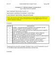
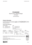
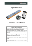
1
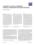
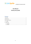
SH-1 Embedded Workhorse Breakout-Board
User Manual
Version 1.0
January 1999
Xtreme Ideas Technology Development
Xtreme Ideas Technology Development
NOTICE
This document is subject to change without notice.
Neither Xtreme Ideas Technology Development nor the inventor, Andrew Huang, will be
held responsible for any damage to the user or user’s assets that may result from
accidents or any other reasons during operation of the user’s unit according to this
document.
No license is granted by implication or otherwise under any patents or other rights of any
third party or Xtreme Ideas Technology Devolpment, or Andrew Huang.
This product is not authorized for use in medical applications, including but not limited to
life support systems.
© 1998 Andrew Huang, All Rights Reserved
The Xtreme Ideas logo is a trademark of Xtreme Ideas Technology Development
SH-1 Embedded Workhorse Breakout Board User's Manual
2
Xtreme Ideas Technology Development
1 Feature Summary
•
•
•
all signals on SH1WH expansion bus broken out into 0.1" spaced dual-row header
pads
Vutil regulator (+5V linear regulator)
Optional FPGA for 32 lines of enhanced digital I/O
SH1WH
Expansion Bus
User Voltage
(6.8-13V)
Linear
Regulator
Headers Grouped
by Function
5V
FPGA
Enhanced Digital I/O
Expansion Header
Figure 1: Block Diagram of SH1WH Breakout-Board
SH-1 Embedded Workhorse Breakout Board User's Manual
3
Xtreme Ideas Technology Development
Table of Contents
1
FEATURE SUMMARY
3
DESCRIPTIVE SPECIFICATIONS
5
1.1
5
Power Supply
1.2
Jumper Locations and Pinouts
1.2.1
JP1 – Analog Header
1.2.2
JP2 – Power Management and SH-1 Direct I/O
1.2.3
JP3 – A/D Trigger Header
1.2.4
JP5 – Motor Control Header
1.2.5
JP6 – Processor Expansion Header
1.2.6
JP7 – Vutil Breakout Header
1.2.7
JP8 – Vbatt Breakout Header
1.2.8
JP9 – Enhanced Digital I/O Header
1.2.9
Vbatt Terminal Block
5
5
5
6
6
6
7
7
8
8
1.3
Signal Descriptions
1.3.1
Direct Processor Bus Signals
1.3.2
Digital I/O
1.3.3
Analog Signals
1.3.4
Power Control
1.3.5
Power
1.3.6
Miscellaneous
9
9
10
10
11
11
11
2
LOCATION OF HEADERS
11
3
UCF-FORMAT PIN LOCATIONS FOR FPGA
12
SH-1 Embedded Workhorse Breakout Board User's Manual
4
Xtreme Ideas Technology Development
Descriptive Specifications
1.1 Power Supply
The SH1WH-BB1 has a screw-type terminal block for connecting power to both the
breakout board and other boards in the expansion connector stack. The voltage applied to
the terminal block is distributed to other boards in two forms; the raw voltage is applied
to other boards as Vbatt, and a regulated +5V voltage is provided as Vutil. The voltage
input is restricted to a range of 6.8V to 13V due to the +5V linear regulator on board the
breakout board (the SH1WH alone can accept voltages as low as 3.8V by itself). The
+5V regulated output is used by the FPGA. Boards without the FPGA option that do not
use Vutil can operate at lower voltages without failure.
1.2 Jumper Locations and Pinouts
The SH1WH-BB1 has 8 headers and one terminal block total. The headers are provided
unpopulated so the user can put either male or female connectors of various lengths and
styles, depending on the user's application.
1.2.1 JP1 – Analog Header
The analog header breaks out 8 A/D channels as well as 2 D/A channels and their
reference voltages. Note that the grounds on this header are the analog grounds, and they
should not be tied to the digital grounds for best analog performance. The tie point
between analog and digital grounds is internal to the SH1WH board.
AGND 1
AN0 3
AN2 5
AN4 7
AN6 9
AGND 11
AGND 13
Aout0 15
2 AVrefI
4 AN1
6 AN3
8 AN5
10 AN7
12 AGND
14 AVrefO
16 Aout1
Figure 2: Analog header pinouts (all views from top)
1.2.2 JP2 – Power Management and SH-1 Direct I/O
The power management and SH1-1 Direct I/O header breaks out both Vbatt and Vutil
voltages, along with all the power management signals (RESET, NMI, shutdown, and
wake up). Also provided on this header are the five A-port processor direct signals; the
exact function of these signals is configurable inside the SH-1. Note that these A-port
processor direct signals are used to program the FPGA, and thus if the FPGA option is
populated, these signals become unavailable for general use.
SH-1 Embedded Workhorse Breakout Board User's Manual
5
Xtreme Ideas Technology Development
Vutil 1
PA11 3
PA13 5
PA15 7
VBatt 9
RESET 11
shutdwn 13
DGND 15
2 Vutil
4 PA12
6 PA14
8 DGND
10 VBatt
12 NMI
14 wake out
16 DGND
Figure 3: Power Mgmt. and SH-1 Direct I/O Header Pinouts
1.2.3 JP3 – A/D Trigger Header
The A/D trigger header is provided so users can connect an external A/D trigger source to
the SH1WH for precise timing of A/D sampling. Note that this header has DGND (not
AGND) as a reference, since the trigger signal is a digital signal. Also note that the A/D
trigger feature can not be used at the same time with multiplexed address/data peripherals
on the processor expansion header, as the address hold (AH) function is also multiplexed
on to this pin inside the SH-1.
AH/samp 1
2 DGND
Figure 4: A/D Trigger Header Pinouts
1.2.4 JP5 – Motor Control Header
All motor control lines are made available on this header for diagnostic purposes. This
also allows for a configuration of breakout-board plus motor driver card in case users
already have a PWM signal source that they want to connect to the motor driver card.
DGND 1
PWM0 3
EN0 5
DIR0 7
DGND 9
PWM2 11
EN2 13
DIR2 15
PWM4 17
EN4 19
2 DGND
4 PWM1
6 EN1
8 DIR1
10 DGND
12 PWM3
14 EN3
16 DIR3
18 DIR4
20 DGND
Figure 5: Motor Control Header Pinouts
1.2.5 JP6 – Processor Expansion Header
The processor expansion header allows users to connect extra memory-mapped
peripherals to the SH-1.
SH-1 Embedded Workhorse Breakout Board User's Manual
6
Xtreme Ideas Technology Development
Vutil 1
AD0 3
AD2 5
AD3 7
AD6 9
DGND 11
A0 13
A2 15
A4 17
A6 19
DGND 21
CS6 23
RD 25
RESET 27
CLK 29
2 Vutil
4 AD1
6 AD3
8 AD5
10 AD7
12 DGND
14 A1
16 A3
18 A5
20 A7
22 AH/samp
24 CS7
26 WR
28 DGND
30 DGND
Figure 6: Processor Expansion Header Pinouts
1.2.6 JP7 – Vutil Breakout Header
The Vutil breakout header is provided so users can have a convenient source of regulated
+5V for their projects. There are a couple of NC pins so users can put in a keyed
connector to prevent users from plugging in a power connector backwards.
Vutil 1
Vutil 2
NC 3
PGND 4
NC 5
PGND 6
Figure 7: Vutil breakout header
1.2.7 JP8 – Vbatt Breakout Header
The Vbatt breakout header is provided so users can have a convenient source of
unregulated power. It also provides an alternative method to connecting up Vbatt if they
do not wish to use the terminal block.
VBatt 1
VBatt 2
NC 3
PGND 4
NC 5
PGND 6
Figure 8: Vbatt breakout header
SH-1 Embedded Workhorse Breakout Board User's Manual
7
Xtreme Ideas Technology Development
1.2.8 JP9 – Enhanced Digital I/O Header
The enhanced digital I/O header breaks out 32 signals plus ground from the FPGA. These
signals can take on a large number of functions, depending on what configuration the
FPGA has.
DGND 1
DIG0 3
DIG2 5
DIG4 7
DIG6 9
DGND 11
DIG8 13
DIG10 15
DIG12 17
DIG14 19
DGND 21
DIG16 23
DIG18 25
DIG20 27
DIG22 29
DGND 31
DIG24 33
DIG27 35
DIG28 37
DIG30 39
2 DGND
4 DIG1
6 DIG3
8 DIG5
10 DIG7
12 DGND
14 DIG9
16 DIG11
18 DIG13
20 DIG15
22 DGND
24 DIG17
26 DIG19
28 DIG21
30 DIG23
32 DGND
34 DIG25
36 DIG27
38 DIG29
40 DIG31
Figure 9: Enhanced Digital I/O Header Pinouts
1.2.9 Vbatt Terminal Block
The Vbatt terminal block provides convenient screw terminals to which users can connect
voltages from 6.8V to 13V to power the card stack.
View from side of board
+ Figure 10: Terminal Block Pinouts
SH-1 Embedded Workhorse Breakout Board User's Manual
8
Xtreme Ideas Technology Development
1.3 Signal Descriptions
1.3.1 Direct Processor Bus Signals
AD[7:0]
I/O
Multimode address and data bus. Depending on access location, this
bus may behave either as a multiplexed address/data bus or as just a
data bus. This bus may also be treated as either a simple 8-bit bus or
the lower byte of a 16-bit wide bus.
A[7:0]
O
Address bits from the processor
RD
O
Read enable from the processor, active low
WR
O
Write enable from the processor, active low
CS7
O
Chip select from the processor, active low. This CS line corresponds
to 8-bit accesses with an unmultiplexed bus mode in addresses from
0x7000000 to 0x7FFFFFF.
CS6
O
Chip select from the processor, active low. This CS line corresponds
to 8 or 16-bit wide accesses in a multiplexed address/data bus mode
in addresses from 0x6000000 to 0x6FFFFFF; if the 14th address bit is
high, then the bus behaves as if it were 16 bits wide; if it is low, then
the bus behaves as if it were 8 bits wide. It also corresponds to 16-bit
accesses in an unmultiplexed bus mode in addresses from 0xE000000
to 0xEFFFFFF.
RES
I/O
Hard reset, active low. This signal is debounced and pulled low for
250 ms on any of the following conditions: reset button depressed,
Vcc out of range (2.88V typ.), power-on reset, or watchdog timer
time-out (if enabled). A hard reset will clear processor state and is
required to wake up out of deep-sleep modes. RES is a wired-AND
signal, so users may pull RES low to force a reset condition.
CLK
O
12 MHz clock signal, synchronous to direct processor bus signals
NMI
O
Non-maskable interrupt output. This signal is triggered when the
alarm clock in the RTC times out, or when the user depresses the
NMI button.
AH/samp I/O
Software configurable pin to either address hold output or A/D
sample trigger input. Address hold is used when the expansion bus is
in multiplexed address/data mode. A/D sample trigger is optional as
the sample trigger can be set by software as well.
SH-1 Embedded Workhorse Breakout Board User's Manual
9
Xtreme Ideas Technology Development
1.3.2 Digital I/O
PA[15:11] I/O
Programmable function digital I/O ports. In addition to simple digital
I/O, PA[15:12] can also be remapped in software to function as
active-low interrupt lines or DMA handshaking lines; PA11 can be
remapped to function as a timing pattern generator output.
PWM[4:0] I/O
Pulse width modulation control output. Dedicated hardware drive
these lines with square waves of varying duty cycles; properties of the
PWM output are set by software. These signals can also be
configured to function as digital I/O, timing pattern generator outputs,
or as interval timer inputs.
EN[4:0]
O
Dedicated digital outputs. While the label may suggest that it can be
used to enable motors under PWM control, this output may be used
for any function. EN[4:0] maps to bits 4:0 of any data written to
locations ranging from 0xA000000 through 0xAFFFFFF.
DIR[4:0]
O
Dedicated digital outputs. While the label may suggest that it can be
used to set the direction of motors under PWM control, this output
may be used for any function. DIR[4:0] maps to bits 12:8 of any data
written to locations ranging from 0xA000000 through 0xAFFFFFF.
1.3.3 Analog Signals
AN[7:0]
I
Input to A/D converter. The A/D converter is a 10-bit SAR type
converter.
Aout[1:0] O
Output of D/A converters. The D/A converters have 12-bit resolution.
AVrefI
O
Reference voltage used by the A/D converter. This AGND-referenced
voltage represents the maximum voltage that the A/D converter can
sample. Excessive current draw from this output will affect A/D
converter accuracy.
AVrefO
O
Reference voltage used by the D/A converter. This AGND-referenced
voltage represents the maximum voltage output by the D/A converter.
Excessive current draw from this output will affect D/A converter
accuracy.
AGND
PWR Analog ground. This is an isolated, low-current return path for analog
signals.
SH-1 Embedded Workhorse Breakout Board User's Manual
10
Xtreme Ideas Technology Development
1.3.4 Power Control
shutdwn
I
A high input on this pin causes the switching regulator to shut down,
effectively turning the board off. This input is internally tied low with
a 10K resistor.
wakeout
O
This is an alarm clock output that functions regardless of the state of
Vcc. Its polarity and trigger time is programmable. It is internally
connected to the NMI of the processor.
1.3.5 Power
Vutil
NC
This is a utility voltage pin provided on the expansion headers for use
by expansion cards. It is not connected on the SH1WH.
DGND
PWR Digital signal ground.
PGND
PWR Power ground; high current return path for system power.
Vbatt
PWR System power. Nominally provided by a battery, but any unregulated
DC input between 3.8 and 13V is acceptable.
1.3.6 Miscellaneous
NC
NC
Internally not connected. For use by expansion cards.
2 Location of Headers
JP6
JP7
JP5
JP1
JP2
JP8
JP3
JP9
Vbatt Header
Figure 11: Location of headers and respective pin 1 locations
SH-1 Embedded Workhorse Breakout Board User's Manual
11
Xtreme Ideas Technology Development
3 UCF-Format Pin Locations for FPGA
The following listing is a Xilinx User Constraint File (.UCF) compatible mapping of pin
numbers to pin functions for the FPGA aboard the SH1WH-BB1-FPGA. This listing
assumes the user places all I/O functions into a hierarchical block with the designator
"U1". This listing is compatible with the Xilinx Foundation Series tools, version 1.5. An
archived sample project with this information in a .UCF file for the Xilinx tools is
available on the web at http://www.ai.mit.edu/people/bunnie/sh1wh/fpga.zip.
NET U1/PCLK
LOC = P2;
NET U1/DIG0
LOC = P3;
NET U1/DIG1
LOC = P7;
NET U1/DIG2
LOC = P8;
NET U1/DIG3
LOC = P9;
NET U1/DIG4
LOC = P10;
NET U1/DIG5
LOC = P13;
NET U1/DIG6
LOC = P14;
NET U1/DIG7
LOC = P15;
NET U1/DIG8
LOC = P16;
NET U1/DIG9
LOC = P17;
NET U1/DIG10
LOC = P18;
NET U1/DIG11
LOC = P19;
NET U1/DIG12
LOC = P20;
NET U1/HDC
LOC = P28;
NET U1/DIG13
LOC = P29;
NET U1/DIG14
LOC = P31;
NET U1/DIG15
LOC = P32;
NET U1/DIG16
LOC = P33;
NET U1/DIG17
LOC = P34;
NET U1/DIG18
LOC = P35;
#NET U1/P_PA14
LOC = P36;
NET U1/DIG19
LOC = P39;
NET U1/DIG20
LOC = P40;
NET U1/DIG21
LOC = P41;
NET U1/DIG22
LOC = P42;
NET U1/DIG23
LOC = P43;
NET U1/DIG24
LOC = P44;
NET U1/DIG25
LOC = P45;
NET U1/DIG26
LOC = P46;
NET U1/DIG27
LOC = P47;
#NET U1/P_PA15
LOC = P50;
#NET U1/P_PA13
LOC = P52;
NET U1/P_PA13C1
LOC = P58;
NET U1/P_PA13C2
LOC = P54;
NET U1/DIG28
LOC = P53;
NET U1/DIG29
LOC = P55;
NET U1/DIG30
LOC = P56;
NET U1/DIG31
LOC = P57;
NET U1/P_TIOCA4
LOC = P59;
NET U1/P_AD0
LOC = P60;
NET U1/P_AD1
LOC = P61;
NET U1/P_AD2
LOC = P62;
NET U1/P_AD3
LOC = P65;
NET U1/P_AD4
LOC = P66;
SH-1 Embedded Workhorse Breakout Board User's Manual
12
Xtreme Ideas Technology Development
NET U1/P_AD5
LOC = P67;
NET U1/P_AD6
LOC = P68;
NET U1/P_AD7
LOC = P69;
NET U1/P_A0
LOC = P70;
NET U1/P_A1
LOC = P71;
#NET U1/P_PA12
LOC = P72;
#NET U1/P_PA11
LOC = P74;
NET U1/P_A2
LOC = P78;
NET U1/P_A3
LOC = P80;
NET U1/P_A4
LOC = P81;
NET U1/P_A5
LOC = P82;
NET U1/P_A6
LOC = P83;
NET U1/P_A7
LOC = P84;
NET U1/P_AH_N
LOC = P85;
NET U1/P_CS6_N
LOC = P86;
NET U1/P_CS7_N
LOC = P87;
NET U1/P_RD_N
LOC = P90;
NET U1/P_WR_N
LOC = P91;
NET U1/RESET
LOC = P92;
NET U1/SHUTDOWN
LOC = P93;
NET U1/NMI
LOC = P94;
NET U1/WD_TRIG
LOC = P95;
NET U1/P_TIOCA0
LOC = P96;
NET U1/P_TIOCA1
LOC = P97;
NET U1/P_TIOCA2
LOC = P98;
NET U1/P_TIOCA3
LOC = P99;
SH-1 Embedded Workhorse Breakout Board User's Manual
13
Xtreme Ideas Technology Development
NOTES:
SH-1 Embedded Workhorse Breakout Board User's Manual
14