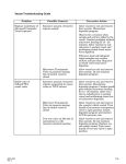
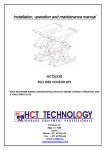
1
CAUTION
Hall sensor is very fragile; in order to make difference of good quality from bad, do not tear off the seal
of the sensor before you start to use it. You may take following steps to check in advance:
1. Joint plug of Hall sensor with apparatus.
2. Switch on the power supply, then step on adjusting and zeroing, generally you could adjust to “zero”
line, it is testified that the sensor is in good condition. If the needle could not be adjusted to zero line
or out of order, our factory is responsible of repairing. While for the sensor is device easy to break
off, so we could not take responsibility if it is broken when the seal is torn open. However, we still
repair the whole apparatus for you.
3. Tearing the seal and unscrewing metal cap, then you may operate it. Please be noticed that you
should pull out the cap with direct orientation when you unscrew and do not try to do in deviation,
avoiding the cap touching the head of sensor and break it.
4. In addition, during the process of usage, please pay special attention to the head of sensor, avoiding
any pressing, crushing, twisting, bending and clashing, etc. in order to avoid the apparatus being
destroyed and could be used, it is best to name specified personnel to use it.
1.Summary
CT5A Hall effect tesla is a kind of magnetoelectricity multi-range tesla that composes with integrated
calculating amplifier. It uses Hall effect theory and high gain, low deviation. It can once test AC
magnetic flux density fast and exactly, so can be used as a convenient and time-saved necessary
apparatus for magnetic testing personnel.
2. Characteristics of apparatus
1. The probe of the apparatus can be replaced and the apparatus is composed with host part and probe
(that is Hall sensor). The chip in probe is a gallium arsenide Hall magnet-sensitive device that
characterizes as low deviation, high linearity, and sizing 1*1. Besides this, the capability of circuit of
host part is very stable. All this successfully settled the problem that the old CT5 tesla had. Old CT5
only have one probe and its probe cannot be replaced.
2. This apparatus displays with magnetoelectricity pointer and its dial has clear reflecting mirror,
magnetic field 0~2.5T all using one scale, users could check the value of magnetic field in the testing
in a short while.
3. In addition, different magnetic wares have different sensitivity, so on the dial there has one standard
reading constant line (T) and the users could adjust according to the probe the factory originally
provided. By this way, you can precisely test out the value of magnetic field you needed.
4. This apparatus can test transverse magnetic field with clearance >1.2mm. If it equips CT5A-2 Hall
sensor, it can test axial magnetic field of trachea with diameter>ф7mm.
5. The apparatus CT5A has 18 months’ limit of guaranteeing usage. All damages which not caused by
incorrect using, we all could repair, replace or hand back.
3.Technical specifications
(1) Measuring range (mT):0~10~50~100~250~1000~2500mT
(2) Polarity of Magnetic field: N and S
(3)Accuracy: +/-2.5% for the 50 100 250 1000; +/-5% for 0-10 calculate by percentage ;
Currently it is calibrated by 1000point for 2500 scope.
(4)Operating temperature:+5 ~ +40
(5)Overall dimension of Hall sensor:3.2x1.1x35mm
(6)Using position: Horizontal position
(7)Power supply: 220V+/-10%
Overall dimension of tesla meter: 210x160x100mm
4. structure of apparatus
main parts of apparatus include: Hall sensor, compensating circuit, regulated power supply, IC
Yuxiang Magnetic Materials Ind. Co., Ltd
Add:Floor 16, Jinyuan plaza, # 57 Hubin nan Road, Xiamen, CHINA 361004
Url:Http//www.e-magnet.cn
E-mail: [email protected] or [email protected]
amplifier
Permanent
current
device
permanent current device and magnetoelectric millivotmeter, please refer to drawing 1.
Hall
sensor
Compensating
circuit
IC
amplifier
Range
selecting
Magnetoelectric
millivometer
regulated
power supply
1. Hall sensor: the apparatus has one CT5A-1 Hall sensor and can test transverse magnetic field. Also it
installs gallium arsenide Hall device and the dimension of CMOS chip is 1×1×0.2mm3, the device is
glued on the insulated scaleboard and protected by flat copper shell outside. When it installs testing
hand, the figure size of sensor is 3.2×1.1×35mm3, the device is coordinately installed the head of
copper tube. (Ref. to drawing 2)
The user could note to add CT5A-2 sensor when place the product if he needs test axial magnetic
field of trachea (that is magnetic field which parallel with the rod of sensor). The figure size of
CT5A-2 sensor <ф6.5mm, length of rod 400mm.
2. Compensating circuit: for technical reason, when match electric current, the sensor originally has no
output if it is not put into magnetic field. But because the voltage of two sides of device isn’t at same
surface and already has output, its range changing according to different temperature. So it must
have one compensating circuit. This apparatus take bridge circuit to compensate and use zeroing
knob to adjust before beginning to test. Through this way, the output on the dial is zero in the normal
state.
Yuxiang Magnetic Materials Ind. Co., Ltd
Add:Floor 16, Jinyuan plaza, # 57 Hubin nan Road, Xiamen, CHINA 361004
Url:Http//www.e-magnet.cn
E-mail: [email protected] or [email protected]
3. Regulated power supply: there are two suits of reliable three-ended integrated regulators under the
shell of apparatus.
(1) 9Vfor permanent current and
(2) (2)12V for FC72 amplifier.
4. AC amplifier: in order to expand its range, the apparatus uses FC72C, high linearity, low deviation
CI calculating amplifier to advance its sensitivity, shorten its size and predigest its craftwork. The
apparatus has zeroing device to adjust the zero line of amplifier.
5. Permanent current device: during the process of testing, the working current of Hall sensor should
not be changed. Especially when testing magnetic field, the magnetic blocking effect is apparent and
so that will effect variation of working current. This apparatus uses Foo7C linearity IC, guaranteeing
the working current is unchanged when testing. At the same time, in order to assort with
ununiformity of sensitivity of device and temperature effect, the apparatus installs one adjustable
calibration device as compensation.
6. magnetoelectric millivotmeter: the appartatus uses high sensitive testing device and parallel in series
resistance to make up a wide-range millivotmeter. Also it adjusts limit of each range by change the
resistance of connection in series. In order to protect the testing device during the process of
transportation, the apparatus has “off” button to make the device in short circuit.
5.Testing theory
1. Hall effect means that electrify on the two traverse sides (1.3) of a piece of thin semiconductor slice,
at this time, electrons in semiconductor move with direction reversely from IH. When putting into
Yuxiang Magnetic Materials Ind. Co., Ltd
Add:Floor 16, Jinyuan plaza, # 57 Hubin nan Road, Xiamen, CHINA 361004
Url:Http//www.e-magnet.cn
E-mail: [email protected] or [email protected]
the magnetic field B that is vertical with surface of semiconductor, electrons will change their way
(so called Laurence strength) because of the effect of strength of magnetic field (BH) and produce
electron accumulation on one traverse side of the slice, then resulting in building electric field
between two sides (2.4). When magnetic force FB equals to electric force FE, the accumulation of
electron reaches to homeostasis and then produces a stable Hall electric potential VH. We call this
phenomenon as Hall effect.
Initial connection:
VH=KH IH COS0
IH------working current
B-------magnetic flux density
KH-----sensitivity of device (relevant to shape coefficient fBL, thickness d and Hall constant RH)
VH------Hall electric potential
O------stands the angle between two lines of direction of magnetic field and plane of semiconductor.
From above we can understand that, when the size of material of semiconductor is decided, working
current is given, at this time, the Hall electric potential VH will be in direct ratio to tested magnetic field
B. if the position of Hall device and magnetic field is fixed up, when angle 0=0(that is the outputs comes
to max.), VH is in direct ratio to B.
2. This apparatus is produced according to Hall effect theory mentioned above. In order to ensure to
keep working current stable, the apparatus uses F007 as permanent current circuit to provide power
to device IH and takes FC72C IC AC amplifier to expand range, helping reading-enlarger of high
sensitive millivotmeter to output VH and so that people could read the magnetic flux density B
directly.
3. Attention:
The reading number of this apparatus indicates the number of magnetic flux density of testing point,
which is different from B in practical usage and parameter of material Br.
6.Operating instructions:
1.Caution:
(1) Hall sensor in the probe is fragile. Care should be taken to protect the Hall element from
excessive stress due to shock, pressure, bending and bump.
(2) Tesla meter should be kept and used by assigned person, so as to minimize the possibility of
damage.
(3) User manual should be read carefully before operation.
(4) Before operation, please check if there’s calibration constant marked on the probe.
(5) Before operation, please check if the copper sleeve on the hall sensor is tight enough, if not,
Yuxiang Magnetic Materials Ind. Co., Ltd
Add:Floor 16, Jinyuan plaza, # 57 Hubin nan Road, Xiamen, CHINA 361004
Url:Http//www.e-magnet.cn
E-mail: [email protected] or [email protected]
please fasten it.
(6) Hall sensor should not be used in environment with strong sunlight, temperature higher than 60
and corrosive gas.
(7) Tesla meter should not be stored near strong magnetic field, and should be keep at least 1M afar
from the same.
2. Operating instructions
(1) Zeroing—Turn the measuring knob to “OFF”(关) first, adjust the mechanical zero setter(0) in
the instrument's center, to make the pointer locate on zero line(0).
Caution: --This process should be adjusted carefully before connecting power supply, so as to
ensure the accuracy rate.
(2) Connecting power supply.
a. Connecting power supply outlet and Hall Sensor with Tesla meter
b. Press down the power supply indicator “.” On the left side.
c. Connecting power supply (220V+/-10%, 50Hz)
Calibration line adjust—When the measuring knob indicates “Calibration”(校准), the pointer should
locate near the “”calibration constant"(which could be found on the probe). Warm-up for 30 minutes,
then adjust the “calibration” hole(校准), make the pointer locate exactly on “calibration constant”.
Caution:
a. This equipment adopts constant current circuit, and usually the current changes seldom. Adjust is
only needed when ambient temperature changes considerably. If the current fluctuates too greatly,
please check if the constant current apparatus is out of order.
(4)Zeroing of amplifier—adjust the measuring knob to indicate “0”, adjust mechanical zero setter (0)
in the instrument’s center, and make the pointer to locate exactly on zero line (0).
(5)“Zeroing” knob(调零)
a. When use 50~2500mT measuring range, adjust the measuring knob to indicate “50”, then adjust
the “zeroing” knob(调零), to make the pointer to locate exactly on zero line (0), then adjust the
measuring knob to the range which will be measured, after repeating the zeroing process,
measuring work could start.
b. When use 10mT, adjust the measuring knob to indicate “10”, then adjust the “zeroing” knob(调
零) to make the pointer to locate exactly on zero line (0).
Caution:
c. When in use (especially measuring 10~100mT), if the probe is pressed, distorted or temperature
on the magnets to be measured changes, the zeroing process should be performed to eliminate
errors.
d. Due to the high sensitivity of 10mT measuring range, tester should check frequently if the zero
line”0” changes? If so, zeroing process should be performed before measuring.
e. When zeroing, the hall sensor should not be place near magnetic field.
(3) Measuring:
a. Adjust the measuring knob to the measuring range desired.
b. Remove the metal and plastic protecting cap on the hall sensor.
c. Put the top of hall sensor into the magnetic field to be measured,
d. Slowly moving the hall sensor, locate the max. Value (the angle between magnetic field
measured and hall sensor should be 90degree) measured on the magnets, which is the reading of
magnetic field measured.
e. When measuring is finished, adjust the measuring knob to “OFF”(关), the turn off the power
supply, disconnect the hall sensor.
Caution:
a. Before measuring, please check and ensure the above 1~5 processes are correct.
b. When measuring, hall sensor’s plane should be perpendicular to the magnetic field to be
Yuxiang Magnetic Materials Ind. Co., Ltd
Add:Floor 16, Jinyuan plaza, # 57 Hubin nan Road, Xiamen, CHINA 361004
Url:Http//www.e-magnet.cn
E-mail: [email protected] or [email protected]
measured.
c. When measuring, the hall sensor should be moved slowly and slightly, to prevent it from being
damaged.
(4) Polarity identification of magnetic field:
When measuring, when the pointer locate from “0” to max. Value measured, check the copper
tube on the hall sensor, the side with “N” on the probe is N pole, and conversely it is S pole.
7. Examine and repair for apparatus
1. Sensor:
(1) The knob indicates “50” while could not adjust to zero line, even the reading number reach the
end of scale;
(2) The knob indicates “adjusting” while could not reach to adjusting line (even only reach to
“0”scale sometimes).
Checking method: using range R 10 of multi-purpose meter to measure the resistance of (1,3) and
(2,4) of the sensor. Eligible resistance of device should be 400~600Ω, reading number should not
have great discrepancy.
(1) Four wires of sensor are broken or badly connected (this happens more easily when the copper
tube is flexible). You should check it very carefully and weld tightly so that it would be ok.
(2) Because of pressing or bending, the sensor has had leakage and resulted in making inner
resistance larger. If this happens, it can not be repaired and only take a new sensor, however,
since there exchange limit between different sensors, so it should be sent to factory with
apparatus to make repairs and supply replacements.
2. FC72 amplifier
Malfunction: the indication “0” could not be adjusted to zero line when the knob indicates “0”; this
means the amplifier is out of order.
Checking method:
(1)Take part of the apparatus and check whether the “zero to ground” on the printed circuit board is
+12V and “six to ground” is –12V.
(2)Check whether the potentiometer is broken.
(3)If two points above are in good condition, it indicates that the amplifier has been out of order or
badly connected.
3. Permanent current supply:
Malfunction:
(1) The knob indicates “adjusting” while could not adjust to adjusting line, but the checking of
sensor testified that it is in well condition.
(2) The knob could adjust to adjusting line, while the reading of the scale is not stable or changed
constantly.
Checking method:
(1) Check when put 7 feet or 4 feet of F007 to ground, the voltage should be
9V.
(2) Check when 2 feet of F007 to ground, the voltage should be about 1V and two sides of 2DW7C
voltage regulator under low part of circuit should be 6V.
8.Package content:
1.CT5A tesla meter: 1set
2.Hall sensor:
1pcs
3.Wire connecting power supply: 1pcs
4.Carton: 1pcs
5.User manual: 1 copy
6.Product’s qualification certificate: 1 copy
7.Fuse: 2pcs
Yuxiang Magnetic Materials Ind. Co., Ltd
Add:Floor 16, Jinyuan plaza, # 57 Hubin nan Road, Xiamen, CHINA 361004
Url:Http//www.e-magnet.cn
E-mail: [email protected] or [email protected]
9. Theory circuit diagram
Xiamen Yuxiang Magnetic Materials Ind. Co., Ltd
Add: 16Fl,Jinyuan Building, No 57,Hubin South Road,Xiamen,China
Url:Http://www.magnets.com.cn Email: [email protected]