1
GA-K8NS
AMD Socket 754 Processor Motherboard
User's Manual
Rev. 1001
12ME-K8NS-1001
Copyright
© 2004 GIGABYTE TECHNOLOGY CO., LTD
Copyright by GIGA-BYTE TECHNOLOGY CO., LTD. ("GBT"). No part of this manual may be reproduced or transmitted in any from
without the expressed, written permission of GBT.
Trademarks
Third-party brands and names are the property of their respective owners.
Notice
Please do not remove any labels on motherboard, this may void the warranty of this motherboard.
Due to rapid change in technology, some of the specifications might be out of date before publication of this booklet.
The author assumes no responsibility for any errors or omissions that may appear in this document nor does the author make a
commitment to update the information contained herein.
Mother Board
GA-K8NS
Apr. 2, 2004
Motherboard
GA-K8NS
Apr. 2, 2004
English
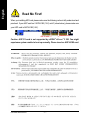
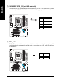
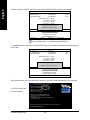
Read Me First!
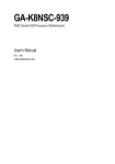
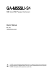
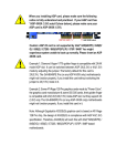
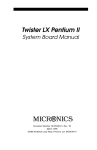
When you installing AGP card, please make sure the following notice is fully understood and
practiced. If your AGP card has "AGP 4X/8X (1.5V) notch" (show below), please make sure
your AGP card is AGP 4X/8X(1.5V).
AGP 4X/8X notch
Caution: AGP 2X card is not supported by nVIDIA nForce 3 250. You might
experience system unable to boot up normally. Please insert an AGP 4X/8X card.
®
GA-K8NS Motherboard
-4-
TM
Computer motherboards and expansion cards contain very delicate Integrated Circuit (IC) chips. To
protect them against damage from static electricity, you should follow some precautions whenever
you work on your computer.
1. Unplug your computer when working on the inside.
2. Use a grounded wrist strap before handling computer components. If you do not have
one, touch both of your hands to a safely grounded object or to a metal object, such as
the power supply case.
3. Hold components by the edges and try not touch the IC chips, leads or connectors, or
other components.
4. Place components on a grounded antistatic pad or on the bag that came with the
components whenever the components are separated from the system.
5. Ensure that the ATX power supply is switched off before you plug in or remove the ATX
power connector on the motherboard.
Installing the motherboard to the chassis…
If the motherboard has mounting holes, but they don't line up with the holes on the base and there
are no slots to attach the spacers, do not become alarmed you can still attach the spacers to the
mounting holes. Just cut the bottom portion of the spacers (the spacer may be a little hard to cut off,
so be careful of your hands). In this way you can still attach the motherboard to the base without
worrying about short circuits. Sometimes you may need to use the plastic springs to isolate the
screw from the motherboard PCB surface, because the circuit wire may be near by the hole. Be
careful, don't let the screw contact any printed circuit write or parts on the PCB that are near the
fixing hole, otherwise it may damage the board or cause board malfunctioning.
The manufacturer assumes no liability for any damage, caused directly or indirectly, by improper
installation of any comfortable performing the installation, consult a qualified computer technician.
Damage to system components, and injury to yourself may result if power is applied during
installation.
5
Read Me First
English
Preparing Your Computer
English
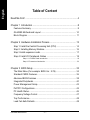
Table of Content
Read Me First! ........................................................................................ 4
Chapter 1 Introduction ............................................................................ 8
Features Summary ...................................................................................... 8
GA-K8NS Motherboard Layout .................................................................. 10
Block Diagram ........................................................................................... 11
Chapter 2 Hardware Installation Process ............................................. 13
Step 1: Install the Central Processing Unit (CPU) ..................................... 14
Step 2: Installing Memory Modules ........................................................... 16
Step 3 Install expansion cards .................................................................. 17
Step 4: Install I/O Peripherals Cables ....................................................... 18
Step 4-1: I/O Back Panel Introduction ............................................................................ 18
Step 4-2: Connectors Introduction .................................................................................. 20
Chapter 3 BIOS Setup ......................................................................... 33
The Main Menu (For example: BIOS Ver. : E19) ...................................... 34
Standard CMOS Features ......................................................................... 36
Advanced BIOS Features .......................................................................... 38
Integrated Peripherals ............................................................................... 40
Power Management Setup ....................................................................... 43
PnP/PCI Configurations ............................................................................. 45
PC Health Status ........................................................................................ 46
Frequency/Voltage Control ........................................................................ 47
Top Performance ...................................................................................... 48
Load Fail-Safe Defaults ............................................................................. 48
GA-K8NS Motherboard
-6-
Set Supervisor/User Password .................................................................. 49
Exit Without Saving .................................................................................... 50
Save & Exit Setup ....................................................................................... 50
Chapter 4 Technical Reference ........................................................... 53
@BIOS™ Introduction ................................................................................. 53
Flash BIOS Method Introduction ............................................................... 54
2- / 4- / 6- / 8- Channel Audio Function Introduction ................................. 65
Jack-Sensing and UAJ Introduction .......................................................... 71
Xpress Recovery Introduction ................................................................... 73
Serial ATA BIOS Setting Utility Introduction ............................................... 76
Chapter 5 Appendix ............................................................................. 83
-7-
Table of Content
English
Load Optimized Defaults ........................................................................... 49
English
Chapter 1 Introduction
Features Summary
CPU
On-Board IDE
y
y
y
y
y
y
y
y
y
y
On-Board Floppy
y
Chipset
Memory
Slots
On-Board SATA
On-Board Peripherals
y
y
y
y
y
y
y
y
On-Board LAN
y
y
On-Board Sound
y
y
y
y
y
y
y
On-Board SATA RAID y
(SATA0_SB, SATA1_SB) y
y
y
y
Socket 754 for AMD Althlon™ 64 processor (K8)
1600MHz system bus
Supports core frequencies in excess of 1.6GHz(2800+) and faster
nVIDIA® nForce3 250
3 184-pin DDR DIMM sockets, support up to 3GB DRAM (Max.)
Supports DDR400/333/266 DIMM
Supports DDR DIMM
1 AGP slot supports 8X/4X(1.5V) mode
5 PCI slots
2 IDE controllers provide IDE HDD/CD-ROM (IDE1, IDE2) with
PIO, Bus Master(DMA33/ATA66/ATA100/ATA133) operation modes
1 Floppy port supports 2 FDD with 360K, 720K,1.2M, 1.44M and
2.88M bytes
2 Serial ATA connectors
1 Parallel port supports Normal/EPP/ECP mode
2 Serial ports (COMA & COMB)
8 x USB 2.0/1.1 ports (4 x rear, 4 x front by cable)
1 Front audio connector
1 IrDA connector for IR/CIR
1 PS/2 keyboard
1 PS/2 mouse
Built-in ICS 1883 (10/100 Mbit)
1 RJ45 port
ALC850 CODEC (UAJ)
Supports Jack Sensing function
Supports 2-/4-/6-/8-channel
Line Out / Line In / Mic In
Surround Back Speaker (by optional Surround-Kit)
SPDIF In / Out
CD In / Game connector
Built-in nVIDIA® nForce3 250
Supports disk striping (RAID 0) or disk mirroring (RAID 1)
Supports JBOD function
Supports UDMA up to 150 MB/sec
Up to 2 SATA devices
TM
TM
to be continued...
GA-K8NS Motherboard
-8-
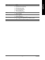
BIOS
Additional Features
Overclocking
Form Factor
y
y
y
y
y
y
y
y
y
y
y
y
y
y
IT8712
CPU/System fan revolution detect
CPU/System fan fail warning
CPU temperature detect
CPU warning temperature
System voltage detect
Thermal shutdown function
Licensed AWARD BIOS
Supports Q-Flash
Supports @BIOS
Supports EasyTune
Over clock (CPU/AGP) by BIOS
Over voltage (CPU/AGP/VCC12_HT/DDR) by BIOS
ATX size form factor, 30.5cm x 23.0cm
-9-
English
I/O Control
Hardware Monitor
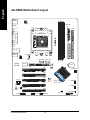
Introduction
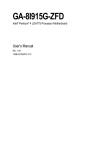
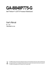
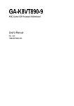
KB_MS
ATX_12V
RAM_LED
R_USB
COMB
FDD
ATX
LAN1
COMA
GA-K8NS
LPT
SOCKET 754
2X_DET
SATA0_SB
SATA1_SB
DDR3
F_AUDIO
DDR1
CPU_FAN
AUDIO
DDR2
USB
English
GA-K8NS Motherboard Layout
IDE2 IDE1
IT8712
ICS 1883
BAT
AGP
PCI1
SYS_FAN
PCI2
PCI3
CD_IN
BIOS
PCI4
nVIDIA®
nForce ™ 3 250
SUR_CEN
F_USB2
F_USB1
SPDIF_IO
PCI5
CODEC
GAME
GA-K8NS Motherboard
IR_CIR
INFO_LINK
- 10 -
PWR_LED
CLR_CMOS
F_PANEL
English
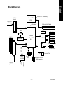
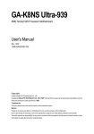
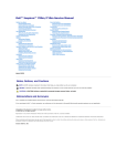
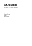
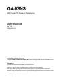
Block Diagram
AMD K8
Socket 754
AGP Slot
4X/8X
CPUCLK+/- (200MHz)
CPU
AGPCLK
(66MHz)
System Bus
1600MHz
DDR400/333 DIMM
DDR RAM
LAN
BIOS
RJ45
5 PCI
nVIDIA
nForce 3
250
TM
ICS 1883
Game Port
LPC BUS
Floppy
IT8712
24 MHz
33 MHz
AC97 Link
IR/CIR
LPT Port
PS/2 KB/Mouse
2 COM Ports
2 Serial ATA
8 USB
Ports
ATA33/66/100/133
IDE Channels
LINE-OUT
PCICLK
(33MHz)
MIC
LINE-IN
AC97
CODEC
- 11 -
Introduction
English
GA-K8NS Motherboard
- 12 -
English
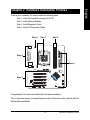
Chapter 2 Hardware Installation Process
To set up your computer, you must complete the following steps:
Step 1 - Install the Central Processing Unit (CPU)
Step 2 - Install Memory Modules
Step 3 - Install Expansion Cards
Step 4 - Install I/O Peripherals Cables
Step 4
Step 1
Step 2
Step 4
Step 4
Step 3
Congratulations! You have accomplished the hardware installation!
Turn on the power supply or connect the power cable to the power outlet. Continue with the
BIOS/software installation.
- 13 -
Hardware Installation Process
English
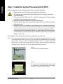
Step 1: Install the Central Processing Unit (CPU)
Before installing the processor and cooling fan, adhere to the following warning:
1. Please make sure the CPU type is supported by the motherboard.
2. The processor will overheat without the heatsink and/or fan, resulting in permanent
irreparable damage.
3. If you do not match the CPU socket Pin 1 and CPU cut edge well, it will cause improper
installation. Please change the insert orientation.
4. Apply thermal grease between the processor and cooling fan.
5. Never run the processor without the heatsink properly and firmly attached. Permanent
damage will result.
6. Please set the CPU host frequency in accordance with your processor's specifications.
We don't recommend you to set the system bus frequency over the CPU's specification
because these specific bus frequencies are not the standard specifications for CPU,
chipset and most of the peripherals. Whether your system can run under these specific
bus frequencies properly will depend on your hardware configurations, including CPU,
Memory, Cards…etc.
The installation of the processor and cooling fan is performed in four main steps:
Step1-1. First, check the processor pins to see that none are bent. Move the socket lever to the
unlocked position as shown in Figure 1.(90 o to the plane of the motherboard) prior to inserting
the processor. The pin 1 location is designated on the processor by a copper triangle that
matches up to a triangle on the socket as shown in Figure 2. Align the processor to the socket
and gently lower it into place. Do not force the processor into the socket.
Socket Lever
Figure 1.
Pull the rod to the 90-degree directly.
Figure 2.
Pin 1 location on the Socket and Processor. Move
the socket lever to the locked position while holding
pressure on the center of the processor.
GA-K8NS Motherboard
- 14 -
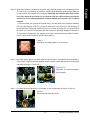
Figure 3.
Application of thermal grease to the processor.
Step 1-3.Once the thermal grease has been applied to the processor, the heatsink can be attached to
the processor. Align the heatsink assembly with the support frame mating with the backer plate
standoffs as shown in Figure 4 & 5.
Figure 4 & 5.
Alignment of heatsink assembly
with standoffs.
Step 1-4. Connect the fan power wires to the header on the motherboard as shown in Figure 6.
Figure 6.
Connecting the fan power wires.
- 15 -
Hardware Installation Process
English
Step1-2. When the processor is installed in the socket, apply thermal grease to the processor(as shown
in Figure 3) prior to installing the heatsink. Phase change materials develop strong adhesive
forces between the heatsink and processor. Removing the heatsink under such conditions can cause the processor to be removed from the socket without moving the
socket lever to the unlocked position and then damage the processor pins or socket
contacts.
** We recommend you to apply the thermal tape to provide better heat conduction between
your CPU and heatsink. (The CPU cooling fan might stick to the CPU due to the hardening of
the thermal paste. During this condition if you try to remove the cooling fan, you might pull the
processor out of the CPU socket alone with the cooling fan, and might damage the processor.
To avoid this from happening, we suggest you to either use thermal tape instead of thermal
paste, or remove the cooling fan with extreme caution.)
English
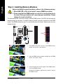
Step 2: Installing Memory Modules
Before installing the memory modules, adhere to the following warning:
1. When RAM LED is ON, do not install / remove DIMM from socket.
2. Please note that the DIMM module can only fit in one direction due to
the notch. Wrong orientation will cause improper installation. Please
change the insert orientation.
The motherboard has 3 dual inline memory module (DIMM) sockets. The BIOS will automatically
detects memory type and size. To install the memory module, just push it vertically into the DIMM
socket. The DIMM module can only fit in one direction due to the notch. Memory size can vary
between sockets.
Notch
DDR
1. The DIMM socket has a notch, so the DIMM memory
module can only fit in one direction.
2. Insert the DIMM memory module vertically into the DIMM
socket. Then push it down.
3. Close the plastic clip at both edges of the DIMM sockets
to lock the DIMM module.
Reverse the installation steps when you wish to remove
the DIMM module.
GA-K8NS Motherboard
- 16 -
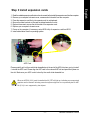
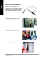
1. Read the related expansion card's instruction document before install the expansion card into the computer.
2. Remove your computer's chassis cover, screws and slot bracket from the computer.
3. Press the expansion card firmly into expansion slot in motherboard.
4. Be sure the metal contacts on the card are indeed seated in the slot.
5. Replace the screw to secure the slot bracket of the expansion card.
6. Replace your computer's chassis cover.
7. Power on the computer, if necessary, setup BIOS utility of expansion card from BIOS.
8. Install related driver from the operating system.
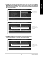
AGP Card
Please carefully pull out the small white-drawable bar at the end of the AGP slot when you try to install
/ uninstall the AGP card. Please align the AGP card to the onboard AGP slot and press firmly down on
the slot. Make sure your AGP card is locked by the small white-drawable bar.
When an AGP 2X (3.3V) card is installed the 2X_DET will light up, indicating a non-supported
graphics card is inserted. Informing users that system might not boot up normally due to AGP
2X (3.3V) is not supported by the chipset.
- 17 -
Hardware Installation Process
English
Step 3 Install expansion cards
English
Step 4: Install I/O Peripherals Cables
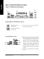
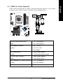
Step 4-1: I/O Back Panel Introduction
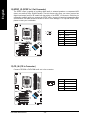
PS/2 Keyboard and PS/2 Mouse Connector
PS/2 Mouse Connector
(6 pin Female)
This connector supports standard PS/2
keyboard and PS/2 mouse.
PS/2 Keyboard Connector
(6 pin Female)
/
USB/LAN Connector
Before you connect your device(s) into USB
connector(s), please make sure your device(s)
such as USB keyboard, mouse, scanner, zip,
speaker...etc. Have a standard USB interface.
Also make sure your OS supports USB
controller. If your OS does not support USB
controller, please contact OS vendor for
possible patch or driver upgrade. For more
information please contact your OS or device(s)
vendors.
LAN
USB 0
USB 2
USB 1
USB 3
LAN connector is fast Ethernet with 10/100Mbps
speed.
GA-K8NS Motherboard
- 18 -
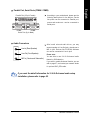
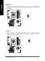
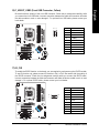
Parallel Port (25 pin Female)
According to your motherboard, please see the
following descriptions for the devices. Device
like printer can be connected to Parallel port;
mouse and modem etc. can be connected to
Serial ports.
COMA
COMB
Serial Port (9 pin Male)
Audio Connectors
After install onboard audio driver, you may
connect speaker to Line Out jack, microphone to
Line In (Rear Speaker)
Line Out (Front Speaker)
MIC In (Center and Subwoofer)
MIC In jack. Devices like CD-ROM, walkman
etc. can be connected to Line-In jack.
Please note:
You are able to use 2-/4-/6-/8-channel audio
feature by S/W selection.
If you want to enable 8-channel function you can
refer to page 27, and contact your nearest dealer
for optional SUR_CEN cable.
If you want the detail information for 2-/4-/6-/8-channel audio setup
installation, please refer to page 65.
- 19 -
Hardware Installation Process
English
Parallel Port, Serial Ports (COMA / COMB)
English
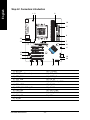
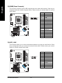
Step 4-2: Connectors Introduction
1 3
2
10
5
6
12
7
11
21
4
15
13
16
20
14
18
17
19
8
9
1) ATX_12V
2) ATX (Power Connector)
3) CPU_FAN
12) F_AUDIO
13) SUR_CEN
14) SPDIF_IO
4)
5)
6)
7)
SYS_FAN
FDD
IDE1 / IDE2
SATA0_SB / SATA1_SB
15)
16)
17)
18)
PWR_LED
F_PANEL
RAM_LED
2X_DET
19) INFO_LINK
20) CLR_CMOS
21) BAT
8)
9)
10)
11)
GA-K8NS Motherboard
- 20 -
CD_IN
F_USB1 / F_USB2
IR_CIR
GAME
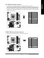
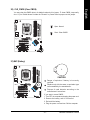
This connector (ATX_12V) supplies the CPU operation voltage(Vcore). If this "ATX_12V connector"
is not connected, system cannot boot.
Pin No.
4
2
3
1
Definition
1
GND
2
GND
3
4
+12V
+12V
2) ATX (ATX Power)
AC power cord should only be connected to your power supply unit after ATX power cable and
other related devices are firmly connected to the motherboard.
Pin No.
11
20
- 21 -
1
10
Definition
1
3.3V
2
3
3.3V
GND
4
VCC
5
GND
6
VCC
7
GND
8
9
Power Good
10
+12V
5V SB (stand by +5V)
11
3.3V
12
-12V
13
GND
14
15
PS_ON(soft on/off)
GND
16
GND
17
GND
18
-5V
19
VCC
20
VCC
Hardware Installation Process
English
1) ATX_12V (+12V Power Connector)
English
3) CPU_FAN (CPU Fan Connector)
A proper installation of the CPU cooler is essential to prevent the CPU from running under abnormal
condition or damaged by overheating. The CPU fan connector supports Max. current up to
600 mA.
1
Pin No.
Definition
1
GND
2
3
+12V
Sense
4) SYS_FAN (System Fan Connector)
This connector allows you to link with the cooling fan on the system case to lower the system
temperature.
Pin No.
1
GA-K8NS Motherboard
- 22 -
Definition
1
GND
2
+12V
3
Sense
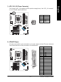
Please connect the floppy drive ribbon cables to FDD. It supports 360K, 1.2M, 720K, 1.44M and
2.88M bytes floppy disk types.
The red stripe of the ribbon cable must be the same side with the Pin1.
34
33
2
1
6) IDE1 / IDE2 (IDE1 / IDE2 Connector)
Please connect first hard disk to IDE1 and connect CD-ROM to IDE2.
The red stripe of the ribbon cable must be the same side with the Pin1.
40
39
2
1
IDE2
- 23 -
IDE1
Hardware Installation Process
English
5) FDD (Floppy Connector)
English
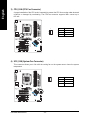
7) SATA0_SB / SATA1_SB (Serial ATA Connector)
You can connect the Serial ATA device to this connector. If you wish to use RAID function, please
use it in unity with BIOS and install the correct driver to have proper operation.
Pin No.
1
7
Definition
1
2
GND
TXP
3
TXN
4
GND
5
6
RXN
RXP
7
GND
8) PWR_LED
PWR_LED is connect with the system power indicator to indicate whether the system is on/off.
It will blink when the system enters suspend mode. If you use dual color LED, power LED will turn
to another color.
1
GA-K8NS Motherboard
- 24 -
Pin No.
Definition
1
2
MPD+
MPD-
3
MPD-
Please connect the power LED, PC speaker, reset switch and power switch etc. of your chassis
front panel to the F_PANEL connector according to the pin assignment below.
Speaker Connector
Message LED/
Power/
Sleep LED
2
1
1
SPEAK-
SPEAK+
MSG+
MSGPW+
PW-
Soft Power
Connector
20
19
1
1
1
RES+
NC
HD+
RES-
HD-
1
Reset Switch
IDE Hard Disk Active LED
HD (IDE Hard Disk Active LED)
Pin 1: LED anode(+)
(Blue)
Pin 2: LED cathode(-)
SPK (Speaker Connector)
Pin 1: VCC(+)
(Amber)
Pin 2- Pin 3: NC
Pin 4: Data(-)
RES (Reset Switch)
Open: Normal Operation
(Green)
Close: Reset Hardware System
PW (Soft Power Connector)
Open: Normal Operation
(Red)
Close: Power On/Off
MSG (Message LED / Power/ Sleep LED)
Pin 1: LED anode(+)
(Yellow)
Pin 2: LED cathode(-)
NC (Purple)
NC
- 25 -
Hardware Installation Process
English
9) F_PANEL (2 x 10 pins Connector)
_
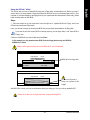
Do not remove memory modules while RAM_LED is on. It might cause short or other unexpected
damages due to the stand by voltage. Remove memory modules only when AC power cord is
disconnected.
+
English
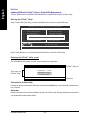
10) RAM_LED
11) 2X_DET
When an AGP 2X (3.3V) card is installed the 2X_DET will light up, indicating a non-supported
graphics card is inserted. Informing users that system might not boot up normally due to AGP 2X
(3.3V) is not supported by the chipset.
+
_
GA-K8NS Motherboard
- 26 -
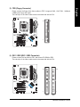
If you want to use Front Audio connector, you must remove 5-6, 9-10 Jumper.
In order to utilize the front audio header, your chassis must have front audio connector. Also please
make sure the pin assigment on the cable is the same as the pin assigment on the MB header. To
find out if the chassis you are buying support front audio connector, please contact your dealer.
Please note, you can have the alternative of using front audio connector or of using rear audio
connector to play sound.
Pin No.
1
10 9
2 1
Definition
MIC
2
GND
3
REF
4
5
Power
Front Audio (R)
6
Rear Audio (R)
7
Reserved
8
9
No Pin
Front Audio (L)
10
Rear Audio (L)
13) SUR_CEN (Surround Center Connector)
Please contact your nearest dealer for optional SUR_CEN cable.
Pin No.
2
1
- 27 -
8
7
Definition
1
SUR OUTL
2
3
SUR OUTR
GND
4
No Pin
5
CENTER_OUT
6
7
BASS_OUT
AUX_L
8
AUX_R
Hardware Installation Process
English
12) F_AUDIO (Front Audio Connector)
English
14) SPDIF_IO (SPDIF In / Out Connector)
The SPDIF output is capable of providing digital audio to external speakers or compressed AC3
data to an external Dolby Digital Decoder. Use this feature only when your stereo system has
digital input/output function. Be careful with the polarity of the SPDIF_IO connector. Check the pin
assignment carefully while you connect the SPDIF cable, incorrect connection between the cable
and connector will make the device unable to work or even damage it. For optional SPDIF cable,
please contact your local dealer.
2
1
6
5
Pin No.
Definition
1
VCC
2
3
No Pin
SPDIF
4
SPDIFI
5
GND
6
GND
15) CD_IN (CD In Connector)
Connect CD-ROM or DVD-ROM audio out to the connector.
Pin No.
1
GA-K8NS Motherboard
- 28 -
Definition
1
2
CD-L
GND
3
GND
4
CD-R
Be careful with the polarity of the front USB connector. Check the pin assignment carefully while
you connect the front USB cable, incorrect connection between the cable and connector will make
the device unable to work or even damage it. For optional front USB cable, please contact your
local dealer.
10
2
9
1
Pin No.
Definition
1
Power
2
Power
3
4
USB DxUSB Dy-
5
USB Dx+
6
USB Dy+
7
8
GND
GND
9
No Pin
10
NC
17) IR_CIR
To enable the IR/CIR function on the board, you are required to purchase an option IR/CIR module.
To use IR function only, please connect IR module to Pin1 to Pin5. Be careful with the polarity of
the IR/CIR connector. Check the pin assignment carefully while you connect the IR/CIR cable,
incorrect connection between the cable and connector will make the device unable to work or even
damage it. For optional IR/CIR cable, please contact your local dealer.
Pin No.
6
1
- 29 -
10
5
Definition
1
VCC
2
NC
3
4
IRRX
GND
5
IRTX
6
NC
7
8
CIRRX
+5VSB
9
CIRTX
10
NC
Hardware Installation Process
English
16) F_USB1/F_USB2 (Front USB Connector, Yellow)
English
18) GAME (Game Connector)
This connector supports joystick, MIDI keyboard and other relate audio devices. Check the pin
assignment while you connect the game cables. Please contact your nearest dealer for optional
game cables.
Pin No.
2
1
16
15
Definition
1
VCC
2
GRX1_R
3
4
GND
GPSA2
5
VCC
6
GPX2_R
7
8
GPY2_R
MSI_R
9
GPSA1
10
GND
11
12
GPY1_R
VCC
13
GPSB1
14
MSO_R
15
16
GPSB2
No Pin
19) INFO_LINK
This connector allows you to connect some external devices to provide you extra function. Check
the pin assignment while you connect the external device cable. Please contact your nearest
dealer for optional external device cable.
Pin No.
1
2
1
GA-K8NS Motherboard
- 30 -
10
9
Definition
SMBCLK
2
VCC
3
SMBDATA
4
5
GPIO
GND
6
GND
7
No Pin
8
9
NC
+12V
10
+12V
You may clear the CMOS data to its default values by this jumper. To clear CMOS, temporarily
shor 1-2 pin. Default doesn't include the "Shunter" to prevent from improper use this jumper.
Open: Normal
1
Short: Clear CMOS
1
21) BAT (Battery)
+
CAUTION
Danger of explosion if battery is incorrectly
replaced.
Replace only with the same or equivalent type
recommended by the manufacturer.
Dispose of used batteries according to the
manufacturer's instructions.
If you want to erase CMOS...
1. Turn OFF the computer and unplug the power cord.
2. Remove the battery, wait for 30 second.
3. Re-install the battery.
4. Plug the power cord and turn ON the computer.
- 31 -
Hardware Installation Process
English
20) CLR_CMOS (Clear CMOS)
English
GA-K8NS Motherboard
- 32 -
BIOS Setup is an overview of the BIOS Setup Program. The program that allows users to modify the
basic system configuration. This type of information is stored in battery-backed CMOS RAM so that it
retains the Setup information when the power is turned off.
ENTERING SETUP
Powering ON the computer and pressing <Del> immediately will allow you to enter Setup. If you require
more advanced BIOS settings, please go to "Advanced BIOS" setting menu. To enter
Advanced BIOS setting menu, press "Ctrl+F1" key on the BIOS screen.
CONTROL KEYS
< >
Move to previous item
< >
Move to next item
<
Move to the item in the left hand
>
< >
Move to the item in the right hand
<Enter>
Select Item
<Esc>
Main Menu - Quit and not save changes into CMOS Status Page Setup Menu and
Option Page Setup Menu - Exit current page and return to Main Menu
<+/PgUp> Increase the numeric value or make changes
<-/PgDn>
Decrease the numeric value or make changes
<F1>
General help, only for Status Page Setup Menu and Option Page Setup Menu
<F2>
Item Help
<F3>
Reserved
<F4>
Reserved
<F5>
Restore the previous CMOS value from CMOS, only for Option Page Setup Menu
<F6>
Load the file-safe default CMOS value from BIOS default table
<F7>
Load the Optimized Defaults
<F8>
Q-Flash utility
<F9>
System Information
<F10>
Save all the CMOS changes, only for Main Menu
- 33 -
BIOS Setup
English
Chapter 3 BIOS Setup
English
Main Menu
The on-line description of the highlighted setup function is displayed at the bottom of the screen.
Status Page Setup Menu / Option Page Setup Menu
Press F1 to pop up a small help window that describes the appropriate keys to use and the possible
selections for the highlighted item. To exit the Help Window press <Esc>.
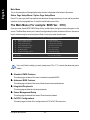
The Main Menu (For example: BIOS Ver. : E19)
Once you enter Award BIOS CMOS Setup Utility, the Main Menu (as figure below) will appear on the
screen. The Main Menu allows you to select from eight setup functions and two exit choices. Use arrow
keys to select among the items and press <Enter> to accept or enter the sub-menu.
CMOS Setup Utility-Copyright (C) 1984-2004 Award Software
`
`
`
`
`
`
`
Standard CMOS Features
Advanced BIOS Features
Integrated Peripherals
Power Management Setup
PnP/PCI Configurations
PC Health Status
Frequency/Voltage Control
Top Performance
Load Fail-Safe Defaults
Load Optimized Defaults
Set Supervisor Password
Set User Password
Save & Exit Setup
Exit Without Saving
KLJI: Select Item
F10: Save & Exit Setup
ESC: Quit
F8: Q-Flash
Time, Date, Hard Disk Type...
If you can't find the setting you want, please press "Ctrl + F1" to search the advanced option
hidden.
z Standard CMOS Features
This setup page includes all the items in standard compatible BIOS.
z Advanced BIOS Features
This setup page includes all the items of Award special enhanced features.
z Integrated Peripherals
This setup page includes all onboard peripherals.
z Power Management Setup
This setup page includes all the items of Green function features.
z PnP/PCI Configurations
This setup page includes all the configurations of PCI & PnP ISA resources.
GA-K8NS Motherboard
- 34 -
English
z PC Health Status
This setup page is the System auto detect Temperature, voltage, fan, speed.
z Frequency/Voltage Control
This setup page is control CPU’s clock and frequency ratio.
z Top Performance
If you wish to maximize the performance of your system, set "Top Performance" as "Enabled".
z Load Fail-Safe Defaults
Fail-Safe Defaults indicates the value of the system parameters which the system would be in safe
configuration.
z Load Optimized Defaults
Optimized Defaults indicates the value of the system parameters which the system would be in
best performance configuration.
z Set Supervisor Password
Change, set, or disable password. It allows you to limit access to the system and Setup, or just
to Setup.
z Set User Password
Change, set, or disable password. It allows you to limit access to the system.
z Save & Exit Setup
Save CMOS value settings to CMOS and exit setup.
z Exit Without Saving
Abandon all CMOS value changes and exit setup.
- 35 -
BIOS Setup
English
Standard CMOS Features
CMOS Setup Utility-Copyright (C) 1984-2004 Award Software
Standard CMOS Features
`
`
`
`
`
`
Date (mm:dd:yy)
Time (hh:mm:ss)
Mon, Mar 1 2004
22:31:24
IDE Channel 0 Master
IDE Channel 0 Slave
IDE Channel 1 Master
IDE Channel 1 Slave
IDE Channel 2 Master
IDE Channel 3 Master
[None]
[None]
[None]
[None]
[None]
[None]
Drive A
Drive B
Floppy 3 Mode Suport
[1.44M, 3.5"]
[None]
[Disabled]
Holt On
[All, But Keyboard]
Base Memory
Extended Memory
Total Memory
640K
127M
128M
KLJI: Move
Enter: Select
F5: Previous Values
+/-/PU/PD: Value
F6: Fail-Save Default
Item Help
Menu Level`
Change the day, month,
year
<Week>
Sun. to Sat.
<Month>
Jan. to Dec.
<Day>
1 to 31 (or maximum
allowed in the month)
<Year>
1999 to 2098
F10: Save
ESC: Exit
F7: Optimized Defaults
F1: General Help
Date
The date format
Week
Month
Day
Year
is <week>, <month>, <day>, <year>.
The week, from Sun to Sat, determined by the BIOS and is displayed only
The month, Jan. Through Dec.
The day, from 1 to 31 (or the maximum allowed in the month)
The year, from 1999 through 2098
Time
The times format in <hour> <minute> <second>. The time is calculated base on the 24-hour
military-time clock. For example, 1 p.m. is 13:00:00.
IDE Channel 0 Master, Slave / IDE Channel 1 Master, Slave / IDE Channel 2 Master / IDE
Channel 3 Master
The category identifies the types of hard disk from drive C to F that has been installed in the
computer. There are two types: auto type, and manual type. Manual type is user-definable; Auto type
which will automatically detect HDD type.
Note that the specifications of your drive must match with the drive table. The hard disk will not work
properly if you enter improper information for this category.
If you select User Type, related information will be asked to enter to the following items. Enter the
information directly from the keyboard and press <Enter>. Such information should be provided in the
documentation form your hard disk vendor or the system manufacturer.
Cylinder
Number of cylinders
Head
Number of heads
Precomp
Write precomp
Landing Zone Landing zone
Sector
Number of sectors
If a hard disk has not been installed, select NONE and press <Enter>.
GA-K8NS Motherboard
- 36 -
The category identifies the types of floppy disk drive A or drive B that has been installed in the
computer.
None
No floppy drive installed
360K, 5.25" 5.25 inch PC-type standard drive; 360K byte capacity.
1.2M, 5.25" 5.25 inch AT-type high-density drive; 1.2M byte capacity
(3.5 inch when 3 Mode is Enabled).
720K, 3.5"
3.5 inch double-sided drive; 720K byte capacity
1.44M, 3.5" 3.5 inch double-sided drive; 1.44M byte capacity.
2.88M, 3.5" 3.5 inch double-sided drive; 2.88M byte capacity.
Floppy 3 Mode Support (for Japan Area)
Disabled
Drive A
Drive B
Both
Normal Floppy Drive. (Default value)
Drive A is 3 mode Floppy Drive.
Drive B is 3 mode Floppy Drive.
Drive A & B are 3 mode Floppy Drives.
Halt on
The category determines whether the computer will stop if an error is detected during power up.
No Errors
The system boot will not stop for any error that may be detected and you
will be prompted.
All Errors
Whenever the BIOS detects a non-fatal error the system will be stopped.
All, But Keyboard The system boot will not stop for a keyboard error; it will stop for all other
errors. (Default value)
All, But Diskette
The system boot will not stop for a disk error; it will stop for all other errors.
All, But Disk/Key The system boot will not stop for a keyboard or disk error; it will stop for all
other errors.
Memory
The category is display-only which is determined by POST (Power On Self Test) of the BIOS.
Base Memory
The POST of the BIOS will determine the amount of base (or conventional) memory installed
in the system.
The value of the base memory is typically 512K for systems with 512K memory installed on
the motherboard, or 640K for systems with 640K or more memory installed on the motherboard.
Extended Memory
The BIOS determines how much extended memory is present during the POST.
This is the amount of memory located above 1 MB in the CPU's memory address map.
- 37 -
BIOS Setup
English
Drive A / Drive B
English
Advanced BIOS Features
CMOS Setup Utility-Copyright (C) 1984-2004 Award Software
Advanced BIOS Features
` Hard Disk Boot Priority
First Boot Device
Second Boot Device
Third Boot Device
Boot Up Floopy Seek
Password Check
Flexible AGP 8X
Init Display First
[Press Enter]
[Floppy]
[Hard Disk]
[CDROM]
[Disabled]
[Setup]
[Auto]
[AGP]
KLJI: Move
Enter: Select
F5: Previous Values
+/-/PU/PD: Value
F6: Fail-Save Default
Item Help
Menu Level`
F10: Save
ESC: Exit
F7: Optimized Defaults
F1: General Help
Hard Disk Boot Priority
Select boot sequence for onboard(or add-on cards) SCSI, RAID, etc.
Use < > or < > to select a device, then press<+> to move it up, or <-> to move it down the list.
Press <ESC> to exit this menu.
First / Second / Third Boot Device
Floppy
LS120
Hard Disk
CDROM
ZIP
USB-FDD
USB-ZIP
USB-CDROM
USB-HDD
LAN
Disabled
Select
Select
Select
Select
Select
Select
Select
Select
Select
Select
Select
your boot device priority by Floppy.
your boot device priority by LS120.
your boot device priority by Hard Disk.
your boot device priority by CDROM.
your boot device priority by ZIP.
your boot device priority by USB-FDD.
your boot device priority by USB-ZIP.
your boot device priority by USB-CDROM.
your boot device priority by USB-HDD.
your boot device priority by LAN.
your boot device priority by Disabled.
Boot Up Floppy Seek
During POST, BIOS will determine the floppy disk drive installed is 40 or 80 tracks. 360K type is
40 tracks 720K, 1.2M and 1.44M are all 80 tracks.
Enabled
BIOS searches for floppy disk drive to determine it is 40 or 80 tracks. Note that
BIOS can not tell from 720K, 1.2M or 1.44M drive type as they are all 80 tracks.
Disabled
BIOS will not search for the type of floppy disk drive by track number. Note that
there will not be any warning message if the drive installed is 360K. (Default value)
GA-K8NS Motherboard
- 38 -
System
Setup
The system can not boot and can not access to Setup page will be denied if the
correct password is not entered at the prompt.
The system will boot, but access to Setup will be denied if the correct password
is not entered at the prompt. (Default value)
Felxible AGP 8X
Auto
8X
4X
Automatically set AGP transfer rate according to AGP compatibility and stability.
(Default value)
Always set AGP transfer rate to 8X mode if the 8X mode supported by the AGP card.
Set AGP transfer rate to 4X mode no matter what the AGP transfer rate the card is.
Init Display First
This feature allows you to select the first initiation of the monitor display from which card when you
install an AGP card and a PCI VGA card on the motherboard.
AGP
Set Init display first to AGP. (Default value)
PCI slot
Set Init display first to PCI.
- 39 -
BIOS Setup
English
Password Check
English
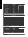
Integrated Peripherals
CMOS Setup Utility-Copyright (C) 1984-2004 Award Software
Integrated Peripherals
IDE Function Setup
On-Chip Primary PCI IDE
On-Chip Secondary PCI IDE
USB Host Controller
USB Keyboard Support
USB Mouse Support
Serial-ATA 2(Internal PHY)
AC97 Audio
On-Chip LAN(nVIDIA)
Onboard Serial Port 1
Onboard Serial Port 2
Onboard Parallel Port
Parallel Port Mode
x ECP Mode Use DMA
Game Port Address
Midi Port Address
x Midi Port IRQ
CIR Port Address
x CIR Port IRQ
KLJI: Move
Enter: Select
F5: Previous Values
[Press Enter]
[Enabled]
[Enabled]
[V1.1+V2.0]
[Disabled]
[Disabled]
[Enabled]
[Auto]
[Auto]
[3F8/IRQ4]
[2F8/IRQ3]
[378/IRQ7]
[SPP]
3
[201]
[Disabled]
10
[Disabled]
11
+/-/PU/PD: Value
F6: Fail-Save Default
Item Help
Menu Level`
F10: Save
ESC: Exit
F7: Optimized Defaults
F1: General Help
CMOS Setup Utility-Copyright (C) 1984-2004 Award Software
Integrated Peripherals
IDE DMA transfer
[Enabled]
KLJI: Move
Enter: Select
F5: Previous Values
+/-/PU/PD: Value
F6: Fail-Save Default
Item Help
Menu Level`
F10: Save
ESC: Exit
F7: Optimized Defaults
F1: General Help
IDE Function Setup
CMOS Setup Utility-Copyright (C) 1984-2004 Award Software
IDE Function Setup
IDE Channel 0 Master RAID
IDE Channel 0 Slave RAID
IDE Channel 1 Master RAID
IDE Channel 1 Slave RAID
SATA Primary Master RAID
SATA Secndry Master RAID
KLJI: Move
Enter: Select
F5: Previous Values
GA-K8NS Motherboard
[Disabled]
[Disabled]
[Disabled]
[Disabled]
[Disabled]
[Disabled]
+/-/PU/PD: Value
F6: Fail-Save Default
- 40 -
Item Help
Menu Level`
F10: Save
ESC: Exit
F7: Optimized Defaults
F1: General Help
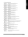
Enabled
Disabled
English
IDE Channel 0 Master RAID
Enable 1st master channel IDE RAID function.
Disable this function. (Default value)
IDE Channel 0 Slave RAID
Enabled
Disabled
Enable 1st slave channel IDE RAID function.
Disable this function. (Default value)
IDE Channel 1 Master RAID
Enabled
Disabled
Enable 2nd master channel IDE RAID function.
Disable this function. (Default value)
IDE Channel 1 Slave RAID
Enabled
Disabled
Enable 2nd slave channel IDE RAID function.
Disable this function. (Default value)
SATA Primary Master RAID
Enabled
Disabled
Enable 1st SATA RAID function.
Disable this function. (Default value)
SATA Secndry Master RAID
Enabled
Disabled
Enable 2nd SATA RAID function.
Disable this function. (Default value)
On-Chip Primary PCI IDE
Enabled
Disabled
Enable onboard 1st channel IDE port. (Default value)
Disable onboard 1st channel IDE port.
On-Chip Secondary PCI IDE
Enabled
Disabled
Enable onboard 2nd channel IDE port. (Default value)
Disable onboard 2nd channel IDE port.
USB Host Controller
Disabled
V1.1+V2.0
V1.1
Disable this function if you are not using onboard USB function.
Enable USB 1.1 and USB 2.0 controller. (Default value)
Only enable USB 1.1 controller.
USB Keyboard Support
Enabled
Disabled
Enable USB keyboard support.
Disable USB keyboard support. (Default value)
USB Mouse Support
Enabled
Disabled
Enable USB mouse support.
Disable USB mouse support. (Default value)
Serial-ATA 2 (Internal PHY)
Enabled
Disabled
AC97 Audio
Auto
Disabled
Enable Serial ATA support. (Default value)
Disable Serial ATA support.
Enable onboard AC'97 audio function. (Default value)
Disable this function.
- 41 -
BIOS Setup
English
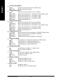
On-Chip LAN (nVIDIA)
Auto
Disabled
Auto-detect onboard LAN function. (Default value)
Disable onboard LAN function.
Onboard Serial Port 1
Auto
3F8/IRQ4
2F8/IRQ3
3E8/IRQ4
2E8/IRQ3
Disabled
BIOS will automatically setup the port 1 address.
Enable onboard Serial port 1 and address is 3F8. (Default value)
Enable onboard Serial port 1 and address is 2F8.
Enable onboard Serial port 1 and address is 3E8.
Enable onboard Serial port 1 and address is 2E8.
Disable onboard Serial port 1.
Onboard Serial Port 2
Auto
3F8/IRQ4
2F8/IRQ3
3E8/IRQ4
2E8/IRQ3
Disabled
BIOS will automatically setup the port 2 address.
Enable onboard Serial port 2 and address is 3F8.
Enable onboard Serial port 2 and address is 2F8. (Default value)
Enable onboard Serial port 2 and address is 3E8.
Enable onboard Serial port 2 and address is 2E8.
Disable onboard Serial port 2.
Onboard Parallel Port
378/IRQ7
278/IRQ5
Disabled
3BC/IRQ7
Enable onboard LPT port and address is 378/IRQ7. (Default value)
Enable onboard LPT port and address is 278/IRQ5.
Disable onboard LPT port.
Enable onboard LPT port and address is 3BC/IRQ7.
Parallel Port Mode
SPP
EPP
ECP
ECP+EPP
Using Parallel port as Standard Parallel Port. (Default value)
Using Parallel port as Enhanced Parallel Port.
Using Parallel port as Extended Capabilities Port.
Using Parallel port as ECP & EPP mode.
ECP Mode Use DMA
3
1
Set ECP Mode Use DMA to 3. (Default value)
Set ECP Mode Use DMA to 1.
Game Port Address
201
209
Disabled
Set Game Port Address to 201. (Default value)
Set Game Port Address to 209.
Disable this function.
Midi Port Address
300
330
Disabled
Midi Port IRQ
5
10
GA-K8NS Motherboard
Set Midi Port Address to 300.
Set Midi Port Address to 330.
Disable this function. (Default value)
Set Midi Port IRQ to 5.
Set Midi Port IRQ to 10. (Default value)
- 42 -
310
320
Disabled
CIR Port IRQ
5
11
English
CIR Port Address
Set CIR Port Address to 310.
Set CIR Port Address to 320.
Disable this function. (Default value)
Set CIR Port IRQ to 5.
Set CIR Port IRQ to 11. (Default value)
IDE DMA transfer access
Enabled
Disabled
Enable IDE DMA transfer access. (Default value)
Disable this function.
- 43 -
BIOS Setup
English
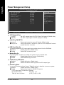
Power Management Setup
CMOS Setup Utility-Copyright (C) 1984-2004 Award Software
Power Management Setup
ACPI Suspend Type
Soft-Off by PWR-BTTN
PME Event Wake Up
Modem Ring On
S3 Resume by USB device
Resume by Alarm
x Day of Month Alarm
x Time (hh:mm:ss) Alarm
Power On by Mouse
Power On by Keyboard
x KB Power ON Password
AC Back Function
KLJI: Move
Enter: Select
F5: Previous Values
[S1(POS)]
[Instant-Off]
[Disabled]
[Disabled]
[Disabled]
[Disabled]
Everyday
0:0:0
[Disabled]
[Disabled]
Enter
[Soft-Off]
+/-/PU/PD: Value
F6: Fail-Save Default
Item Help
Menu Level`
[S1]
Set suspend type to
Power On Suspend under
ACPI OS
[S3]
Set suspend type to
Suspend to RAM under
ACPI OS
F10: Save
ESC: Exit
F7: Optimized Defaults
F1: General Help
ACPI Suspend Type
S1(POS)
S3(STR)
Set ACPI suspend type to S1/POS (Power On Suspend). (Default value)
Set ACPI suspend type to S3/STR (Suspend To RAM).
Soft-Off by PWR-BTTN
Instant-off
Delay 4 Sec.
Press power button then power off instantly. (Default value)
Press power button 4 seconds to power off. Enter suspend if button is
pressed less than 4 seconds.
PME Event Wake Up
This feature requires an ATX power supply that provides at least 1A on the 5VSB lead.
Disabled
Disable this function. (Default value)
Enabled
Enable PME as wake up event.
Modem Ring On
An incoming call via modem can awake the system from any suspend state.
Disabled
Disable Modem Ring on function. (Default value)
Enabled
Enable Modem Ring on function.
S3 Resume by USB Device
Disabled
Enable
Disable this function. (Default value)
Enable USB device wake up system from S3 suspend type.
Resume by Alarm
You can set "Resume by Alarm" item at "Enabled" and key in data/time to power on system.
Disabled
Disable this function. (Default value)
Enabled
Enable alarm function to POWER ON system.
If RTC Alarm Lead To Power On is Enabled.
Day of Month Alarm :
Everyday, 1~31
Time (hh: mm: ss) Alarm :
(0~23) : (0~59) : (0~59)
GA-K8NS Motherboard
- 44 -
Disabled
Double Click
Disabled this function. (Default value)
Double click on PS/2 mouse left button to power on system.
Power On by Keyboard
Disabled
Password
Keyboard 98
Disabled this function. (Default value)
Enter from 1 to 5 characters to set the keyboard power on password.
If there is a "POWER" button on your keyboard, you can press the key to
power on your system.
KB Power ON Password
When "Power On by Keyboard" set at Password, you can set the password here.
Enter
Input password(from 1 to 5 characters) and press Enter to set the password.
AC Back Function
Soft-Off
Full-On
Always in off state when AC back. (Default value)
Always power on the system when AC back.
- 45 -
BIOS Setup
English
Power On by Mouse
English
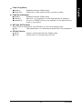
PnP/PCI Configurations
CMOS Setup Utility-Copyright (C) 1984-2004 Award Software
PnP/PCI Configurations
PCI 3 IRQ Assignment
PCI 4 IRQ Assignment
PCI 1/5 IRQ Assignment
PCI 2 IRQ Assignment
KLJI: Move
Enter: Select
F5: Previous Values
PCI 3 IRQ Assignment
Auto
3,4,5,7,9,10,11,12,14,15
PCI 4 IRQ Assignment
Auto
3,4,5,7,9,10,11,12,14,15
PCI 1/5 IRQ Assignment
Auto
3,4,5,7,9,10,11,12,14,15
PCI 2 IRQ Assignment
Auto
3,4,5,7,9,10,11,12,14,15
GA-K8NS Motherboard
[Auto]
[Auto]
[Auto]
[Auto]
+/-/PU/PD: Value
F6: Fail-Save Default
Item Help
Menu Level`
F10: Save
ESC: Exit
F7: Optimized Defaults
F1: General Help
Auto assign IRQ to PCI 3. (Default value)
Set IRQ 3,4,5,7,9,10,11,12,14,15 to PCI 3.
Auto assign IRQ to PCI 4. (Default value)
Set IRQ 3,4,5,7,9,10,11,12,14,15 to PCI 4.
Auto assign IRQ to PCI 1/5. (Default value)
Set IRQ 3,4,5,7,9,10,11,12,14,15 to PCI 1/PCI5.
Auto assign IRQ to PCI 2. (Default value)
Set IRQ 3,4,5,7,9,10,11,12,14,15 to PCI 2.
- 46 -
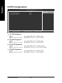
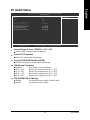
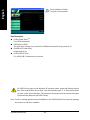
CMOS Setup Utility-Copyright (C) 1984-2004 Award Software
PC Health Status
Vcore
DDR25V
+3.3V
+12V
Current CPU Temperature
Current CPU FAN Speed
Current SYSTEM FAN Speed
CPU Warning Temperature
CPU FAN Fail Warning
SYSTEM FAN Fail Warning
KLJI: Move
Enter: Select
F5: Previous Values
OK
OK
OK
OK
51°C
3125 RPM
0 RPM
[Disabled]
[Disabled]
[Disabled]
+/-/PU/PD: Value
F6: Fail-Save Default
Item Help
Menu Level`
F10: Save
ESC: Exit
F7: Optimized Defaults
F1: General Help
Current Voltage (V) Vcore / DDR25V / +3.3V / +12V
Detect system's voltage status automatically.
Current CPU Temperature
Detect CPU temperature automatically.
Current CPU/SYSTEM FAN Speed (RPM)
Detect CPU/system fan speed status automatically.
CPU Warning Temperature
Disabled
60 oC / 140 o F
70 oC / 158 o F
80 oC / 176 o F
90 oC / 194 o F
Don't monitor current temperature.
Monitor CPU temperature at 60 oC /
Monitor CPU temperature at 70 oC /
Monitor CPU temperature at 80 oC /
Monitor CPU temperature at 90 oC /
140oF.
158oF.
176oF.
194oF.
CPU/SYSTEM FAN Fail Warning
Disabled
Enabled
Fan warning function disable. (Default value)
Fan warning function enable.
- 47 -
BIOS Setup
English
PC Health Status
English
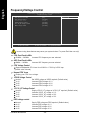
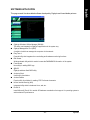
Frequency/Voltage Control
CMOS Setup Utility-Copyright (C) 1984-2004 Award Software
Frequency/Voltage Control
CPU OverClock in MHz
AGP OverClock in MHz
CPU Voltage Control
Normal CPU Vcore
VDDQ Voltage Control
VCC12_HT Voltage Control
DDR voltage control
[200]
[66]
[Normal]
1.550V
[Normal]
[Normal]
[Normal]
KLJI: Move
Enter: Select
F5: Previous Values
+/-/PU/PD: Value
F6: Fail-Save Default
Item Help
Menu Level`
F10: Save
ESC: Exit
F7: Optimized Defaults
F1: General Help
Incorrect using these features may cause your system broken. For power End-User use only!
CPU OverClock in MHz
200MHz ~ 300MHz
AGP OverClock in MHz
66MHz ~ 100MHz
Increase CPU frequency as user selected.
Increase AGP frequency as user selected.
CPU Voltage Control
Supports adjustable CPU Vcore from 0.800V to 1.700V by 0.025V step.
(Default value: Normal)
Normal CPU Vcore
Display your CPU Vcore voltage.
VDDQ Voltage Control
Normal
+0.1V
+0.2V
+0.3V
Set VDDQ voltage as VDDQ required. (Default value)
Increase VDDQ voltage +0.1V.
Increase VDDQ voltage +0.2V.
Increase VDDQ voltage +0.3V.
VCC12_HT Voltage Control
Normal
+0.1V
+0.2V
+0.3V
DDR voltage control
Normal
+0.1V
+0.2V
+0.3V
GA-K8NS Motherboard
Supply VCC12_HT voltage as VCC12_HT required. (Default value)
Increase VCC12_HT voltage +0.1V.
Increase VCC12_HT voltage +0.2V.
Increase VCC12_HT voltage +0.3V.
Supply DDR voltage as DDR required. (Default value)
Increase DDR voltage +0.1V.
Increase DDR voltage +0.2V.
Increase DDR voltage +0.3V.
- 48 -
English
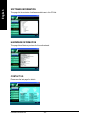
Top Performance
CMOS Setup Utility-Copyright (C) 1984-2004 Award Software
`
`
`
`
`
`
`
Standard CMOS Features
Advanced BIOS Features
Integrated Peripherals Top Performance
Power Management Setup
Disabled.........................[]
PnP/PCI Configurations
Enabled..........................[ ]
PC Health Status
Frequency/Voltage Control
ESC: Quit
F8: Q-Flash
Top Performance
Load Fail-Safe Defaults
Load Optimized Defaults
Set Supervisor Password
Set User Password
Save & Exit Setup
Exit Without Saving
KLJI: Select Item
KL: Move
ENTER: Accept
F10: Save & Exit Setup
ESC: Abort
System will be set in best performance configuration..
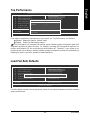
If you wish to maximize the performance of your system, set "Top Performance" as "Enabled".
Disabled Disable this function. (Default Value)
Enabled Enable Top Performance function.
"Top Performance" will increase H/W working speed. Different system configuration (both H/W
component and OS) will effect the result. For example, the same H/W configuration might not run
properly with Windows XP, but works smoothly with Windows NT. Therefore, if your system is not
perform enough, the reliability or stability problem will appear sometimes, and we will recommend you
disabling the option to avoid the problem as mentioned above.
Load Fail-Safe Defaults
CMOS Setup Utility-Copyright (C) 1984-2004 Award Software
`
`
`
`
`
`
`
Standard CMOS Features
Advanced BIOS Features
Integrated Peripherals
Power Management Setup
PnP/PCI Configurations
PC Health Status
Frequency/Voltage Control
Top Performance
Load Fail-Safe Defaults
Load Optimized Defaults
Set Supervisor Password
Load Fail-Safe DefaultsSet
(Y/N)?
User NPassword
Save & Exit Setup
Exit Without Saving
KLJI: Select Item
F10: Save & Exit Setup
ESC: Quit
F8: Q-Flash
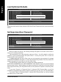
Load Fail-Safe Defaults
Fail-Safe defaults contain the most appropriate values of the system parameters that allow minimum
system performance.
- 49 -
BIOS Setup
English
Load Optimized Defaults
CMOS Setup Utility-Copyright (C) 1984-2004 Award Software
`
`
`
`
`
`
`
Standard CMOS Features
Advanced BIOS Features
Integrated Peripherals
Power Management Setup
PnP/PCI Configurations
PC Health Status
Frequency/Voltage Control
Top Performance
Load Fail-Safe Defaults
Load Optimized Defaults
Set Supervisor Password
Load Optimized DefaultsSet
(Y/N)?
N
User Password
Save & Exit Setup
Exit Without Saving
KLJI: Select Item
F10: Save & Exit Setup
ESC: Quit
F8: Q-Flash
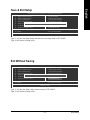
Load Optimized Defaults
Selecting this field loads the factory defaults for BIOS and Chipset Features which the system automatically
detects.
Set Supervisor/User Password
CMOS Setup Utility-Copyright (C) 1984-2004 Award Software
`
`
`
`
`
`
`
Standard CMOS Features
Advanced BIOS Features
Integrated Peripherals
Power Management Setup
Enter Password:
PnP/PCI Configurations
Top Performance
Load Fail-Safe Defaults
Load Optimized Defaults
Set Supervisor Password
Set User Password
Save & Exit Setup
Exit Without Saving
PC Health Status
Frequency/Voltage Control
KLJI: Select Item
F10: Save & Exit Setup
ESC: Quit
F8: Q-Flash
Change/Set/Disable Password
When you select this function, the following message will appear at the center of the screen to
assist you in creating a password.
Type the password, up to eight characters, and press <Enter>. You will be asked to confirm the
password. Type the password again and press <Enter>. You may also press <Esc> to abort the
selection and not enter a password.
To disable password, just press <Enter> when you are prompted to enter password. A message
"PASSWORD DISABLED" will appear to confirm the password being disabled. Once the password is
disabled, the system will boot and you can enter Setup freely.
The BIOS Setup program allows you to specify two separate passwords:
SUPERVISOR PASSWORD and a USER PASSWORD. When disabled, anyone may access all BIOS
Setup program function. When enabled, the Supervisor password is required for entering the BIOS
Setup program and having full configuration fields, the User password is required to access only basic
items.
If you select "System" at "Password Check" in Advance BIOS Features Menu, you will be
prompted for the password every time the system is rebooted or any time you try to enter Setup Menu.
If you select "Setup" at "Password Check" in Advance BIOS Features Menu, you will be prompted
only when you try to enter Setup.
GA-K8NS Motherboard
- 50 -
English
Save & Exit Setup
CMOS Setup Utility-Copyright (C) 1984-2004 Award Software
`
`
`
`
`
`
`
Standard CMOS Features
Advanced BIOS Features
Integrated Peripherals
Power Management Setup
PnP/PCI Configurations
PC Health Status
Frequency/Voltage Control
Top Performance
Load Fail-Safe Defaults
Load Optimized Defaults
Set Supervisor Password
Save to CMOS and EXITSet
(Y/N)?
User Y
Password
Save & Exit Setup
Exit Without Saving
KLJI: Select Item
F10: Save & Exit Setup
ESC: Quit
F8: Q-Flash
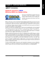
Save & Exit Setup
Type "Y" will quit the Setup Utility and save the user setup value to RTC CMOS.
Type "N" will return to Setup Utility.
Exit Without Saving
CMOS Setup Utility-Copyright (C) 1984-2004 Award Software
`
`
`
`
`
`
`
Standard CMOS Features
Advanced BIOS Features
Integrated Peripherals
Power Management Setup
PnP/PCI Configurations
PC Health Status
Frequency/Voltage Control
Top Performance
Load Fail-Safe Defaults
Load Optimized Defaults
Set Supervisor Password
Quit Without Saving (Y/N)?
N Password
Set User
Save & Exit Setup
Exit Without Saving
KLJI: Select Item
F10: Save & Exit Setup
ESC: Quit
F8: Q-Flash
Abandon all Data
Type "Y" will quit the Setup Utility without saving to RTC CMOS.
Type "N" will return to Setup Utility.
- 51 -
BIOS Setup
English
GA-K8NS Motherboard
- 52 -
English
Chapter 4 Technical Reference
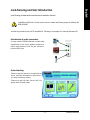
@BIOS Introduction
TM
Gigabyte announces @BIOS
Windows BIOS Live Update Utility
Have you ever updated BIOS by yourself? Or like many
other people, you just know what BIOS is, but always
hesitate to update it? Because you think updating newest BIOS is unnecessary and actually you don't know
how to update it.
Maybe not like others, you are very experienced in BIOS updating and spend quite a lot of time to do it. But
of course you don't like to do it too much. First, download different BIOS from website and then switch the
operating system to DOS mode. Secondly, use different flash utility to update BIOS. The above process is
not a interesting job. Besides, always be carefully to store the BIOS source code correctly in your disks as if
you update the wrong BIOS, it will be a nightmare.
Certainly, you wonder why motherboard vendors could not just do something right to save your time and
effort and save you from the lousy BIOS updating work? Here it comes! Now Gigabyte announces @BIOS - the first Windows BIOS live update utility. This is a smart BIOS update software. It could help you to
download the BIOS from internetand update it. Not like the other BIOS update software, it's a Windows
utility. With the help of "@BIOS", BIOS updating is no more than a click.
Besides, no matter which mainboard you are using, if it's a Gigabyte's product, @BIOS help you to maintain
the BIOS. This utility could detect your correct mainboard model and help you to choose the BIOS accordingly.
It then downloads the BIOS from the nearest Gigabyte ftp site automatically. There are several different
choices; you could use "Internet Update" to download and update your BIOS directly. Or you may want to
keep a backup for your current BIOS, just choose "Save Current BIOS" to save it first. You make a wise
choice to use Gigabyte, and @BIOS update your BIOS smartly. You are now worry free from updating wrong
BIOS, and capable to maintain and manage your BIOS easily. Again, Gigabyte's innovative product erects a
milestone in motherboard industries.
For such a wonderful software, how much it costs? Impossible! It's free! Now, if you buy a Gigabyte's
motherboard, you could find this amazing software in the attached driver CD. But please remember, connected to internet at first, then you could have a internet BIOS update from your Gigabyte @BIOS.
- 53 -
Technical Reference
English
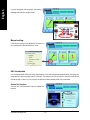
Flash BIOS Method Introduction
Method 1 : Q-Flash Utility
TM
Q-Flash is a BIOS flash utility embedded in Flash ROM.
TM
With this utility, users only have to stay in the BIOS menu
when they want to update BIOS. Q-Flash™ allows users
to flash BIOS without any utility in DOS or Windows. Using Q-Flash indicating no more fooling around with any complicated instructions and operating
TM
system since it is in the BIOS menu.
Please note that because updating BIOS has potential risk, please do it with caution!!
We are sorry that Gigabyte Technology Co., Ltd is not responsible for damages of
system because of incorrect manipulation of updating BIOS to avoid any claims from
end-users.
Before You Begin:
Before you start updating BIOS with the Q-Flash utility, please follow the steps below first.
TM
1. Download the latest BIOS for your motherboard from Gigabyte's website.
2. Extract the BIOS file downloaded and save the BIOS file (the one with model name.Fxx. For
example, 8KNXPU.Fba) to a floppy disk.
3. Reboot your PC and press Del to enter BIOS menu.
The BIOS upgrading guides below are separated into two parts.
If your motherboard has dual-BIOS, please refer to Part One.
If your motherboard has single-BIOS, please refer to Part Two.
GA-K8NS Motherboard
- 54 -
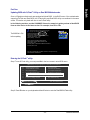
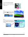
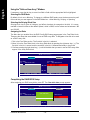
Updating BIOS with Q-Flash Utility on Dual BIOS Motherboards.
TM
Some of Gigabyte motherboards are equipped with dual BIOS. In the BIOS menu of the motherboards
supporting Q-Flash and Dual BIOS, the Q-Flash utility and Dual BIOS utility are combined in the same
screen. This section only deals with how to use Q-Flash utility.
In the following sections, we take GA-8KNXP Ultra as the example to guide you how to flash BIOS
from an older version to the latest version. For example, from Fa3 to Fba.
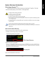
Award Modular BIOS v6.00PG, An Energy Star Ally
Copyright (C) 1984-2003, Award Software, Inc.
The BIOS file is Fa3
Intel i875P AGPset BIOS for 8KNXP Ultra Fa3
Check System Health OK , VCore = 1.5250
Main Processor : Intel Pentium(R) 4 1.6GHz (133x12)
<CPUID : 0F27 Patch ID : 0027>
Memory Testing : 131072K OK
before updating
Memory Frequency 266 MHz in Single Channel
Primary Master : FUJITSU MPE3170AT ED-03-08
Primary Slave : None
Secondary Master : CREATIVEDVD-RM DVD1242E BC101
Secondary Slave : None
Press DEL to enter SETUP / Dual BIOS / Q-Flash / F9 For Xpress Recovery
08/07/2003-i875P-6A79BG03C-00
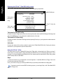
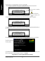
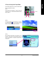
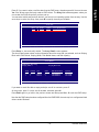
Entering the Q-Flash utility:
TM
Step1: To use Q-Flash utility, you must press Del in the boot screen to enter BIOS menu.
CMOS Setup Utility-Copyright (C) 1984-2003 Award Software
`
`
Standard CMOS Features
Advanced BIOS Features
`
`
Integrated Peripherals
Load Optimized Defaults
Power Management Setup
Set Supervisor Password
Enter Dual BIOS/Q-Flash Utility
(Y/N)?
Y
PnP/PCI Configurations
Set User
Password
`
`
`
Top Performance
Load Fail-Safe Defaults
PC Health Status
Save & Exit Setup
Frequency/Voltage Control
Exit Without Saving
KLJI: Select Item
F10: Save & Exit Setup
ESC: Quit
F8: Dual BIOS/Q-Flash
Step 2: Press F8 button on your keyboard and then Y button to enter the Dual BIOS/Q-Flash utility.
- 55 -
Technical Reference
English
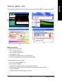
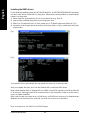
Part One:
Exploring the Q-Flash / Dual BIOS utility screen
English
TM
The Q-Flash / Dual BIOS utility screen consists of the following key components.
Dual BIOS Utility
Boot From......................................... Main Bios
Main ROM Type/Size............................. SST 49LF003A
Backup ROM Type/Size......................... SST 49LF003A
Dual BIOS utility bar
512K
512K
Wide Range Protection Disable
Boot From Main Bios
Auto Recovery Enable
Halt On Error Disable
Copy Main ROM Data to Backup
Load Default Settings
Save Settings to CMOS
Task menu for
Dual BIOS
utility
Task menu for
TM
Q-Flash utility
Enter : Run
Q-Flash Utility
Load Main BIOS from Floppy
Load Backup BIOS from Floppy
Save Main BIOS to Floppy
Save Backup BIOS to Floppy
KL:Move
ESC:Reset
F10:Power Off
TM
Q-Flash utility title
bar
Action bar
Task menu for Dual BIOS utility:
Contains the names of eight tasks and two item showing information about the BIOS ROM type. Blocking a task
and pressing Enter key on your keyboard to enable execution of the task.
Task menu for Q-Flash utility:
Contains the names of four tasks. Blocking a task and pressing Enter key on your keyboard to enable execution
of the task.
Action bar:
Contains the names of four actions needed to operate the Q-Flash/Dual BIOS utility. Pressing the buttons
mentioned on your keyboards to perform these actions.
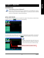
Using the Q-Flash utility:
TM
This section tells you how to update BIOS using the Q-Flash utility. As described in the "Before you begin"
section above, you must prepare a floppy disk having the BIOS file for your motherboard and insert it to your
computer. If you have already put the floppy disk into your system and have entered the Q-Flash utility, please
follow the steps below to flash BIOS.
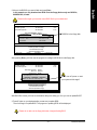
Steps:
1. Press arrow buttons on your keyboard to move the light bar to "Load Main BIOS from Floppy" item in the
Q-Flash menu and press Enter button.
Later, you will see a box pop up showing the BIOS files you previously downloaded to the floppy disk.
If you want to save the current BIOS for backup purpose, you can begin Step 1 with "Save Main BIOS
to Floppy" item.
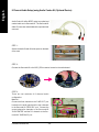
GA-K8NS Motherboard
- 56 -
In this example, we only download one BIOS file to the floppy disk so only one BIOS file,
8KNXPU.Fba, is listed.
Please confirm again you have the correct BIOS file for your motherboard.
Dual BIOS Utility
Boot From......................................... Main Bios
Main ROM Type/Size............................. SST 49LF003A
Backup ROM Type/Size......................... SST 49LF003A
512K
512K
Wide Range Protection Disable
Boot
From found
Main Bios
1 file(s)
512K
Auto Recovery Enable
Halt On Error Disable
Total size: 1.39M
Free size: 911.50K
Copy Main ROM Data to Backup
F5 : Refresh
DEL : Delete
Load Default Settings
Save Settings to CMOS
BIOS file in the floppy disk.
8KNXPU.Fba
Enter : Run
Q-Flash Utility
Load Main BIOS from Floppy
Load Backup BIOS from Floppy
Save Main BIOS to Floppy
Save Backup BIOS to Floppy
KL:Move
ESC:Reset
F10:Power Off
After pressing Enter, you'll then see the progress of reading the BIOS file from the floppy disk.
Dual BIOS Utility
Boot From......................................... Main Bios
Main ROM Type/Size............................. SST 49LF003A
Backup ROM Type/Size......................... SST 49LF003A
512K
512K
Wide Range Protection Disable
Boot From Main Bios
Auto Recovery Enable
Halt
Error
Disable
Reading BIOS
fileOn
from
floppy...
Copy Main ROM Data to Backup
>>>>>>>>>>>>......................
Load Default Settings
to CMOS
Don't Turn Off Save
PowerSettings
Or Reset
System
Enter : Run
Do not trun off power or reset
your system at this stage!!
Q-Flash Utility
Load Main BIOS from Floppy
Load Backup BIOS from Floppy
Save Main BIOS to Floppy
Save Backup BIOS to Floppy
KL:Move
ESC:Reset
F10:Power Off
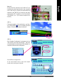
After BIOS file is read, you'll see a confirmation dialog box asking you "Are you sure to update BIOS?"
3. Press Y button on your keyboard after you are sure to update BIOS.
Then it will begin to update BIOS. The progress of updating BIOS will be displayed.
Please do not take out the floppy disk when it begins flashing BIOS.
- 57 -
Technical Reference
English
2. Move to the BIOS file you want to flash and press Enter.
English
4. Press any keys to return to the Q-Flash menu when the BIOS updating procedure is completed.
Dual BIOS Utility
Boot From......................................... Main Bios
Main ROM Type/Size............................. SST 49LF003A
Backup ROM Type/Size......................... SST 49LF003A
512K
512K
Wide Range Protection Disable
Boot From Main Bios
Auto Recovery Enable
Halt On Error Disable
Copy!!Main
to Backup
CopyROM
BIOSData
completed
- Pass !!
Load Default Settings
Please
press
any key
to continue
Save
Settings
to CMOS
Enter : Run
Q-Flash Utility
Load Main BIOS from Floppy
Load Backup BIOS from Floppy
Save Main BIOS to Floppy
Save Backup BIOS to Floppy
KL:Move
ESC:Reset
F10:Power Off
You can repeat Step 1 to 4 to flash the backup BIOS, too.
5. Press Esc and then Y button to exit the Q-Flash utility. The computer will restart automatically after you
exit Q-Flash.
Dual BIOS Utility
Boot From......................................... Main Bios
Main ROM Type/Size............................. SST 49LF003A
Backup ROM Type/Size......................... SST 49LF003A
512K
512K
Wide Range Protection Disable
Boot From Main Bios
Auto Recovery Enable
Halt On Error Disable
Copy Main
to RESET
Backup ?
AreROM
you Data
sure to
Load Default Settings
[Enter]Save
to continure
to abort...
Settingsorto[Esc]
CMOS
Enter : Run
Q-Flash Utility
Load Main BIOS from Floppy
Load Backup BIOS from Floppy
Save Main BIOS to Floppy
Save Backup BIOS to Floppy
KL:Move
ESC:Reset
F10:Power Off
After system reboots, you may find the BIOS version on your boot screen becomes the one you flashed.
Award Modular BIOS v6.00PG, An Energy Star Ally
Copyright (C) 1984-2003, Award Software, Inc.
The BIOS file becomes
Fab after updating
Intel i875P AGPset BIOS for 8KNXP Ultra Fba
Check System Health OK , VCore = 1.5250
Main Processor : Intel Pentium(R) 4 1.6GHz (133x12)
<CPUID : 0F27 Patch ID : 0027>
Memory Testing : 131072K OK
Memory Frequency 266 MHz in Single Channel
Primary Master : FUJITSU MPE3170AT ED-03-08
Primary Slave : None
Secondary Master : CREATIVEDVD-RM DVD1242E BC101
Secondary Slave : None
Press DEL to enter SETUP / Dual BIOS / Q-Flash / F9 For Xpress Recovery
09/23/2003-i875P-6A79BG03C-00
GA-K8NS Motherboard
- 58 -
CMOS Setup Utility-Copyright (C) 1984-2003 Award Software
`
`
Standard CMOS Features
Advanced BIOS Features
Top Performance
Load Fail-Safe Defaults
`
`
Integrated Peripherals
Power Management Setup
Load Optimized Defaults
Set Supervisor Password
`
`
PnP/PCI Configurations
PC Health Status
Set User Password
Save & Exit Setup
`
Frequency/Voltage Control
Exit Without Saving
Press Enter on
your keyboard
KLJI: Select Item
F10: Save & Exit Setup
ESC: Quit
F8: Dual BIOS/Q-Flash
CMOS Setup Utility-Copyright (C) 1984-2003 Award Software
`
Standard CMOS Features
Top Performance
`
`
Advanced BIOS Features
Integrated Peripherals
Load Fail-Safe Defaults
Load Optimized Defaults
`
`
Power Management Setup
Set Supervisor Password
Load Fail-Safe DefaultsSet
(Y/N)?
PnP/PCI Configurations
User YPassword
`
`
PC Health Status
Frequency/Voltage Control
Press Y on your
keyboard to load
defaults.
Save & Exit Setup
Exit Without Saving
KLJI: Select Item
F10: Save & Exit Setup
ESC: Quit
F8: Dual BIOS/Q-Flash
7. Select Save & Exit Setup item to save the settings to CMOS and exit the BIOS menu.
System will reboot after you exit the BIOS menu. The procedure is completed.
CMOS Setup Utility-Copyright (C) 1984-2003 Award Software
`
Standard CMOS Features
Top Performance
`
`
Advanced BIOS Features
Integrated Peripherals
Load Fail-Safe Defaults
Load Optimized Defaults
`
`
Power Management Setup
Set Supervisor Password
Save to CMOS and EXIT
Y
PnP/PCI Configurations
Set(Y/N)?
User Password
`
`
PC Health Status
Frequency/Voltage Control
Save & Exit Setup
Exit Without Saving
Press Y on your
keyboard to save
and exit.
KLJI: Select Item
F10: Save & Exit Setup
ESC: Quit
F8: Dual BIOS/Q-Flash
- 59 -
Technical Reference
English
6. Press Del to enter BIOS menu after system reboots. When you are in BIOS menu, move to Load FailSafe Defaults item and press Enter to load BIOS Fail-Safe Defaults. Normally the system redetects all
devices after BIOS has been upgraded. Therefore, we highly recommend reloading the BIOS defaults
after BIOS has been upgraded.
English
Part Two:
Updating BIOS with Q-Flash Utility on Single-BIOS Motherboards.
TM
This part guides users of single-BIOS motherboards how to update BIOS using the Q-Flash™ utility.
Entering the Q-Flash utility:
TM
Step1: To use the Q-Flash utility, you must press Del in the boot screen to enter BIOS menu.
CMOS Setup Utility-Copyright (C) 1984-2003 Award Software
`
`
Standard CMOS Features
Advanced BIOS Features
`
`
Integrated Peripherals
Load Optimized Defaults
Power Management Setup
Set Supervisor Password
Enter Q-Flash Utility (Y/N)?
PnP/PCI Configurations
Set UserYPassword
`
`
`
Top Performance
Load Fail-Safe Defaults
PC Health Status
Save & Exit Setup
Frequency/Voltage Control
Exit Without Saving
KLJI: Select Item
F10: Save & Exit Setup
ESC: Quit
F8: Q-Flash
Step 2: Press F8 button on your keyboard and then Y button to enter the Q-Flash utility.
Exploring the Q-Flash utility screen
TM
The Q-FlashBIOS utility screen consists of the following key components.
Q-Flash Utility V1.30
Flash Type/Size.............................. SST 49LF003A
Task menu for
TM
Q-Flash utility
256K
Q-Flash TM utility bar
Keep DMI Data
Enable
Update BIOS from Floppy
Save BIOS to Floppy
Enter : Run
KL:Move
ESC:Reset
F10:Power Off
Action bar
Task menu for Q-Flash utility:
Contains the names of three tasks. Blocking a task and pressing Enter key on your keyboard to enable execution of the task.
Action bar:
Contains the names of four actions needed to operate the Q-Flash utility. Pressing the buttons mentioned on
your keyboards to perform these actions.
GA-K8NS Motherboard
- 60 -
TM
This section tells you how to update BIOS using the Q-Flash utility. As described in the "Before you begin"
section above, you must prepare a floppy disk having the BIOS file for your motherboard and insert it to your
computer. If you have already put the floppy disk into your system and have entered the Q-Flash utility, please
follow the steps below to flash BIOS.
Steps:
1. Press arrow buttons on your keyboard to move the light bar to "Update BIOS from Floppy" item in the
Q-Flash menu and press Enter button.
Later, you will see a box pop up showing the BIOS files you previously downloaded to the floppy disk.
If you want to save the current BIOS for backup purpose, you can begin Step 1 with "Save BIOS to
Floppy" item.
2. Move to the BIOS file you want to flash and press Enter.
In this example, we only download one BIOS file to the floppy disk so only one BIOS file,
8GE800.F4, is listed.
Please confirm again you have the correct BIOS file for your motherboard.
Q-Flash Utility V1.30
Flash Type/Size.............................. SST 49LF003A
8GE800.F4
Keep DMI Data
Enable
Update BIOS from Floppy
file(s)tofound
Save 1BIOS
Floppy
Enter : Run
Total size:KL:Move
1.39M
F5 : Refresh
256K
BIOS file in the floppy disk.
256K
ESC:ResetFree size:1.14M
F10:Power Off
DEL : Delete
Q-Flash Utility V1.30
Flash Type/Size.............................. SST 49LF003A
256K
Keep DMI Data
Enable
Reading BIOS
file from
Update
BIOSfloppy...
from Floppy
>>>>>>>>>>>>......................
Save BIOS to Floppy
Enter : Run
Don't Turn Off Power Or Reset System
KL:Move
ESC:Reset
F10:Power Off
Do not trun off power or
reset your system at this
stage!!
After BIOS file is read, you'll see a confirmation dialog box asking you "Are you sure to update BIOS?"
Please do not take out the floppy disk when it begins flashing BIOS.
- 61 -
Technical Reference
English
Using the Q-Flash utility:
English
3. Press Y button on your keyboard after you are sure to update BIOS.
Then it will begin to update BIOS. The progress of updating BIOS will be shown at the same time.
Q-Flash Utility V1.30
Flash Type/Size.............................. SST 49LF003A
256K
The porcess of updating
BIOS
Keep DMI Data
Enable
Updating
BIOS
Update
BIOS
fromNow...
Floppy
>>>>>>>>>>>>>>........................
Save BIOS to Floppy
Enter : Run
Don't Turn Off Power Or Reset System
KL:Move
ESC:Reset
F10:Power Off
Do not trun off power or
reset your system at this
stage!!
4. Press any keys to return to the Q-Flash menu when the BIOS updating procedure is completed.
Q-Flash Utility V1.30
Flash Type/Size.............................. SST 49LF003A
256K
Keep DMI Data
Enable
Update BIOS from Floppy
!! Copy BIOS completed - Pass !!
Save BIOS to Floppy
Please press any key to continue..........
Enter : Run
KL:Move
ESC:Reset
F10:Power Off
5. Press Esc and then Y button to exit the Q-Flash utility. The computer will restart automatically after you
exit Q-Flash.
Q-Flash Utility V1.30
Flash Type/Size.............................. SST 49LF003A
256K
Keep DMI Data
Enable
Update BIOS from Floppy
Are you sure to RESET ?
Save BIOS to Floppy
[Enter] to continure or [Esc] to abort...
Enter : Run
KL:Move
ESC:Reset
F10:Power Off
After system reboots, you may find the BIOS version on your boot screen becomes the one you flashed.
Award Modular BIOS v6.00PG, An Energy Star Ally
Copyright (C) 1984-2003, Award Software, Inc.
The BIOS file becomes
Fab after updating
Intel 845GE AGPSet BIOS for 8GE800 F4
Check System Health OK
Main Processor : Intel Pentium(R) 4 1.7GHz (100x17.0)
<CPUID : 0F0A Patch ID : 0009>
Memory Testing : 122880K OK + 8192K Shared Memory
Primary Master : FUJITSU MPE3170AT ED-03-08
Primary Slave : None
Secondary Master : CREATIVEDVD-RM DVD1242E BC101
Secondary Slave : None
Press DEL to enter SETUP / Q-Flash
03/18/2003-I845GE-6A69YG01C-00
6. Press Del to enter BIOS menu after system reboots and "Load BIOS Fail-Safe Defaults". See how to Load
BIOS Fail-Safe Defaults, please kindly refer to Step 6 to 7 in Part One.
Congratulation!! You have updated BIOS successfully!!
GA-K8NS Motherboard
- 62 -
If you don't have DOS boot disk, we recommend that you used Gigabyte @BIOS ™ program to flash BIOS.
Press here.
2. Click Start/ Programs/ GIGABYTE/
@BIOS.
1. Click "@BIOS" item.
(1)
3.Click "3"
(2)
Click here
4. Please select @BIOS sever site,
then Click "OK".
(4)
(3)
Methods and steps:
1. Update BIOS through Internet:
a. Click "Internet Update" icon
b. Click "Update New BIOS" icon
c. Select @BIOS ™ sever
d. Select the exact model name on your motherboard
e. System will automatically download and update the BIOS.
2. Update BIOS NOT through Internet:
a. Do not click "Internet Update" icon
b. Click "Update New BIOS"
c. Please select "All Files" in dialog box while opening the old file.
d. Please search for BIOS unzip file, downloading from internet or any other methods.
(such as: K8NS.E19).
e. Complete update process following the instruction.
- 63 -
Technical Reference
English
Method 2 : @BIOS™ Utility
English
3. Save BIOS
In the very beginning, there is "Save Current BIOS" icon shown in dialog box. It means to save the current
BIOS version.
4. Check out supported motherboard and Flash ROM:
In the very beginning, there is "About this program" icon shown in dialog box. It can help you check out
which kind of motherboard and which brand of Flash ROM are supported.
Note:
a. In method I, if it shows two or more motherboard's model names to be selected, please make sure your
motherboard's model name again. Selecting wrong model name will cause the system unbooted.
b. In method II, be sure that motherboard's model name in BIOS unzip file are the same as your motherboard's.
Otherwise, your system won't boot.
c. In method I, if the BIOS file you need cannot be found in @BIOS™ server, please go onto Gigabyte's web
site for downloading and updating it according to method II.
d. Please note that any interruption during updating will cause system unbooted.
GA-K8NS Motherboard
- 64 -
Function Introduction
The installation of windows 98SE/2K/ME/XP is very simple. Please follow next step to install the
function!
Stereo Speakers Connection and Settings:
We recommend that you use the speaker with amplifier to acquire the best sound effect if the stereo output is
applied.
STEP 1:
Connect the stereo speakers or earphone to "Line
Out".
Line Out
STEP 2 :
Following installation of the audio driver, you find a
icon a Sound Effect
icon on the lower right hand
taskbar. Click the icon to select the function.
STEP 3:
Click "Speaker Configuration" then click on the left
selection bar and select "2CH Speaker" to complete
2 channel audio configuration.
- 65 -
Technical Reference
English
2- / 4- / 6- / 8- Channel Audio
English
4 Channel Analog Audio Output Mode
STEP 1 :
Connect the front channels to "Line Out", the rear
channels to "Line In".
Line Out Line In
STEP 2 :
Following installation of the audio driver, you find a
icon on the lower right hand
icon a Sound Effect
taskbar. Click the icon to select the function.
STEP 3 :
Click "Speaker Configuration" and select the "UAJ
Function". Then click on the left selection bar and
select "4CH Speaker" to complete 4 channel audio
configuration.
GA-K8NS Motherboard
- 66 -
English
6 Channel Analog Audio Output Mode
Use the back audio panel to connect the audio output
without any additional module.
STEP 1 :
Connect the front channels to "Line Out",the rear
channels to "Line In", and the Center/Subwoofer channels to "MIC In".
Line In
MIC In
Line Out
STEP 2 :
Following installation of the audio driver, you find a
icon a Sound Effect
icon on the lower right hand
taskbar. Click the icon to select the function.
STEP 3 :
Click "Speaker Configuration" and select the "UAJ
Function". Then click on the left selection bar and
select "6CH Speaker" to complete 6 channel audio
configuration.
- 67 -
Technical Reference
English
8 Channel Audio Setup (using Audio Combo Kit, Optional Device):
Audio Combo Kit offers SPDIF output, an optical and
coaxial cable and a Surround-Kit. The Surround-Kit
offers R/L surround, center/subwoofer output and rear
surround.
STEP 1 :
Secure the Audio Combo Kit at the panel on the back
of the case.
STEP 2 :
Connect the Surround-Kit to the SUR_CEN connector located on the motherboard.
STEP 3 :
There are two methods of 8 channel audio
configuration:
Method 1:
Connect the front channels to the "LINE OUT" port
located on the audio panel and the rear channels
to the Surround-Kit "REAR R/L" port. Connect the
center/subwoofer channels to the Surround-Kit
"SUB CENTER" and the R/L channels to the Surround-Kit "SUR BACK" port.
GA-K8NS Motherboard
- 68 -
English
Method 2:
Connect the front channels to the "LINE OUT" port
located on the audio panel and the rear channels
to the "LINE IN" port. Connect the center/subwoofer
channels to the "MIC IN" port located on the audio
panel and the R/L channels to the Surround-Kit
"SUR BACK" port. (This method requires UAJ
function)
STEP 4 :
Following installation of the audio driver, you find a
icon a Sound Effect
icon on the lower right hand
taskbar. Click the icon to select the function.
STEP 5 :
Click "Speaker Configuration" and select both the
"UAJ Function" and "Only Surround-Kit". Then click
on the left selection bar and select "8CH Speaker" to
complete 8 channel audio configuration.
Sound Effect Configuration:
At the sound effect menu, users can adjust
sound option settings as desired.
- 69 -
Technical Reference
English
SPDIF Output Device (Optional Device)
A "SPDIF output" device is available on the
motherboard. Cable with rear bracket is provided and
could link to the "SPDIF output" connector (As picture.)
For the further linkage to decoder, rear bracket provides coaxial cable and Fiber connecting port.
1. Connect the SPDIF output device to the rear
bracket of PC, and fix it with screw.
2. Connect SPDIF device to the motherboard.
3. Connect SPDIF to the SPDIF decoder.
GA-K8NS Motherboard
- 70 -
English
Jack-Sensing and UAJ Introduction
Jack-Sensing provides audio connectors error-detection function.
Install Microsoft DirectX8.1 or later version before to enable Jack-Sensing support for Windows 98/
98SE/2000/ME.
Jack-Sensing includes 2 parts: AUTO and MANUAL. Following is an example for 2 channels (Windows XP):
Introduction of audio connectors
You may connect CDROM, Walkman or others audio
input devices to Line In jack, speakers, earphone or
others output devices to Line Out jack, and microphone to MIC In jack.
Auto-detecting:
Please connect the devices to the right jacks as
above. A window will appear as right picture if
you setup the devices properly.
Please note that 3D audio function will only
appear when 3D audio inputs.
- 71 -
Technical Reference
English
If you set wrong with the connectors, the warning
message will come out as right picture.
Manual setting:
If the device picture shows different from what you
set, please press "Manual Selection" to set.
UAJ Introduction
UAJ (Universal Audio Jack) has a very smart feature: It will switch signal automatically when user plugs his
audio device to the wrong jack (Line-in/ Line-out). That means users do not need to worry the audio device
should be plug in Line-in or Line-out jack, the device will work perfectly after UAJ is activated.
Enable UAJ function:
You can click "UAJ Automatic" button to enable UAJ
function.
GA-K8NS Motherboard
- 72 -
What is Xpress Recovery (Note) ?
Xpress Recovery utility is an utility for backing up and restoring O.S. partition . If the hard
drive can not work properly, you can restore it to the original state.
1. It supports FAT16, FAT32, NTFS format.
2. It must be connected to IDE1 Master.
3. It's only allows you to install one O.S.
4. It must be used with IDE hard disk supporting HPA.
5. The first partition must be set as the boot partition. When the boot partition is backed up, please
do not change its size.
6. It is not recommend to use Xpress Recovery if you had ever used Ghost to return boot manager
to NTFS format.
1. System data and hard disk's reading/writing speed will affect backing up speed.
2. We recommend that you install Xpress Recovery immediately after installing O.S, drivers and
applications.
How to use the Xpress Recovery
There are two ways to enter the Xpress Recovery utility. (see the below)
1. Text Mode: press F9 during powering on the computer.
Press F9 during powering on the computer.
Award Modular BIOS v6.00PG, An Energy Star Al ly
Copyright (C) 1984-2002, Award Software, Inc.
Intel 865PE AGPSet BIOS for 8IPE1000MT F1
Check System Health OK
.
.
.
F9 For Xpress Recovery
Press DEL to enter SETUP / Q-Flash, F9 For Xpress Recovery
08/16/2002-I845GE-6A69YG01C-00
2. BMP Mode: boot from CD-ROM
Please go to "Advanced BIOS" setting menu and set boot from CD-ROM, then save and exit the BIOS menu.
Later, please insert MB driver CD into your drive when "Boot from CD:" appears at the bottom of the screen,
press any key to enter Xpress Recovery.
.
.
Verifying DMI Pool Data
Boot from CD:
Boot from CD:
(Note) Not all motherboard have this function.
- 73 -
Technical Reference
English
Xpress Recovery Introduction
English
You can highlight the item by using the arrows keys on your keyboard and enter key to enter
the menu.
Text Mode:
Xpress Recovery V1.0 (C) Copy Right 2003. GIGABYTE Technilogy CO. , Ltd.
1. Execute Backup Utility
2. Execute Restore Utility
3. Remove Backup Image
4. Set Password
5. Exit and Restart
BMP Mode:
Xpress Recovery V1.0 (C) Copy Right 2003. GIGABYTE Technilogy CO. , Ltd.
1. Execute Backup Utility
2. Execute Restore Utility
3. Remove Backup Image
4. Set Password
5. Exit and Restart
If you ever entered Xpress Recovery by booting from CD-ROM, you'll still be
directed to BMP mode by pressing F9 in the bootup screen.
GA-K8NS Motherboard
- 74 -
English
1. Execute Backup Utility:
Press B to Backup your System or Esc to Exit
The Backup utility will scan the system automatically and back it up.
The backed up data will be saved as a hidden image.
2. Execute Restore Utility:
This program will recover your system to factory default.
Press R to recover your system.
Press Esc to exit
Restore the backup image to the original state.
3. Remove Backup Image:
Are you sure to remove backup image? (Y/N)
Remove the backup image.
4. Set Password:
Please input the password(a~z or 0~9) or press ESC to exit.
This password must 4-16 characters.
You can set a password for Xpress Recovery to protect your hard disk data. Once this is done, password
input will be required to enter Xpress Recovery during the next system restart. If you wish to remove the
need for password entry, please click "Set Password" and under New Password/Confirm Password, make
sure there is no entry and then click "Enter" to remove this step.
5. Exit and Restart:
Exit and restart your computer.
- 75 -
Technical Reference
English
Serial ATA BIOS Setting Utility Introduction
RAID Levels
RAID (Redundant Array of Independent Disks) is a method of combining two hard disk drives into one
logical unit. The advantage of an Array is to provide better performance or data fault tolerance. Fault
tolerance is achieved through data redundant operation, where if one drives fails, a mirrored copy of the
data can be found on another drive. This can prevent data loss if the operating system fails or hangs.
The individual disk drives in an array are called members. The configuration information of each
member is recorded in the reserved sector that identifies the drive as a member. All disk members in
a formed disk array are recognized as a single physical drive to the operating system.
Hard disk drives can be combined together through a few different methods. The different methods are
referred to as different RAID levels. Different RAID levels represent different performance levels,
security levels and implementation costs. The RAID levels which the nVIDIA nForce3 250 chipset
supports are RAID 0, RAID 1, and JBOD.
RAID 0 (Striping)
RAID 0 reads and writes sectors of data interleaved between multiple drives. If any disk member fails,
it affects the entire array. The disk array data capacity is equal to the number of drive members times
the capacity of the smallest member. The striping block size can be set from 4KB to 64KB. RAID 0 does
not support fault tolerance.
RAID 1 (Mirroring)
RAID 1 writes duplicate data onto a pair of drives and reads both sets of data in parallel. If one of the
mirrored drives suffers a mechanical failure or does not respond, the remaining drive will continue to
function. Due to redundancy, the drive capacity of the array is the capacity of the smallest drive.
Under a RAID 1 setup, an extra drive called the spare drive can be attached. Such a drive will be
activated to replace a failed drive that is part of a mirrored array. Due to the fault tolerance, if any RAID
1 drive fails, data access will not be affected as long as there are other working drives in the array.
JBOD (Spanning)
A spanning disk array is equal to the sum of the all drives when the drives used are having different
capacities. Spanning stores data onto a drive until it is full, then proceeds to store files onto the next
drive in the array. When any disk member fails, the failure affects the entire array. JBOD is not really
a RAID and does not support fault tolerance.
GA-K8NS Motherboard
- 76 -
1) Have ready your hard drives for RAID construction.
Note: To achieve best performance, it is recommended that the hard drives used are of similar make
and storage capacity.
2) Please attach the hard drive connectors to their appropriate location on the motherboard ie. IDE,
SCSI, or SATA.
3) Enter the motherboard BIOS and locate RAID setup (Please refer to the section on Integrated
Peripherals).
4) Enter RAID setup in the BIOS and select the RAID type (For instance, enter F10 to select NVIDIA
RAID; Ctrl + S to select Silicon Image).
5) Complete driver installation.
6) Complete RAID utility installation.
More information on steps 4 and 5 is provided. (For more detailed setup information, please visit our
website at http:\\www.gigabyte.com.tw)
Configuring the NVIDIA RAID BIOS
The NVRAID BIOS setup lets you choose the RAID array type and which hard drives you want to make
part of the array.
Entering the RAID BIOS Setup
1. After rebooting your computer, wait until you see the RAID software prompting you to press F10. The
RAID prompt appears as part of the system POST and boot process prior to loading the OS. You have
a few seconds to press F10 before the window disappears.
NVIDIA RAID IDE ROM BIOS 4.22
Copyright (C) 2003 NVIDIA Corp.
Detecting array ...
Press F10 to enter RAID setup utility ...
2. Press F10.
The NVIDIA RAID Utility - Define a New Array window appears (as Figure below).
NVDIA RAID Utility Feb 13 2004
- Define a New Array RAID Mode: Mirroring
Striping Block: Optimal
Free Disks
Loc
Disk Model Name
Array Disks
Loc
Disk Model Name
1.0.M
1.1.M
ST3120026AS
ST3120026AS
[J
J ] Add
[I
I ] Del
[F6] Back [F7] Finish [TAB] Navigate [KL
KL] Select [ENTER] Popup
KL
- 77 -
Technical Reference
English
Please follow the steps below to construct a complete RAID array:
English
Using the "Define a New Array" Window
If necessary, press the tab key to move from field to field until the appropriate field is highlighted.
Selecting the RAID Mode
By default, this is set to Mirroring. To change to a different RAID mode, press the down arrow key until
the mode that you want appears in the RAID Mode box - either Mirroring, Striping, or Spanning.
Selecting the Striping Block Size
Striping block size is given in kilobytes, and affects how data is arranged on the disk. It is recommended to leave this value at the default Optimal, which is 32KB, but the values can be between 4 KB
and 128 KB.
Assigning the Disks
The disks that you enabled from the RAID Config BIOS setup page appear in the Free Disks block.
These are the drives that are available for use as RAID array disks. To designate a free disk to be used
as a RAID array disk,
1. Tab to the Free Disks section. The first disk in the list is selected.
2. Move it from the Free Disks block to the Array Disks block by pressing the rightarrow key (J). The
first disk in the list is moved, and the next disk in the list is selected and ready to be moved.
3. Continue pressing the right-arrow key (J) until all the disks that you want to use as RAID array disks
appear in the Array Disks block.
NVDIA RAID Utility Feb 13 2004
- Define a New Array RAID Mode: Mirroring
Striping Block: Optimal
Free Disks
Loc
Disk Model Name
Array Disks
Loc
Disk Model Name
1.0.M
[J
J ] Add 1.1.M
ST3120026AS
ST3120026AS
[I
I ] Del
[F6] Back [F7] Finish [TAB] Navigate [KL
KL] Select [ENTER] Popup
KL
Completing the RAID BIOS Setup
After assigning your RAID array disks, press F7. The Clear disk data prompt appears.
NVDIA RAID Utility Feb 13 2004
- Define a New Array RAID Mode: Mirroring
Free Disks
Loc
Disk Model Name
Striping Block: Optimal
Array Disks
Clear disk data
Loc?
Disk Model Name
1.0.M
J ] Add 1.1.M
[J
[Y] YES [N] NO
ST3120026AS
ST3120026AS
[I
I ] Del
KL] Select [ENTER] Popup
[F6] Back [F7] Finish [TAB] Navigate [KL
KL
GA-K8NS Motherboard
- 78 -
NVDIA RAID Utility Feb 13 2004
- Array List Boot
Id
Status
Vendor
Array Model Name
BBS
2
Health
NVIDIA
MIRROR 111.79G
[Ctrl-X] Exit [KL
KL] Select [B] Set Boot [N] New Array [ENTER] Detail
KL
Press Enter to view and verify details. The Array Detail screen appears.
The Array Detail screen shows various information about the array that you selected, such as Striping
Block used, RAID Mode, Striping Width, Disk Model Name, and disk capacity.
Array 2 : NVIDIA MIRROR 111.79G
- Array Detail RAID Mode: Mirroring
Striping Width : 1
Striping Block 32K
Adapt
Channel
M/S
Index
Disk Model Name
Capacity
1
1
0
1
Master
Master
0
1
ST3120026AS
ST3120026AS
111.79GB
111.79GB
[R] Rebuild [D] Delete [C] Clear Disk [ENTER] Return
If you want to mark this disk as empty and wipe out all its contents, press C.
At the prompt, press Y to wipe out all the data, otherwise press N.
Press Enter again to go back to the previous screen and then press Ctrl + X to exit the RAID setup.
Now that the RAID setup has been configured from the RAID BIOS, the next step is to configure and load
drivers under Windows.
- 79 -
Technical Reference
English
Press Y if you want to wipe out all the data from the RAID array, otherwise press N. You must choose
Yes if the drives were previously used as RAID drives. The Array List window appears, where you
can review the RAID arrays that you have set up.
You can select a disk array as boot device if you want to boot operating system from an array. Use the
arrow keys to select the array, then press B to specify the array as bootable.
English
Installing the RAID drivers
For the Windows operating system (Win NT, WinXP, Win2000 ), for IDE RAID/SCSI/Serial ATA functioning,
the driver must first be transferred to a floppy disk. Please follow the steps below to complete driver
transfer to a floppy disk:
1) Please insert the provided driver CD into the hard disk drive eg. Drive D:
2) Insert a blank formatted floppy disk into the floppy disk drive.
3) Either from "Command Prompt" or DOS, please type in "D:\BootDrv\menu.exe"(Refer to Fig.1)
4) Information on all chipsets should be listed on the screen (Refer to Fig.2), please select the proper
chipset model.
Fig.1
Fig.2
(Note)
Your system will then automatically zip and transfer this driver file to the floppy disk.
After you complete the steps, boot from the Windows CD to install the RAID drivers.
When install Windows 2000 or Windows XP from HDDs in serial ATA controller, press F6 as Win2000
or XP boots up, then supply serial ATA controller driver by this floppy disk. Follow on-screen instructions to complete installation.
(Each time you add a new hard drive to a RAID array, the RAID driver will have to be installed under
Windows once for that hard drive. After that, the driver will not have to be installed.)
Note: In the menu list, IAA_RAID is Intel ICH5R chipset.
GA-K8NS Motherboard
- 80 -
English
- 81 -
Technical Reference
English
GA-K8NS Motherboard
- 82 -
English
Revision
ChapterHistory
5 Appendix
Install Drivers
Pictures below are shown in Windows XP
Insert the driver CD-title that came with your motherboard into your CD-ROM drive, the driver
CD-title will auto start and show the installation guide. If not, please double click the CD-ROM
device icon in "My computer", and execute the setup.exe.
INSTALL CHIPSET DRIVER
This page shows the drivers that need to be installed for the system. Click each item to install the driver
manually or switch to the
to install the drivers automatically.
The "Xpress Install" uses the"Click and Go" technology to install the drivers automatically. Just select the
will finish the installation for you automatically.
drivers you want then click the "GO" button. The
Massage: Some device drivers will restart your
system automatically. After restarting your system the
"Xpress Install" will continue to install other drivers.
We recommend that you install all components in the list.
- 83 -
Appendix
English
Driver installation finished !
You have to reboot system !
Item Description
nVIDIA System Driver (Note)
For nVIDIA chipset driver.
USB Patch for WinXP
This patch driver can help you to resolve the USB device wake up S3 hang up issue in XP.
RealTek AC97 Codec Driver
Realtek audio driver.
nVIDIA USB 2.0 Driver
For nVIDIA USB 2.0 enhanced host controller.
For USB2.0 driver support under Windows XP operating system, please use Windows Service
Pack. After install Windows Service Pack, it will show a question mark "?" in "Universal Serial Bus
controller" under "Device Manager". Please remove the question mark and restart the system
(System will auto-detect the right USB2.0 driver).
Note: If an Error message appears during the installation of the nVIDIA System Driver, ignore the message
and continue on with driver installation.
GA-K8NS Motherboard
- 84 -
This page reveals the value-added software developed by Gigabyte and its worldwide partners.
Gigabyte Windows Utilities Manager (GWUM)
This utility can integrate the Gigabyte's applications in the system tray.
Gigabyte Management Tool (GMT)
A useful tool which can manage the computer via the network.
EasyTune 4
Powerful utility that integrates the overclocking and hardware monitoring functions.
DMI Viewer
Windows based utility which is used to browse the DMI/SMBIOS information of the system.
Face-Wizard
New utility for adding BIOS logo.
@BIOS
Gigabyte windows flash BIOS utility.
Acrobat e-Book
Useful utility from Adobe.
Acrobat Reader
Popular utility from Adobe for reading .PDF file format documents.
Norton Internet Security (NIS)
Integrated utility which includes anti-virus, ads, etc.
DirectX 9
Install Microsoft DirectX 9 to enable 3D hardware acceleration that support for operating system to
achieve better 3D performence.
- 85 -
Appendix
English
SOFTWARE APPLICATION
English
SOFTWARE INFORMATION
This page list the contects of softwares and drivers in this CD title.
HARDWARE INFORMATION
This page lists all device you have for this motherboard.
CONTACT US
Please see the last page for details.
GA-K8NS Motherboard
- 86 -
Below is a collection of general asked questions. To check general asked questions based on a specific motherboard
model, please log on to http://tw.giga-byte.com/faq/faq.htm
Question 1: I cannot see some options that were included in previous BIOS after updating BIOS. Why?
Answer: Some advanced options are hidden in new BIOS version. Please press Ctrl and F1 keys after entering
BIOS menu and you will be able to see these options.
Questions 2: Why is the light of my keyboard/optical mouse still on after computer shuts down?
Answer: In some boards, a small amount of electricity is kept on standby after computer shuts down and that's why
the light is still on.
Question 3: Why cannot I use all functions in EasyTune ™ 4?
Answer: The availability of the listed functions in EasyTune ™ 4 depends on the MB chipset. If the chipset doesn't
support certain functions in EasyTune™ 4, these functions will be locked automatically and you will not be able to use
them.
Question 4: Why do I fail to install RAID and ATA drivers under Win 2000 and XP on boards that support RAID
function after I connect the boot HDD to IDE3 or IDE4 ?
Answer: First of all, you need to save some files in the CD-ROM to a floppy disk before installing drivers. You also
need to go through some rather different steps in the installation process. Therefore, we suggest that you refer to
the installation steps in the RAID manual at our website.
(Please download it at http://tw.giga-byte.com/support/user_pdf/raid_manual.pdf)
Question 5: How do I clear CMOS?
Answer: If your board has a Clear CMOS jumper, please refer to the Clear CMOS steps in the manual. If your board
doesn't have such jumper, you can take off the on-board battery to leak voltage to clear CMOS. Please refer to the
steps below:
Steps:
1. Turn off power.
2. Disconnect the power cord from MB.
3. Take out the battery gently and put it aside for about 10 minutes (Or you can use a
metal object to connect the positive and negative pins in the battery holder to make
them short for one minute).
4. Re-insert the battery to the battery holder.
5. Connect power cord to MB again and turn on power.
6. Press Del to enter BIOS and load Fail-Safe Defaults.
7. Save changes and reboot the system.
Question 6: Why does system seem unstable after updating BIOS?
Answer: Please remember to load Fail-Safe Defaults (Or Load BIOS Defaults) after flashing BIOS. However, if the
system instability still remains, please clear CMOS to solve the problem.
Question 7: Why do I still get a weak sound after turning up the speaker to the maximum volume?
Answer: Please make sure the speaker you are using is equipped with an internal amplifier. If not, please change
another speaker with power/amplifier and try again later.
- 87 -
Appendix
English
FAQ
English
Question 8: How do I disable onboard VGA card in order to add an external VGA card?
Answer: Gigabyte motherboards will auto-detect the external VGA card after it is plugged in, so you don't need to
change any setting manually to disable the onboard VGA.
Question 9: Why cannot I use the IDE 2?
Answer: Please refer to the user manual and check whether you have connected any cable that is not provided with
the motherboard package to the USB Over Current pin in the Front USB Panel. If the cable is your own cable, please
remove it from this pin and do not connect any of your own cables to it.
Question 10: Sometimes I hear different continuous beeps from computer after system boots up. What do these
beeps usually stand for?
Answer: The beep codes below may help you identify the possible computer problems. However, they are only for
reference purposes. The situations might differ from case to case.
JAMI BIOS Beep Codes
J AWARD BIOS Beep Codes
*Computer gives 1 short beep when system boots successfully.
1 short: System boots successfully
2 short: CMOS setting error
*Except for beep code 8, these codes are always fatal.
1 beep Refresh failure
1 long 1 short: DRAM or M/B error
2 beeps Parity error
1 long 2 short: Monitor or display card error
3 beeps Base 64K memory failure
1 long 3 short: Keyboard error
4 beeps Timer not operational
1 long 9 short: BIOS ROM error
5 beeps Processor error
Continuous long beeps: DRAM error
6 beeps 8042 - gate A20 failure
Continuous short beeps: Power error
7 beeps Processor exception interrupt error
8 beeps Display memory read/write failure
9 beeps ROM checksum error
10 beeps CMOS shutdown register read/write error
11 beeps Cache memory bad
Question 11: How to set in the BIOS in order to bootup from SATA HDDs by either RAID or ATA mode?
Answer: Please set in the BIOS as follow:
1. Advanced BIOS features--> SATA/RAID/SCSI boot order: "SATA"
2. Advanced BIOS features--> First boot device: "SCSI"
3. Integrated Peripherals--> Onboard H/W Serial ATA: "enable"
Then it depends on the SATA mode that you need to set "RAID" to RAID mode or "BASE" to normal ATA mode in the
item named Serial ATA function.
Question 12: For the M/B which have RAID function, how to set in the BIOS in order to bootup from IDE3, 4 by either
RAID or ATA mode?
Answer:Please set in the BIOS as follow:
1. Advanced BIOS features-->(SATA)/RAID/SCSI boot order: "SATA"
2. Advanced BIOS features--> First boot device: "SCSI"
3. Integrated Peripherals--> Onboard H/W ATA/RAID: "enable"
Then it depends on the RAID mode that you need to set "RAID" to RAID mode or "ATA" to normal ATA mode in the
item named RAID controller function.
Question 13: How to set in the BIOS to bootup from the IDE/ SCSI/ RAID card ?
Answer:Please set in the BIOS as follow:
1. Advanced BIOS features-->(SATA)/RAID/SCSI boot order: "SCSI"
2. Advanced BIOS features--> First boot device: "SCSI"
Then it depends on the mode(RAID or ATA) that you need to set in RAID/ SCSI BIOS.
GA-K8NS Motherboard
- 88 -
If you encounter any trouble during boot up, please follow the troubleshooting
procedures.
START
Turn off the power and unplug the AC power cable, then remove all
of the add-on cards and cables from motherboard.
Please make sure motherboard & chassis are not short ?
Yes
Please isolate
the short pin.
No
Failure has been excluded.
Please make sure all jumper settings (such as CPU system bus
speed, frequency ratio, voltage and etc) are set properly.
Yes
No
Make sure the
jumper setting
are correct.
Failure has been excluded.
Check if the CPU cooling fan attached to CPU properly. ls
CPU cooling fan power connected to CPU_FAN
properly?
Yes
No
Plug the CPU
cooling fan power
in the CPU fan
connector. Plug in
the AC power
connector.
Failure has been excluded.
Check if the memory install properly into the DIMM slot.
No
Insert and push
the memory
module vertically
into the DIMM slot.
Yes
Failure has been excluded.
Insert the VGA card. Then plug in ATX power cable and
turn on the system.
A
- 89 -
Appendix
English
Troubleshooting
English
A
Is memory LED on and CPU fan running?
No
The problem could
be caused by power
supply, CPU,
memory or CPU/
memory socket
itself.
Yes
Failure has been excluded.
No
Check if there is display.
Yes
Perhaps your VGA
card / VGA slot or
monitor is defective.
Failure has been excluded.
Turn off the system. Reboot after keyboard and mouse have
been plugged in.
Check if keyboard is working properly.
No
It is possible that your
keyboard or
keyboard connector
is defective.
Yes
Press <Del> to enter BIOS setup. Choose "Load
Optimized Defaults" and save then exit setup.
Turn off the system and re-connect the IDE cable. Check
if the system can reboot successfully.
Failure has been excluded.
No
The problem was
probably caused by
the IDE device /
connector or cable.
Yes
Reinstall Windows OS, and reinstall add-on cards and cables.
Then try to reboot the system.
Failure has been excluded.
END
If the above procedure unable to solve your problem, please contact with your local retailer or national
distributor for help. Or, you could submit your question to the service mail via Gigabyte website technical
support zone (http://www.gigabyte.com.tw). The appropriate response will be provided ASAP.
GA-K8NS Motherboard
- 90 -
Customer/Country:
Contact Person:
Company:
E-mail Add. :
Phone No.:
Model name/Lot Number:
BIOS version:
Hardware
Configuration
English
Technical Support/RMA Sheet
PCB revision:
O.S./A.S.:
Mfs.
Model name
Size:
Driver/Utility:
CPU
Memory
Brand
Video Card
Audio Card
HDD
CD-ROM /
DVD-ROM
Modem
Network
AMR / CNR
Keyboard
Mouse
Power supply
Other Device
Problem Description:
- 91 -
Appendix
English
Acronyms
Acronyms
ACPI
APM
AGP
Meaning
Advanced Configuration and Power Interface
Advanced Power Management
Accelerated Graphics Port
AMR
ACR
BIOS
CPU
Audio Modem Riser
Advanced Communications Riser
Basic Input / Output System
Central Processing Unit
CMOS
CRIMM
CNR
DMA
Complementary Metal Oxide Semiconductor
Continuity RIMM
Communication and Networking Riser
Direct Memory Access
DMI
DIMM
DRM
DRAM
Desktop Management Interface
Dual Inline Memory Module
Dual Retention Mechanism
Dynamic Random Access Memory
DDR
ECP
ESCD
ECC
Double Data Rate
Extended Capabilities Port
Extended System Configuration Data
Error Checking and Correcting
EMC
EPP
ESD
FDD
Electromagnetic Compatibility
Enhanced Parallel Port
Electrostatic Discharge
Floppy Disk Device
FSB
HDD
IDE
IRQ
Front Side Bus
Hard Disk Device
Integrated Dual Channel Enhanced
Interrupt Request
to be continued......
GA-K8NS Motherboard
- 92 -
Meaning
IOAPIC
ISA
LAN
I/O
Input Output Advanced Programmable Input Controller
Industry Standard Architecture
Local Area Network
Input / Output
LBA
LED
MHz
MIDI
Logical Block Addressing
Light Emitting Diode
Megahertz
Musical Instrument Digital Interface
MTH
MPT
NIC
OS
Memory Translator Hub
Memory Protocol Translator
Network Interface Card
Operating System
OEM
PAC
POST
PCI
Original Equipment Manufacturer
PCI A.G.P. Controller
Power-On Self Test
Peripheral Component Interconnect
RIMM
SCI
SECC
SRAM
Rambus in-line Memory Module
Special Circumstance Instructions
Single Edge Contact Cartridge
Static Random Access Memory
- 93 -
English
Acronyms
Appendix
English
GA-K8NS Motherboard
- 94 -
English
- 95 -
Appendix
English
CONTACT US
Contact us via the information in this page all over the world.
y Taiwan
Gigabyte Technology Co., Ltd.
Address: No.6, Bau Chiang Road, Hsin-Tien, Taipei Hsien,
Taiwan, R.O.C.
Tel: 886 (2) 8912-4888
Fax: 886 (2) 8912-4003
Tech. Support:
http://tw.giga-byte.com/TechSupport/ServiceCenter.htm
Non-Tech. Support (Sales/Marketing issues):
http://ggts.gigabyte.com.tw/nontech.asp
Website: http://www.gigabyte.com.tw
y USA
G.B.T. INC.
Address: 17358 Railroad St, City of Industry, CA 91748.
Tel: 1 (626) 854-9338
Fax: 1 (626) 854-9339
Tech. Support:
http://www.giga-byte.com/TechSupport/ServiceCenter.htm
Non-Tech. Support (Sales/Marketing issues):
http://ggts.gigabyte.com.tw/nontech.asp
Website: http://www.giga-byte.com
y Germany
G.B.T. Technology Trading GmbH
Tel: 49-40-2533040
49-01803-428468 (Tech.)
Fax: 49-40-25492343 (Sales)
49-01803-428329 (Tech.)
Tech. Support:
http://de.giga-byte.com/TechSupport/ServiceCenter.htm
Non-Tech. Support (Sales/Marketing issues):
http://ggts.gigabyte.com.tw/nontech.asp
Website: http://www.gigabyte.de
y Japan
Nippon Giga-Byte Corporation
Website: http://www.gigabyte.co.jp
y The Netherlands
Giga-Byte Technology B.V.
Address: Verdunplein 8 5627 SZ, Eindhoven, The Netherlands
Tel: +31 40 290 2088
NL Tech.Support : 0900-GIGABYTE (0900-44422983, 0.2/M)
BE Tech.Support : 0900-84034 ( 0.4/M)
Fax: +31 40 290 2089
Tech. Support:
http://nz.giga-byte.com/TechSupport/ServiceCenter.htm
Non-Tech. Support (Sales/Marketing issues):
http://ggts.gigabyte.com.tw/nontech.asp
Website: http://www.giga-byte.nl
y China
NINGBO G.B.T. Tech. Trading CO., Ltd.
Tech. Support:
http://cn.giga-byte.com/TechSupport/ServiceCenter.htm
Non-Tech. Support (Sales/Marketing issues):
http://ggts.gigabyte.com.tw/nontech.asp
Website: http://www.gigabyte.com.cn
Beijing
Tel: 86-10-82856054, 86-10-82856064, 86-10-82856094
Fax: 86-10-82856575
Chengdu
Tel: 86-28-85236930
Fax: 86-28-85256822
GuangZhou
Tel: 86-20-87586273
Fax: 86-20-87544306
Shanghai
Tel: 86-21-64737410
Fax: 86-21-64453227
Shenyang
Tel: 86-24-23960918, 86-24-23960893
Wuhan
Tel: 86-27-87854385, 86-27-87854802
Fax: 86-27-87854031
Xian
Tel: 86-29-5531943
Fax: 86-29-5539821
y U.K
G.B.T. TECH. CO. LTD.
Tel: 44-1908-362700
Fax: 44-1908-362709
Tech. Support:
http://uk.giga-byte.com/TechSupport/ServiceCenter.htm
Non-Tech. Support (Sales/Marketing issues):
http://ggts.gigabyte.com.tw/nontech.asp
Website: http://uk.giga-byte.com
GA-K8NS Motherboard
- 96 -