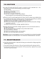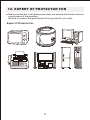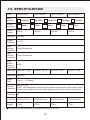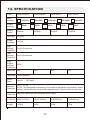
1
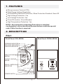
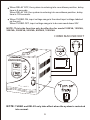
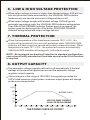
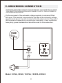
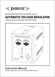
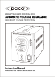
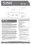
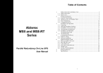
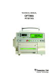
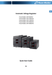
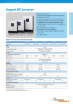
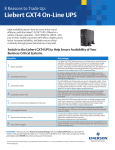
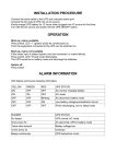
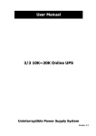
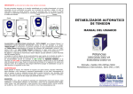
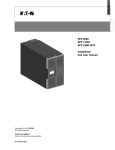
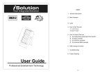
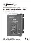
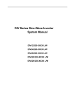
MICROPROCESSOR CONTROL (CPU)
AUTOMATIC VOLTAGE REGULATOR
HIGH & LOW VOLTAGE PROTECTION
AUTOMATIC VOLTAGE REGULATOR
Input Voltag e
Micropro cessor Control(
CPU)
High & Low Voltage
Protectio n
Outp ut Volta
ge
SW R-1000VA
Instruction Manual
Please read user manual carefully before use.
1. FEATURES
Microprocessor Control (CPU)
Wide Range Voltage Regulation
Automatically Executes Protection, When Protection Finished, Goes Off.
High Voltage Protection: Yes
Low Voltage Protection: Yes
Circuit Protection: Circuit Breaker
High Temperature Protection: Yes
NOTE: Not equipped overheating Protection in standard
configuration, users should notify manufacturer and take special
order if this function is required.
2. DESCRIPTION
FIG 1
Front Panel: 300-500VA
Rear Panel: 300VA-500VA
WORKING INDICATOR
DELAYING INDICATOR
UNUSUAL INDICATOR
AUTOMATIC VOLTAGE REGULATOR
INPUT VOLTAGE
METER
Input Voltage
Microproce ssor
Control(CP U)
High & Low Voltage
Protection
OUTPUT VOLTAGE
METER
Outpu t Voltag
Fuse
e
DELAY / UNDELAY
SELECTOR
Input
SWR-500VA
Output
POWER SWITCH
1
FIG 2
Rear Panel: 1000VA-2000VA
Front Panel: 1000VA-2000VA
WORKING INDICATOR
DELAYING INDICATOR
UNUSUAL INDICATOR
INPUT VOLTAGE
METER
AUTOMATIC VOLTAGE REGULATOR
Input Voltage
Microproces sor Control(CPU
)
High & Low Voltage
Protection
OUTPUT VOLTAGE
METER
Fuse
Output Voltage
INPUT VOLTAGE
TURBO SELECTOR
Input
SWR-1000VA
Output
DELAY / UNDELAY
SELECTOR
POWER SWITCH
FIG 3
Front Panel: 3000VA-5000VA
Rear Panel: 3000VA-5000VA
WORKING INDICATOR
DELAYING INDICATOR
UNUSUAL INDICATOR
INPUT VOLTAGE
METER
OUTPUT VOLTAGE
METER
AUTOMATIC VOLTAGE REGULATOR
Microprocess or Control(CPU)
High & Low Voltage Protection
Output
INPUT VOLTAGE
TURBO SELECTOR
DELAY / UNDELAY
SELECTOR
GND
SWR-5000VA
Output
Input
POWER SWITCH
2
FIG 4
Rear Panel: 8KVA-10KVA
Front Panel: 8KVA-10KVA
WORKING INDICATOR
DELAYING INDICATOR
UNUSUAL INDICATOR
INPUT VOLTAGE
METER
OUTPUT VOLTAGE
METER
AUTOMATIC VOLTAGE REGULATOR
Microproces sor Control(CPU
High & Low Voltage Protection)
INPUT VOLTAGE
TURBO SELECTOR
Input
DELAY / UNDELAY
SELECTOR
SWR-10KVA
POWER SWITCH
3
GND
Output
3. INDICATING SIGN
WORKING
WHEN THE GREEN INDICATOR IS LIGHTING. THE
REGULATOR IS WORKING.
WHEN ORANGE INDICATOR IS FLASHING EVERY
ONE SECOND, THE SYSTEM IS TURNING INTO
DELAYING STATE, AND THE REGULATOR HAS NO
OUTPUT. AFTER DELAY, ORANGE INDICATOR WILL
DELAYING
EXTINGUISH AND THE REGULATOR RESUME
OUTPUT.
UNUSUAL
WHEN OUTPUT VOLTAGE OF AVR IS HIGHER THAN
SET VALUE, THE SYSTEM ENTER INTO HIGH & LOW
VOLTAGE PROTECTION, UNUSUAL RED LED
FLASHES EVERY ONE SECOND AND OUTPUT GOES
OFF.WHEN OUTPUT VOLTAGE OF AVR IS UNDER
SET VALUE, THE SYSTEM ENTER NORMAL WORKING
STATE,UNUSUAL RED LED EXTINGUISHES.
WHEN TEMPERATURE OF AVR IS HIGHER THAN SET
TEMPERATURE, THE SYSTEM ENTER INTO
TEMPERATURE PROTECTION, UNUSUAL RED LED
FLASHES EVERY ONE SECOND AND OUTPUT GOES
OFF.WHEN TEMPERATURE OF AVR ARE LOWER THAN
SET TEMPERATURE, THE SYSTEM ENTER INTO
NORMAL WORKING STATE, UNUSUAL RED LED
EXTINGUISHES
NOTE: Indication for overheating is not equipped in
standard configuration. This function should be effective
only after users notify manufacturer in advance.
4
4. LED INDICATOR ILLUSTRATION
LED Indicator Illustration
CONDITION
WORKING-G DELAYING-Y UNUSUAL-R
Power Off
Working
Delay State
Output high voltage protection
Output low voltage protection
High temperature protection
NOTE:
: CONTINUOUSLY ILLUMINATE
: FLASH
: EXTINGUISH
NOTE: Indication for overheating is not equipped in standard
configuration. This function should be effective only after users
notify manufacturer in advance.
5. OPERATION
Before use, please make sure the voltage and power of the appliance
are accord with the labeled power and specification of the unit to avoid
any damage.
Please connect the appliance before turning on the unit. Switch on
appliance after you make sure the unit is working normally with output
voltage.
When connecting the electrical appliance with motor or compressor, such
as drill, air-conditioner and so on to the automatic voltage regulator,
please make sure that the power rating of the automatic voltage regulator
is at least 3 times of the power rating of the electrical appliance, so that it
can work smoothly, because the starting up power is much beyond of the
power rating of the electrical appliance.
5
When DELAY OFF, the system is entering into countdown position, delay
time is 6 seconds.
When DELAY ON, the system is entering into countdown position, delay
time is 120 seconds.
When TURBO ON, input voltage range is the rated input voltage labeled
on the unit.
When TURBO OFF, input voltage range is to be narrowed down 20V
NOTE: This turbo function only be effective for model 1000VA, 1500VA,
2000VA, 30000VA, 5000VA, 8000VA, 10000VA
HOME MAIN SOCKET
AUTOMATIC VOLTAGE REGULATOR
Input Voltage
Microproc essor Control(C
PU)
High & Low Voltage
Protection
Outpu t Voltag
e
SWR-1000VA
NOTE: TURBO and DELAY only take effect when the system is restarted
into normal.
6
6. LOW & HIGH VOLTAGE PROTECTION
When output voltage is lower or higher than labeled voltage, AVR will turn
into self-protection state automatically ,the UNUSUAL RED indicator
flashes every one second and output voltage will be cut off.
When output voltage comply with labeled voltage, AVR will go into
automatic recovering state, the UNUSUAL RED indicator extinguishes.
Then DELAYING ORANGE indicator flashes every one second, the
system goes into delaying state. After delay, DELAYING ORANGE
indicator extinguishes and output voltage resume .
7. THERMAL PROTECTION
When the temperature of the transformer exceeds 130℃+/-5% , the
system will automatically turn into self-protection state, UNUSUAL RED
indicator will flash every one second and output voltage shut down. While
temperature is lower 70℃+/-5% , the system will recover automatically.
UNUSUAL RED indicator will extinguish, and output resume.
NOTE: Not equipped overheating Protection in standard configuration,
users should notify manufacturer and take special order if this function
is required.
8. OUTPUT CAPACITY
The automatic voltage regulator will switch off automatically if the total
wattage of the electrical appliances exceed the automatic voltage
regulator output capacity.
If this voltage is in the range of 190-250V, the regulator provides the
100% listed maximum output power. maximum output power will change
as the curve shown below.
P(%)
100
OUTPUT: 220V~
75
50
USE THE SAME CURRENT
FUSE FOR REPLACEMENT
25
100
120
140
160
180
200
220
240
260
280
THE POWER CURVE OF OUTPUT
7
300 U(V)
9. GROUNDING CONNECTION
WARNING: BEFORE USING THIS AUTOMATIC VOLTAGE REGULATOR
YOU MUST PROVIDE A GROUND CONNECTION TO THE AUTOMATIC
VOLTAGE REGULATOR.
On the rear panel of the automatic voltage regulator is a terminal fitted
with a nut. This terminal is connected to the case of the automatic voltage
regulator and also to the earth terminal of the AC output socket. The use of
this terminal will depend on your particular installation. In any installation,
heavy duty, green-insulated wire should be used for this connection.
FUSE
Fuse
Input
Output
Model: 300VA, 500VA, 1000VA, 1500VA, 2000VA
8
In a stationary land based installation, the earth terminal should be
connected to a metal earthing stake driven into the ground to a depth of
1.2m or more.
Model: 3KVA, 5KVA
Output
Input
Output
GROUND TERMINAL
GND
Model: 8KVA, 10KVA
Input
GND
GROUND TERMINAL
Output
NOTE: The earth terminal of the AC outlet is connected to the neutral terminal.
This is the same as a standard household power point where the neutral line is
bonded to earth and there is normally no voltage between them.
9
10.CAUTION
In case of trouble with the AC output, e.g.short-circuit, overload, etc... the
protection circuit will automatically cut off the output.
In such cases:
(A) switch off the power at once
(B) disconnect all units
(C) check the connected devices
(D) use the unit again unless the problems
concerning the connected devices have been solved
When in use for a prolonged period of time, the AC output may suddenly be
cut off although the input voltage normal, This may be caused by excessive
temperatures. If this happens. Please proceed as follows:
(A) Switch off the automatic voltage regulator at once
(B) Disconnect some of the appliances or wait until the automatic voltage
regulator cools off
(C) Switch the automatic voltage regulator back on
Always keep the automatic voltage regulator in an environment which is:
(A) Well-ventilated
(B) Not exposed to direct sunlight or any other heat source
(C) Inaccessible to children
(D) Safe from water/moisture, oil or grease
(E) Safe from any flammable substance
WARNING: DO NOT DISASSEMBLE THE UNIT. HAZARDOUS VOLTAGE! DANGER!
PLEASE RETURN TO THE DEALER IF YOU FIND ANY PROBLEM WITH THE UNIT
11. MAINTENANCE
Very little maintenance is required to keep your automatic voltage regulator
operating properly.
You should clean the exterior of the unit periodically with a damp cloth to
prevent accumulation of dust and dirt. At the same time, tighten the screws
on the AC input terminals.
10
12. EXPERT OF PROTECTOR FOR
Make sure that the to tal laden power does not exceed the listed maximum
output power of the regulator.
Be sure to connect the ground point to the ground for your safty.
Expert of Protector For:
11
13. SPECIFICATION
P/No.
SWR-500VA
Input
Voltage
100-260V~
Output
Voltage
Output
Power
SWR-1000VA
220V ~
500VA
SWR-1500VA
120-260V ~
140-260V ~
230V ~
240V ~
SWR-2000VA
160-260V~
110V ~
80-140V~
115V ~
1000VA
1500VA
2000VA
250V AC,T8.0A
250V AC,T10A
250V AC,T15A
Frequency 50/60Hz
Output
Precision
+/-10%
High
Voltage
Circuit Protection
Protection
Low
Voltage
Circuit Protection
Protection
High
Output
255V~
Voltage
Protection
Input Fuse 250V AC,T5.0A
Fuse Size 5x20mm
Delay
Time
6 secs. / 120 secs.
130 O C +/-5%
Thermal
NOTE: Not equipped overheating Protection in standard configuration, users
Protection should notify manufacturer and take special order if this function is required.
Cooler Fan No
Dimension
(L x W x H) 24.5x11x16.5cm
26.5x15x18.8cm
26.5x15x18.8cm
26.5x15x18.8cm
Weight
4.7Kg
5.5Kg
6.7Kg
2.9Kg
specification are subjected to change without prior notice.
12
14. SPECIFICATION
P/No.
SWR-3000VA
Input
Voltage
100-260V~
Output
Voltage
Output
Power
SWR-5000VA
120-260V ~
140-260V ~
230V ~
240V ~
220V ~
3000VA
SWR-8KVA
SWR-10KVA
160-260V~
110V ~
80-140V~
115V ~
5000VA
8000VA
10000VA
25A
40A
50A
Frequency 50/60Hz
Output
Precision
+/-10%
High
Voltage
Circuit Protection
Protection
Low
Voltage
Circuit Protection
Protection
High
Output
255V~
Voltage
Protection
Input Fuse 16A
Fuse Size Circuit breaker
Delay
Time
6 secs. / 120 secs.
130 O C +/-5%
Thermal
NOTE: Not equipped overheating Protection in standard configuration, users
Protection should notify manufacturer and take special order if this function is required.
Cooler Fan Yes Auto-operation fan (temperature or load)
Dimension
(L x W x H) 39x21.5x26cm
39x21.5x26cm
47x28x36 cm
47x28x36 cm
Weight
16Kg
26Kg
31Kg
11.5Kg
specification are subjected to change without prior notice.
13
CAUTION
Avoid overloading
Do not use the regulator beyond its maximum power.
When connected to any appliance with built-in motor compressor, the
starting power is generally several times of the appliance's listed power
rating. Make sure that the total starting power capacity of all connected
appliance does not exceed the listed maximum output power of the
regulator. For color TV, calculate it twice as its listed capacity.
Make sure that the regulator is of the same output voltage and frequency
as the appliance's it connected.
Make sure that the voltage of electrical source is within the listed range
of the input voltage of the regulator.
Always place the regulator in an environment that is:
(A) Well ventilated.
(B) Not exposed to direct sunlight or heat source.
(C) Out of reach from children.
(D) Away from water moisture oil or grease.
(E) Away from any flammable substance.