1
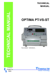
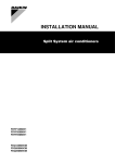
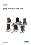
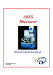
TECHNICAL MANUAL OPTIMA PT/ST/VS Page 2 NT1789 Rév.A0 TABLE OF CHANGES The information contained in this document only concerns : OPTIMA PT/ST/VS type, MCM 440 PT/OT type, MCM550 ST type. Technical Manual reference :......................... : NT 1789 Revision date :......................................... ...... : 27 May 2003 Applicable from serial no :.............................. : 18180100 Date 27/05/2003 NT1789 Rév.A0 Revision no. A0 Pages concerned All Changes First release page : 3 Page 4 NT1789 Rév.A0 TABLE OF CONTENT 1. OVERVIEW .................................................. 7 3.3.10. Display of software version number (TestA)......... 28 3.3.11. Motor clamp Test (TestC) .................................... 29 3.3.12. Calibration values display (TestE) ........................ 29 3.3.13. Infusion motor Test (TestF).................................. 30 3.3.14. Display of last 10 alarms before a failure occurs (TestJ) ............................................................................. 30 1.1. Ge n e ra l ......................................................7 3.4. Ma in te n a n c e S e rvic e Co n fig u ra tio n . ... 31 1.2. Blo c d ia g ra m s ...........................................8 1.3. P re c a u tio n s to b e ta ke n b e fo re u s e .......9 3.4.1. Service configuration Menu.................................... 31 3.4.2. Preventive maintenance (SAV1) ............................ 31 3.4.3. Set number Configuration (SAV2).......................... 31 1.4. In te rn a l s a fe ty fe a tu re s ............................9 3.5. Te c h n ic a l fa ilu re s m e s s a g e s . ............... 32 1.5. Te c h n ic a l c h a ra c te ris tic s ........................9 1.5.1. Biologica l cha ra cte ris tics .......................................... 9 1.5.2. Me cha nica l cha ra cte ris tics ....................................... 9 1.5.3. Dime ns ions / We ight................................................ 9 1.5.4. Ele ctrica l cha ra cte ris tics .......................................... 9 1.5.5. Ele ctronic cha ra cte ris tics ......................................... 9 1.5.6. Operator’s guide ...................................................... 9 1.5.7. Registration cards .................................................... 9 1.5.8. Material used to build the OPTIMA / MCM ............... 9 1.5.9. Conformity and -symbols ......................................... 9 2. ELECTRONIC BOARDS ............................. 11 2.1. CP U b o a rd ...............................................11 2.1.1. Functional description. ........................................... 11 2.1.2. Connectors description .......................................... 12 2.1.3. Electronic drawings ................................................ 14 2.1.4. Components layout ................................................ 14 2.2. Dis p la y b o a rd ..........................................15 2.2.1. Functional description ............................................ 15 2.2.2. Connector description ............................................ 15 2.2.3. Electronic drawings ................................................ 17 2.2.4. Components layout ................................................ 17 2.3. P OWER S UP P LY BOARD ......................18 2.3.1. Functional description ............................................ 18 2.3.2. Connector description ............................................ 18 2.3.3. Electronic drawings ................................................ 19 2.3.4. Components layout ................................................ 19 2.4. Air d e te c to r b o a rd ..................................19 2.4.1. Electronic drawings and Components layout.......... 19 3. Co n fig u ra tio n , c a lib ra tio n a n d c h e c k ....... 20 3.1. Co n fig u ra tio n ..........................................20 3.2. Ca lib ra tio n ...............................................22 3.2.1. Manual calibration menu ........................................ 22 3.2.2. Door calibration (Etal1) .......................................... 22 3.2.3. Correcting coefficient adjustment (Etal2)................ 23 3.2.4. Up and Down stream pressure sensors calibration (Etal9)..................................................................... 24 4. REP LACING S UB-AS S EMBLIES ................34 4.1. Mo d u le o p e n in g . .................................... 34 4.2. Re p la c in g CP U b o a rd . ........................... 34 4.3. Dis m o u n tin g p u m p in g m e c h a n is m ...... 34 4.4. Re p la c e m e n t o f p re s s u re s e n s o rs . ...... 34 4.5. Re p la c e m e n t o f d o o r o r o f Ha ll e ffe c t s e n s o r ............................................................ 34 5. MAINTENANCE ...........................................35 5.1. Re c o m m e n d a tio n s ................................. 35 5.2. Cle a n in g a n d d is in fe c tin g ..................... 35 5.3. S to ra g e .................................................... 35 5.4. Ro u tin e in s p e c tio n s .............................. 36 5.4.1. Checking before use .............................................. 36 5.4.2. Occlusion alarm checking ...................................... 36 5.4.3. Battery autonomy test ............................................ 37 5.4.4. Fix clamp checking ( VS/PT and ST pumps)......... 37 5.4.5. Air detector check .................................................. 37 5.4.6. Continuity test ........................................................ 37 5.5. Te c h n ic a l c h e c k p ro c e d u re .................. 38 6. ANNEXE 1 : Illu s tra te d p a rts lis ts ..............40 6.1. S u b a s s e m b lie s tra c e a b ility ta b le ......... 40 6.1.1. Introduction ............................................................ 40 6.1.2. Spare parts table.................................................... 40 6.1.3. Upper housing........................................................ 41 6.1.4. Base ...................................................................... 42 6.1.5. Brace ..................................................................... 43 7. Circ u it d ia g ra m ............................................45 8. Ad d e n d a a n d in fo rm a tio n b u lle tin s ..........46 9. Us e fu l a d d re s s e s ........................................48 3.3. Te s ts : Ma in te n a n c e te s ts .....................26 3.3.1. Manual Service test menu...................................... 26 3.3.2. Maintenance tests list : .......................................... 26 3.3.3. Working duration (Test1)........................................ 26 3.3.4. LED’s, LCD screen, 7 segments display and Buzzers Test (Test2) ............................................................ 27 3.3.5. Keyboard test (Test3)............................................. 27 3.3.6. Battery voltage display (Test4)............................... 27 3.3.7. Display of the last 10 alarms codes (Test5) ........... 28 3.3.8. Total working duration (Test6)................................ 28 3.3.9. Display analog values of sensors (Test9)............... 28 NT1789 Rév.A0 page : 5 P a ge 6 NT1789 Rév.A0 1. OVERVIEW 1.1. Ge n e ra l The OPTIMA Pump is a new volumetric pump based on the same mechanical pumping mechanism as the MVP pump. The battery is automatically recharged when the pump is connected to the mains.. A choice of easily accessible configurations ensures optimum use of functions according to the needs of each department. 3 types of OPTIMA exist : VS / PT/ ST • OPTIMA VS / MCM 440 OT: PVC Type Volumetric pump with standard PVC Set. The Drip sensors is optional. An automatic control of the occlusivity of the pump ( OCS –Occlusivity Control System) is implemented. • OPTIMA PT / MCM 440 PT :PVC Type Volumetric with standard PVC Set. The Drip sensors is compulsory. • OPTIMA ST / MCM 550 ST Silicone Type Volumetric with standard Silicone Set. The Drip sensors is compulsory • Mains differences between the types : Description VS / OT PT ST Functional differences Tube Standard PVC Standard PVC Standard Silicone Drip Sensor Optional Standard Standard OCS Test (Occlusivity Yes Control System) No No Tube Clamping A mechanical clamp on the device assure the clamping of the tube when the door is opened. A mechanical clamp on the device assure the clamping of the tube when the door is opened. A mechanical clamp on the device assure the clamping of the tube when the door is opened. Maximum Rate 1000 ml/h 1000 ml/h 1500 ml/h OCS A dc motor assure the NO OCS -> no DC motor clamping of the tube during OCS Tube clamping during A mechanical clamp on the device assure the clamping of the tube door opening when the door is opened. NT1789 Rév.A0 page : 7 1.2. Blo c d ia g ra m s Ba ttery RS 232 Nurs e Call Key board P owe r s upply board Dis pla y board conne ctors AIR bubble s Keyboa rd/dis pla y interface s e ns or Drip S ens or (option) CP U P roce s s or function DC Motor OCS (MS /VS only) Motor drive r S e ns or interface Motor Rota tion dete ctor Door Openning dete ctor Trans mis s ion P e ris taltic Me ca nis m DOOR L0OCK Counte r P res s ure fla s k downs tre am occlus ion Up-s trea m occlus ion De tector Detector Clamp dete ctor (MS only) Luer de rivation Down s tre am exte ns ion P UMP clamp Up-s tre am extens ion Drip chamber P erfus ion s et Figure 1. P a ge 8 Ge ne ra l dia gra m of the OP TIMA NT1789 Rév.A0 1.3. P re c a u tio n s to b e ta ke n b e fo re u s e Please consult the user guide. 1.4. In te rn a l s a fe ty fe a tu re s The pump has a continuous functions inspection system as soon as the pump is ON. . Nevertheless, the qualified personnel in your establishment or our Maintenance Department should always be notified of any abnormal functioning when no specific cause can be found. (See useful addresses, chapter 9) For any mains failure the pump is powered automatically from its internal battery. Opening the pump or the battery cover must only be carried out by qualified staff with all the necessary technical precautions. Non-compliance with these procedures may be dangerous for the staff and may damage the Module. 1.5. Te c h n ic a l c h a ra c te ris tic s 1.5.1. Biological characteristics The infusion liquid is only in contact with the infusion set. 1.5.2. Mechanical characteristics The OPTIMA Pump operates with a linear peristaltic system. 1.5.3. Dimensions / Weight q q H x L x D ........................................................................... 135 x 175 x 145 mm We ight ............................................................................... 2.9 kg a pproxima te ly 1.5.4. Electrical characteristics q q q q Exte rna l powe r s upply........................................................ 100 – 240 Vac Power ................................................................................. 50 VA Battery................................................................................ 6V – 2.7/ 3 Ah NiMH. Fuse ................................................................................... 2 x 630 mA T IEC 127 1.5.5. Electronic characteristics The Device contains 4 PCB’s: • CP U P CB. • Dis pla y / ke yboa rd P CB. • P owe r S upply P CB. • Air de te ction P CB 1.5.6. Operator’s guide The operator’s guide is available upon request to our Maintenance Department (see useful addresses at the end of this document) 1.5.7. Registration cards Registration information is available upon request to our Maintenance Department. 1.5.8. Material used to build the OPTIMA / MCM q q q q q q Top a nd bottom hous ing .................................................... P olyca rbona te / ABS Ke yboa rd ............................................................................ P olye s te r S ticke rs .............................................................................. P olye s te r P ump me mbra ne ............................................................... Ela s tome r (la te x fre e ) Drip s e ns or......................................................................... P olyca rbona te / ABS or polya mide Re a r hous ing ha ndle .......................................................... P C + 10% 1.5.9. Conformity and -symbols q Conform EN60 601-1 a nd EN60 601-2-24.s ta nda rds NT1789 Rév.A0 page : 9 CE0459 ma rking in complia nce with EEC 93/42 Me dica l De vice dire ctive . IP 31 Liquid proje ctions prote cte d. CF type de vice Ba tte ry. CLAS S I de vice q Ea ch s ymbol s hows be low is vis ible on the de vice or in this docume nt. Re fe r to a ccompa nie d docume nts . Equipote ntia lity P rote ctive e a rth 56 RS 232 Communica tion Inte rfa ce 4000V ins ula tion Nurs e Ca ll 4000V ins ula tion / 24Vdc-1A P e rma ne nt ma gne t a llowing the fixing of drops s e ns or P a ge 10 NT1789 Rév.A0 2. ELECTRONIC BOARDS 2.1. CP U b o a rd 2.1.1. Functional description. 2.1.1.1 CP U Ma in Microproce s s or .................. T80c5112 / 512 Ko of Fla s h / 8Ko of RAM Exte rna l RAM .............................. 32 Ko EEP ROM ..................................... 16 Ko S e conda ry Microproce s s or ......... MS P 430 Control fre que ncy of the ma in microproce s s or, time ke e pe r function, ON/OFF function a nd control the cha rge of the ba tte ry. 2.1.1.2 S te ppe r motor control The motor is powe re d with 12 or 20 volts a ccording to the flow ra te . The signal command is performed either by ½ step or ¼ step according to the requested flow rate. 2.1.1.3 Rota tion control An optical sensor verifies the rotation of the came shaft. This sensor generates an alarm for any difference higher than ± 5 % with the programmed value 2.1.1.4 Door de te ctor A Hall effect sensor placed in the Module and a magnet located in the door This sensor detects door opening and set missing when door is closed. 2.1.1.5 Drip s e ns or (optiona l on Optima MS a nd VS or MCM 440 OT) The drip detection is performed by an optical sensor. An infra-red filter avoids interference due to external light. This sensor generates an alarm for any flow rate difference higher than ± 40% of the programmed value 2.1.1.6 Downs tre a m pre s s ure s e ns or This sensor detects downstream occlusion on the infusion line. It also detects the right positioning of the infusion set when the door is closed. It generates an alarm in both cases. 2.1.1.7 Up-s tre a m pre s s ure s e ns or This sensor detects up-stream occlusion on the infusion line when the drip sensor is absent. This sensor detects the right positioning of the infusion set when the door is closed. It generates an alarm in both cases. 2.1.1.8 Buzze r The device is equipped with 2 buzzers triggered by the microprocessor. 2.1.1.9 On/Off function When the device is connected to the mains, it is in “stand by” mode . S witching ON is pe rforme d • Eithe r by pre s s ing the ON/OFF ke y • Or by ope ning the door, a ccording to the s oftwa re configura tion. S witching OFF is pe rforme d : • Eithe r ma nua lly by pre s s ing the ON/OFF ke y • Or a utoma tica lly whe n ba tte ry is low. The On/off function is pe rforme d by the s e conda ry microproce s s or 2.1.1.10 Ba tte ry cha rge ma na ge me nt NT1789 Rév.A0 page : 11 The ba tte ry cha rge is ma na ge d by both prima ry a nd s e conda ry microproce s s ors . 2.1.1.11 Air de te ctor An ultra - s ound s e ns or a llows to de te ct a ir bubble s in the infus ion s e t. It ge ne ra te s a n a la rm if a ir bubble s a re la rge r tha n progra mme d va lue . 2.1.1.12 Automa tic OCS cla mp The OP TIMA MS a nd VS or MCM MS a nd OT a re e quippe d with a DC motor a ctua te d cla mp. Afte r e a ch infus ion s ta rt or door clos ing, the infus ion s e t is cla mpe d by this s ys te m a nd the de vice che cks the n pumping me cha nis m occlus ivity. 2.1.1.13 Nurs e Ca ll / RS 232 The RS 232 a nd Nurs e Ca ll ha ve both 4000 V die le ctric s tre nght. The Nurs e ca ll re la y is ra te d 24 VDC/1A. 2.1.2. Connectors description 2.1.2.1 Ge ne ra l Co n n e c to r 2.1.2.2 2.1.2.3 P a ge 12 P in n u m b e r Fu n c tio n J7 2x17 For de ve lopme nt purpos e J3 2x7 For ma nufa cturing J9 1x4 Air S e ns or J1 1x20 CP U/Dis pla y inte rconne ction J 12 1x4 Drip S e ns or J4 1x4 S te ppe r Motor J6 1x3 P owe r S upply J8 1x4 Ba tte ry J5 1x6 Not Us e d J 11 1x8 RS 232 / NURS E CALL J 10 1x2 DC motor J2 1 x 20 J9 – Air Sensor S e ns ors P in De s c rip tio n 1 /TS T S e ns or che ck 2 5V P owe r S upply 3 GND Ground 4 /DETECT Air output s igna l J1 – CPU/Display board interconnection P in De s c rip tio n 1 2 3 4 5 6 7 8 9 10 11 12 5V VBAT GND MOS I-AFF GND MIS O_AFF GND CLK-AFF GND CS LCD GND CS AFCL P owe r S upply Ba tte ry volta ge S e ria l output S e ria l Input S e ria l clock Chip S e le ct LCD Chip S e le ct Dis pla y NT1789 Rév.A0 P in De s c rip tio n 13 14 15 16 17 18 19 20 2.1.2.4 Drip S e ns or GND A0AFF GND RES ET/ GND TON/OFF VBAT 5V P in De s c rip tio n 1 CDLED-goutte 2 GND 3 GND 4 P uls e -goutte 2.1.2.5 J 4 - S te ppe r motor 2.1.2.6 2.1.2.7 2.1.2.8 P in De s c rip tio n LCD Adre s s ON/OFF s igna l Ba tte ry Volta ge P owe r s upply Le d comma nd 5V / 40 mA Output drop s igna l 1 + Bobine A + Coil A 2 - Bobine A - Coil A 3 + Bobine B + Coil B 4 - Bobine B - Coil B J6 – Power Supply P in De s c rip tio n 1 ALIM EXT 2 GND 3 ALIM S ECT Not Us e d P owe r S upply 9V / 1.3A J8 Battery P in De s c rip tio n 1 VBATNC + Ba tte ry 2 ANA-CTN Te mpe ra ture s e ns or output 3 GND 4 VBATNP + Ba tte ry be fore the rma l fus e (fus e bre a kdown de te ction) J11 RS232/Nurse Call P in De s c rip tio n 1 TxD-P C Da ta Re ce ption from P C 2 RTS -P C Re que s t to s e nd from P C (S hould be pos itione d a t high s ta te ) 3 DTR-P C Da ta Te rmina l Re a dy of P C (S hould be pos itione d a t high s ta te ) 4 RXD-P C Da ta Tra ns mis s ion to P C 5 GND 6 Nurs e Ca ll Norma lly Ope ne d Conta ct 7 Nurs e Ca ll Common Conta ct NT1789 Rév.A0 page : 13 8 2.1.2.9 Nurce Ca ll Norma lly clos e d Conta ct J 10 - D.C. motor P in De s c rip tio n 1 + DC motor. 2 - DC motor. 2.1.2.10 J2 – Sensors P in De s c rip tio n 1 GND 2 P re s -Cla mp S witch cla mp output 3 CD-Cla mp S witch cla mp powe r s upply 4 Up-Force S e ns or Ups tre a m force s e ns or output 5 Up-Force S e ns or Upstream force sensor – input 6 Up-Force Sensor Upstream force sensor output 7 Up-Force Sensor Upstream force sensor + input 8 GND 9 Hall effect sensor Hall effect power supply 10 Hall effect sensor GND 11 Hall effect sensor Hall effect output 12 Dw-Force Sensor Downstream force sensor output 13 Dw-Force Sensor Downstream force sensor – input 14 Dw-Force Sensor Downstream force sensor output 15 Dw-Force Sensor Downstream force sensor + input 16 GND 17 ET-OPTO Outlet opto signal 18 CD-LED LED driver 19 GND Opto ground 20 5V LED Power supply 2.1.3. Electronic drawings On request at Fresenius Vial After Sales Service department 2.1.4. Components layout On request at Fresenius Vial After Sales Service department P a ge 14 NT1789 Rév.A0 2.2. Dis p la y b o a rd 2.2.1. Functional description The dis pla y boa rd is cons ide re d a s a pe riphe ra l boa rd of the CP U boa rd. • The ke yboa rd ma trix is conne cte d to this boa rd. • Dis pla y de s cription Fu n c tio n Dis p la y Flow ra te m/l 4 gre e n 7-s e gme nt LED dis pla y Ala rm 1 re d LED P re -a la rm 1 ora nge LED Perfusion signal LED’s 4 green LED Drop LED’s 1 green LED Battery LED’s 1 green LED Mains LED’s 1 orange LED Perfusion start LED’s 1 green LED LCD 33x100 points LCD display 2.2.2. Connector description 2.2.2.1 Ge ne ra l J1 1 x 20 Pins CPU/Display boards Interconnection J2 18 Pins LCD connector J3 10 Pins Keyboard connector NT1789 Rév.A0 page : 15 2.2.2.2 P a ge 16 J 1 - CP U/Dis pla y Boa rd inte rconne ction P in De s c rip tio n 1 2 3 4 5 6 7 8 9 10 11 12 13 14 15 16 17 18 19 20 5V VBAT GND MOS I-AFF GND MIS O_AFF GND CLK-AFF GND CS LCD GND CS AFCL GND A0AFF GND RES ET/ GND TON/OFF VBAT 5V P owe r S upply Ba tte ry volta ge S e ria l output S e ria l Input S e ria l clock Chip S e le ct LCD Chip S e le ct Dis pla y LCD Addre s s ON/OFF s igna l Ba tte ry Volta ge P owe r s upply NT1789 Rév.A0 2.2.2.3 J 2 LCD Conne ctor P in De s c rip tio n 1 VBAT + ba ck light 2 -le d - ba ck light 3 +5V 4 /RES ET 5 VS S Gnd 6 LD0 Da ta Write 7 GND Write S e le ct 8 LD6 Da ta Write 9 A0AFF LCD Addre s s 10 LD5 Da ta Write 11 LD4 Da ta Write 12 LD3 Da ta Write 13 LD2 Da ta Write 14 LD1 Da ta Write 15 LD0 Da ta Write 16 - Ena ble 17 LCDCS 2 Chip s e le ct 18 2.2.2.4 LCDCS 1 J 3 ke yboa rd Conne ctor Chip s e le ct P in De s c rip tio n 1 COL2 Ke yboa rd Column 2 COL1 Ke yboa rd Column 3 4 COL0 Ke yboa rd Column Ligne 3 Ke yboa rd Line 5 Ligne 2 Ke yboa rd Line 6 Ligne 1 Ke yboa rd Line 7 Ligne 0 Ke yboa rd Line 8 TON/OFF On / Off 9 CONTRÔLE Keyboard Control line 10 GND 2.2.3. Electronic drawings On request to Fresenius Vial After Sales Service department 2.2.4. Components layout On request to Fresenius Vial After Sales service department NT1789 Rév.A0 page : 17 2.3. P OWER S UP P LY BOARD 2.3.1. Functional description An AC / DC 12W Module convertor (switching mode power supply) convert the mains input voltage ( 100 – 240 Vac) to 9Vdc 1.3A. This voltage is used to charge the battery and power the device. ECG/EEG noise rejection filter : 2 Class X2 Capacitor and a 10Kohms resistance connected to a functional earth garanteed the EEG/EEG noise rejection 2.3.2. Connector description 2.3.2.1 Ge ne ra l Co n n e c to r 2.3.2.2 P a ge 18 P in Fu n c tio n J1 1x1 Functional Earth J2 1x2 Main supply connector J3 1x3 Output power supply J4 1x4 Battery Output J5 2x5 Battery Input J 1 Functiona l Ea rth P in De s c rip tio n 1 - Functional Earth NT1789 Rév.A0 2.3.2.3 J 2 Ma in S upply Conne ctor P in De s c rip tio n 1 PH Phase (100 – 240 Vac) 2 N Neutral (100 – 240 Vac) 2.3.2.4 J 3 Output P owe r s upply P in De s c rip tio n 1 9V Sect 2 GND 3 9V Ext 2.3.2.5 9V Output from AC/DC converter 9V From external power Supply (not used) J 4 Ba tte ry Output ( this conne ctor goe s to the CP U boa rd) P in De s c rip tio n 1 VBAT + Battery 2 + Capteur Temp Temperature Sensor output 3 Masse 4 VBAT NP GND + Battery before thermal fuse (fuse breakdown detection) 2.3.2.6 J 5 Ba tte ry Input ( this conne ctor come s from the ba tte ry pa ck) P in De s c rip tio n 1 VBAT 2 VBAT NP + Battery + Battery before thermal fuse (fuse breakdown detection) 3 + Capteur Temp Temperature Sensor output 4 - Capteur Temp Temperature Sensor GND 5 Masse Battery GND 2.3.3. Electronic drawings On request to Fresenius Vial After Sales Service department 2.3.4. Components layout On request to Fresenius Vial After Sales Service department 2.4. Air d e te c to r b o a rd The air sensor is based on an ultrasonic sensor. 2.4.1. Electronic drawings and Components layout The air sensor is based on an ultrasonic sensor. NT1789 Rév.A0 page : 19 3. Co n fig u ra tio n , c a lib ra tio n a n d c h e c k The configura tion a nd ca libra tion of the de vice a re a cce s s ible : ♦ us ing the s e ria l link (RS 232) a nd the Fre s e nius Via l P C s oftwa re to configure a nd ca libra te the pump. ♦ Us ing the ke yboa rd of the pump through a s pe cia l e ncode d me nu. For furthe r informa tion, ple a s e conta ct our Ma inte na nce De pa rtme nt (S e e a ddre s s e s a t the e nd of this docume nt) Any cha nge , in the configura tion le a ds to ma jor cha nge s in Module running, S ta ff tra ine d on the s oftwa re a nd de vice s a re the only pe ople a uthoris e d to pe rforme d the s e s ope ra tions . 3.1. Co n fig u ra tio n This mode is a ctive d by pre s s ing MODE ke y whe n s witching ON the pump/ The ma in me nu dis pla y : - Us e r s e tting - Wa rd s e tting - Ma inte na nce Each menu is composed with some sub-menu , press confirm key or “enter” to get through. Some menu need a code to access to the sub-menu The access code of “user setting” can be defined or disabled in the “ward setting”. Once the access code is typed it is not necessary to type it again as long as the device is not switched off. The 7 segments displays are off during the display of the main menu and codes typing. Ma in me nu Code Typing S ub-me nu S ub-me nu Ma in te n a n c e This code will be give n a t the e nd of the ma inte na nce s ta ff tra ining Te s t Ma inte na nce te s t me nu Ma in te n a n c e c o n fig u ra tio n Ma inte na nce configura tion me nu Ca lib ra tio n Ma inte na nce ca libra tion me nu Us e r s e ttin g ( see operator’s guide) Code XXXX User configuration menu Wa rd s e ttin g ( see operator’s guide) Code 0200 Service configuration menu P a ge 20 NT1789 Rév.A0 Test Ma inte na nce Configuration Etalonnage Calibration 7VW 7VW 7VW 7VW 7VW 7VW 7VW 7VW$ 7VW& 7VW( 7VW) 7VW6$9 6$9 (7$ (7$ (7$ Test1 Test2 Test3 Test4 Test5 Test6 Test9 TestA TestC TestE TestF TestJ SAV1 SAV2 Etal1 Etal2 Etal9 Work duration display LED’s, LCD screen, 7- segment displays and buzzers test. Keyboard test. Battery display Battery tension voltage display Last 10 alarms display. Total work duration display. Analog sensors value display. Software version number display. Clamp test.test. Clamp motor DC motor Calibration values display. Infusion stepper motor test. Before failure last 10 alarms codes display Preventive maintenance Tubing Set configuration Door calibration. Infusion correction coefficient configuration. Battery Up-stream and down-stream pressure sensors calibration. Ma in m e n u Us e r S e tting Wa rd S e tting Ma inte na nce Acce s s code type Us e r S e tting Code 0000 Ma inte na nce Code 0000 Wa rd S e tting Code 0000 Code s e le ction with S e le ction ke ys ( or ) P roce e d to s ub-me nus with c o n firm ke y or ENTER ke ys . Code ba ck to 0 if incorre ct code va lida tion, a fte r 15 s e conds non va lida tion = be e p. S TOP = ba ck to ma in me nu. Ma in te n a n c e s u b -m e n u Te s t Configura tion Ca libra tion NT1789 Rév.A0 page : 21 3.2. Ca lib ra tio n Ca lib ra tio n is p o s s ib le o n : • Down-s tre a m pre s s ure s e ns or. • Up-s tre a m pre s s ure s e ns or. • Door Ha ll e ffe ct s e ns or.. Ca lib ra tio n is c o m p u ls o ry in th e fo llo win g c a s e s • Down-s tre a m pre s s ure s e ns or : Afte r cha nge of s e ns or, of its prote ctive dia phra gm, of the door or CP U boa rd • Up-s tre a m pre s s ure s e ns or : Afte r cha nge of s e ns or, of its prote ctive dia phra gm, of the door or CP U boa rd • Door Ha ll e ffe ct s e ns or : Afte r cha nge of s e ns or, of the door or CP U boa rd q The CP U boa rd is configure d with s pe cific pa ra me te rs for e a ch De vice , s o it is forbidde n to cha nge CP U boa rds from a de vice to a n othe r. q For the s a me re a s ons , it is forbidde n to cha nge door from a de vice to a nothe r 3.2.1. Manual calibration menu S ELECTION ke ys = ca libra tion choice CONFIRM or ENTER ke ys = ca libra tion proce dure S TOP ke y = ba ck to ma inte na nce me nu. Va lue s a re not me moris e d. Ca libra tion numbe r is dis pla ye d on 7 s e gme nts dis pla y a nd s imulta ne ous ly dis pla ye d in inve rs e vide o on LCD s cre e n. (W$ Eta l1-Door Eta l2-Ra te Eta l9-P re s s ure Ca libra tions lis t : Eta l1 : door. Eta l2 : Infus ion corre cting coe fficie nt configura tion. Eta l9 : Up a nd Down-s tre a m pre s s ure s e ns or. 3.2.2. Door calibration (Etal1) q 3 le ve ls a re ca libra te d q Note : P re s s ing S TOP a llows to e s ca pe from the me nu without me moris a tion. q Door clos e d without s e t : (W$ Clos e the door without s e t, re cord the va lue by pre s s ing o n or q ENTER ke y. Door ope n without s e t : P a ge 22 NT1789 Rév.A0 (W$ Ope n the door without s e t, re cord the va lue by pre s s ing q on or ENTER ke y. Door clos e d with s e t : (W$ P la ce a s e t with the cla mp corre ctly pos itione d a nd clos e the door, re cord the va lue by pre s s ing or ENTER ke y. Va lue s : on Door clos e d without s e t : 1196 < X < 3750 mVolts Door ope ne d without s e t : 2197 < X < 2695 mVolts Door clos e d with s e t : 1699 < X < 3398 mVolts 3.2.3. Correcting coefficient adjustment (Etal2) This function a llows to a djus t the flow ra te of the de vice a ccording to the us e d s e t. The adjustment range allows a correction up to –20% +10% Measure the flow rate for a flow rate of 100 ml/h. Install the tube full with non mineral water, the container should be at 50cm above the device. Place a weight balance (0.01 g resolution and accuracy) at the same level as the device. Place a needle at the end of the tubing set. Collect on the balance the infused water. Select the rate and infuse for around 15 min. Press STOP on the device. Reset the balance (000g). Press START on the device (the pump infused at 100 ml/h). Infused for at least 15 min. Stop the infusion. Note the infused volume and time. Calculate the measured flow rate ( volume collected on the balance / infusion time) The Correcting coefficient adjustment is performed in Etal2. (7$ Selected 100ml/h Measured……..100ml/h (7$ Selected 100ml/h Measured……..105ml/h (7$ Selected 100ml/h Measured……..125ml/h Error S ELECTION key ( or ) : selects the programmed flowrate(100, increment 1 ml/h) and actual flow rate (80 à 120 ml/h). ENTER key : to select a field value. c o n firm ke y : ca lcula te re cord the ne w coe fficie nt if included between 0.8 and 1.1 times the programmed one, back to the configuration menu otherwise Error is displayed. NT1789 Rév.A0 page : 23 S TOP ke y : ba ck to the me nu without ca lcula tion of the coe fficie nt. Note : Afte r flowra te a djus tme nt a control of the flowra te s hould be done 3.2.4. Up and Down stream pressure sensors calibration (Etal9) This calibration should be done with the set selected on the pump in SAV2. sea §3.4.3, Set number Configuration (SAV2) The set has a relaxation time when the door is closed, so follow precisely the following procedure to guarantee the occlusion alarm level. Ba g 1m P UMP Ma nome te r 3 wa ys ta p 50 cm ta nk Te s t s e t The manometer and the device should be placed at the same level q Ca lib ra tio n RAZ Presure calibration NO Complete calibration choice YES or NO through the selection key . If Yes, the force sensor calibration values are set to zero for all the tubes YES choice is mandatory for any replacement of the force sensor door or CPU board NO choice does not set to zero the force sensor calibration value for the other tubes, only the one selected on the pump is set to zero. See §3.4.3, Set number Configuration (SAV2) The following procedure allows to carry out the calibration of the active tube. 3.2.4.1 Door ope n 1. Open the door of the device with o u t disposable set. 2. Record the values “ door open down-stream pressure” and “door open up-stream pressure by pressing on ENTER (W$ Values : door open down-stream pressure threshold : 1997 < X < 4453 mVolts 3.2.4.2 P a ge 24 door open up-stream pressure threshold : 1997 < X < 4297 mVolts Ca libra tion of the down-s tre a m pre s s ure s e ns or a t pre s s ure ze ro (0 mmHg), Door clos e d. NT1789 Rév.A0 1. Place a disposable infusion set as described here above and open the 3 ways tap between the pump and the manometer. 2. To relax the infusion set, press on the confirm key -> the pump run at 200 ml/h. 3. When the pressure reaches about 750 mmHg, open the 3 way tap to release the pressure. 4. Let infuse at zero pressure for about 5 minutes. 5. Stop the device by pressing on STOP. 6. Record the pressure by pressing ENTER; (W$ Va lue s : 3.2.4.3 down-s tre a m pre s s ure s e ns or a t pre s s ure ze ro (0 mmHg), Door clos e d : 1499 < X < 3696 mVolts Ca libra tion of the down s tre a m pre s s ure s e ns or a t 750 mmHg, Door clos e d; 1. Clos e the ta p be twe e n the pump a nd the ma nome te r. 2. S ta rt the pump by pre s s ing c o n firm ke y. 3. Ope n a nd clos e the ta p until the ma nome te r pre s s ure re a che s 750 mmHg ± 30 mmHg 4. Stop the pump by pressing on S TOP key. 5. Record the pressure by pressing on ENTER key. (W$ Values : down stream pressure sensor at 760 mmHg, Door closed 898 < X < 2998 mVolts 3.2.4.4 Ca libra tion of the up s tre a m pre s s ure s e ns or a t 0 mmHg 1. Open the tap between the pump, the manometer and tank. 2. Wait until the pressure set to zero. 3. Infusion set still in place and door closed, press ENTER key to record the value. (W$ Values : up stream pressure sensor at 0 mmHg 1499 < X < 3696 mVolts NT1789 Rév.A0 page : 25 3.3. Te s ts : Ma in te n a n c e te s ts 3.3.1. Manual Service test menu Choice with S ELECTION ke ys P roce e d with c o n firm or ENTER ke ys . Ba ck to ma inte na nce me nu with S TOP . (no pa ra me te r s tore d) Te s t numbe r is dis pla ye d on 7 s e gme nts dis pla y a nd s imulta ne ous ly on LCD s cre e n. 3.3.2. Maintenance tests list : Te s t1 : Dis pla y of working dura tion a nd numbe r of s witching on. Te s t2 : LED’s, LCD screen, 7 segments display and buzzers test. Test3 : Keyboard test . Test4 : Battery voltage display. Test5 : Last 10 alarms codes display. Test6 : Total working duration and total number of switching on. Test9 : Analog sensor value display. TestA: Software version number display. TestC : Clamp dc motor test. TestE : Calibration values display. Test F: Infusion motor test. TestJ : Last 10 alarms before fail codes display. 3.3.3. Working duration (Test1) Dis pla y the cumula te d pump working time in hours (<72 hours ) in da ys (<120 da ys ) or in months a nd the ma inte na nce da te . Fla s hing dis pla y &WUO, if pump working time is ≥ time be fore ma inte na nce (s e e S AV1) or if a ctua l da te ≥ ma inte na nce da te (S AV1). W6W ENTER : selects date S ELECTION : changes maintenance date in actual date or restores configured maintenance date. (if maintenance date = actual date then display = 0 h and Ctrl = erasing) Co n firm and ENTER : saves changes and goes back to test menu. S TOP : goes back to test menu with erasing of change of maintenance date. If date of maintenance is changed then working duration is set to zero. P a ge 26 NT1789 Rév.A0 3.3.4. LED’s, LCD screen, 7 segments display and Buzzers Test (Test2) Lighting of all the LED’s, display of plus decimal point on the 7 segments display, LCD screen completely black; wait for pressing on ON or ENTER. Scrolling of LED, one by one, scrolling of segments one by one on all the display then scrolling of and decimal point on each display. Scrolling of LCD screen image. Back to test menu (manual test). S TOP : quick return to test menu (manual test). 3.3.5. Keyboard test (Test3) W6W Display of pressed keys in inverse video. Co n firm or ENTER : back to test menu. 3.3.6. Battery voltage display (Test4) W6W W6W Co n firm o r ENTER : back to test menu. NT1789 Rév.A0 page : 27 3.3.7. Display of the last 10 alarms codes (Test5) W6W W6W S ELECTION : Code s s crolling. Co n firm or ENTER : ba ck to te s t me nu. 3.3.8. Total working duration (Test6) Display the Total pump working duration independent of Test 1. The Display duration can’t be set to zero. 3.3.9. Display analog values of sensors (Test9) W6W W6W Display of analog input values in form 0-5000 for 0-1024 Lsb. No display for up-stream sensor if not used. Co n firm or ENTER: back to test menu 3.3.10. Display of software version number (TestA) W6W$ W6W$ Co n firm or ENTER : proceeds to language version then back to test menu. S ELECTION : language scrolling. P a ge 28 NT1789 Rév.A0 3.3.11. Motor clamp Test (TestC) W6W& S ELECTION : function choice . Co n firm or ENTER : Run cla mp or uncla mp. S TOP : s tops motor a nd re turn to te s t me nu if motor a lre a dy s toppe d. Cla mp: the dc motor turns forwa rd to cla mp. Uncla mp : the dc motor turns ba ckwa rd to uncla mp. If problem on clamp motor driver then LCD screen black and “Er31” displayed on 7 segment display. S TOP : to return to test menu. 3.3.12. Calibration values display (TestE) W6W( S ELECTION : scrolling of calibration values. Co n firm or ENTER : back to test menu Display of calibration values in form 0-5000 for 0-1024 Lsb. The calibration values list is as following: Por1 : Hall effect sensor, door closed, without set. Por2 : Hall effect sensor, door opened. Por3 : Hall effect sensor maximum value , door closed, with set. Pam1 : Upstream pressure, door open. Pam2 : Upstream pressure, 0 mmHg. Pav1 : Downstream pressure, door open. Pav2 : Downstream pressure, 0 mmHg. Pav3 : Downstream pressure, 750 mmHg. The value between brackets gives the number of calibrations done. Display of upstream and downstream pressure calibration values in accordance with active set number. NT1789 Rév.A0 page : 29 3.3.13. Infusion motor Test (TestF) This te s t a llows to s e t the motor running without a la rm ma na ge me nt. W6W) S ELECTION : selection of infusion flow rate (0.1 ml/h à 1000 ml/h). ENTER : flow rate validation. S TOP : stops motor and return to test menu if motor already stopped If motor problem then LCD screen blank and “Er01, Er11, or Er21 ” displayed on 7 segment display. S TOP : to return to test menu. 3.3.14. Display of last 10 alarms before a failure occurs (TestJ) W6WW6WS ELECTION : scrolling number of switching on then error and codes. Co n firm or ENTER: back to test menu. P a ge 30 NT1789 Rév.A0 3.4. Ma in te n a n c e S e rvic e Co n fig u ra tio n . 3.4.1. Service configuration Menu. Dis pla y of configura tion numbe r on 7 s e gme nts dis pla y a nd coloure d inve rs e on the LCD s cre e n a t the s a me time . S ELECTION : configura tion s e le ction. Co n firm or ENTER: configura tion e xe cution. S TOP : re turn to te s t me nu. 6$9 S e rvice configura tions lis t : • S AV1 : pre ve ntive ma inte na nce . • S AV2 : s e t numbe r configura tion. Dis pla y of configura tion numbe r on 7 s e gme nts dis pla y a nd coloure d inve rs e on the LCD s cre e n a t the s a me time . 3.4.2. Preventive maintenance (SAV1) 6$9 S ELECTION : numbe r of hours be fore ma inte na nce or da te of ma inte na nce s e le ction. ENTER : cha nge s one fie ld to a nothe r. Co n firm : ba ck to S e rvice configura tion me nu with re cording of ne w dura tion a nd da te . S TOP : e ra s e s the la s t cha nge s a nd goe s ba ck to S e rvice configura tion me nu. Choice of numbe r of hours be fore ma inte na nce be twe e n 1 a nd 9999 hours . 0 inhibits the re que s t of pre ve ntive che ck with the working dura tion. Choice of the da te be twe e n 01/01/1990 a nd 31/12/2079. One of the thre e numbe rs = 0, inhibits the re que s t of pre ve ntive che ck with the da te . 3.4.3. Set number Configuration (SAV2) 6$9 Dis pla y of diffe re nt s e ts a va ila ble for the pump type . A che ck ma rk s hows the s e ts a lre a dy ca libra te d. S ELECTION : move s up or down in the s e t lis t. Co n firm or ENTER: s a ve s the s e t s e le ction (coloure d inve rs e s e le ction) S TOP : ca nce l the la s t s e le ction a nd re turn to ca libra tion me nu. If a non-ca libra te d s e t is s e le cte d, a t the ne xt s witching on, the de vice is locke d in occlus ion a nd/or ups tre a m pre s s ure a la rm, re quiring ca libra tion. NT1789 Rév.A0 page : 31 3.5. Te c h n ic a l fa ilu re s m e s s a g e s . Any te chnica l fa il us e initia te s a n e rror code a s we ll a s a continuous s ound a la rm. An e rror code is dis pla ye d on the 7 s e gme nts dis pla y. Erro r c o d e s 10 20 30 40 50 60 70 80 01 11 21 31 41 03 14 24 44 54 74 84 56 28 55 94 55 85 16 Err xx Ala rm c o d e s 10 12 16 17 18 19 20 21 P a ge 32 De s c rip tio n Inte rna l RAM proble m Exte rna l RAM proble m Incohe re nt EP ROM che ck s um EEP ROM proble m ADC proble m Incohe re nt infus ion s e t pa ra me te r Motor fre que ncy incompa tibility. Ke yboa rd proble m. Motor rota tion e rror. Motor rota tion e rror. Motor rota tion e rror. DC Motor. Motor rota tion e rror. S e ria l link tra ns mis s ion e rror Error on motor pe riod ca lcula tion pa ra me te rs ve rifica tion Motor rota ry dire ction incompa tibility. Qua rtz fre que ncy incompa tibility. dis pla y boa rd mis s ing. No ba tte ry conne ction. Ba tte ry cha rge e rror S oftwa re proble m. Non compa tible la ngua ge file . clock fa ilure Ba tte ry te mpe ra ture e rror S e conda ry microproce s s or e rror S e conda ry microproce s s or e rror Da te / time che ck e rror A xx De s c rip tio n Ba tte ry End of infus ion Downs tre a m Occlus ion Air de te ction Air de te ction Ups tre a m Occlus ion No tubing s e t No cla mp NT1789 Rév.A0 Ala rm c o d e s 22 23 24 25 26 27 NT1789 Rév.A0 A xx De s c rip tio n Door No drip s e ns or Drip s e ns or : low flowra te Drip s e ns or : high flowra te Fre e flow Occlus ion control page : 33 4. REP LACING S UB-AS S EMBLIES 4.1. Mo d u le o p e n in g . Whe n ope ning the OP TIMA, a nti-s ta tic pre ca utions mus t be s trictly a pplie d. The us e of a nti-s ta tic ca rpe t a nd grounde d bra ce le ts is highly re comme nde d. Dis conne ct ba tte ry a s s oon a s the Module is ope ne d. 4.2. Re p la c in g CP U b o a rd . In ca s e of CP U boa rd re pla ce me nt, s ys te ma tica lly pe rform configura tion a nd ca libra tion a s de s cribe d in cha pte r 3. 4.3. Dis m o u n tin g p u m p in g m e c h a n is m . Re tra ct the door a xis a nd re move the door. Re move the s ticke r up to the pumping me cha nis m to uns cre w a xis holde r. Uns cre w the 4 fixing s cre ws of the pumping me cha nis m. 4.4. Re p la c e m e n t o f p re s s u re s e n s o rs . In ca s e of re pla cing pre s s ure s e ns or, s ys te ma tica lly pe rform configura tions a nd ca libra tions de s cribe d in cha pte r 3. Be e xtre me ly ca re ful within the dire ction of the s e ns or pos itioning (le a d output). 4.5. Re p la c e m e n t o f d o o r o r o f Ha ll e ffe c t s e n s o r In ca s e of re pla cing the s e e le me nts , s ys te ma tica lly pe rform configura tions a nd ca libra tions de s cribe d in cha pte r 3 P a ge 34 NT1789 Rév.A0 5. MAINTENANCE 5.1. Re c o m m e n d a tio n s The qualified technicians in your establishment or our Maintenance Service should be notified of any abnormal operation of the device. For further information concerning troubleshooting or usage procedure, please contact our Maintenance Department or our Sales Representative. (see Useful Addresses, chapter 9) If the device has to be returned to our Maintenance Service, it must be disinfected and packed very carefully, if possible in its original packaging. FRESENIUS VIAL INFUSION SYSTEMS is not liable for loss or damage to the device during transport to our Maintenance Service. 5.2. Cle a n in g a n d d is in fe c tin g The Module DPS and the FRESENIUS VIAL Infusion Station form part of the patient’s immediate environment. It is advisable to clean and disinfect the device’s external surfaces on a daily basis in order to protect patient and staff. q q q Dis conne ct the FRES ENIUS VIAL OP TIMA P ump from the ma ins s upply be fore s ta rting to cle a n. Do not pla ce in a n AUTOCLAVE nor IMMERS E the de vice . Do not le t liquids e nte r the de vice ’s ca s ing. Us e a cloth s oa ke d in DETERGENT-DIS INFECTANT, pre vious ly dilute d with wa te r if re quire d. Avoid a bra s ive s crubbing which could s cra tch the ca s ing Do not rins e or wipe s urfa ce s . q q If the de vice is pla ce d in a high conta mina tion ris k unit, it is a dvis a ble to le a ve it in the room during fumiga tion dis infe cting, a fte r ha ving dis infe cte d it with a mois t cloth. Do not us e : À TRICHLOROETHYLENE-DICHLOROETHYLENE, À AMMONIA, À AMMONIUM CHLORIDE, À CHLORINE a nd AROMATIC HYDROCARBON, À ETHYLENE DICHLORIDE-METHYLENE CHLORIDE, CETONE These aggressive agents could damage the plastic parts and cause device malfunction. À q q Ta ke ca re a ls o with ALCOHOL BAS ED S P RAYS (20% - 40% a lcohol). The y le a d to ta rnis hing a nd s ma ll cra cks in the pla s tic, a nd do not provide the ne ce s s a ry cle a ning prior to dis infe cting. For furthe r de ta ils , conta ct the s e rvice in cha rge of cle a ning a nd dis infe cting products of your e s ta blis hme nt . 5.3. S to ra g e The device should be stored in a dry and cool place. In case of prolonged storage time, disconnect the battery through the battery door located on the rear panel . This operation should be made by qualified technician. When storage a full recharge of the battery is recommended before restarting the pump, in order to avoid any risk caused by micro mains supply cuts and to insure maximum autonomy. Storage place should be : Temperature between -10°c and 60°c Maximum relative humidity 90% no condensation. NT1789 Rév.A0 page : 35 5.4. Ro u tin e in s p e c tio n s 5.4.1. Checking before use (Refer to operating instructions) In order to ensure optimal work of the device, regular servicing inspections and tests are recommended. A servicing check procedure should include the points listed below. These service checks are not covered by any contract or agreement with FRESENIUS VIAL INFUSION SYSTEMS and are the responsibility of the User’s technical staff. For further information, please contact our Maintenance Service. q Note: Failure to comply with thes e maintenance procedures could damage the device and lead to a functional failure. 5.4.2. Occlusion alarm checking 1. Ma ke the following ins ta lla tion. 1m 50cm P UMP Ma nome ter bypa s s 2. P rogra m a 125 ml/h flow ra te a nd a counte r pre s s ure a la rm a t 500 mmHg. 3. S ta rt infus ion with bypa s s clos e d be twe e n ma nome te r a nd pump 4. Afte r 5 minute s of infus ion a t 0 pre s s ure , ope n bypa s s be twe e n the ma nome te r a nd the pump. 5. Whe n a la rm goe s , che ck the pre s s ure P dis pla ye d by the ma nome te r is corre ct : P = 500 mmHg ± 75 mmHg 6. Do the te s t a ga in with a progra mme d counte r pre s s ure of 750 mmHg. P = 750 mmHg ± 110 mmHg P a ge 36 -> 0.65 + 0.1 ba r -> 1 + 0.15 ba r NT1789 Rév.A0 5.4.3. Battery autonomy test 1. The battery autonomy is minimum 4h for usual flow rates (< 125 ml/h). 2. The battery(when properly charged) pre alarm gives a warning to the user about 30 minutes before total stop of the device. q Note : The ba tte ry cha rge dura tion is minimum 16 hours ( 100 % of its ca pa city) whe n the pump is ON. q Note : The ba tte ry cha rge dura tion is minimum 5 hours ( 100 % of its ca pa city) whe n the pump is off. 5.4.4. Fix clamp checking ( VS/PT and ST pumps) 1. Ma ke the following ins ta lla tion. Ma nome te r De vice Infus ion s e t P S yringe Drip cha mbe r 2. Ope n the door of the de vice , the in line me cha nica l cla mp s hould cla mp the infus ion s e t. 3. Apply a 0.5 ba r pre s s ure with the s yringe a nd che ck n o liq u id goe s in the drip cha mbe r. 5.4.5. Air detector check Note : Do the te s t with the tubing s e t dis pla ye d on the de vice . We re comme nd to do the te s t with the diffe re nts type s of tubing s e ts us e d in the hos tipa l. 1. P la ce a n infus ion s e t full of wa te r in the de vice . 2. For a n a ir bubble s volume progra mme d a t 0.20 ml. 3. P rogra m a 60 ml/h flow ra te . 4. Ge t drip cha mbe r ups ide down for a bout 20 s e conds ( to infus e a bout 0.5 ml a ir bubble ) 5. Che ck the a ir a la rm goe s whe n a ir bubble s pa s s through the a ir de te ctor. The le ngth pa s s ing through be fore a la rm s hould a pproxima te ly corre s pond to the s ize s e le cte d (1.3cm / 0.1ml). 5.4.6. Continuity test 1 Us ing a Ohmme te r, ve rify the pre s e nce of the e le ctrica l re s is tor highe r tha n 10 M ohms be twe e n Ne utra l a nd drip s e ns or plug (a ny pin) P ha s e a nd drip s e ns or (a ny pin) NT1789 Rév.A0 page : 37 5.5. Te c h n ic a l c h e c k p ro c e d u re In order to ensure follow-up within the framework of a preventive maintenance, a routine inspection is recommended. It is recommended to use the technical manual as a complement, for correct run of the procedure. A checking software allows to automatically perform the following tests. IMPORTANT : recharge battery ( 16 hours) prior to the check procedure De vice : OP TIMA / MCM Type : Check date : ........ / ........ / ........ Ch e c k N° Code : Device serial N° : Depart : Technician : Co n fo rm Description YES NO FUNCTIONAL CHECK ( see § 3.3.) 1 q Che ck ge ne ra l outs ide ca s ing a ppe a ra nce , ma ins powe r cord a nd s ticke rs . a nd pumping me mbra ne 2 q Dis pla y of working duration (test1) ………………………H/D/M 3 q Last maintenance date (test1) ………………………..D/M/Y 4 q Total working duration ( test 6) ………………………H/D/M 5 q Lights, buzzers and displays check (test2) 6 q Keyboard check (test 3 ) 7 q Door check Put on the pump without infusion set, door closed, connect drip sensor. Check the message on the alarm screen : Insert Tube Place an infusion set full of water in the device and closed the door: Check the absence of alarm. Open the door: Check the message : Door opened 8 OCS Te s t ( for pump OP TIMA MS a nd VS or MCM MS a nd OT) Ins ta ll a tubing s e t a nd put on the de vice Check that the OCS test passes correctly Clamp Check ( all pumps) Install a tubing set full of water (roller clamp opened) and bottle place at least 50 cm above the pump. Close the door and then open the door. Check the effective clamping of the tube (by the device for VS,PT,ST or by the clamp on the MS sets for the MS pump) :no drips at the end of the infusion sets. De te ction of the cla mp of the MS s e ts ( for MS type pumps ) Ins ta ll the MS s e ts prope rly in the pump. Turn on the MS pump Che ck tha t the re is no a la rm dis pla y Ope n the door a nd move the cla mp on the MS s e t outs ide the de vice . Clos e the door. Check that “no clamp”. P a ge 38 NT1789 Rév.A0 NA Ch e c k N° 9 Co n fo rm Description q YES NO Drip s e ns or che ck (if pre s e nt) Che ck s e ns or inte grity (chock ma rks , cle a nline s s of the de te ction zone , drip cha mbe r ma inta ining s pring, good condition of the cord) Conne ct the cord to the Module Ins ta ll a n infus ion s e t full of wa te r S ta rt infus ion Che ck tha t the gre e n indica tor fla s he s whe n a drop is de te cte d. Dis conne ct the s e ns or: Check that the “drip sensor “ alarm goes. ON Connect the drip detector , set the infusion at 60 ml/h remove the chamber from the drip detector . Verify the alarm should set : 40 sec < <2 min 30 sec 10 q Air bubbles sensor check (see 5.4.6) When switching on, without infusion set: Check that the red indicator and the air sensor of LCD display flash Install an infusion set full of water Check that the red indicator and the air sensor of LCD display switch off. Select a 60-ml/h flow rate and start infusion. Keep drip chamber up side down for, at least 20 sec. to generate a > 0.25 ml air bubble for a device configured for a cumulated air detection of 0.25 in 15 min. Check the alarm “air bubble” goe s on whe n bubble pa s s e s in the s e ns or. 11 q Down-s tre a m pre s s ure de te ctor. Install an infusion set full of water with a manometer at the end (see §5.4.2) Select a pressure threshold of 750 mmHg. Start infusion at 100 ml/h. Check that manometer indicates 750 mmHg ± 110 mmHg when alarm is triggered. Do it again for a pressure threshold of 500 mmHg (.± 75 mmHg) 12 13 Ave ra ge Flow ra te che ck (ca n a ls o be pe rform with a s ca le & IS De bit progra m te s t) P la ce the infus ion s e t in a 100ml te s t tube . S e le ct a 80ml/h flow ra te a nd infus e for 1 hour Note the infus e d volume The flow ra te ca n be a djus te d ( s e e 3.2.3) 76 ml < infused volume :……………………….ml< 84 ml q Ba tte ry che ck Before checking, charge the battery for at least 16 hours Start an infusion at 125 ml/h, m a in s d is c o n n e c te d Check working autonomy is > 4h IMP ORTANT : if autonomy < 3h30 , CHANGE battery. 14 q Continuity te s t Neutral and Drip sensor connector (any pin) > 10Mohms Phase and drip sensor connector (any pin) > 10 Mohms Earth and equipotentiality < 0.1 Ohms Earth and screw below the device < 0.1 Ohms Checking result conform no conform Visa : NT1789 Rév.A0 page : 39 NA 6. ANNEXE 1 : Illu s tra te d p a rts lis ts 6.1. S u b a s s e m b lie s tra c e a b ility ta b le 6.1.1. Introduction The aim of this chapter is to help the technician to find spare parts so that the module can be serviced. 6.1.2. Spare parts table The table below lists the mains modifications made to improve the product. The module’s serial number should be used when looking for components. OP TIMA / MCM e quiva le nce ta ble Ins trume nt s e ria l no. P a ge 40 1 From :18180100 To: Dis pla y boa rd 159602 CP U boa rd 159601 P owe r S upply boa rd 159603 NT1789 Rév.A0 6.1.3. Upper housing 100 101 102 103 104 105 106 107 108 109 110 111 112 Re fe re n c e 159611 159620 159602 159601 159646 168402 168403 168938 174252 168442 159899 NT1789 Rév.A0 Dig . re f 101 103 102 112 107 110 110 111 108 104 100 Qu a n tity 1 1 1 1 1 1 1 1 1 1 1 Co m p o n e n t Uppe r hous ing Ke yboa rd Dis pla y boa rd CP U boa rd OCS motor P T / VS / OT a ir bubble boa rd S T a ir bubble boa rd Air s e ns or OCS foa m ring Air s e ns or hous ing Drop de te ctor page : 41 6.1.4. Base 2 11 2 00 2 01 2 03 2 05 2 04 2 06 20 7 20 8 2 09 2 10 Re fe re n c e 159895 168480 168428 168439 651211 159621 168437 159604 159648 168479 168482 168483 168489 168485 159618 199261 199262 P a ge 42 Dig . Re f. 204 206 208 205 209 200 203 211 207 210 210 Qu a n tity 1 2 2 2 1 1 1 1 1 1 1 1 1 3 2 1 1 Co m p o n e n t Ba s e P re s s ure s e ns or S e ns or clip S e ns or me mbra ne Me cha nica l bloc me mbra ne Le ft hook Right hook Fla t ca ble Motor Me cha nica l bloc Be lt P ump s ide ge a r Motor s ide ge a r S ile nt bloc 40 s hore s Fe e t P T / VS / OT door kit S T door kit NT1789 Rév.A0 159632 1 S witch cla mp holde r 6.1.5. Brace 300 301 306 302 303 307 304 305 306 Re fe re n c e 159612 159613 159603 159622 159642 182108 159643 159617 NT1789 Rév.A0 Dig . Re f. 303 304 302 305 301 306 307 300 Qu a n tity 1 1 1 1 1 1 1 1 Co m p o n e n t Bra ce Optima S he lf Optima P owe r s upply boa rd Ba tte ry pa ck Nut S cre w ca p M8 s cre w Ha ndle page : 43 P a ge 44 NT1789 Rév.A0 7. Circ u it d ia g ra m Cicuit da igra ms a re a va ila ble ne a rby our s e rvice de pa rtme nt, ple a s e re fe r to us e ful a ddre s s e s cha pte r. NT1789 Rév.A0 page : 45 8. Ad d e n d a a n d in fo rm a tio n b u lle tin s P a ge 46 NT1789 Rév.A0 NT1789 Rév.A0 page : 47 9. Us e fu l a d d re s s e s All reques t for information or documentation (technical file, tubing catalogue or commercial documentation) s hould be addres s ed to : CUSTUMER SERVICE INTERNATIONAL Fre s e n iu s Via l Le Gra nd Che min, 38590 Brézins FRANCE Tel. : 33 (0)4 76 67 10 14 or 10 03 or 1067 Fax : 33 (0)4 76 67 11 12 E-ma il : comme rcia l.via l@fre s e nius he moca re .com MAINTENANCE SERVICES INTERNATIONAL Fre s e n iu s Via l Le Grand Chemin, 38590 Brézins FRANCE Tel. : 33 (0)4 76 67 10 76 Fax : 33 (0)4 76 67 11 22 BELGIUM Fre s e n iu s NV/S A Be lg iq u e DIVIS ION VIAL MEDICAL Molenberglei 7 2627 Schelle BELGIUM Tel. : 32/388.07307 Fax : 32/388.05007 GERMANY FRES ENIUS MCM AM-NEUNEN BERG 8 63749 ALZENAU GERMANY Tel. : 49/60 23 97 22-0 Fax : 49/60 23 43 06 It is pos s ible that this document contains typing errors or mis takes . Changes may occur at any time in s ubs equent editions . COPYRIGHT © 2002 Fresenius Vial This technical manual may not be reproduced in whole or in part without the written consent of Fresenius Vial Fresenius Vial SAS - Head Office: Le Grand Chemin - 38590 Brézins (FRANCE) Capital: 13,744,520 EUR - SIREN Grenoble B 408 720 282. P a ge 48 NT1789 Rév.A0