1
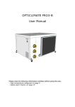
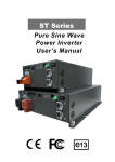
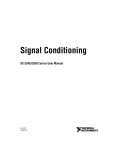
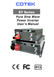
INSTRUCTIONS
OPTICLIMATE PRO3 SPLIT
Please take note of:
- High temperature protection on page 9
- Clear alarm history on page 15
1
Content
- Technical data / Specifications
3
- Installation
4
- Electrical connections
6
- Connecting the outdoor unit
10
- Commissioning
12
- Settings
17
- Inspection / Maintenance
21
- Failure analysis and error messages
22
- Error Code List
23
- Options, to be delivered with
24
- Appendix: Error code list
26
2
Specifications
OPTICLIMATE 3500 PRO3 SPLIT (WITH AIR-COOLED OUTDOOR UNIT)
Voltage
230V
Phase
Power
Cooling
Capacity
1 of 3
820W
3.5kW
No. Of Lamps
600W
400W
6
9
Heating
2 x 1500W
Dimensions
(mm)
870x580x405
Weight
50kg
OPTICLIMATE 6000 PRO3 SPLIT (WITH AIR-COOLED OUTDOOR UNIT)
Voltage
230V
Phase
Power
Cooling
Capacity
1 of 3
1590W
6kW
No. Of Lamps
600W
400W
10
15
Heating
3 x 1500W
Dimensions
(mm)
990x630x505
Weight
70kg
OPTICLIMATE 10000 PRO3 SPLIT (WITH AIR-COOLED OUTDOOR UNIT)
Voltage
230V
Phase
Power
Cooling
Capacity
1 of 3
2390W
10kW
No. Of Lamps
600W
400W
16
24
Heating
3 x 2000W
Dimensions
(mm)
1050x660x505
Weight
110kg
OPTICLIMATE 15000 PRO3 SPLIT (WITH AIR-COOLED OUTDOOR UNIT)
Voltage
400V
Phase
Power
Cooling
Capacity
3
3500W
15kW
No. Of Lamps
600W
400W
24
35
Heating
3 x 2700W
Dimensions
(mm)
1230x810x545
Weight
150kg
OPTICLIMATE 15000 PRO3 S SPLIT (WITH AIR-COOLED OUTDOOR UNIT)
Voltage
230V
Phase
Power
Cooling
Capacity
1 of 3
3500W
15kW
No. Of Lamps
600W
400W
24
The opticlimate 15000 Pro 3 Split is a Phase 1 Machine
Dimensions outdoor unit (mm);
-3500 Pro: 540x450x310
-6000 Pro: 640x550x320
-10000 Pro: 960x510x350
-15000 Pro: 1080x700x330
3
35
Heating
3 x 2700W
Dimensions
(mm)
1230x810x545
Weight
150kg
Installation
Fan mount (front / side)
If the unit is placed in a narrow space or in the ridge of a gable, place the fan outlet on the short
side of the unit.
This is done simply by rotating the purple panels shown in the picture so the fan panel is on to the
short side of the unit. This is done by rotating the red corner support 90o then upside down so there
are no loose cable connections.
At the rear of the unit where the carbon / particle filter is the air inlet must be a minimum distance of
15 cm from the wall in order to guarantee proper intake of the air. The distance between the top of
the unit and the ceiling should also be at least 15 cm. Greater distances are preferable. The unit
must be free of the walls to avoid unnecessary noises caused by contact.
4
The unit should be mounted so that the side of the condensation drain is sloping at least 1 cm lower
than the other side to make sure that the condensation flows out well. In practice, increases of 1 cm
on all angles, except for the corner of the electrical compartment, will enable the correct outcome.
The use of a spirit level is hereby advisable.
To avoid noises caused by vibration whilst in use, the OptiClimate comes with rubber mounts which
are suitable for pendant mounting.
For ground mounting or areas where it needs to be quiet you can remove the rubber mounts and
replace them with the isolator springs, which absorb more vibration. The unit will automatically fall to
the condensate drain.
Rubber Mounts
5
Isolator Spring Mounts
Electrical Connections
Humidistat, Remote terminal,
Outdoor unit, Temperature sensors
Power supply
In order to make the various electrical connections they have to be to the left of the panel, the first
manometer dismantled.
Included is a 5-core cable, humidistat, remote and room temperature. The wiring of this can be fed
through the opening at the bottom of the panel. The power cable for the power supply to the side is
led by the black rubber grommet.
Alarm Output
On the PCB is an alarm output, it is activated (contacts) when a fault (error) is detected. This output
can be used with a mobile phone detector or connected to an alarm system. The output can be set
to NO or NC via the Settings menu. This means that the contact is opened or closed by a
notification. See the manual of the mobile phone detector or alarm.
Alarm Output
Sensor dual room
Humidistat with light cell
The humidistat supplied with built-in light sensor is already connected. The cable must to be guided
through the opening in the panel only, The unit should be suspended in space and The light cell in
the humidistat
must not be covered. OptiClimate automatically switches from day to night mode.
6
Room Temperature
The compartment is also the room temperature. This is already connected to the PCB. The sensor is
used by the opening in the panel through to the outside and is to be to be hung in line with the top
of the crop. The sensor must be protected against heat radiation but not placed in the shade, a
cover on top of the sensor is sufficient.
The Remote
The remote can also be hung in the
compartment is in space but also elsewhere.
OptiClimate can also operate outside the room.
The four core cable is already connected, and
entered by the opening in the panel, to be
carried out.
5-Core Cable
Included is a 5-pin connector to provide power to the outdoor unit and to connect the indoor unit.
The temperature in the outdoor unit is connected by the 5-core cable to the terminal strip in the
indoor unit and the white junction box to the outdoor unit. The 5-core cable must be passed through
the opening in the panel and is connected to the indoor unit as follows.
Blue (or black with # 1 *) N
Brown (or black with nr2 *) 7
Yellow / green PE
Black or gray (or black with # 3 *) 24
Black or gray (or black with # 4 *) 23
* (depending on the type of 5-core cable included)
Power cables
There are five different OptiClimate models. For your safety and the safety of the OptiClimate serve
to connect the power supply, the following specifications are to be observed; Use the specified
circuit breakers and cable sizes
Model
Circuit breaker
Cable sections
3500pro3
first phase D16 automatic
2.5 mm2 cable
3500pro3
3 phase automatic D10
2.5 mm2 cable
6000pro3
first phase D25 automatic
4.0 mm2 cable
6000pro3
3 phase automatic D16
2.5 mm2 cable
10000pro3
first phase D35 automatic
4.0 mm2 cable
10000pro3
3 phase automatic D20
2.5 mm2 cable
15000pro3 (S) 1 phase D50 automatic
6.0 mm2 cable
15000pro3 (S) 3 phase automatic D35
4.0 mm2 cable
15000pro3
4.0 mm2 cable *
3 phase automatic D25
* This unit is the compressor divided over 3 phases
7
The cables for the power supply must be guided through the grommet on the side to be connected
to the left side of the terminal strip as described in the figure. The earth can be connected to
terminal PE or on the screw on the metal casing directly below the terminal block.
D3500pro, D6000pro & D1000pro 230 (1 & 3 phase). At phase 1, 2 loops between L1-L2 and
L2-L3 of the heating elements. 3-phase is always preferred.
Connections to the
terminal strip left corner
Connections to the
terminal strip right corner
230V 3 phase
Humidistat
2 loops 230V 1 phase
Temperature
protection
Outdoor fan unit
Outdoor
temperature unit
Wiring diagram for the pro D15000 400v 3 phase only
Connections to the
terminal strip left corner
Connections to the terminal strip
below right corner
430V 3 phase
Temperature
protection
Outdoor fan unit
Humidistat
8
Outdoor
temperature unit
High temperature protection
If the temperature in a room is too high OptiClimate switches the heat sources (eg lamps) off. In the
unit there is a connection that can be connected to the timer on the switchboard.
The power wire runs to the switch on the switchboard should this be interrupted. In one example, this
is Grasslin clock terminal 1 and at a LeGrand switch this connection 4 is scheduled for D15000 pro
400v 3 phase only.
The two ends must be at terminal 15 & 16 on the connected terminal strip in the OptiClimates
electrical compartment.
The power for the switch then runs through the OptiClimate. If the temperature is above 35 ° C, the
OptiClimate interrupts the circuit so that the heat sources switch off. ERROR 15 will appear on the
remote.
Always refer to the instructions of the manufacturer of the switch if another model is used than what is
shown is this example.
9
Connecting the Outdoor Unit
Placing the outdoor unit
The outdoor unit should preferably be placed outdoors in a cool place (Shadow) to which the unit
can suck dirt. When mounted, enough space should be left around the unit to ensure proper supply
of air. If the air by the outdoor unit is warmer, then the capacity is reduced (table) if the ambient air
above 40 ° C, creates an error E: 16. The unit continues to operate as normal.
Connecting coolant hoses
Included are 2 coolant hoses. One hose has a large diameter and the indoor unit connected to the
"steam" (above). The other hose has a slightly smaller diameter, and is connected to the "liquid"
(below).
On the outdoor unit, the hose with the largest diameter is connected to the upper and the hose with
the smaller diameter is connected to the lower connector.
Caution! Coolant hoses must not be kinked or at an acute angle when mounted. The hoses must not
be shortened or extended.
The connection on both the indoor and outdoor unit must first be rotated by hand. Hereafter
connections with two wrenches can be tightened, not tighten too hard if connecting 5 core cable
to the outdoor unit.
The outdoor unit is a white waterproof junction box. 5, the wire cable extending from the
indoor unit must be connected herein.
Blue on blue or black No. 1 *
Yellow / green yellow / green
Brown on brown or black No. 2 *
Black or gray on black or black No. 3 *
Black or gray on black or black No. 4 *
* (Depending on the type of 5-core cable included)
Condensation drain
During cooling, the unit also dehumidifies the air; the fluids from the air are drawn out of the
condensation drain. The condensation drain is connected to a sturdy garden hose or tubing that is
not easy to bend. The condensation dripping out of the hose can be connected to the drain. The
condensation can also be used as feed water. The heatsink is adjusted so that no metal or
oxides may end up in the condensation water. This is ideal if only hard water is available as a water
supply.
10
The condensate drain must not have loops and should be placed into a barrel but not go under the water
level.
When the unit is placed equal or lower than the drain or sewer, water can be picked up by a
condensation delivery pump. This small lift pump is pumping up to 4 meters through a tube of 9 mm
to the drain. There are stronger pumps available if needed.
Condensation Drain Pump
Faulty Discharge
The outlet to the pump must not be under water and have no loops examples are as shown above.
The unit is now installed and can be put into use
11
Commissioning
Operation
↑
=
Temp up / scroll
↓
=
Temp down / scroll
T
=
Press to set time / Press and hold to confirm
FN
=
Fan speed
S
=
Press to read Sensors / Press and hold is Menu
R
=
Press to confirm / Press and hold to erase / delete error codes
M
=
Pressing M switches between day and night mode manually. Pressing and
holding M turns automatic light sensor mode on / off.
On / Off
=
Unit On / Off or confirm menu option.
1) On / Off button
The On / Off button turns the unit on and off. If the unit is turned on, the LED lights green. If the unit is
off the LED lights red. When a fault is detected the LED will flash red / green. The On / Off button is
also used to confirm a menu selection.
2) Mode button 【M】
Pressing the mode button switches between day mode (cooling) and the night mode (heating /
dehumidification). In the day mode a snowflake is pictured in the display with night mode a sun with
water drops is shown.
Night mode
In the default mode, the temperatures are already be set for day and night.
This can be changed later.
12
3) Fan speed button 【Fn】
This is used for the selection of the air speed of the fan, the sequence is:
Automatic
Low
Medium
High
The speed changes each time the Fn key is pressed.
If the automatic ventilation mode is selected in the cooling mode, the unit will
go up or down depending on the ventilation cooling requirements.
4) Temperature setting
Users can set the temperature from 16 ℃ to 34 ℃ when the ▲ or ▼ button is pressed, the SET TEMP
temperature setting will be displayed on the display, when pressed again. Here the user can set the
desired temperature. To confirm setting press and hold. After 3 seconds, the setting will be saved.
Use【M】mode button to switch between day and night.
5) Time setting 【T】 key
Press the 【T】 button to select the hours and now press the ▲ or ▼ button to change the hours.
Press 【T】 button again start flashing the minutes, and now press the ▲ or ▼ button to change the
minutes. Now press 【R】 key to confirm the entry.
6) Automatic Brightness sensor setting (Day / Night Mode)
In the humidistat of the pro3 is a light cell. This shows when the light is on, in light it switches to day
mode and no light to night mode. Only the Day / Night temperatures should be set, the rest is easy.
If you still want to set the unit manually the automatic light sensor can be disabled, by pressing the
【M】 mode button for 3 seconds.
This mode alternates between light emitter and manually. By pressing the【M】button another 3
seconds the mode goes back to the emitter mode. If the automatic light cell is activated, there will
be a big A shown in the display panel.
It is important to note that when the timer setting is programmed, the automatic light sensor mode is
deactivated. So only install a timer when in use and use advanced options to configure.
The Timer mode is active when a clock symbol is on the display.
The external unit should be connected to the light sensor on the terminal block in the electrical
compartment (terminal 12, 14 and 18) otherwise the unit will remain in night mode because no light
is detected. This is the standard connection.
13
7) Timer setting (DAY / NIGHT program)
By default, we recommend to use the timer, automatic light sensor mode
So only set if you want it to work without light cell.
This function can be used for the DAY / NIGHT program. This program restarts, every day no matter
what day it is. The timer is set, when the display shows the clock symbol.
Press 【T】 key for 2 seconds, when "---", ON is visible, the user can set the timer
To change setting. Pressing ▲ or ▼ on the hours the ON time can be set by pressing 【T】again the
minutes can be set. The ON time is the time that the unit is cool.
When 【T】is pressed again the OFF time can be set. The OFF time is time the unit is heating /
dehumidification.
The display will show "-: -" If there is no timer set, or else the time that is already set.
Example:
The unit must cool down between 8:00 and 20:00.
The ON time should be set to at 8:00 AM
OFF time must be set to 8:00 PM
1:00 AM = 1:00
1:00 PM = 13:00
2:00 AM = 2:00
2:00 PM = 14:00
3:00 AM = 3:00
3:00 PM =15:00
4:00 AM = 4:00
4:00 PM =16:00
5:00 AM = 5:00
5:00 PM =17:00
6:00 AM = 6:00
6:00 PM = 18:00
7:00 AM = 7:00
7:00 PM = 19:00
8:00 AM = 8:00
8:00 PM = 20:00
9:00 AM = 9:00
9:00 PM = 21:00
10:00 AM = 10:00
10:00 PM = 22:00
11:00 AM = 11:00
11:00 PM = 23:00
12:00 PM = 12:00
12:00 PM = 24:00
To delete the time during the timer setting (turning off of the timer)
Press 【R】 key, and the time is erased. The display will show "-: -" display.
EXIT: Press 【T】key 3 times to exit or wait 10s to close automatically.
The settings must run synchronously with of the current time and timer settings with the times on the
switchboard. All clocks must be synchronized when the timer function is used.
14
8) Using of the humidistat to dehumidify at night
The humidistat can be set to the desired maximum humidity for night time. When the night mode is
active and the humidistat indicates that the unit must dehumidify the drop symbol will flash. During
dehumidification it will also need to use water.
Humidistat
9) Readout function for temperature sensors
Press the【S】 key and the sensor temperature is displayed. The number and the temperature of the
sensors is displayed in place of the clock.
By pressing the ▲ and ▼ keys users can choose different sensors to read.
EXIT: Press 【S】 key to exit or wait 60s for the option to automatically close.
C: 01 = heatsink temperature
C: 02 = temperature refrigerant from outdoor unit (liquid / return)
C: 03 = room temperature 2 (only for dual-room configuration, now-40g)
C: 04 = temperature (cold) air blown
C: 05 = temperature (warm) air drawn
C: 06 = temperature low pressure (for compressor)
C: 07 = Outside air temperature (for outdoor unit)
10) Readout function for the error codes
If the On / Off LED is flashing green / red flashing this indicates a fault. The actual error code will
be shown with E: XX. If the problem resolves itself, the error will disappear.
Below the display remote control is the error log (alarm history). If there has been an error, the error
will be visible on the bottom of the display, even when the error has been resolved.
In this way, an emerging malfunction or incorrect adjustment can be noticed early and / or
corrected.
Clearing the error log (alarm history)
Errors in the log can be cleared by pressing the (R) button as they are resolved press and hold.
Making good use of the alarm history items means any problems can be better detected and
resolved early!
15
12) Alarm output
On the PCB is an alarm output which makes contact with an alarm when an error has occurred, at
this
contact a detector can be connected to alert an alarm system or SMS (GSM).
13) Compressor operating mode
If the compressor is running, the compressor symbol will be displayed right below on the display, in
turn this will disappear.
The compressor operates only in the day-time as the temperature is exceeded and in the night-time
when the relative humidity set is exceeded.
14) Heaters active mode
If the heaters are turned on the hot air symbol below will be shown on the display, in turn this will
disappear.
The heaters operate only at night-time when the temperature is below the set value.
15) Fan outdoor unit operates.
When this symbol appears on the display, the fan (s) on the outdoor unit are turned on.
When switching off, the fan (s) symbol will disappear. The fan (s) on the outdoor unit will only run
when needed.
16
Settings (Setup)
In this menu you can change certain settings, adjust the heating, temperature protection, auto
restart and hysteresis setting.
Press and hold the【S】button for longer than 6 seconds to access the settings menu. A capital letter
D appears on the screen followed by a number from 01 to 29. Press the【S】key again briefly
pressing repeatedly run through the different settings.
The first setting is D: 01 second D: 02, etc.
To change a setting, you do so with the ▲ or ▼ button. To confirm this
press the 【ON / OFF】 key. If you want to change anything and exit the menu, press
press the 【R】 key.
The settings range from D 01 to D 32.
If you want to reset to factory settings press the【M】button while you are in the settings menu. All
settings are now defaulted back to factory settings. Confirm by pressing the on / off button.
D: 01 Heaters on / off
There are three heating elements in the OptiClimate. There are 1-phase systems in all three
connected to the first phase and at a 3 phase distributed over the 3 stages.
In the Settings menu, each of these elements can be turned on and also disabled. They can also all
be shut off when, for example, central heating is on.
Setting:
D: 1 = 3 means all three elements will heat
D: 1 = 2 means two elements will heat
D: 1 = 1 means the first element will heat
D: 1 = 0 means all the elements are off
D: 02 Temperature protection
If the room temperature is above 35 ° C, the unit via the terminals 15 and 16 will turn off the heat
source to the terminal strip. By setting D: 02 you may change the cut out to act between 30 ° C and
40 ° C. If the temperature drops below the set temperature, the cooling mode will disable security
again.
The security has no influence on the operation of the OptiClimate. However, there will be an error
message given, ie E: 15. (See also the error code list)
D: 03 Auto restart after power failure
If the voltage is interrupted when the unit is turned on, the voltage will return the unit to default
setting to allow it turn back on safely.
If after a power failure you want the unit to remain off; or when it is assumed an interruption has
occurred by external interference, connect the D setting: change to D 03.
Setting:
D: 03 = 0 means auto restart is off.
D: 03 = 1 means auto restart is on.
This is the default setting. There will always be an error code displayed when a power failure has
occurred, i.e. code 14. See also error code list.
17
D: 04 Night cooling (Cool at Night) on / off.
In this parameter, the night cooling can be changed.
D: 04 = 0 means cool at night is out. This is the default setting.
D: 04 = 1 means cool at night is on.
If the timer off mode is on, and the minimum temperature is set to e.g. 22 ℃, the unit will
cool the room at 22 ℃ in night mode. If the temperature is below 22 ℃ the unit will heat up.
In a warm climate, a very well insulated space or other heat sources cannot be deactivated this
function is required to maintain accurate levels.
If the cool at night function is active there will be a moon visible in the display.
D: 05 Heater (Pre-Heat) on / off.
In this parameter, the heating can be turned on.
D: 05 = 0 means pre-heat is off. This is the default setting.
D: 05 = 1 means pre-heat is on.
If pre-heat is activated, the room will heat up for an hour during the day (on timer) the space will
warm up to the set cooling mode (day) temperature. The space is then at the correct temperature
at immediately at the start of each day. Apart from the advantage of the temperature one day
needing a jump-start, this also prevents cold parts which will reduce and prevent mould.
Note: Only works in conjunction with the timer and not in the light cell mode!
D: 06 After heating (slow cool-down) on / off.
In this parameter, the post-heating can be switched on.
D: 06 = 0 means slow cool-down is out. This is the default setting.
D: 06 = 1 means slow cool-down is on.
In slow cool down on, the heating may reduce gradually rather than shut down completely until one
hour after the day has ended to ensure the room cools slowly.
Note: Only works in conjunction with the timer and not in the light cell mode!
D: 07 2 bedrooms 12/12 cooling (dual room) on / off.
In this parameter, the 2 cooling chambers can be turned on.
D: 07 = 0 means dual operation room is off. This is the default setting.
D: 07 = 1 means dual operation room is on. If this function is active, the display shall include the
cottage visible on the screen.
To use this function, there must be a three-way valve and connection ordered to be composed of;
3-way valve, plenum, 2nd temperature sensor and an extensive installation manual / instructions.
D: 08 Alarm output N.Ö. or N.C.
In this parameter, the alarm output can be adjusted.
D: 08 = 0 means N.C. Normally closed. This is the default setting.
D: 08 = 1 means N.Ö. Normally open.
For the correct setting to connect; the user should consult the GSM detector or alarm.
18
D: 09. Not applicable
D: 10 Timer output
At D: 10 = 0 will output 15 and 16, the interruption of the high temp alarm.
At D: 10 = 1 high temp alarm will not go through these contacts.
At D: 10 = 1 will be 16 common, and 16 & 17 each changeover contacts.
The clock of the OC shall now operate changeover contact and the clock on the switchboard can
be substituted for the clock / timer in the OC. The lights then run synchronously with the cooling
mode of the OC.
Now a high temp to post security must contact 16 are placed in line the alarm output on the PCB.
If there is a high temp alarm will signal, pause the timer and updates the temp security.
The setting of the alarm output must then NC (default 0) position.
D: 11 of the hysteresis temperature
In this setting, the hysteresis (bandwidth) of the temperature control can be
adjusted. This is the temperature difference which is required to switch the compressor on and off.
Setting:
D: 11 = 2 means the hysteresis is 2. This is the default setting.
The hysteresis can be set from 1 to 4 ℃ in increments of 0.5 ℃. If the set daytime temperature is set to
e.g. 28 ℃ and the hysteresis at 2 ℃, the unit will begin cooling at 29 ℃ and stop cooling at 27 ℃. To
hysteresis actually works to shorten the compressor. (D:27)
D: 12 Not less than the adjustable preheat temperature
With this option, the minimum controllable heating temperature can be changed.
The adjustable values in D: 12 standard = 16 ℃, max = 20 ℃, min = 10 ℃.
D: 13 Not more than the selectable preheat temperature
With this option, the maximum adjustable heating temperature can be changed.
The adjustable values in D: 13 standard = 35 ℃, max = 50 ℃, min = 25 ℃.
D: 14 The least adjustable cooling temperature
With this option, adjustable minimum cooling temperature can be changed.
The adjustable values in D: 14 standard = 16 ℃, max = 20 ℃, min = 10 ℃.
D: 15 Maximum adjustable cooling temperature
With this option, the maximum cooling temperature can be changed.
The adjustable values in D: 15 standard 35 ℃, max = 35 ℃, min = 25 ℃.
D: 16 Not applicable.
D: 17 Heat sink anti-freeze protection
This option can be determined at which temperature the cooling block anti-freeze alarm
is activated. The settings in D: 17, default = 0 ℃, max = 5 ℃, min = -2 ℃.
D: 18 Not applicable.
D: 19 Not applicable.
D: 20 Not applicable.
19
D: 21 Heat sink too hot
This option can be determined at which temperature the heatsink too warm alarm is activated.
The settings in D: 21, default = 24 ℃, max = 30 ℃, min = 15 ℃.
The temperature must be too high at a certain amount of time to activate the alarm. Time
D 22 is defined by:. D 21 and D 22 together determine when error11 is active.
D: 22 Duration heat sink is too hot
With this option, you can determine how long it should take for a heatsink too Hot alarm is activated.
The settings in D: 22 standard = 30min, max = 40min, min = 20min.
The height of the temperature is determined by D: 21. D 21 and D 22 together define where E: 11
active.
D: 23 Temperature compensation room temperature sensor
With this option, the room temperature sensor can be calibrated. The setting can be changed if the
indication on the display does not match the reality.
The settings in D: 23 standard = 0 ℃, max = 5 ℃, min = -5 ℃ and in set by 0.5 ℃.
D: 24 Temperature compensation heatsink temperature sensor
With this option, the heat sink temperature sensor can be calibrated. The settings in D: 24
standard = 0 ℃, max = 5 ℃, min = -5 ℃ and 0.5 ℃ per set.
D: 25 Temperature compensation Liquid / return temperature sensor
With this option, the temperature sensor can be calibrated.
The settings in D:24 are default = 0 ℃, max = 5 ℃, min = -5 ℃ and 0.5 ℃ per set.
D: 26 Temperature compensation dual roll room temperature sensor
With this option, the 2nd room temperature sensor in the dual-room configuration is calibrated.
The settings in D: 26 standard = 0 ℃, max = 5 ℃, min = -5 ℃ and in set by 0.5 ℃.
D: 27 Compressor rest
In this setting, the rest period between the compressor and the compressor can be adjusted.
Setting: D 27 = 15 means the rest time is 15 seconds. This is the standard institution. The option can be
used as in the time that the compressor is at rest, the values in the space change too much.
D: 28 Not applicable
D: 29 Lighting Display.
With this option, the lighting in the display of the remote control can be powered up or disabled.
0 = Auto (default)
1 = Always on
D: 30 Fan outdoor unit on / off.
This option is determined at the Liquid / return coolant temperature the fan (s) ignite the outdoor
unit.
The default setting is 27 ° C. The setting can be changed to be from 23 ° C to 33 ° C.
D: 31 Latency fan outdoor unit
With this function, the period can be changed after the fan goes on the outdoor unit or run after the
compressor is active.
The default setting is 30 seconds. (3). The time can be changed between 0 and 90 seconds. (0 to 9).
D: 32 High outdoor temperature alarm
In the default setting, an error E: 16 given as the air surrounding the outdoor unit reaches more than
40 ° C. The setting can be changed from 35 ° C to 45 ° C.
20
Inspection / Maintenance
Check regularly that all links from the coolant hose are tight.
Also check the links, or oil is palpable, if so please contact the supplier, this signals a leak.
The dust on the back of the unit is to be controlled at least every 10-12 weeks to remove dust
deposits. When a layer of dust is on the filter it should be removed with a cleaner.
For proper operation, the charcoal filter should be replaced every 10-12 weeks. This is an essential
part of the system and should not be forgotten. To replace the charcoal filter, the carbon dust filter
must first be removed.
If used with a humidifier then you must ensure that it is connected to the reverse osmosis filter or a
water filter. A faulty fan by limescale is not covered under warranty.
If the dust filter is still white efflorescence when using a humidifier in combination with a water filter
then there is an osmosis filter needed, the water is too hard for use with a lime filter. A humidifier is not
necessary if the proper space dimensions are adhered too.
21
Fault Analysis and Error Messages
If the unit does not turn on (and the display of the remote control and the LEDs on the
PCB are also off) there is probably no power.
It may also be that the internal fuse is blown, it sits next to the circuit board in a plastic housing.
If the unit does not turn on and there is power on (LED on the board flashes and the
display of the remote control unit provides E: 01) it is most likely to be 2 of the 3 phases which
are to be changed together, which of the three does not matter.
If the circuit breaker shuts off or the unit should start cooling this is probably a wrong value or the
system has been incorrectly installed. Check the correct information in the Technical Specifications
(page 8).
If the unit makes strange noises or is always cooling check the pressure gauge; or to ensure that
nothing more is going on, check right in the middle of the window and see if the outdoor
temperature (C: 07) does not exceed 30 ℃ . Should this be the case, make sure the outdoor unit can
get to colder air and check that the pointer on the gauge drops.
If water drips from the sides of the unit has a problem with the condensation drain. Check with a
spirit level that the unit has enough slope (see section assembly). It may also be that the
condensation hose has too many bends or restrictions.
Temperature sensors in the unit.
There are seven temperature sensors connected to the indoor unit. These can be read by briefly
pressing the【S】key and navigated with the arrow keys.
Typical values of these sensors are;
C: 01 = Heatsink temperature 5 ° C - 15 ° C
C: 02 = Temp. refrigerant from outdoor unit (Liquid / return) 23 ° C - 50 ° C
C: 03 = Room temperature 2-40g or dual temp.
C: 04 = Temperature (cold) air blown 8-16 ° C lower, C: 05
C: 05 = Temperature (warm) air sucked in is almost equal to room temperature.
C: 06 = Temperature low pressure (for compressor) almost equal to C: 01
C: 07 = Outside air temperature (for outdoor unit) Max 40 ° C
22
Fault Code List
Error 01 = Most stages crossed (Reversal). Active only for the 15000 series.
It should probably be interchanged with each other, of which the 2 or 3 of the 3-phase does not
matter. If the unit has already worked with the phases connected, it can signify that there is a
problem with the voltage (voltage). This can be checked by the white box at the top of the
electrical compartment to see what LED there is lit.
Overvoltage
Low voltage
Phase loss Phase
Reversal
Normal
=
=
=
=
=
Voltage too high
Voltage too low
Interrupted
Phases order wrong (crossed)
Phase voltage and connected properly
Error 02 = Condensation will not run away. Check the condensate drain for blockages, and make
sure the unit has enough slope toward condensate drain.
Error 03 = Not applicable
Error 04 = Ambient temperature too low.
The unit is in a cold environment to which the risk of freezing occurs. The space in which OptiClimate
will need is to be warmer than 4 ℃.
Error 05 = Ambient temperature sensor (AI01) not connected or defective
Error 06 = Heat sink temperature sensor (AI02) not connected or defective
Error 07 = Liquid / return temperature sensor (AI03) not connected or defective
Error 08 = Dual-room systems is error 08 is a problem with the 2nd temperature sensor (AI04)
Error 09 = Thermal protection compressor is activated.
Consumes too much power for the compressor. If after resetting the thermal protection pops it back,
contact the service technician. The thermal protection is left off the circuit in the electrical
compartment.
Error 10 = Anti-freeze protection, the temperature of the cooling block is too low.
If the heatsink is less than 0, it can freeze. The unit will stop cooling and defrost. Probably too much
water flows through the unit and has therefore too much cooling capacity. The minimum pressure is
1.3 MPa, it may be that the pressure required to ensure the cooling capacity is slightly increased and
needs to be slightly decreased. See section balancing to remedy this. Also, the carbon filter may be
clogged or discharge is too tight (too little holes or thin tube) through which the unit are cooled
cannot and need to be loosened.
Error 11 = Poor cooling.
The cooling system is not working properly. Probably there is a leak in the cooling system and it
should be repaired. The capacitor of the compressor may also be defective.
Error 12 = High pressure protection.
When this error occurs, the hot air to +40 ° C or outdoor fan unit is not running. It may also be one of
the links of the cooling coil is not connected properly.
Error 13 = Low pressure protection.
Check the pressure gauge when the unit is turned off. The pressure is lower than 4bar / 0.4 Mpa? If
so, is there a leak in the cooling system this must be repaired.
23
Error 14 = Voltage interruption alarm.
The unit has come to be without tension. Through this alarm which occurs only in the alarm history at
the bottom of the screen is to see whether there is a stress problem.
Error 15 = High room temperature protection is active.
Only when the room temperature drops below the set temperature in cooling mode the unit will
heat sources, turn it on and the alarm will disappear. There remains a 15 in the log at the bottom of
the display. These can be deleted by holding down the (R) button and corresponding key.
Error 16 = Outside air temperature (for outdoor unit) to high 40 ° C.
Make sure the cooler air is drawn from the outdoor unit.
Error 17 = AI05 temperature sensor defective or not connected (no login)
Error 18 = Temperature AI06 defective or not connected (no login)
Error 19 = Temperature AI07 defective or not connected (no login)
Error 20 = AI08 temperature sensor defective or not connected (no login)
Options, to be delivered with
Vibration isolator springs
Vibration dampers for extra quiet room. These dampers are exactly calculated on the weight of the
unit and ensure almost 100% contact isolation.
This insulation is unattainable with other solutions from a hardware store.
Damping Plate with adhesive layer (2 pieces)
Anti-vibration plates; damping plates for quiet room. These plates can be placed on the flat panels
of the unit also stuck to keep radiated noise to the minimum.
Fuel pump for condensation
Head up to 4 meters. This pump is often used when there is no drainage close to the condensation
or if the unit is placed as the outlet is lower.
Connection PVC hose 6 mm. Standard with 5 meter hose.
3-way valve
Comes with servo motor and extra temperature of 10 meters. This valve makes it possible to cool
when the Dual Room function is enabled. 2 rooms 12/12
Each space has a sensor, and the sensors tracking the area where the cooling is active. The high
temperature protection will be active simultaneously for both spaces.
Plenum
This box can be placed on the back of the unit so OptiClimate outer space can be placed. The
plenum 1 to 3 hoses can be connected to suck the warm air from the room. Dimension suction hoses
are always greater where possible.
Carbon filters (3 pieces)
See Inspection and Maintenance
24
Long refrigerant hoses
By default, coolant hoses are supplied with a length of 8 meters. On request hoses can also be
made to a length of 15 meter.
EX indoor unit
If the distance between the indoor and outdoor unit is more than 15 meters, there must be a
PRO3/split EX (extended range) indoor unit used. The EX models comes standard with 15 meter
coolant hose. There may be made optional hoses up to 30 meters.
25
Fault code list
Keep this list in error near OptiClimate.
E: 01 Phase monitor (15000pro3 only)
E: 02 Condensate drain
E: 03 N.A.
E: 04 Ambient temperature is too low (<4 °)
E: 05 Room temp sensor not connected
E: 06 Heat sink temp sensor not connected
E: 07 Liquid / return sensor not connected
E: 08 2nd Room temperature sensor not connected (dual cream)
E: 09 Thermal protection compressor motor
E: 10 Anti-freeze protection heatsink
E: 11 Bad or no cooling alarm
E: 12 High pressure protection (cooling)
E: 13 Low pressure protection (cooling)
E: 14 Power interruption
E: 15 High room temperature protection
E: 16 Outside air temperature (outdoor unit) too high
E: 17 AI05 Temperature sensor not connected or defective
E: 18 AI06 Temperature sensor not connected or defective
E: 19 AI07 Temperature sensor not connected or defective
E: 20 AI08 Temperature sensor not connected or defective
26