1
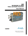
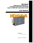
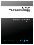
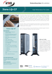
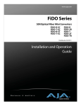
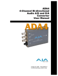
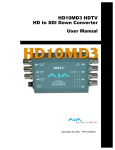
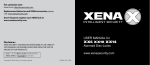
HD10CEA
SDI/HD-SDI to Analog
Audio/Video Converter
User Manual
®
July 11, 2008
2
Trademarks
AJA®, KONA®, and XENA® are registered trademarks of AJA Video, Inc. Io HD™ and Io™ are
trademarks of AJA Video, Inc.
All other trademarks are the property of their respective holders.
Notice
Copyright © 2008 AJA Video, Inc. All rights reserved. All information in this manual is subject to
change without notice. No part of the document may be reproduced or transmitted in any form,
or by any means, electronic or mechanical, including photocopying or recording, without the
express written permission of AJA Inc.
FCC Emission Information
This equipment has been tested and found to comply with the limits for a Class A digital device,
pursuant to Part 15 of the FCC Rules. These limits are designed to provide reasonable protection
against harmful interference when the equipment is operated in a commercial environment. This
equipment generates, uses and can radiate radio frequency energy and, if not installed and used in
accordance with the instruction manual, may cause harmful interference to radio
communications. Operation of this equipment in a residential area is likely to cause harmful
interference in which case the user will be required to correct the interference at his own expense.
Changes or modifications not expressly approved by AJA Video can effect emission compliance
and could void the user’s authority to operate this equipment.
Contacting Support
To contact AJA Video for sales or support, use any of the following methods:
443 Crown Point Circle, Grass Valley, CA. 95945 USA
Telephone: 800.251.4224 or 530.274.2048
Fax: 530.274.9442
Web: http://www.aja.com
Support Email: [email protected]
Sales Email: [email protected]
When calling for support, have all information at hand prior to calling.
Limited Warranty
AJA Video warrants that this product will be free from defects in materials and workmanship for a period of five years from
the date of purchase. If a product proves to be defective during this warranty period, AJA Video, at its option, will either
repair the defective product without charge for parts and labor, or will provide a replacement in exchange for the defective
product.
In order to obtain service under this warranty, you the Customer, must notify AJA Video of the defect before the expiration
of the warranty period and make suitable arrangements for the performance of service. The Customer shall be responsible
for packaging and shipping the defective product to a designated service center nominated by AJA Video, with shipping
charges prepaid. AJA Video shall pay for the return of the product to the Customer if the shipment is to a location within
the country in which the AJA Video service center is located. Customer shall be responsible for paying all shipping charges,
insurance, duties, taxes, and any other charges for products returned to any other locations.
This warranty shall not apply to any defect, failure or damage caused by improper use or improper or inadequate
maintenance and care. AJA Video shall not be obligated to furnish service under this warranty a) to repair damage resulting
from attempts by personnel other than AJA Video representatives to install, repair or service the product, b) to repair
damage resulting from improper use or connection to incompatible equipment, c) to repair any damage or malfunction
caused by the use of non-AJA Video parts or supplies, or d) to service a product that has been modified or integrated with
other products when the effect of such a modification or integration increases the time or difficulty of servicing the
product.
THIS WARRANTY IS GIVEN BY AJA VIDEO IN LIEU OF ANY OTHER WARRANTIES, EXPRESS OR
IMPLIED. AJA VIDEO AND ITS VENDORS DISCLAIM ANY IMPLIED WARRANTIES OF
MERCHANTABILITY OR FITNESS FOR A PARTICULAR PURPOSE. AJA VIDEO’S RESPONSIBILITY TO
REPAIR OR REPLACE DEFECTIVE PRODUCTS IS THE WHOLE AND EXCLUSIVE REMEDY PROVIDED TO
THE CUSTOMER FOR ANY INDIRECT, SPECIAL, INCIDENTAL OR CONSEQUENTIAL DAMAGES
IRRESPECTIVE OF WHETHER AJA VIDEO OR THE VENDOR HAS ADVANCE NOTICE OF THE
POSSIBILITY OF SUCH DAMAGES.
AJA HD10CEA SDI/HD-SDI to Analog Audio/Video Converter User Manual — Introduction
Introduction
The HD10CEA converts SDI/HD-SDI video with embedded audio to analog video
and 4 channel balanced analog audio. SD video outputs can be configured as YPbPr
(Betacam or SMPTE/EBU-N10), RGB, composite or YC (S-Video). HD video
outputs can be configured as YPbPr or RGB. The 4 audio channels can be selected
from group 1-4. Audio and video output connections are available on a 25 pin “D”
subminiature connector (breakout cable supplied). All video/audio configuration is
done by external dipswitch selection. This versatile, low-cost, miniature monitoring
solution also outputs two loop-thru SDI/HD-SDI outputs.
Features
1
• Digital to Analog Audio and Video Converter
• SDI/HD-SDI with Embedded Audio Input
• SD Component or Composite Video Outputs (SD Input)
• HD Component Video Outputs (HD Input)
• 4 Channel Balanced Audio Output
• 2 Equalized, Loop-Thru SD/HD-SDI Outputs
• Selectable Audio Channel Pair/Group
• Audio/Video Configurable via Dipswitch
• Uses 5-18Vdc power (supply sold separately)
Input Formats
Standard Definition inputs supported:
• 525i 29.97 and 625i 25
High Definition inputs supported:
• 1080p component 23.98psf/24psf
• 1080i component 50/59.94/60
• 720p component 50/59.94/60
Block Diagram
DIP
Switch
User
Interface
for
Feature
Selection
Break-out
Cable
Channel 1 Right
Audio
Serial
Video
with Embedded Audio
In
Channel 1 Left
Channel 2 Right
ReClock
Video and
Audio D/A
Channel 2 Left
COMPONENT OUTPUTS (selected by DIP switch)
Clocked Loop-through SDI Outputs
Filter
COMP
B
Y
Filter
Y
G
Pb
Filter
C
R
Pr
Serial Video Out 1
Serial Video Out 2
HD10CEA Converter, Simplified Block Diagram
3
4
I/O Connections
Audio and Video
Configuration
Determined by
DIP switch on
back of
Converter
SD/HD-SDI Input
BNC
SD/HD-SDI Loop
Output 1
Audio and Video
Output
via Cable
Snake Connector
(25-pin D)
Lock LED
SD/HD-SDI Loop
Output 2
+ 5-18VDC
Power
Input
Green: Lock to SD
Red: Lock to HD
Right Side
View
HD10CEA Converter
User Controls
The user interface for the HD10CEA is an 8-switch DIP
accessible through a cut-out in the bottom of the unit. Use
the DIP switches to configure video outputs, pedestal,
select audio channel groups, and set audio level.
Switches 1 through 3 configure video output format.
Switches 4 through 7 select the audio channel group and
audio level. The exact function of each DIP switch and
what it controls is described on the following pages.
AUX
DIP Switches
LEFT
RIGHT
OFF
ON
AJA HD10CEA SDI/HD-SDI to Analog Audio/Video Converter User Manual — User Controls
Switch 1—Selects YPbPr/YC or RGB Component Outputs
:
RIGHT
LEFT (default)
RGB:
Selects RGB
YPbPr/YC:
Selects YPbPr/YC component video out
Switch 2—Select Component (COMPNT) or Composite (CMPSTE) Out
:
1
RIGHT
LEFT (default)
CMPSTE:
Selects composite video output
COMPNT:
Selects component video output
Switch 3—Configure Pedestal For Composite
:
RIGHT
LEFT (default)
7.5 IRE pedestal for NTSC (also selects
BETA 525 levels for YPbPr)
No pedestal (also selects SMPTE levels for
YPbPr)
Note: There is no effect with 625 input.
Switches 4 and 5—Select an Audio Channel Group for Output
Together these two switches select the group of audio channels that will be routed to the XLR
connectors on the break-out cable. Each audio group has four channels, corresponding to the
four connectors. The following table shows the group and channel assignments selected by
each switch position for the two DIP switches.
:
Group and Channels
S4
S5
Group 0 (default):
Channels 1 to 4
0ff (Left)
0ff (Left)
Group 1:
Channels 5 to 8
0n (Right)
0ff (Left)
Group 2:
Channels 9 to 12
0ff (Left)
0n (Right)
Group 3:
Channels 13 to 16
0n (Right)
0n (Right)
5
6
Switches 6 and 7—Select Audio Levels for Output
Together these two switches select audio output levels at the XLR outputs. The following
table shows the level selected by each switch position for the two DIP switches.
Audio Level (dbu)
S6
S7
+24.00 dBu (default)
0ff (Left)
0ff (Left)
+18.00 dBu
0n (Right)
0ff (Left)
+15.00 dBu
0ff (Left)
0n (Right)
+12.00 dBu
0n (Right)
0n (Right)
Switch 8 (AUX)—Switches Component Levels to BETACAM-Japan
:
Format Selection
RIGHT
LEFT (default)
Select NTSC-J levels for Component
BETACAM outputs
Normal operation (NTSC level outputs)
The table below shows how to configure dipswitches 1, 2, 3 and 8 for many popular
formats.
SW# 1
SW# 2
SW# 3
SW# 8
SD NTSC Composite and S-Video
N/A
Right
Left
N/A
SD NTSC Composite and S-Video-Japan
N/A
Right
Right
N/A
SD 60 Component SMPTE
Left
Left
Right
N/A
SD 60 Component BETACAM
Left
Left
Left
N/A
SD 60 Component BETACAM-Japan
Left
Left
Left
Right
SD 60 RGB with Pedestal
Right
Left
Left
N/A
SD 60 RGB without Pedestal
Right
Left
Right
N/A
HD 60/50 Component SMPTE
Left
N/A
N/A
N/A
HD 60/50 Component RGB
Right
N/A
N/A
N/A
SD PAL Composite and S-Video
N/A
Right
N/A
N/A
SD 50 Component N-10
Left
Left
N/A
N/A
Format
AJA HD10CEA SDI/HD-SDI to Analog Audio/Video Converter User Manual — Installation
Installation
Typically, HD10CEA installation consists of the following steps:
1. Ensure the HD10CEA is disconnected from power.
2. Connect equipment to the convertor BNCs and cable snake BNCs/XLRs.
3. Apply +5-18VDC power to the converter (AJA power supply model DWP or DWPU).
Specifications
1
Item
Specification
Inputs
SDI/HD-SDI w/Embedded Audio, 1x BNC
Formats
Standard Definition inputs supported:
525i 29.97 and 625i 25
High Definition inputs supported:
1080p component 23.98psf/24psf
1080i component 50/59.94/60
720p component 50/59.94/60
Outputs
SD Video: YPbPr - SMPTE, EBU-N10, Betacam, RGB,
NTSC, PAL, YC (S-Video)
HD Video: YPbPr, RGB
Audio: 4 Channel Balanced
Video/Audio Outputs on 25 Pin D Connector
2 SDI/HD-SDI Equalized Loop-Thru, 2x BNC
User Controls
External Dipswitch
Video Format
Pedestal
H/V Blanking
Audio Group 1 - 4
Audio Level (adjustable via switch selection):
+24, +18, +15, +12 dBu, Full Scale Digital
Size
5.8” x 3.1” x 1” (147 x 79 x 25mm)
Power
+5-18VDC, Regulated, 4 Watts
Requires Power Supply (AJA power supply model DWP or
DWP-U recommended)
7
8