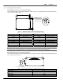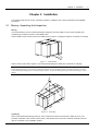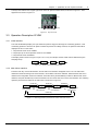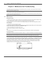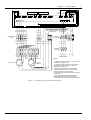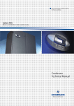
1
Next Generation Critical Cooling for Room and Row Liebert PEX Efficiency And Reliability For High Availability Cooling Condenser User Manual Liebert.PEX Condenser User Manual Version Revision date BOM V1.0 May 27, 2010 31011829 Emerson Network Power provides customers with technical support. Users may contact the nearest Emerson local sales office or service center. Copyright © 2010 by Emerson Network Power Co., Ltd. All rights reserved. The contents in this document are subject to change without notice. Emerson Network Power Co., Ltd. Address: No.1 Kefa Rd., Science & Industry Park, Nanshan District 518057, Shenzhen China Homepage: www.emersonnetworkpower.com.cn E-mail: [email protected] Contents Chapter 1 Overview ............................................................................................................................................................ 1 1.1 Classification And Models..................................................................................................................................... 1 1.2 Model Description ................................................................................................................................................. 1 1.3 Main Components................................................................................................................................................. 1 1.4 Technical Parameters ........................................................................................................................................... 2 1.4.1 Mechanical Parameters ............................................................................................................................. 2 1.4.2 Mounting Base Dimensions ....................................................................................................................... 3 1.4.3 Parameters Of Operating Environment ..................................................................................................... 4 1.4.4 Parameters Of Storage Environment......................................................................................................... 4 Chapter 2 Installation .......................................................................................................................................................... 5 2.1 Moving, Unpacking And Inspection....................................................................................................................... 5 2.2 Installation Notes .................................................................................................................................................. 6 2.3 Space Requirements ............................................................................................................................................ 6 2.4 Installation Procedures ......................................................................................................................................... 7 Chapter 3 Application Of Fan Speed Controller .................................................................................................................. 9 3.1 Wiring Terminals ................................................................................................................................................... 9 3.2 HMI ..................................................................................................................................................................... 10 3.3 Operation Description Of HMI ............................................................................................................................. 11 3.3.1 Initial Interface ......................................................................................................................................... 11 3.3.2 Main Menu Interface ................................................................................................................................ 11 Chapter 4 Maintenance And Troubleshooting ................................................................................................................... 14 4.1 Maintenance ....................................................................................................................................................... 14 4.2 Troubleshooting .................................................................................................................................................. 15 Appendix 1 Circuit Diagram............................................................................................................................................... 16 Chapter 1 Overview 1 Chapter 1 Overview This chapter introduces the classification and models, model description, main components and technical parameters of the Liebert.PEX condenser (condenser for short). 1.1 Classification And Models The condenser is classified into two types: single circuit and dual circuit. The single circuit has a set of discharge/liquid pipe to match the single refrigeration system of indoor unit. The dual circuit has two sets of discharge/liquid pipes to match the two separate refrigeration systems of indoor unit. The condenser is available in 17 models. The classification and models are listed in Table 1-1. Table 1-1 Condenser models Classification Model Single circuit LS12, LS18, LSF24, LSF32, LSF38, LSF42, LSF52, LSF62, LSF72, LSF76, LSF85 Dual circuit LDF42, LDF52, LDF62, LDF72, LDF76, LDF85 1.2 Model Description Taking LSF62 for example, the model description of the condenser is shown in Figure 1-1. L SF 62 Model code SF: single circuit with fan speed controller DF: dual circuit with fan speed controller Liebert Figure 1-1 Model description 1.3 Main Components The main components of the condenser include the heat exchanger, fan, fan speed controller and pressure sensor. The heat exchanger is inside the condenser, and the appearance and position of other components are shown in Figure 1-2 and Figure 1-3. Fan ECB: electrical control box (with a fan speed controller inside) Isolation switch Pressure sensor Figure 1-2 PEX condenser (single fan, single circuit) Liebert.PEX Condenser User Manual 2 Chapter 1 Overview Fans Isolation switch Electrical control box (with a fan speed controller inside) Pressure sensors (2 pcs) Figure 1-3 PEX condenser (double fans, dual circuit) 1.4 Technical Parameters 1.4.1 Mechanical Parameters The condenser structure is shown in Figure 1-4. The mechanical parameters of each model are listed in Table 1-2. LL W H H Front view Figure 1-4 Side view Structure (double fans) (unit: mm) Table 1-2 Model Weight (kg) Fan diameter (mm) LSF12 80 500 Mechanical parameters Fan number 1 Dimension (mm) L H W 924 990 599 LSF18 80 500 1 924 990 599 LSF24 105 710 1 1374 990 689 LSF32 110 710 1 1374 990 689 LSF38 120 800 1 1374 990 695 LSF42 130 800 1 1574 1273 695 LSF52 140 800 1 1574 1273 695 LSF62 150 710 2 1874 1273 689 LSF72 150 710 2 1874 1273 689 LSF76 220 800 2 2374 1273 695 LSF85 230 800 2 2374 1273 695 LDF42 130 800 1 1574 1273 695 LDF52 140 800 1 1574 1273 695 LDF62 160 710 2 2074 1273 689 LDF72 160 710 2 2074 1273 689 LDF76 220 800 2 2374 1273 695 LDF85 230 800 2 2374 1273 695 Liebert.PEX Condenser User Manual Chapter 1 Overview 3 1.4.2 Mounting Base Dimensions Mounting base dimensions for horizontal installation The mounting base figure for horizontal installation is shown in Figure 1-5, and the specific mounting base dimensions of each model are listed in Table 1-3. L' D D D Amplified part figure D D Installation holes (8 holes in total ) H' D Figure 1-5 Table 1-3 Mounting base figure for horizontal installation (unit: mm) Mounting base dimensions for horizontal installation (unit: mm) Model Dimension (L' × H' × D) Model Dimension (L' × H' × D) LSF12 676 × 837 × 53 LSF76 2126 × 1120 × 53 LSF18 676 × 837 × 53 LSF85 2126 × 1120 × 53 LSF24 1126 × 837 × 53 LDF42 1326 × 1120 × 53 LSF32 1126 × 837 × 53 LDF52 1326 × 1120 × 53 LSF38 1126 × 837 × 53 LDF62 1826 × 1120 × 53 LSF42 1326 × 1120 × 53 LDF72 1826 × 1120 × 53 LSF52 1326 × 1120 × 53 LDF76 2126 × 1120 × 53 LSF62 1626 × 1120 × 53 LDF85 2126 × 1120 × 53 LSF72 1626 × 1120 × 53 Note The installation holes are long and flat holes. It is recommended to use M10 × 20 bolts to fix the mounting base. Mounting base dimensions for vertical installation The mounting base figure for vertical installation is shown in Figure 1-6, and the specific mounting base dimensions of each model are listed in Table 1-4. a 20 Figure 1-6 Table 1-4 250 490 452 102 20 Mounting base figure for vertical installation (top view) (unit: mm) Mounting base dimensions for vertical installation (unit: mm) Model LSF12, LSF18 LSF24, LDF32, LSF38 LSF42, LDF42, LSF52, LDF52 LSF62, LSF72 LDF62, LDF72 Dimension ‘a’ 830 1280 1480 1780 1980 Liebert.PEX Condenser User Manual 4 Chapter 1 Overview Model LSF76, LDF76, LSF85, LDF85 Dimension ‘a’ 2280 Note 1. The installation holes are long and flat holes. It is recommended to use M10 × 20 bolts to fix the mounting base. 2. The upper condenser must be installed on a rack during vertical installation, and the cushion pads should be installed between the condenser and the rack for reducing vibration. It is prohibited to stack two condensers through bolt connection. 1.4.3 Parameters Of Operating Environment Refer to Table 1-5 for parameters of operating environment. Table 1-5 Item Installation position Ambient temperature Parameters of operating environment Requirement The standard equivalent distance between the indoor unit and the condenser is 30m. Vertical difference* ∆H: -5m ≤ ∆H ≤ 20m. Installation mode: horizontal or vertical mode Outdoor temperature: -20°C ~ +45°C. Low temperature accessories are required if the temperature is between -35°C and -20°C Outdoor humidity: 5%RH ~ 95%RH 400V ± 10%, 50Hz ≤ 1000m. Derating is required if the altitude exceeds 1000m Electrical control box: IP55; unit: IP20; fan motor: IP54 Ambient relative humidity Operation power Altitude Protection level Note*: Condenser fins have a corrosion resistant coating designed to provide maximum life expectancy for the heat exchanger and protect the aluminium fins from harsh environments. The high performance coating has been tested for 2000 hours exposure to a 5% neutral salt spray test in accordance with ASTMB117 without impact to the coating Note When the equivalent distance between the indoor unit and the condenser exceeds 30m, refer to 5.1 Refrigerant Tubing System in Liebert.PEX Series Air Conditioner Technical Manual for the requirement of the line equivalent length. 1.4.4 Parameters Of Storage Environment Refer to Table 1-6 for parameters of storage environment. Table 1-6 Item Storage environment Ambient temperature Ambient relative humidity Storage time Parameters of storage environment Requirement Clean indoor environment with good ventilation and no dust -40°C ~ +70°C 5%RH ~ 85%RH The total storage time should not exceed 6 months. Otherwise, the performance needs to be re-calibrated Liebert.PEX Condenser User Manual Chapter 2 Installation 5 Chapter 2 Installation This chapter introduces the moving, unpacking, inspection, installation notes, space requirements and installation procedures. 2.1 Moving, Unpacking And Inspection Moving It is recommended to use the mechanical transport equipment such as a forklift or a crane when unloading and transferring the condenser closest to the installation site. When a forklift is used, insert the tines of the forklift shown in Figure 2-1 (taking the single fan condenser for example). Fo dir rklif ec t tio n Figure 2-1 Forklift direction When a crane is used, refer to Figure 2-2 to lift the package (taking the double fans condenser for example). Note When lifting the package, fix the cable by leading it through the slots located at the bottom of the pallet. Otherwise, the cable may slide during the lifting process, and the package may fall to the ground, damaging the pipes inside and resulting in system leakage. Figure 2-2 Crane lifting Unpacking Remove the timber frame package and foam of the condenser but reserve the protection cardboard of fins. The protection cardboard of fins and the cushion pad of U tube located at the end of the condenser should be removed after the condenser is in its installation position. Liebert.PEX Condenser User Manual 6 Chapter 2 Installation Note 1. If the condenser is to be placed horizontally, you should complete the installation of legs while the condenser is located vertically. 2. When moving the condenser by hand, to avoid distortion and system leakage, do not touch the copper pipes. Inspection After the product arrival, you should check the accessories against the packing list. If any parts are found missing or damaged, please report to the carrier immediately. If any covert damage is found, please report to the carrier and the distributor immediately. 2.2 Installation Notes The installation notes of the condenser are as follows: 1. To ensure the heat dissipation capacity, install the condenser in the place with smooth airflow. Do not install it where the coil of the condenser may be obstructed by dust or snow. Ensure that there is no steam or waste heat around. 2. If possible, the horizontal installation is recommended to reduce the noise. 3. The condenser should be installed away from the residential areas (≥ 15m). 4. Be careful not to damage the waterproof layer and observe the local regulations when the condenser is installed on the roof of the building. 5. Position the condenser higher than the indoor unit to ensure normal oil return. 6. Follow the installation arrows on the condenser for correct installation direction. 2.3 Space Requirements Note 1. A 4000mm clearance is required around the condenser air outlet. 2. 600mm service spaces are required on the four sides of the condenser. The condenser needs sufficient installation and service space around the installation place. The specific space requirements are shown in Figure 2-3 and Figure 2-4. Airflow Airflow 1200 600 450 Figure 2-3 Horizontal installation space requirement (unit: mm) 4000 Airflow Figure 2-4 Vertical installation space requirement (unit: mm) Liebert.PEX Condenser User Manual 600 Chapter 2 Installation 7 2.4 Installation Procedures Note Before commencing installation hot works, release all nitrogen holding charges from the indoor and outdoor units. Installing pipelines Note 1. Protect copper pipes from heat sources. Isolate copper pipes from structures or other obstacles using rigid supports. Avoid dust, water vapor and irrelevant objects from entering copper pipes. 2. Use a good quality, silver-based solder for all brazed connections. Use refrigeration grade copper pipes and fittings throughout the installation. Purge all pipes with nitrogen during brazing to prevent oxidation. 1. Identify the pipe sizes Refer to 2.6 Installing Unit Pipes in Liebert.PEX Series Air Conditioner User Manual for pipe sizes. 2. Identify the condenser installation height Refer to 2.6 Installing Unit Pipes in Liebert.PEX Series Air Conditioner User Manual for installation height. 3. Install the pipes Install the pipes according to local and national codes and standards. Connecting external power (external power supply of the condenser) 1. Identify the cable specifications Select the power supply cables and start/stop signal cables of the condenser according to site conditions, such as the distance between the indoor unit and the condenser. Table 2-1 Operation current of fan under 400V voltage Condenser Model LSF12 LSF18 LSF24 LSF32 LSF38, LSF42, LSF52, LDF42, LDF52 LSF62, LSF72, LDF62, LDF72 LSF76, LSF85, LDF76, LDF85 FLA (A) 0.79 1.45 1.65 1.05 2.4 3.3 4.8 Note 1. It is recommended to use the 20AWG (0.52mm2) cable as the condenser start/stop signal cable. 2. The outdoor air cooled condenser requires a three-phase, neutral and earth power supply. The indoor PEX unit is the recommended point of connection for this electrical service and includes a three-pole circuit breaker rated at 16 amps. 3. The cables should not contact hot objects, such as the copper pipe and water pipe without insulation, to avoid damaging the insulation layers. 4. The cables should be connected in accordance with the local regulations. 2. Connect the cables See Figure 2-5, Figure 2-6 and Appendix 1 Circuit Diagram for the connections of external power cables. Liebert.PEX Condenser User Manual 8 Chapter 2 Installation Waterproof joint of external power cables by others Accessing terminal of external power supply (single fan) Figure 2-5 Fan speed controller board Connection figure of single fan external power cables (taking LDF42 for example) Waterproof joint of external power cables by others Accessing terminal of external power supply (double fans) Figure 2-6 Fan speed controller board Connection figure of double fans external power cables (taking LDF62 for example) Note 1. The external power cables and compressor signal cables enter the electrical control box through the waterproof joint of external power cable whose inner diameter is Φ10mm. 2. After connecting the external power cables, apply waterproof sealant treatment to ensure the good waterproof performance of electrical control box. 3. The phase sequence of three-phase AC input (L1, L2, L3) must be correct. Otherwise, the fan speed controller will generate the phase loss alarm, and there will be no AC output. 4. For dual circuit condenser (such as LDF42, LDF52, LDF62, LDF72, LDF76 and LDF85), the four condenser start/stop signal cables should be paralleled at the terminal block of indoor unit before connection; for single circuit condenser, the two condenser start/stop signal cables can be connected directly. Charging refrigerant and adding cooling oil Refer to 2.6 Installing Unit Pipes in Liebert.PEX Series Air Conditioner User Manual for charging refrigerant and adding cooling oil. Liebert.PEX Condenser User Manual Chapter 3 Application Of Fan Speed Controller 9 Chapter 3 Application Of Fan Speed Controller This chapter introduces the use of the fan speed controller, which includes the definitions of wiring terminals, introduction of human-machine interface (HMI) and operation of HMI. This chapter is mainly provided for the factory maintenance personnel. It is recommended that users should not operate the fan speed controller unless necessary. Note The configured fan number must be the same as the number of the actual fans, or else a false alarm will be generated. Refer to Configuration data main menu interface in 3.3.2 Main Menu Interface for detailed settings. 3.1 Wiring Terminals The wiring terminals are located on the fan speed controller board (see Figure 2-5 and Figure 2-6). Their distribution is shown in Figure 3-1 and the definitions are listed in Table 3-1. Refer to Appendix 1 Circuit Diagram for detailed connections. J8 (SCRTemp) LCD and keys D15 J9 W V J3 (HP1) J4 (HP2) U J1 J17 J18 L3 L2 L1 J14 (HP2) J15 (HP1) J5 (Out Temp) J11 (RS232) J7 (Fan1Sta) J10 (Fan2Sta) PE J6 (CompSta) D16 Figure 3-1 Table 3-1 Silk print Layout of wiring terminals Definitions of wiring terminals Definition J1 AC I/O terminal J9 Passive dry contactor relay output (for the power switch of fan power supply contactor) J3 (HP1) J4 (HP2) J15 (HP1) J14 (HP2) J17, J18 D22 Input terminal of voltage pressure sensor 1 (spare) Input terminal of voltage pressure sensor 2 (spare) Input terminal of current pressure sensor 1 Input terminal of current pressure sensor 2 Jumpers of current pressure sensor Definition of pins PE: protection earth L1, L2, L3: three-phase AC input U, V, W: three-phase AC output, which connects with the power supply terminals The middle terminal pin without logo is reserved Pin 1: normally closed terminal of relay, which is reserved Pin 2: common terminal of relay, which is used for AC input Pin 3: normally open terminal of relay, which is used for AC output Pin 1: positive terminal of 5V power Pin 2: input terminal of 0.5V ~ 4.5V pressure voltage signal Pin 3: negative terminal of 5V power Pin 1: positive terminal of 12V power Pin 2: input terminal of 4mA ~ 20mA pressure current signal Current pressure sensor: the short circuit ring must be installed on the jumpers Voltage pressure sensor: the open status of jumpers must be kept Liebert.PEX Condenser User Manual 10 Chapter 3 Application Of Fan Speed Controller Silk print J5 (Out Temp) J11 (RS232) J7 (Fan1Sta) J10 (Fan2Sta) Definition Input terminal of ambient temperature sensor (spare) Serial communication interface (used for maintenance) Detecting terminal of fan 1 over temperature state Detecting terminal of fan 2 over temperature state Detecting terminal of compressor state Definition of pins Pin 1: input terminal of temperature signal Pin 2: signal ground Pin 1: communication ground Pin 2: reception terminal of communication Pin 3: transmission terminal of communication Pin 1: output terminal of 19Vac signal Pin 2: return terminal of 19Vac signal J6 (CompSta) Note: J8 (SCRTemp) in Figure 3-1 is the interface of fan speed controller board, and not to be used by users 3.2 HMI The fan speed controller operation and setup is provided through indicators, RS232 serial communication port, keys and LCD. Indicators There are three indicators (see Figure 3-1) on the fan speed controller board. See Table 3-2 for the functions of indicators. Table 3-2 Silk print D16 Definition Color Power indicator D22 Run indicator D15 Power switch controlling indicator of AC contactor Functions of indicators State Green Green On Off On or off Blinking at 1Hz (slowly) Blinking at 5Hz (quickly) On Red Off Function The CPU circuit of fan speed controller board is supplied with 5V power The fan speed controller board is faulty The fan speed controller board is faulty The system is running normally without alarm There is an alarm or the compressor is shut down The control switch which supplies the AC contactor with the driving power is open The control switch which supplies the AC contactor with the driving power is closed RS232 serial communication port The RS232 serial communication port is a port to connect the computer using factory-defined protocol. It is used for factory commissioning and maintenance. Keys and LCD The keys and LCD, which can realize the functions in Table 3-3, provide the HMIs for maintenance personnel. Refer to 3.3 Operation Description Of HMI for operation of keys and LCD HMI. Table 3-3 NO. 1 Function Query the acquisition data in real time Function descriptions of keys and LCD Description The acquisition data include condensing pressure, ambient temperature, silicon controlled rectifier (SCR) temperature and output percentage The current alarm data include phase loss alarm, SCR over temperature, fan 1 over temperature, fan 2 over temperature, pressure sensor failure, EEPROM read fault alarm, SCR temperature sensor failure and abnormal frequency 2 Query the current alarm data in real time 3 Query the historical alarm data in real time The latest saved 100 historical alarms can be queried 4 Modify the configured parameters in real time The configured parameters include running pressure, pressure controlling range, minimum voltage, maximum voltage, fan number and pressure sensor type; or resume the default values Liebert.PEX Condenser User Manual Chapter 3 Application Of Fan Speed Controller 11 The keys and LCD are on the upper right corner of the fan speed controller board, as shown in Figure 3-1. Their appearance is shown in Figure 3-2. LCD ENT key ESC key UP key DOWN key Figure 3-2 Keys and LCD 3.3 Operation Description Of HMI 3.3.1 Initial Interface The LCD will alternately display ‘F01’ (the maximum pressure logo) and the larger of condensing pressure 1 and condensing pressure 2 when the fan speed controller is powered on initially. However, the pressure value will be displayed as ‘88.8’ on the LCD if: 1. The pressure sensor is not installed. 2. The jumper cap of current pressure sensor is not installed. 3. The pressure sensor is disabled. The display order is shown in Figure 3-3 (the ‘16.1’ is only an example, and the actual value is determined by the sampling result). F01 16.1 Figure 3-3 F01 16.1 Display order of the initial interface 3.3.2 Main Menu Interface Press the ESC key on the initial interface, and the main menu interface will appear on the LCD. The main menu interfaces include the analog main menu interface, current alarm main menu interface, historical alarm main menu interface and configuration main menu interface. Press the UP key and DOWN key to select a different main menu interface, and press the ENT key to enter the submenu of the current main menu on the main interface. The switching operation processes and orders of the main menus are shown in Figure 3-4. F - DOWN key A Analog main menu interface - DOWN key H UP key Current alarm main menu interface - DOWN key C UP UP Configuration main key Historical alarm main key menu interface menu interface DOWN key UP key Figure 3-4 - Switching operation processes and orders of the main menus Liebert.PEX Condenser User Manual 12 Chapter 3 Application Of Fan Speed Controller Analog main menu interface Press the ENT key to enter the analog submenu interface when the current main menu interface shows ‘F--’ (the symbol of analog main menu). The switching operation processes and orders of the analog submenu are shown in Figure 3-5. Analog main menu - F ENT key DOWN key ESC key Analog submenu shows the ID and values circulary F01 16.1 F02 16.1 F03 .0 F04 -15 F05 60 F06 88 Initial interface Analog ID definitions F01: The maximum pressure between the pressure 1 and pressure 2; 88.8 will be shown when the pressure sensor is disabled F02: Pressure 1 F03: Pressure 2 F04: Ambient temperature F05: SCR temperature F06: Output voltage percentage UP key Figure 3-5 Switching operation processes and orders of the analog submenu Current alarm main menu interface Press the ENT key to enter the current alarm submenu interface when the current main menu interface shows ‘A--’ (the symbol of current alarm main menu). The switching operation processes and orders of the current alarm submenu are shown in Figure 3-6. See Table 4-1 for generating conditions and troubleshooting. Current alarm main menu interface - A ENT key When there is an alarm, the XX of alarm ID is the number from 00 DOWN key - - ESC key No alarm or AXX AXX AXX F - Figure 3-6 AXX UP key Current alarm ID definitions A00: Phase loss alarm A01: SCR over temperature A02: Fan 1 over temperature A03: Fan 2 over temperature A04: Pressure sensor failure A05: EEPROM read fault A06: SCR temperature sensor failure A07: Abnormal frequency Switching operation processes and orders of the current alarm submenu Liebert.PEX Condenser User Manual Chapter 3 Application Of Fan Speed Controller 13 Historical alarm main menu interface Press the ENT key to enter the historical alarm submenu interface when the current main menu interface shows ‘H--’ (the symbol of historical main menu). The switching operation processes and orders of the historical main menu are shown in Figure 3-7. Historical alarm main menu interface ENT key H- - The radix point is the space mark between the number order and alarm ID. The number is the alarm number and from1 whcih is the present historical alarm. 0 is the 100th historical alarm. X is the historical alarm ID. When there is no alarm, '-' will be shown DOWN key Historical alarm ID definitions 0: Phase loss alarm 1: SCR over temperature 2: Fan 1 over temperature 3: Fan 2 over temperature 4: Pressure sensor failure 5: EEPROM read fault 6: SCR temperature sensor failure 7: Abnormal frequency -: No alarm 1.X 2.X ESC key 99.X F- - 0.X UP key Analog main menu Figure 3-7 Switching operation processes and orders of the historical main menu Configuration data main menu interface Note The configuration data main menu interface is designed only for maintenance personnel to set parameters, others are prohibited to operate it. Press the ENT key to enter the configuration data submenu interface when the current main menu interface shows ‘C--’ (the symbol of configuration data main menu). The switching operation processes and orders of the configuration data main menu are shown in Figure 3-8. Configuration main menu interface ENT key ESC key C- - Configuration value Configuration ID selected submenu changed submenu (using UP key DOWN and UP keys) C01 13 C02 ESC key C03 C04 4 ESC key ENT key C05 30 100 1 C06 888 Prompt interface of successful change Configuration ID definitions ENT key C01: Pressure set Pset C02: Pressure band Pband C03: Minimum voltage Vmin C04: Maximum voltage Vmax C05: Fan number C06: Sensor type C99: Resume the default 2 C99 DOWN key Figure 3-8 Switching operation processes and orders of the configuration data main menu Liebert.PEX Condenser User Manual 14 Chapter 4 Maintenance And Troubleshooting Chapter 4 Maintenance And Troubleshooting This chapter introduces the maintenance and troubleshooting of the condenser. Users should check the condenser regularly and solve the problems in time. Note 1. The maintenance of the condenser must be done by technicians. 2. Except for the commissioning items that must be carried out with power-on, during maintenance, the power of the indoor unit and the air switch of the condenser must be cut off. 4.1 Maintenance Refrigeration system 1. Check that the refrigeration pipes are firmly fixed. The refrigeration pipes shall not shake with the vibration of wall, earth or equipment frame. Otherwise, reinforce the refrigeration pipes with fastening objects. 2. Check that there is no oil on the accessories of all refrigeration pipes, and make sure that the pipes do not leak. Heat exchanger 1. Clean the fin of the heat exchanger regularly. 2. Clean the fin of the heat exchanger with compressed air or fin detergent (weakly alkaline) if the condenser airflow is blocked. Inverse airflow is good when the compressed air is used. 3. Check for damaged fins and maintain them in time. 4. Avoid snow accumulation around the condenser in winter. Fan Check that the fan runs normally. Check it for problems such as abnormal noise, vibration and bearing failure. Fan speed controller Check that the fan speed controller board operates normally. If not, replace it as illustrated in the following paragraph. Note Note that the positions of the bolt installation holes on the fan speed controller could be different on the actual product. The fan speed controller is inside the electrical control box (see Figure 1-2 and Figure 1-3). Rotate the isolation switch to ‘OFF’, and then remove the cover plate of the electrical control box, as shown in Figure 4-1. Remove the cover plate of the electrical control box before removing the fan speed controller board. Except for the seven bolts in Figure 4-2, other bolts are prohibited to remove. The bolt 1 and bolt 2, which are used to fix the heat sink on the fan speed controller board, must be fastened firstly. The heat sink must cling to the floor of the electrical control box. After installing the heat sink, use other five bolts to fix the fan speed controller board. OFF ON Figure 4-1 Fan speed controller board Liebert.PEX Condenser User Manual Chapter 4 Maintenance And Troubleshooting 15 Heat sink 散热片 Bolt 1 Fan speed controller board Bolt 2 Figure 4-2 Removing the fan speed controller board 4.2 Troubleshooting See Table 4-1 for alarm troubleshooting. Table 4-1 Alarm number ID Alarm name A00 Phase loss alarm A01 SCR over temperature A02, A03 Fan 1 over temperature, Fan 2 over temperature A04 Pressure sensor failure A05 EEPROM read fault A06 SCR temperature sensor failure A07 Abnormal frequency Table of alarm troubleshooting Cause One phase or two phases of three-phase voltage are lost The input connection is reversed The fan speed controller board has a hardware fault The fan cannot run normally The fan speed controller board has a hardware fault The fan cannot run normally The AC contactor supplying power for fan has fault or its wire cuts off The fan speed controller board has a hardware fault (the detecting circuit or SCR power supplying circuit has fault) The pressure sensor is not installed or its terminal connection is poor Jumper caps are not used to short terminals J17 and J18 of current pressure sensor Pressure sensor failed The fan speed controller board has a hardware fault The fan speed controller board has a hardware fault The SCR temperature sensor is not installed or its terminal connection is poor SCR temperature sensor failed The fan speed controller has a hardware fault The frequency of power supply voltage is wrong The fan speed controller has a hardware fault Troubleshooting Check that the three-phase voltage is correct Check the input order of wire Replace the fan speed controller board and compare the result of two boards Check that the fan runs normally Replace the fan speed controller board and compare the result of two boards Check that the fan runs normally Check the wiring of AC contactor; detect the auxiliary contact state of AC contactor Replace the fan speed controller board and compare the result of two boards Check the wiring of pressure sensor Install the jumper cap when the current pressure sensor is configured Replace the pressure sensor and compare the result of two boards Replace the fan speed controller board and compare the result of two boards Replace the fan speed controller board and compare the result of two boards Check the wiring of SCR temperature sensors (J8 SCRTemp, see Figure 3-1 for its position ) Replace the SCR temperature sensor and compare the result of two sensors Replace the fan speed controller board and compare the result of two boards Replace the fan speed controller board and compare the result of two boards Liebert.PEX Condenser User Manual 16 Appendix 1 Circuit Diagram Appendix 1 Circuit Diagram L1 02 Black Black Pressure sensor 2 J9 3 2 1 J3 HP1 W J4 HP2 03 03 Black 1 J15 HP1 J5 OutTemp J11 RS232 03 L1 04 04 05 3 4 5 Shell connecting to the earth J7 Fan1Sta J10 Fan2Sta J6 CompSta 02 Olivine Compressor signal Orange L3 Black Black Red Orange 2 04 Red U V Black J14 HP2 04 Pressure sensor 1 L2 02 L1 02 PE 01 02 Black Black Black Black Olivine 7 6 Wiring terminal block Air circuit breaker 8 Black 9 06 1L1 11 12 07 06 3L2 5L3 08 A1 Black 01 4T2 6T3 10 09 01 01 01 A2 V1 W1 01 L3 09 Remark: L2 L1 N PE External power 1. Connect the pressure sensor 1 only, when PEX condenser is a single circuit. 2. Connect the pressure sensor 1 and 2 with the copper pipe of PEX condenser, when PEX condenser is a dual circuit. 3. When mounted vertically, the lower header connects to pressure sensor 1 and the upper header connects to pressure sensor 2. 4. Both external power and compressor signal are wired in field. 5. The compressor signal cables should be in parallel and then connected into the electrical control board, when the indoor unit is a dual circuit. U1 TB PE 01 Black NO TB Fan 10 Isolation switch Black Black Black Orange 01 10 Black Black NO Contactor 1 2T1 14 13 Red Orange Black Olivine Black Black Black 06 10 01 Figure 1 Circuit diagram of the condenser with single fan Liebert.PEX Condenser User Manual Appendix 1 L1 03 Black J9 3 2 1 W V J3 HP1 J4 HP2 06 Pressure sensor 1 Pressure sensor 2 Black 10 White J14 HP2 J15 HP1 J5 OutTemp J11 RS232 10 11 05 Brown Orange 11 Compressor Brown Orange L3 L2 L1 04 04 04 L1 06 17 signal J7 Fan1Sta J10 Fan2Sta J6 CompSta U Black Black Black Black White Circuit Diagram PE Shell connecting 03 03 03 to the earth Black Black Black 03 Olivine Olivine 1 Wiring terminal block 2 3 4 6 5 12 13 14 7 15 16 Black Black Black Black White Brown Orange 07 07 07 08 09 09 09 1L1 3L2 5L3 A1 NO 1L1 3L2 5L3 A1 NO 9 17 18 10 10 10 Black Black Olivine Olivine 02 01 02 01 Black Black Black Isolation switch Contactor 2 Contactor 1 2T1 4T2 6T3 A2 8 Air circuit breaker NO 2T1 4T2 6T3 A2 NO L3 L2 L1 N PE Black Black Black Black Orange Black Black Black Black Orange 01 01 01 01 09 W1 Fan1 (remote) V1 U1 TB TB PE 01 01 External power 02 02 02 02 09 W1 V1 Remark: U1 TB TB PE 02 02 Figure 2 Fan2 (proximal) 1. Connect the pressure sensor 1 only, when PEX condenser is a single circuit. 2. Connect the pressure sensor 1 and 2 with the copper pipe of PEX condenser, when PEX condenser is a dual circuit. 3. When mounted vertically, the lower header connects to pressure sensor 1 and the upper header connects to pressure sensor 2. 4. Both external power and compressor signal are wired in field. 5. The compressor signal cables should be in parallel and then connected into the electrical control board, when the indoor unit is a dual circuit. Circuit diagram of the condenser with double fans Liebert.PEX Condenser User Manual Emerson Network Power Asia 7kijhWb_W J0'.&&ø&,+)*+ <0,'ø(ø/-*).-)- D[mP[WbWdZ J0,*ø)ø))/(&,& <0,*ø)ø))/(&,) 9^_dW J0.,ø-++ø.,&ø'&.&. <0.,ø-++ø.,&ø'&(*+ ?dZ_W J0/'ø((ø,-(&.&&& <0/'ø((ø(+.(.)+. FWa_ijWd J0/(ø*(ø),,((+(,je(. <0/(ø*(ø),,((+)& F^_b_ff_d[i J0,)ø(ø,(&),&& <0,)ø(ø,(&),/) ?dZed[i_W J0,(ø('ø(+')&&) <0,(ø('ø(+'&,(( I_d]Wfeh[ J0,+ø,*,-(('' <0,+ø,*,-&')& @WfWd J0.'ø)ø+*&).+/* <0.'ø)ø+*&)(/(* J^W_bWdZ J0,,ø(ø,'-.(,& <0,,ø(ø,'-.(--%-. Aeh[W J0.(ø(ø)*.)'+&& <0.(ø(ø+/(-..) L_[jdWc J0.*ø*ø)-,(./&. <0.*ø*ø)-,(./&/ CWbWoi_W J0,&)ø-..*+&&& <0,&)ø-..*+'.. [email protected] Emerson Network Power. J^[]beXWbb[WZ[h_d[dWXb_d]7jh^cZhh÷8g^i^XVa8dci^cj^inIB$ 79Fem[h 9edd[Yj_l_jo ;cX[ZZ[Z9ecfkj_d] ;cX[ZZ[ZFem[h :9Fem[h ?d\hWijhkYjkh[CWdW][c[djCed_jeh_d] EmersonNetworkPower.com Ekji_Z[FbWdj Fem[hIm_jY^_d]9edjhebi Fh[Y_i_ed9eeb_d] HWYai?dj[]hWj[Z9WX_d[ji I[hl_Y[i Ikh][Fhej[Yj_ed 8ki_d[iiø9h_j_YWb9edj_dk_jo";c[hiedD[jmehaFem[hWdZj^[;c[hiedD[jmehaFem[hbe]eWh[jhWZ[cWhaiWdZi[hl_Y[cWhaie\;c[hied;b[Yjh_Y (&'&;c[hied[b[Yjh_Y9e$ AP11ENT-PEXCondenserV1-UM