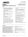
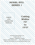
1
Design with the QorIQ T2081 and T1040 Processor Families FTF-NET-F0140 Xiaobo Xie Chun Chang | Application Engineer M A Y. 2 0 1 4 TM External Use Session Introduction • This session is relevant for customers designing with Freescale T2081 and T1040 family of QorIQ processors − Details the commonalities and differences − Examines the problems and solutions of common board design and migration from T1040 to T2081 − Provides practical examples based on existing Freescale designs TM External Use 1 Session Objectives • After completing this session you will be able to: − Identify the design collateral that exists to assist with T1040 and T2081 designs − Recognize the major design issues for the common board design and how they can be overcome − Use our design tips for high-speed interface design (eSDHC and SerDes) − Know where to go for assistance TM External Use 2 Agenda • T1040 and T2081 Overview • Hardware Compatibility • Software Compatibility • Pinout Comparison • Supporting Tools • Reference Documentation TM External Use 3 Agenda • T1040 and T2081 Overview − T1040 Block Diagram − T2081 Block Diagram − Device Comparison − Commonalities TM External Use 4 and Differences T1040 Power Architecture® e5500 256 KB Backside L2 Cache 32 KB D-Cache 32 KB I-Cache Security Fuse Processor Security Monitor CoreNet™ Coherency Fabric DIU 8 Port Switch Buffer Mgr. 1G 1G 1G 1G 1G 1G 1G 1G TDM/HDLC TDM/HDLC 2x USB 2.0 w/PHY Pattern Match Engine 2.0 SATA 2.0 2x I2C SPI, GPIO 2xDMA 1G 1G 1G 1G SATA 2.0 Queue Mgr. PCIe PCIe 5.0 (XoR, CRC) QUICC Engine Parse, Classify, Distribute PCIe 2x DUART Security PCIe eSDHC Peripheral Access Mgmt Unit PAMU IFC Power Management 256KB Platform Cache 32/64-bit 64-bit DDR3L/4 DDR2/3 Memory Memory Controller Controller Real Time Debug Watchpoint Cross Trigger Perf Monitor 8-Lane 5GHz SERDES Device • 780-pin FC-PBGA package • 23x23mm, 0.8mm pitch Power targets • Enable Convection cooled system design Datapath Acceleration • SEC- crypto acceleration • PME- Reg-ex Pattern Matcher TM External Use 5 CoreNet Trace Processor • 4x e5500, 64b, up to 1.4GHz • Each with 256KB backside L2 cache • 256KB Shared Platform Cache w/ECC • Supports up to 64GB addressability (36 bit physical addressing) Memory Subsystem • 32/64b DDR3L/4 Controller up to 1600MHz CoreNet Switch Fabric High Speed Serial IO • 4x PCIe Gen2 (5Gbps) Controllers • 2x SATA 2.0, 3Gbps • 2x USB 2.0 with PHY Network IO • FMan packet Parse/Classify/Distribute • Lossless Flow Control, IEEE 1588 • Up to 4x 10/100/1000 Ethernet Controllers • 8-Port Gigabit Ethernet Switch • QUICC Engine • HDLC, 2x TDM Green Energy Operation • Fanless operation quad-core 1.4GHz • Packet lossless deepsleep • Programmable wake-on-packet • Wake-on-timer/GPIO/USB/IRQ QorIQ T2081 Block Diagram T1 T1 T2 T2 T1 T1 T2 T2 Power™ Power™ Power™ Power™ e6500 e6500 e6500 e6500 32 KB 32 KB 32 KB 32 KB D-Cache I-Cache D-Cache I-Cache 32 KB 32 KB D-Cache I-Cache Pre-fetch 32 KB 32 KB D-Cache I-Cache 2MB Banked L2 Security Fuse Processor IFC PAMU Power Management 2x DUART 64-bit DDR3/3L DDR2/3 Memory Controller Coherency Fabric Security Monitor SDXC/eMMC 512KB Platform Cache DCE 1.0 Security 5.2 (XoR, CRC) Queue Mgr. PAMU Peripheral Access Mgmt Unit Parse, Classify, Distribute PAMU Real Time Debug 8ch DMA 8ch DMA 8ch DMA DCB Watchpoint Cross Trigger 4x I2C 6x 1G 8-Lane 10GHz SERDES Datapath Acceleration • SEC- crypto acceleration 10Gbps • DCE - Data Compression Engine 17.5Gbps • PME – Pattern Matching Engine to 10Gbps TM External Use 6 PCIe 2x 2.5 / 10G PCIe Buffer Mgr. PCIe 2x USB2.0 + PHY PME 2.1 PCIe Frame Manager SPI, GPIO Perf Monitor CoreNet Trace Processor • 4x e6500, 64b, 1.5 - 1.8GHz • Dual threaded, with 128b AltiVec • 2MB shared L2; 256KB per thread Memory Subsystem • 512KB Platform Cache w/ECC • 1x DDR3/3L Controllers up to 2.1GHz • Up to 1TB addressability (40 bit physical addressing) • HW Data Pre-fetching Switch Fabric High Speed Serial IO • 4 PCIe Controllers: one at Gen3, three at Gen2 • 1 with SR-IOV support • x8 Gen2 • 2 USB 2.0 with PHY Network IO • Up to 25Gbps Simple PCD each direction • 8 MACs multiplexed over: • 2x 10GE, 2x 2.5Gb/s SGMII, 7x GE • XFI, 10GBase-KR, SGMII, RGMII, 1000Base-KX Device • TSMC 28HPM Process • 23x23mm, 780pins, 0.8mm pitch, pin compatible with T1042 • Power estimated at 18.7– 24.4W (thermal) depending on frequency Schedule: samples: 2H-2014; qual Q1-15 Device Comparison – T1040 and T2081 TM External Use 7 Commonalities and Differences Features T2081 T1040 T1042 Cores Number of cores 4 × e6500 dual threaded Power Architecture 4 × e5500 Power Architecture 4 × e5500 Power Architecture Architecture width 64-bit 64-bit 64-bit Max frequency (MHz) 1800 1400 1400 DMIPS/MHz 6 3 3 Memory Size L1 Cache 32KB I/D 32KB I/D 32KB I/D L2 Cache 2 MB shared 256KB / core backside 256KB / core backside CPC 512KB frontside 256KB frontside 256KB front side Cache line size 64 Bytes 64 Bytes 64 Bytes Memory Type DDR3/3L @2133 MT/s DDR3L/4 @1600 MT/s DDR3L/4 @1600 MT/s Maximum size of main memory 32 GB (1Gbit x8 device) 32 GB (1Gbit x8 device) 32 GB (1Gbit x8 device) TM External Use 8 Commonalities and Differences (contd…) Features T2081 T1040 T1042 I/O Ethernet controllers 2× XFI 6x SGMII 2x 2.5Gbps SGMII 2x RGMII 2× 5Gbps QSGMII 6x 1Gbps SGMII 2x RGMII 1x MII 6x 1Gbps SGMII 2x 2.5Gbps SGMII 2x RGMII 1x MII SerDes lanes 8 lanes at up to 10GHz 8 lanes at up to 5 GHz 8 lanes at up to 5 GHz PCI Express controllers 3 × Gen 2.0 controllers 1 × Gen 3.0 controllers 4 × Gen 2.0 controllers 4 × Gen 2.0 controllers SATA None 2 x SATA controllers 2 x SATA controllers TDM None Full duplex serial Full duplex serial DIU None 12 bit RGB 12 bit RGB CoreNet 700MHz at 256 bits 600MHz at 128 bits 600MHz at 128 bits Ethernet switch None 8 port None QE None HDLC, UART, TDM/SI HDLC, UART, TDM/SI TM External Use 9 Commonalities and Differences (contd…) Features T2081 T1040 T1042 I/O Integrated Flash Controller (IFC) 8-/16-bit data width, 32-bit address width 8-/16-bit data width, 32-bit address width 8-/16-bit data width, 32-bit address width Clocking Single source clocking None Diff_SYSCLK/DIFF_S YSCLK_B supported Diff_SYSCLK/DIFF_S YSCLK_B supported Power Management Deep Sleep None Supported Supported Package 780 FC-PBGA 23 mm x 23 mm TM External Use 10 23 mm x 23 mm 23 mm x 23 mm Agenda • T1040 and T2081 Overview • Hardware Compatibility − Identical − DDR Interfaces Controller − eSDHC Controller − TEST_SEL _B pin − Sense Pins − Power Sequencing − Power Supply − Clock Difference TM External Use 11 Identical Interfaces The following interfaces are identical between the T2081 and T1040: Integrated Flash Controller (IFC) Enhanced SPI Controller (eSPI) DUART Controller USB Controller TM External Use 12 DDR Controller • • • T2081 supports DD3/3L DDR controller. T1040 supports DDR3L/4. As DDR3L is common to both devices, it should be used for the common board design. DDR Calibration Resistor Values MDIC [0] MDIC[1] T1040 162 ohm 1% 162 ohm 1% T2081 187 ohm 1% 187 ohm 1% TM External Use 13 eSDHC Controller • • • • eSDHC Controller Recommendations Both T1 and T2 supports SD 3.0 specification introducing higher capacity up to 2 TB and frequency up to 208 MHz. A dynamic switching of I/O voltage from 3.3 V to 1.8V is required. T2081 doesn’t support the dynamic switch, so the board level shifters are required for common board design. TM External Use 14 SD Card Connections for T1/T2 Compatibility (DS and HS Modes) T1040/T2081 1.8 V 1.8 V Voltage Translator 3.3 V 3.3 V SD CARD CMD, DAT[0], DAT[1:3], CLK, CD_B, WP • • Other signals should be left NC SYNC_OUT should be pulled-down with a weak resistor or the pin should be configured for alternate functionality TM External Use 15 SD Connections for T1/T2 Compatibility (SDR12, 25, 50, 104 and DDR50 Modes) Voltage Regulator (1.8V) Voltage Regulator (3.3V) Voltage Select • R = 10k • Resistor R is only needed when RCW loading is required to be done from SD card SDHC_VS R • • GND 1.8V Smart Voltage Translator (3.3V/1.8V) T1040/T2081 SDHC_CLK_SYNC_IN CMD, DAT[0], DAT[1:3], CLK, CD_B, WP • DIR • Other signals should be left NC SYNC_OUT should be pulled-down with a weak resistor or the pin should be configured for alternate functionality TM External Use 16 3.3V/1.8V SD – CARD Boot @ 3.3V work @ 1.8V SYNC_IN connection is needed in SDR50, DDR50 mode only. In SDR50, DDR50 mode all the input signals are sampled with respect to SYNC_IN MMC Card Connections for T1/T2 Compatibility (DS, HS, HS200 Modes) T1040/T2081 1.8 V 1.8 V Voltage Translator 3.3 V 3.3 V MMC (3.3V) CMD, DAT[0], DAT[1:7], CLK, CD • • • Other signals should be left NC SYNC_OUT should be pulled-down with a weak resistor or the pin should be configured for alternate functionality Voltage translator is not needed for 1.8V MMC. TM External Use 17 MMC (3.3V) Connections for T1/T2 Compatibility (DDR Mode) 1.8V Voltage Translator (3.3V/1.8V) 3.3V MMC (3.3V) T1040/T2081 SDHC_CLK_SYNC_IN CMD, DAT[0], DAT[1:3], CLK, CD DIR • • • • In DDR mode all the input signals are sampled with respect to SYNC_IN Other signals should be left NC SYNC_OUT should be pulled-down with a weak resistor or the pin should be configured for alternate functionality Voltage translator is not needed for 1.8V MMC. TM External Use 18 MMC (1.8V) Connections for T1/T2 Compatibility (DDR Mode) 1.8V 1.8V T1040/T2081 SDHC_CLK_SYNC_OUT MMC (1.8V) SDHC_CLK_SYNC_IN CMD, DAT[0], DAT[1:7], CLK, CD • • Other signals should be left NC In DDR mode all the input signals are sampled wrt SYNC_IN TM External Use 19 TEST_SEL_B Pin • The requirement is different for T1040 and T2081. Device TEST_SEL_B Requirement T1040, T1042 Pull up to O1VDD T1020, T1022 Pull down to GND T2081 Pull up to OVDD TM External Use 20 Sense Pins • If the sense pins are used for the regulators, SENSEVDD should be used. SENSEVDDC can be left floating. Ball Location T2081 T1040 G19 SENSEVDD SENSEVDD AB9 RSVD28 SENSEVDDC TM External Use 21 Power sequencing requirements • • T1040 requires its power rails to rampup in a specific sequence, whereas T2081 has no such requirement. Common board should follow T1040 hardware specification for the Power sequencing requirements. Case: Power ON Step 1 I/O supplies should ramp up (1.8V, 2.5V, 3.3V). - PORESET should be asserted when VDDC/VDD rampup Step 2 Core supplies (1.0V), USB_SVDD - I/O power should ramp before core power Step 3 - DDR supplies (G1VDD, X1VDD) VDD should ramp before G1VDD TM External Use 22 Power Supply for Core • • • • Core Power Island Requirements T1040 has VDD and VDDC power domains for core and platform. T2081 has only VDD power domain for core and platform. The common board design should use a single rail for VDD and VDDC in T1040. T2081 T1040 Recommendation VDD VDD, VDDC VDD and VDD should be connected to a common rail. TM External Use 23 Power Supply for I/O TM External Use 24 Clocking Difference • T1040 supports the differential pair of SYSCLK, the common board design leaves it as floating or connect through 10K Ohm resistor to GND. Clocking scheme T2081 T1040 Recommendation Single Reference clock mode No Yes T1040: Supported through DIFF_SYSCLK/DIFF_SYSCLK_B clock input pair Multiple reference clock mode Yes Yes Through separate oscillators for SYSCLK, DDRCLK, USBCLK, SDREF_CLKn inputs. Recommended mode for common board design. TM External Use 25 Exceptions Product PCIe MII on EC1 QE (TDM HDLC) Starlite TDM QSGMII GE Switch XFI SATA DIU Deep Sleep T1040 4 Gen 2 Yes Yes Yes Yes Yes No Yes Yes Yes T2081 1 Gen3 3 Gen 2 NO NO NO NO NO Yes NO NO NO TM External Use 26 Agenda • T1040 and T2081 Overview • Hardware Compatibility • Software Compatibility − e6500 and e5500 Compatibility − RGMII − SerDes Configuration − RCW − Difference in driver TM External Use 27 e6500 and e5500 Compatibility • User code runs equally well on e6500 or e5500 − Interrupts per thread − Soft reset per thread (hard reset per core only) − Debug state per thread • Changes are hidden by OS − L2 initialization uses a different register − Cache locking controlled differently • Additional enablement for new features not present on e5500: − 64b, drowsy power manager, Altivec TM External Use 28 e5500/e6500 Caching Structure Differences e5500 e6500 Implication L1 32KB. Can lock per core 32kB. Can lock per core e6500 doesn’t lock per thread L2 128KB per core 2MB shared There will be a somewhat different latency profile, overall improved for e6500 L3 256KB 512kB • Cache changes are transparent to user application • L1 locking is less granular in e6500 TM External Use 29 RGMII • The two RGMII interfaces are pin compatible, the configurations for RGMII mode are different between the T2081 and T1040 devices. • T1040 also supports MII interface on EC1 Interface. When using MII interface, L1VDD and LVDD are restricted to 3.3V and RGMII cannot be supported on EC1 or EC2. TM External Use 30 T1/T2 compatible Serdes Configurations TM External Use 31 T1/T2 compatible SerDes Configurations (continue) TM External Use 32 Reset Configuration Word − RCW are mostly compatible. Detail listed in T1040 and T2080 reference manual. RCW bits T1 T2 10-15 MEM_PLL_CFG Cutoff frequencies for the T1 and T2 differ. 24:1 async mode setting is available for T1. 176-177 SRDS_DIV_PEX T1: 00 Train up to 5G T2: 00 Train up to 8G 190-191 DDR_FDBK_ MUL Reserved 242 SYS_PLL_SPD Reserved 321 UC1_CTSB_ CDB_SEL Reserved 418-419 EC1 Using different MAC. T1: MAC #4 and #2 T2: MAC #3 420-421 EC2 Using different MAC. T1: MAC #5 T2: MAC #4, #10 TM External Use 33 Notes Difference in driver To limit driver configuration issues, take the following actions to simplifying the driver configuration. • Number of cores − − T1040: 4 single-threaded e5500 cores running at 1000MHz/1200MHz/1400MHz T2080: 4 dual-threaded e6500 cores(8 virtual cores) running at 1200MHz/1533MHz/1800MHz Using 1200MHz for both core • CPC size − T1040: 256-Kbyte, 8-way set associative, 64-byte coherency granule − T2080: 512-Kbyte, 16-way set associative, 64-byte coherency granule Use 256-Kbyte, 8-way set associative, 64-byte coherency granule • L2 size − T1040: 256KB per e5500 core, total 1MB. − T2080: 2MB shared by 4 e6500 cores Use 256KB per thread TM External Use 34 Difference in driver (continue…) • DDR − − T1040: one 32-/64-bit DDR3L/DDR4 SDRAM memory controller with ECC and interleaving support T2080: one 32-/64-bit DDR3/3L SDRAM memory controller with ECC and interleaving support and Memory pre-fetch engine Select cfg_dram_type = 1 to choose DDR3L. • Ethernet − − T1040: 4 MACs from FMan and 8 MAC from Ethernet Switch. It supports two RGMII ports using MAC4 & MAC5. T2080: 8 MACs from FMan(four 1G and four 1/2.5/10G) running with various combinations with different SerDes procotols. Two RGMII ports using MAC3 & MAC4, 4 XFI ports using MAC9,MAC10,MAC1,MAC2. Using RGMII requires the software driver to remap the different MACs between T1 and T2, choose a pin compatible configuration for SerDes option. • PCIe − − T1040: four PCI Express 2.0 controllers/ports running at up to 2.5/5GHz. T2080: two PCI Express 2.0 running at 2.5/5GHz and two PCI Express 3.0 controllers/ports running at 2.5/5/8GHz. Using 2.5/5GHz only. TM External Use 35 Difference in driver (continue…) • SATA − T1040 and T2080 have same two SATA controllers supporting 1.5 and 3.0 Gbps operation, there is no defference in software configuration. • QE − T1040: support QE with two TDM interfaces. u-boot doesn't support TDM. − • T2080: no support. DIU − − T1040: support LCD and HDMI interface (DIU) with 12 bit dual data rate. T2080: no support. TM External Use 36 Difference in driver (continue…) • PAMU − no changes in S/W. • DMA − 3 in T2081 vs 2 in T1040. • GE switch − if used on board add if config, only for T1040. • IFC − same so no changes. • Single Source Clocking: USB considerations, only for T1040. • Deep sleep: only for T1040. TM External Use 37 Agenda • T1040 and T2081 Overview • Hardware Compatibility • Software Compatibility • Pinout Comparision • Supporting Tools • Reference Documentation TM External Use 38 Pinout Comparison This table details the differences in pinout between the T2081 and T1040 processor family and how to resolve this difference. Unless explicitly stated otherwise, the pins on the T2081 can be connected as if a T1040 is populated. TM External Use 39 Pinout Comparison TM External Use 40 Pinout Comparison TM External Use 41 Pinout Comparison TM External Use 42 Agenda • T1040 and T2081 Overview • Hardware Compatibility • Software Compatibility • Pinout Comparision • Supporting Tools TM External Use 43 T1040/T2081 Software & Tools at a Glance • Two Reference Design Boards − T1040RDB − T1042RDB • Software Support − Yocto based SDK − SDK support includes Legacy features (refer SDK 1.4 release notes) New features FMAN and QE microcode Linux based QE drivers for TDM, UART and HDLC • QorIQ Configuration Suite • CodeWarrior based debugger, flash programmer TM External Use 44 T1040/T2081 RDB System TM External Use 45 T1040/T2081 RDB Block Diagram POR cfg. 4x FXS/FXO TDM EEPROM IFC 128MB NOR & 1GB NAND QE PCIe QorIQ T1040/T2081 SATA SATA RS232 Serial GE EEPROM SPI JTAG COP SDXC x1 RGMII RGMII SGMII Realtek Realtek Realtek RJ45 RJ45 RJ45 QSGMII Vitesse QSGMII Vitesse RJ45 RJ45 RJ45 RJ45 RJ45 RJ45 RJ45 RJ45 SDXC Card TM External Use GE GE DUART x1 46 PCIe x1 USB2.0 Mini PCIe x1 USB2.0 USB TypeA x 2 RJ45 1600MT/s DDR3L/72bit 4GB I2C T1/E1 RJ45 DDR Mini PCIe QE connector for PMC plugin card. Clocking Agenda • T1040 and T2081 Overview • Hardware Compatibility • Software Compatibility • Pinout Comparision • Supporting Tools • Reference Documentation TM External Use 47 Reference Documentation T1040 Hardware Specification and Reference Manual T2081 Hardware Specification and Reference Manual Application Note (AN4733) T1040 to T2081 Migration Guide T1040/T2081 Design Checklist T1040 RDB User Manual T1040 RDB Schematic TM External Use 48 Session Closing • By now, you should be able to: Freescale’s design collateral to aid your own T1040 and T2081 designs − Understand the commonalities and differences between these devices − Understand the unique challenges facing T1040 and T2081 common design and the solutions to overcome them − Use TM External Use 49 Introducing The QorIQ LS2 Family Breakthrough, software-defined approach to advance the world’s new virtualized networks New, high-performance architecture built with ease-of-use in mind Groundbreaking, flexible architecture that abstracts hardware complexity and enables customers to focus their resources on innovation at the application level Optimized for software-defined networking applications Balanced integration of CPU performance with network I/O and C-programmable datapath acceleration that is right-sized (power/performance/cost) to deliver advanced SoC technology for the SDN era Extending the industry’s broadest portfolio of 64-bit multicore SoCs Built on the ARM® Cortex®-A57 architecture with integrated L2 switch enabling interconnect and peripherals to provide a complete system-on-chip solution TM External Use 50 QorIQ LS2 Family Key Features High performance cores with leading interconnect and memory bandwidth • SDN/NFV Switching • • 8x ARM Cortex-A57 cores, 2.0GHz, 4MB L2 cache, w Neon SIMD 1MB L3 platform cache w/ECC 2x 64b DDR4 up to 2.4GT/s A high performance datapath designed with software developers in mind Data Center • • Wireless Access • New datapath hardware and abstracted acceleration that is called via standard Linux objects 40 Gbps Packet processing performance with 20Gbps acceleration (crypto, Pattern Match/RegEx, Data Compression) Management complex provides all init/setup/teardown tasks Leading network I/O integration Unprecedented performance and ease of use for smarter, more capable networks TM External Use 51 • • • • 8x1/10GbE + 8x1G, MACSec on up to 4x 1/10GbE Integrated L2 switching capability for cost savings 4 PCIe Gen3 controllers, 1 with SR-IOV support 2 x SATA 3.0, 2 x USB 3.0 with PHY See the LS2 Family First in the Tech Lab! 4 new demos built on QorIQ LS2 processors: Performance Analysis Made Easy Leave the Packet Processing To Us Combining Ease of Use with Performance Tools for Every Step of Your Design TM External Use 52 Designing with Freescale Tailored live, hands-on training in a city near you 2014 seminar topics include • QorIQ product family update • Kinetis K, L, E, V series MCU product training freescale.com/DwF TM External Use 53 TM www.Freescale.com © 2014 Freescale Semiconductor, Inc. | External Use Use a Common Board • With the introduction of the T1040 and T2081, customers can now create common boards for both devices − T1040 and T2081 are pin compatible − One common board design would reduce design time and save cost − Make migration much faster and easier TM External Use 55 TM www.Freescale.com © 2014 Freescale Semiconductor, Inc. | External Use