1
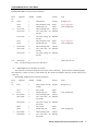
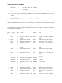
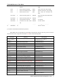
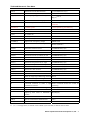
TDS-100M Ultrasonic Flow Meter
TDS-100M Ultrasonic Flowmeter
User Manual(Ver.18.0)
Beijing haifengyongjia science & technology co.,ltd.
Dalian hipeak instruments development co., ltd.
Dalian Hipeak Instruments Development Co.,Ltd.
1
TDS-100M Ultrasonic Flow Meter
Due to the busy development new generation of flow meters, we translated only the important and new
parts for the user manual of the TDS-100M ultrasonic flow meter/converter. Full translation will be
available later. We apology for the inconveniency caused by there is no proper English user manual.
Technical Manual for new versions TDS-100
1. Introduction
The new versions of TDS-100 ultrasonic flow meter/ultrasonic transmitter/ultrasonic heat meter are
developed based on our earlier version-7 and version-11 ultrasonic flow meter.
1. Must-knows about TDS-100M
Please the users must read the following paragraphs when you use TDS-100M for the first time
1. The setup of a TDS-100M ultrasonic flow converter needs one of the three tools. The first tool is a
parallel LCD and keypad module which can be connected to the 20 Pins port. The second tool is a
serial LCD and keypad module which can be connected to the RS232 port. The third one is a PC-based
software (under development), by means of the software, the parameters that TDS-100M needs to work
properly could be downloaded by use of the RS232 port on the PC. If your computer does not have a
RS232 port, you need to buy a USB-RS232 converter.
2. All setup parameter data are stored in the RAM memory temporally. Users need to solidify the
parameters, when setups are been finished, that is to store the parameter to the internal flash memory.
Go to Menu26, Select the option that says “make default paras” then pressing the ENT key will start
the progress of storing. If the current parameters are different with that in the flash memory, the system
will store your current parameters into the flash memory and then boot again. By doing so, the
parameters will always be get lost, even when both the power supply and the backup battery are
removed.
3. The zero point, that is the indicated flow under the situation of motionless liquid, has a great influence
over the linearity and accuracy of the flow meter. Users should try every possibility to perform the
Zero Setup that is located at Menu 42. Zero setup should always been performed under the condition of
motionless liquids. If Zero setup was been performed with motion of the liquid, you can use Menu 43
to restore to the original zero point. The zero point will be stored in the RAM memory temporally
when you use Menu 42. If you want to solidify the zero point, you need to perform Menu 26 “make
default paras” function again. If this step was omitted, the system will override the RAM zero point by
restoring the zero point that is stored in the flash memory with next power-on.
4. The internal calendar is the base of date accumulators. Incorrect date and time will cause messy records
with the date accumulators. Please the user check the calendar by input correct date and time. The
calendar runs relying on the backup battery when there is no 24VDC supply. When the battery voltage
is less than 2 volts, a new backup battery should be replaced with. Replacing the battery with a new
one should be performed with the 24VDC applied so that the accumulator data and calendar data will
not get lost.
Dalian Hipeak Instruments Development Co.,Ltd.
2
TDS-100M Ultrasonic Flow Meter
5. Please pay great attention to the power supply. The applied voltage should be in the range of +15V to
24VDC, or 15V to 20VAC. Avoid applying a 110VAC or 220VAC power forever, or the module will be
damaged.
6. Pay attention to the display located on Menu 48, which shows the points of lines for the linearity
correction function. 0 stands for shutting off the function. The default value is 0. Try to make sure that
value is 0 so as to avoid abnormal flow.
7. The latest calibrated data which are produced by performing the analog input or output calibration are
store in the RAM memory temporally. Users need to perform the M26 function to make these data be
solidified.
8. Use Menu 49 to check if there are inputs from the RS232 port with network application. If not, please
check protocol selection software switch located at Menu 63 and the serial port parameters options
located at Menu62. Select option 1 at Menu 63 for the MOSBUS RTU application. Select option 0 for
MODBUS ASCII and FUJI extended and Simple Water Meter protocols.
9. By a flash of the LED indicator for every 2 seconds, TDS-100M means the meter work properly. A
short flash for every second indicates no-signal or poor signal condition and a long flash for every
second shows the meter is performing a receiving gain adjusting.
2. Introduction to TDS-100M
(1) Development introduction
The TDS-100M is a compact, high performance general purpose ultrasonic flow meter module. The
design of the meter is intended to provide for users like system integrators and OEM users with a lowest
cost but of high performance flow meter. The development of the meter is based on a widely used flow
meter made by this company. The meter uses only one high performance MSP430 series microprocessor
made by Taxes Instruments.
This module can work alone without a LCD and Keypad module. The parameters that the flow meter
needed to work properly can be (1) setup by a parallel keypad module witch will be plugged onto the
parallel interface inside of the module, or by a serial keypad module witch will be plugged onto the
RS232C or RS485 port of the meter. (2) downloaded by use of a PC computer based software (the software
is under development now).
The transducers can be one the all kinds of the types made by this company, include the clamp-on type,
the insertion type, the PI- type and standard-pipe type. It can even use transducers by the users or the
transducers made by other company.
The module will satisfy the measurement requirement for most kind of liquids, such as water, sea
water, sew water and chemistry liquids. It can even measure pure paper pulp or fluids with higher density
suspend particles.
The module can be used alone as a flow meter. Users can even integrate a number of the modules into
a multi-channel flow meter that can measures up to several dozen of different pipes or a flow meter that has
higher accuracy by measures the same pipe with all the channels.
The low flow performance of this module is better compared with our previous flow meters. It can
measures a flow that is as low as 0.001m/S properly when the PI-transducers are used.
(2)Features
1. better than 1% accuracy, better than 0.2% repeatabilty.
2. 128 times of measurement and the revised software make the performance better and the indicated
flow more stable.
Dalian Hipeak Instruments Development Co.,Ltd.
3
TDS-100M Ultrasonic Flow Meter
3. RS232 and RS485 serial port
4. One or two analog inputs.
5. Optional 4-20mA analog output.
6. Two OCT output channels
7. Ability to measure sew water.
8. 4 kinds of different types of transducers can be used, addition with user-defined transducers.
9. The internal universal serial bus enables several output modules to be connected to it.
10. All the parameters can be solidify into the flash memory.
11. Several optional function module to be chosen to add to the main module.
12. 3 different kinds of communication protocol supported by the same time, include MODBUS.
13. Date totalizers that can record as much as 128 sets of data by day, 64 sets of data by month. All the
data can be retrieved by use of the MODBUS registers
14. 32 times of records of power-on and power-off data. Data can be read through MOBUS.
15. built-in data logger/printer, full programmable with what to be print ,the start time, interval, and
duration.
16. Programmable pulse width of OCT output.
17 Parallel interface for display and keypad.
18 plug-on-and-off display and keypad module can be connected to the serial port of the meter.
19 Almost the same menu arrangement make the users of previous version of flow meter very easy to
operate.
20 A fluid velocity threshold enables the identification of the kinds of fluid.
21. Digital inputs can be inputted by used of the analog inputs.
22. A full programmable built-in batch controller which can be started by key-pressing, inputs to the
analog inputs or through MODBUS protocol.
23. Power supply by 15VDC~24VDC/50mA or 15VAC~17VAC/50mA.
3. Menu Window Details
The flow meter user interface comprises about 100 independent windows. That are numbered by
M00,M01,M02……. M99,M+0,M+1 etc.
You do not need to remember all the menu windows. Just remember the most command used windows and
the proximate window numbers of some uncommonly used windows would be sufficient. You can always
use the going up and going down key to find the right window.
Note: 1 it is recommended to practice those menu windows on your flow meter while reading this chapter
for the sake of easier understanding.
2.To quickly switch to a menu window, simply press the ‘MENU’ key followed by the window
number (a two digit number). To move from one window to the next, use ‘UP’ or ‘Down’ keys.
Dalian Hipeak Instruments Development Co.,Ltd.
4
TDS-100M Ultrasonic Flow Meter
Menu
Window
No.
M00
M01
M02
M03
M04
M05
M06
M07
M08
M09
M10
M11
M12
M13
M14
M15
M16
M17
M18
M19
M20
Function
Display flow rate and NET totalizer
If the the net totalizer is turned off, the net totalizer value shown on the screen is the
value prior to its turn off
Select all totalizer unit in menu M31
Display flow rate, velocity
Display date time and POS(positive) totalizer
If the the positive totalizer is turned off, the positive totalizer value shown on the
screen is the value prior to its turn off
Display flow rate and NEG(negative) totalizer
If the the negative totalizer is turned off, the negative totalizer value shown on the
screen is the value prior to its turn off
Display date and time, flow rate. The date and time setting method is found in
MENU60
Display energy rate(instantaneous Caloric)and total energy (Caloric)
Display temperatures, inlet T1, outlet T2
Display analog inputs, AI3/AI4, current value and its corresponding temperature or
pressure or liquid level value
Display all the detailed error codes
Display working condition and system error codes. ‘R’ stands for normal, others refer
to Chapter for details.
Display today’s total NET flow
Window for entering the outer perimeter of the pipe
If pipe outer diameter is known, skip this menu and go to Menu 11to enter the outer
diameter
Window for entering the outer diameter of the pipe. Valid range:0 to 18000mm.
Note: you just need to enter either the outer diameter in M11 or the peripheral in M10
Window for entering pipe wall thickness
You may skip the menu and enter inner diameter in M13 instead.
Window for entering the inner diameter of the pipe
If pipe outer diameter and wall thickness are enter correctly, the inner diameter will be
calculated automatically, thus no need to change anything in the windown
Window for selecting pipe material
Standard pipe materials (no need to enter material sound speed ) include:
(0) carbon steel (1) stainless steel (2) cast iron
(3) ductile iron
(4)
copper
(5) PVC
(6) aluminum
(7) asbestos
(8) fiberglass (9) other( need to enter material sound speed in M15)
Window for entering the pipe material speed, only for non-standard pipe materials
Window for selecting the liner material, select none for pipes without any liner.
Standard liner materials(no need to enter the liner sound speed) include:
(1) Tar Epoxy
(2) Rubber
(3) Mortar
(4) Polypropylene
(5) Polystryol
(6)Polystyrene
(7) Polyester
(8) Polyethylene (9)
Ebonite
(10) Teflon
(11) Other (need to enter liner sound speed in M17)
Window for entering the non-standard liner material speed.
Window for entering the liner thickness, if there is a liner
Window for entering the ABS thickness of the inside wall of the pipe
Window for selecting fluid type
For standard liquids(no need to enter fluid sound speed) include:
(0) Water
(1) Sea Water
(2) Kerosene
(3) Gasoline
(4) Fuel oil
(5) Crude Oil
(6) Propane at -45C (7) Butane at 0C
(8)Other liquids(need to enter sound speed in M21 and viscosity in M22)
(9) Diesel
Oil
(10)Caster Oil
(11)Peanut Oil (12) #90 Gasoline (13) #93 Gasoline
Dalian Hipeak Instruments Development Co.,Ltd.
5
TDS-100M Ultrasonic Flow Meter
M21
M22
M23
M24
M25
M26
M27
M28
M29
(14) Alcohol (15) Hot water at 125C
Window for entering the the sound speed of non- standard liquid, used only when
option item 8 ‘Other’ is selected in M20
Window for entering the viscosity of the non-standard liquids, used only when option
item 8 ‘Other’ is selected in M20
Window for selecting transducer type, There are 22 types as following
0. Standard M
(The middle size)
1. Insertion Type C
2. Standard S
3. User Type
4. Standard B
5. Insertion Type B(45)
6. Standrad L
(The large size transducers)
7. JH-Polysonics
8. Standard-HS
(small size transducer for Handheld flow meter)
9. Standard-HM (middle size transducer for Handheld flow meter)
10. Standard-M1 (middle size transducer #1)
11. Standard-S1
(small size transducer #1)
12. Standard-L1
(large size transducer #1)
13. PI-Type
14. FS410
(middle size transducer for FUJI flow meter)
15. FS510
(large size transducer for FUJI flow meter)
16. Clamp-on TM-1 (Middle size transducer for other company)
17. Insertion TC-1 (for other company)
18. Calmp-on TS-1 (small size for other company)
19. Reserved
20. Clamp-on TL-1
(For other company)
21. Insertion TLC-1 (For other company)
If the user-type-transducer is selected, you need enter additional 4 user-type-wedge
parameters that describe the user transducers.
If the PI-type transducer is selected, you need enter additional 4 PI-type transducer
parameters that describe the PI-type transducers
Window for selecting the transducer mounting methods
Four methods can be selected:
(0) V-method (1) Z-method
(2) N-method (3) W-method
Display the transducer mounting spacing or distance
(1) A switch for the parameters in flash memory will be loaded when power is turned
on. The default option is that the parameters will be loaded. If this switch is not
turned on, the system will try to use the parameters in the system RAM, if these
parameters are ok, otherwise the system will load the parameters in flash
memory
(2) Function to store the current parameters into the flash memory, so that these
parameters will be solidified and will be loaded as the default parameters every
time when power is turned on.
Entry to store to or restore from the internal Flash memory, as many as 9 different pipe
parameter configurations
To save or load the current setup parameter, use the going up or going down keys to
change the address number, press ‘ENT’ key, and use going down or going up keys to
select to save to or load from the memory.
Entry to determine whether or not to hold (or to keep) the last good value when poor
signal condition occurs. YES is the default setup.
Entry to setup empty signal threshold. When the signal is less than this threshold, the
pipe is regarded as empty pipe, and the flow meter will not totalize flow.
This is based on the fact that, for most occasions, when pipe is empty, the transducer
would still receive signal, just smaller than normal, As a result, The flow meter would
show normal operation, which is not correct.
Make sure that the enter value must be less than the normal signal strength.
Dalian Hipeak Instruments Development Co.,Ltd.
6
TDS-100M Ultrasonic Flow Meter
M30
M31
M32
M33
M34
M35
M36
M37
M38
M39
M3.
M40
M41
M42
M43
M44
M45
M46
M47
M48
M49
M50
To make sure that, when much noisy signals are received, the flow meter will not
incorrectly totalize flow, there is also a ‘Q’ threshold should be entered in M.5
Window for selecting unit system. The conversion English to Metric or vice versa will
not affect the unit for totalizers.
Window for selecting flow rate unit system.
Flow rate can be in
0. Cubic meter
short for (m3)
1. Liter
(l)
2. USA gallon
(gal)
3. Imperial Gallon
(igl)
4. Million USA gallon
(mgl)
5. Cubic feet
(cf)
6. USA liquid barrel
(bal)
7. Oil barrel
(ob)
The flow unit in terms of time can be per day, per hour, per minute or per second. So
there are 32 different flow rate units in total for selection.
Window for selecting the totaliziers unit. Available units are the same as those in M31
Window for setting the totalizer multiplying factor
The multiplying factor ranges from 0.001 to 10000. Factory default is 1
Turn on or turn off the NET totalizer
Turn on or turn off the POS (positive) totalizer
Turn on or turn off the NEG(negative) totalizer
(1) Totalizer reset
(2) Restore the factory default settings parameters. Press the dot key followed by the
backspace key. Attention, It is recommended to make note on the parameters before
doing the restoration
Manual totalizer used for easier calibration. Press a key to start and press a key to stop
the manual totalizer.
Interface Language selection.
The selection could also be changed automatically by the system, if English LCD
display is used as the display device.
Setup for local segmental LCD display. Enter 0 or 1 for the non-auto-scan mode; Enter
2~39 for the auto-scan mode. In the auto-scan mode the display will automatically
scan displaying from 00 to the entered number of the local segmental LCD display.
Flow rate damper for a stable value. The damping parameter ranges form 0 to 999
seconds.
0 means there is no damping. Factory default is 10 seconds
Low flow rate (or zero flow rate) cut-off to avoid invalid accumulation.
Zero calibration/Zero point setup. Make sure the liquid in the pipe is not running while
doing the setup.
Clear the zero point value, and restore the solidified zero point value.
Set up a flow bias. Generally this value should be 0.
Flow rate scale factor. The default value is ‘1’.
Keep this value as ‘1’, when no calibration has been made.
Network address identification number. Any integer can be entered except 13(0DH,
carriage return), 10 (0AH, line feeding), 42 (2AH), 38, 65535.
Every set of the instrument in a network environment should have a unique IDN.
Please refer to the chapter for communication.
System locker to avoid modification of the system parameters.
If password is forgotten, you could send a command ‘LOCK0’ to the serial input to
unlock. Or you can write 0 to REGISTER49-50 under MODBUS protocol.
Entry to linearity correcting data inputs. By using of this function, the non-linearity of
flow meter will be corrected. Correcting data shall be obtained by careful calibration.
Displays the input contents for the serial port.
By checking the displays, you can know if the communication is ok.
Switches for the built-in data logger. There are as many as 22 different items can be
Dalian Hipeak Instruments Development Co.,Ltd.
7
TDS-100M Ultrasonic Flow Meter
M51
M52
M53
M54
M55
M56
M57
M58
M59
M60
M61
M62
M63
M64
M65
chosen. To turn the this function, select ‘YES’ the system will ask for selecting the
items. There are 22 items available. Turn on all those items you want to output
Window to setup the time of scheduled output function (data logger, or
Thermo-printer). This includes start time, time interval and how many times of output.
When a number great than 8000 entered for the times of output, It means the output
will be keeping always. The minimum time interval is 1 second and the maximum is
24 hours.
Data logging direction control.
(1) If ‘Send to RS485’ is selected, all the data produced by the data logger will be
transmitted out through the RS-232/RS485 interface
(2) If ‘To the internal serial BUS‘ is selected, the data will be transmitted to the
internal serial bus which allows a thermal printer, or a 4-20mA analog output
module, to be connected to it.
Display analog inputs, AI5, current value and its corresponding temperature or
pressure or liquid level value.
Pulse width setup for the OCT (OCT1) output. Minimum is 6 mS, maximum is 1000
mS
Select analog output (4-20mA current loop, or CL) mode. Available options:
(0) 4-20mA output mode (setup the output range from 4-20mA)
(1) 0-20mA output mode (setup the output range from 4-20mA, This mode can only be
used with Version-15 flow meter)
(2) Serial port controls 0-20mA
(3) 4-20mA corresponding fluid sound speed
(4) 20-4-20mA mode
(5) 0-4-20mA mode (can only be used with Version-15 flow meter)
(6)20-0-20mA mode(can only be used with Version-15 flow meter)
(7) 4-20mA corresponding flow velocity
(8)4-20mA corresponding heat flow rate
4mA or 0mA output value,
Set the value which corresponds to 4mA or 0mA output current (4mA or 0mA is
determined by the setting in M55)
20mA output value,
Set the value which corresponds to 20mA output current
Current loop verification
Check if the current loop is calibrated correctly.
Display the present output current of current loop circuit.
Setup system date and time. Press ENT for modification. Use the dot key to skip the
digits that need no modification.
Display Version information and Electronic Serial Number (ESN) that is unique for
each flow meter.
The users may employ the ESN for instrumentation management
RS-232/RS485 setup. All the devices connected with flow meter should have matched
serial configuration.
The following parameters can be configured: Baud rate (300 to 19200 bps), parity, data
bits (always is 8), stop bits
Select communication protocol.
Factory default is ‘MODBUS ASCII+TDS7’.this is a mode for MODBUS-ASCII,
Meter-BUS, TDS7-Fuji Extended Protocol, Huizhong’s various protocols.
If you are going using MODBUS-RTU you have to select ‘ MODBUS_RTU’.
AI3 value range.
Used to enter temperature/pressure values that are corresponding to 4mA and 20mA
input current. The display values have no unit, so that they can present any physical
parameter.
AI4 value range.
Used to enter temperature/pressure values that are corresponding to 4mA and 20mA
input current.
Dalian Hipeak Instruments Development Co.,Ltd.
8
TDS-100M Ultrasonic Flow Meter
M66
M67
M68
M69
M70
M71
M72
M73
M74
M75
M76
M77
M78
M79
AI5 value range.
Used to enter temperature/pressure values that are corresponding to 4mA and 20mA
input current.
Windows to setup the frequency range (lower and upper limit) for the frequency output
function. Valid range is 0Hz-9999Hz. Factory default value is 0-1000 Hz.
For Version-12, Version-13, Version-14 flow meters, you need a hardware module,
which shall be plugged to the Serial Expanding Bus, for the frequency output function.
Please remember to order the module if you need frequency output function.
For Version-15 flow meter, you need to indicate on your orders that you need the
frequency function; Otherwise you will get a flow meter which has no frequency
output circuits.
Window to setup the minimum flow rate value which corresponds to the lower
frequency limit of the frequency output.
Windows to setup the maximum flow Rate value that corresponds to the upper
frequency limit of the frequency output.
LCD display backlight control. The entered value indicates how many seconds the
backlight will be on with every key pressing. If the enter value is great than 50000
seconds, It means that the backlight will always keeping on.
LCD contrast control. The LCD will become darker or brighter when a value is
entered.
Working timer. It can be cleared by pressing ENT key, and then select YES.
Window to setup the lower limit of flow rate for Alarm#1.
When the flow rate is below the set value, Alarm#1 equals ‘on’
Window to setup the upper limit of flow rate for Alarm#1.
When the flow rate is above the set value, Alarm#1 equals ‘on’
There are two alarms in the flow meter, and every alarm can be pointed to alarm output
devices such as the BUZZER or OCT output or RELAY output. For example, if you
want the Alarm#1 be to output by the OCT circuit, you need to set M78 at selection
item 6.
Window to setup the lower limit of flow rate for Alarm#2.
Window to setup the upper limit of flow rate for Alarm#2.
Buzzer setup.
If a proper input source is selected, the buzzer will beep when the trigger event occurs.
The available trigger sources are:
0. No Signal
1. Poor Signal
2. Not Ready(No*R) 3. Reverse Flow
4. AO Over 100%
5. FO Over 120%
6. Alarm #1
7. Reverse Alarm #2
8. Batch Control
9. POS Int Pulse
10.NEG Int Pulse
11.NET Int Pulse
12.Energy POS Pulse 13.Energy NEG Pulse
14.Energy NET Pulse 15.MediaVel=>Thresh 16.MediaVelo<Thresh
17.ON/OFF viaRS232
18.Key Stroking ON 19.Disable BEEPER
OCT (Open Collect Transistor Output)/OCT1 setup
By selecting a proper input source, the OCT circuit will close when the trigger event
occurs. The available trigger sources are:
0. No Signal
1. Poor Signal
2. Not Ready(No*R) 3. Reverse Flow
4. AO Over 100%
5. FO Over 120%
6. Alarm #1
7. Reverse Alarm #2
8. Batch Control
9. POS Int Pulse
10.NEG Int Pulse
11.NET Int Pulse
12.Energy POS Pulse 13.Energy NEG Pulse
14.Energy NET Pulse 15.MediaVel=>Thresh 16.MediaVelo<Thresh
17.ON/OFF viaRS232 18.Oct Not Using
When the OCT circuit is close, it will draw current. The maximum current shall not be
over 100mA. When the OCT circuits is open, there will be no current output or draw
in. Attention: the maximum voltage applied to OCT can not be over 80 volts or the
circuit will be damaged
Relay or OCT2 setup
By selecting a proper input source, the hardware will close when the trigger event
Dalian Hipeak Instruments Development Co.,Ltd.
9
TDS-100M Ultrasonic Flow Meter
occurs
Note. In order to make the user interface compatible with the future tds10, the name
RELAY was used other than OCT2, but in fact it is an OCT output.
The available trigger sources are:
0. No Signal
1. Poor Signal
2. Not Ready(No*R) 3. Reverse Flow
4. AO Over 100%
5. FO Over 120%
6. Alarm #1
7. Reverse Alarm #2
8. Batch Control
9. POS Int Pulse
10.NEG Int Pulse
11.NET Int Pulse
12.Energy POS Pulse 13.Energy NEG Pulse
14.Energy NET Pulse 15.MediaVel=>Thresh 16.MediaVelo<Thresh
17.ON/OFF viaRS232 18.Disable Relay
M80
M81
M82
M83
M84
M85
M86
M87
M88
M89
M90
Window for selecting the trig signal for the built-in batch controller. Available trig
sources:
0. Key input
(press Ent key to start the batch controller)
1. Serial port
2. AI3 rising edge
(when AI3 receives 2mA or more current)
3. AI3 falling edg
(when AI3 stop receiving 2mA or more current)
4. AI4 rising edge
(when AI3 receives 2mA or more current)
5. AI4 falling edge
(when AI3 stop receiving 2mA or more current)
6. AI5 rising edge
(when AI3 receives 2mA or more current)
7. AI5 falling edge
(when AI3 stop receiving 2mA or more current)
For the input analog current signal, 0 mA indicates “0”, 4mA or more indicates ‘1’.
The built-in batch controller
Set the flow batch value(dose)
The internal output of the batch controller can be directed either to the OCT or the
RELAY output circuits.
M81 and M80 should be used together to configure the batch controller.
Note: Because the measuring period is 500mS, the flow for every dos should be
keeping at 60 seconds long to get a 1% dose accuracy.
View the dayly, monthly and yearly flow totalizer and thermal energy totalizer value.
The totalizer values and errors for the last 64 days, 32 last 32 months and last 2 years
are stored in the RAM memory, To view them, use the ‘ENT’ and ‘UP’ ‘Down’ keys.
Automatic Amending Function for automatic offline compensation.
Select ‘YES’ to enable this function, select ‘NO’ to disable it.
When the function is enabled, The flow meter will estimate the average flow
uncounted (or ‘lost’) during the offline session and add the result to the totalizer.
The estimation of the uncounted flow is made by computing the product of the offline
time period and the average flow rate, which is the average of the flow rate before
going offline and the one after going on line.
Set the thermal energy unit: GJ or KC.
Select temperature sources
0. from T1,T2 (factory default)
1. from AI3,AI4
Select the Specific Heat Value.
Factory default is ‘GB’. Under this setting, the flow meter will calculate the enthalpy
of water based on the international standard.
If the fluid is other than water, you should select option ‘1. Fixed Specific Heat’, and
enter the specific heat value of the fluid.
Turn on or turn off the Energy totalizer.
Select thermal energy totalizer multiplying factor.
Factory default is ‘1’.
1. Display the temperature difference
2. Window for entering the lowest temperature difference.
Display signal strengths S (one for upstream and one for downstream), and signal
quality Q value.
Signal strength is presented by 00.0 to 99.9, the bigger the value, the bigger the signal
Dalian Hipeak Instruments Development Co.,Ltd.
10
TDS-100M Ultrasonic Flow Meter
M91
M92
M93
M94
M95
M96
M97
M98
M99
M+0
M+1
M+2
M+3
M+4
M+5
M+6
M+7
M+8
M+9
M.2
strength will be, and more reliable readings will be made.
Q value is presented by 00 to 99, the bigger the better. It should at least be great than
50 for normal operations.
Displays the Time Ratio between the Measured Total Transit Time and the Calculated
time. If the pipe parameters are entered correctly and the transducers are properly
installed, the ratio value should be in the range of 100±3%. Otherwise the entered
parameters and the transducer installation should be checked.
Displays the estimated fluid sound velocity. If this value has an obvious difference
with the actual fluid sound speed, pipe parameters entered and the transducer
installation should be checked again.
Displays total transit time and delta time(transit time difference)
Displays the Reynolds number and the pipe factor used by the flow rate measurement
program. Pipe factor is calculated based on the ratio of the line-average velocity and
the cross-section average velocity.
(1) Display the positive and negative energy totalizers
(2) Upon entering this window, the circular display function will be started
automatically. The following windows will be displayed one by one, each window will
stay
for
8
seconds:
M95>>M00>>M01>>M02>>M02>>
M03>>M04>>M05>>M06>>M07>>M08>>M90>>M91>>M92>>
M93>>
M94>>M95. This function allows the user to visit all the important information
without any manual action.
To stop this function, simply press a key. Or switch to a window other than M95.
This is not a window but a command for the thermal printer to advance 5 lines of
paper.
This is not a window but a command to print the pipe parameters.
By default, the produced data will be directed to the internal serial bus (thermal
printer). You can also direct those data to the serial communication port.
This is not a window but a command to print the diagnostic information.
By default, the produced data will be directed to the internal serial bus (thermal
printer). You can also direct those data to the serial communication port.
This is not a window but a command to copy the current display window. By default,
the produced data will be directed to the internal serial bus (thermal printer). You can
also direct those data to the serial communication port.
By use of the window copying function, you can hardcopy very window displaying
manually by switching windows, or you can obtain the window displaying data by
communication.
Browse the 32 recorded instrument power-on and power-off date and time with the
flow rate at the time of power on and off
Displays the total working time of the flow meter.
When the backup battery is removed, the total working time will be reset to zero.
Displays the last power-off date and time
Displays the last power-off flow rate
Displays how many times of has been powered on and powered off.
A scientific calculator for the convenience of field working.
All the values are in single accuracy.
The calculator can be used while the flow meter is conducting flow measurement.
Water density and PT100 temperature can also be found in this function.
Set fluid sound speed threshold
Whenever the estimated sound speed (displayed in M92) exceeds this threshold, an
alarms signal will be generated and can transmitted to BUZZER or OCT or RELAY.
This function can used to produce an alarm or output when fluid material changes.
Displays total flow for this month(only for the time past)
Displays total flow for this year(only for the time past)
Display the not-working total time in seconds. The total failure timer will also include
the time when power off, if the back-up battery is applied.
Entry to solidify the zero point. Password protected.
Dalian Hipeak Instruments Development Co.,Ltd.
11
TDS-100M Ultrasonic Flow Meter
M-0
M-1
M-2
M-3
M-4
M-5
M-6
M-7
M-8
M-9
M-A
Setup the Q value threshold.
If the present Q is below this threshold, flow rate will be set to 0.
This function is useful when flow meter is installed in noisy environment or on airy
pipes.
The maximum flow rates for today and this month.
Serial port tester with CMM command output for very second.
Entry to hardware adjusting windows only for the manufacturer
4-20mA output adjustment
4mA calibration for AI3 input
20mA calibration for AI3 input
4mA calibration for AI4 input
20mA calibration for AI4 input
4mA calibration for AI5 input
20mA calibration for AI5 input
Lower Temperature Zero setup for the PT100
Higher Temperature Zero setup for the PT100
Temperature Calibration at 50℃
M-B
Temperature Calibration at 84.5℃
M.5
M.8
M.9
Note 1.windows in Red are new to our older version of flow meter
2. windows in Blue are energy related windows
3. the term totalizer is also called accumulator.
4. Protocols
§4.1
TDS-100M has an non-isolated serial ports, RS485
TDS-100M can support three different communication protocols at the same time, that is MODBUS,
the Fuji Extended Protocol and the Easy-to-Use Water Meter Protocol
MODBUS is a very commonly used industrial protocol. Both the RTU and the ASCII format of
MODBUS can be supported
the Fuji Extended Protocol is developed based on the protocol used in a Japanese ultrasonic flow
meter. The extended protocol is compatible with that of Version 7 flow meter made by Hipeak.
The Easy-to-Use Water Meter Protocol is compatible with the water meters made by Hipeak and the
water meters made by Huizhong Instruments.
TDS-100M can even be used as a sample RTU terminal. The 4-20mA output in the TDS-100M can be
used to open an analog proportional valve; The OCT output can be used to control the turn-on and turn-off
of other devices such as a pump. The analog input can be used to input pressure or temperatures signals.
That the hardware allows a MODEM to be connected directly to the RS232 port will make it very easy
to setup a flow SCADA by means of PTN. While with the RS485 port, TDS-100M can be directly
connected to a network based on RS485 bus. By use of a GSM module, flow data can be obtained by use of
a mobile phone.
There is a programmable device address (or ID number) located at window M46 to make the flow
meter be easily used in a SCADA system. If there are more than two flow meters be used in a network, the
Dalian Hipeak Instruments Development Co.,Ltd.
12
TDS-100M Ultrasonic Flow Meter
prefix W should be used before every command.
The data link can be RS232C (0-15 meters) or RS485 (0-1000meters) when the distance is short. When
the distance is over 1 km, the data link can be a kind of current loop, radio, MODEM, GSP or GPRS.
When TDS-100M is used in a network, all the parameters of the flow meter can be programmed
through the network, except the device address that needs the keypad.
At most occasions, data should be obtained by polling the flow mete with a command, the flow meter
will respond with what the master asks.
The TDS-100M has a special command sets to facilitate the use of the flow meter in a GSM network.
§4.2 The MODBUS protocol
Both the two formats of the MODBUS protocol can be supported.
A software switch located at the window number 63(shorted as M63 after) select MODBUS-ASCII or
MODBUS-RTU will be in functioning.
The default option is MODBUS-ASCII format.
TDS-100M can only support MODBUS functions code 3 and code 6, i.e. reading registers and writing
a register.
For example, reading the registers from REG0001 to REG0010 in the unit #1 (ultrasonic flow meter)
under the MODBUS-RTU format, the command could be as following
01
03
00
00
00
0A
C5
CD
(hex)
Unit Function
start REG
Numbers of REGs
Check-sum
While under the MODBUS-ASCII format, the command could be
:01030000000AF2(CR and LF)
Details about the standard MODBUS protocol will not be studied in this manual, please the users find
them on other related materials.
By default, the RS232/RS485 will be setup with 9600,none,8,1(9600bd,none parity,8 data bits, 1
stop bit)
§4.2.1
MODBUS REGISTERS TABLE
MODBUS REGISTERS TABLE for TDS-100M
(please take notice the difference with the water meter MODBUS table)
REGISTE
R
0001-0002
0003-0004
0005-0006
0007-0008
0009-0010
NUMBE
R
2
2
2
2
2
VARIABLE NAME
FORMAT
NOTE
Flow Rate
Energy Flow Rate
Velocity
Fluid sound speed
Positive accumulator
REAL4
REAL4
REAL4
REAL4
LONG
REAL4 is a format of
Singular
IEEE-754
number, also called
FLOAT
Long integer, lower
byte first
0011-0012
0013-0014
2
2
Positive decimal fraction
Negative accumulator
REAL4
LONG
Dalian Hipeak Instruments Development Co.,Ltd.
13
TDS-100M Ultrasonic Flow Meter
0015-0016
0017-0018
0019-0020
0021-0022
0023-0024
0025-0026
0027-0028
0029-0030
0031-0032
0033-0034
0035-0036
0037-0038
0039-0040
0041-0042
0043-0044
0045-0046
0047-0048
0049-0050
2
2
2
2
2
2
2
2
2
2
2
2
2
2
2
2
2
2
Negative decimal fraction
Positive energy accumulator
Positive energy decimal fraction
Negative energy accumulator
Negative energy decimal fraction
Net accumulator
Net decimal fraction
Net energy accumulator
Net energy decimal fraction
Temperature #1/inlet
Temperature #2/outlet
Analog input AI3
Analog input AI4
Analog input AI5
Current input at AI3
Current input at AI3
Current input at AI3
System password
REAL4
LONG
REAL4
LONG
REAL4
LONG
REAL4
LONG
REAL4
REAL4
REAL4
REAL4
REAL4
REAL4
REAL4
REAL4
REAL4
BCD
In unit mA
In unit mA
In unit mA
Writable 。 00H for
0051
1
Password for hardware
BCD
unlock
Writable。“A55Ah” for
BCD
unlock
Writable。6 Bytes of
0053-0055
3
Calendar (date and time
BCD
stands
SMHDMY,lower byte
0056
1
Day+Hour for Auto-Save
BCD
first
Writable。For example
0512H
stands
Auto-save on 12:00 on
5th。0012H for 12:00
on everyday。
0059
0060
0061
0062
0062
0072
0077-0078
0079-0080
0081-0082
0083-0084
0085-0086
0087-0088
0089-0090
1
1
1
1
1
1
2
2
2
2
2
2
2
Key to input
Go to Window #
LCD Back-lit lights for
Times for the beeper
Pulses left for OCT
Error Code
PT100 resistance of inlet
PT100 resistance of outlet
Total travel time
Delta travel time
Upstream travel time
Downstream travel time
Output current
INTEGER
INTEGER
INTEGER
INTEGER
INTEGER
BIT
REAL4
REAL4
REAL4
REAL4
REAL4
REAL4
REAL4
Writable
Writable。
Writable 。 In
unit
second
Writable。Max 255
Writable。Max 65535
16bits, see note 4
In unit Ohm
In unit Ohm
In unit Micro-second
In unit Nino-second
In unit Micro-second
In unit Micro-second
In unit mA
Dalian Hipeak Instruments Development Co.,Ltd.
14
TDS-100M Ultrasonic Flow Meter
0092
1
0093
0094
0096
0097-0098
1
1
1
2
0099-0100
0101-0102
0103-0104
0105-0106
0105-0106
0113-0114
0115-0116
0117-0118
0119-0120
0121-0122
0123-0124
0125-0126
0127-0128
0129-0130
0131-0132
0133-0134
0135-0136
0137-0138
0139-0140
0141-0142
0143-0144
0145-0146
0147-0148
0158
0165-0166
0173-0174
0175-0176
0181-0182
0183-0184
0185-0186
0187-0188
0189-0190
0191-0192
0221-0222
2
2
2
2
2
2
2
2
2
2
2
2
2
2
2
2
2
2
2
2
2
2
2
1
2
2
2
2
2
2
2
2
2
2
Working step and
Signal Quality
INTEGER
Upstream strength
Downstream strength
Language used in user interface
Rate of measured travel time by
calculated.
Reynolds number
Pipe Reynolds factor
Working Timer
Total working time
Total power on-off time
Net accumulator
Positive accumulator
Negative accumulator
Net energy accumulator
Positive energy accumulator
Negative energy accumulator
Flow for today
Flow for this month
Manual accumulator
Manual accumulator decimal fraction
Batch accumulator
Batch accumulator decimal fraction
Flow for today
Flow for today decimal fraction
Flow for this month
Flow for this month decimal fraction
Flow for this year
Flow for this year decimal fraction
Current window
Failure time
Current output frequency
Current output with 4-20mA
Temperature difference
Lost flow
Clock coefficient
Total time for Auto-Save
POS flow for Auto-Save
Flow rate for Auto-Save
Inner pipe diameter
INTEGER
INTEGER
INTEGER
REAL4
REAL4
REAL4
LONG
LONG
LONG
REAL4
REAL4
REAL4
REAL4
REAL4
REAL4
REAL4
REAL4
LONG
REAL4
LONG
REAL4
LONG
REAL4
LONG
REAL4
LONG
REAL4
INTEGER
LONG
REAL4
REAL4
REAL4
REAL4
REAL4
REAL4
REAL4
REAL4
REAL4
The high byte is the
step and low for
signal quality,range
00-99,the larger the
better.
Range 0-2047
Range 0-2047
0 : English,1:Chinese
Normal 100+-3%
unsigned,in second
unsigned,in second
unsigned
In Cubic Meter,float
In Cubic Meter,float
In Cubic Meter,float
In Cubic Meter,float
In Cubic Meter,float
In Cubic Meter,float
In Cubic Meter,float
In Cubic Meter,float
In unit second
Should less than 0.1
Time to save by 0056
Time to save by 0056
Time to save by 0056
In millimeter
Dalian Hipeak Instruments Development Co.,Ltd.
15
TDS-100M Ultrasonic Flow Meter
0229-0230
0231-0232
0233-0234
0257-0288
0289
2
2
2
32
1
Upstream delay
Downstream delay
Calculated travel time
LCD buffer
LCD buffer pointer
REAL4
REAL4
REAL4
BCD
INTEGER
In microsecond
In microsecond
In microsecond
0311
0313
1437
1438
1439
1440
1441
1442
1451
1521
1523
1524
2
2
1
1
1
1
1
1
2
2
1
1
Worked time for today
Worked time for this month
Unit for flow rate
Unit for energy totalizer
Multiplier for accumulator
Multiplier for energy accumulator
Unit for energy flow rate
Device address
User scale factor
Manufacturer scale factor
Multiplier for accumulator
Multiplier for energy accumulator
LONG
LONG
INTEGER
INTEGER
INTEGER
INTEGER
INTEGER
INTEGER
REAL4
REAL4
INTEGER
INTEGER
Unsigned, in seconds
Unsigned, in seconds
See note 5
0=GJ 1=Kcal
Range 0~7,see note 1
Range 0~10,see note 1
0=GJ/h , 1=Kcal/h
Read only
Same address with
water meter, but has
different meaning
1525
1
Unit for energy accumulator
INTEGER
1529
2
Electronic serial number
BCD
High byte first
Note :(1) The internal accumulator is been presented by a LONG number for the integer part
together with a REAL number for the decimal fraction. In general uses, only the integer part needs to be
read. Reading the fraction can be omitted. The final accumulator result has a relation with unit and
multiplier. Assume N stands for the integer part (for the positive accumulator, the integer part is the content
of REG 0009, 0010, a 32-bits signed LONG integer,), Nf stands for the decimal fraction part (for the
positive accumulator, the fraction part is the content of REG 0011, 0012, a 32-bits REAL float number,), n
stands for the flow multiplier (REG 1439).
then
The final positive flow rate=(N+Nf ) ×10n-3 (in unit decided by REG 1439)。
The meaning of REG 1439 which has a range of 0~7 is as following:
0 cubic meter
(m3)
1 liter
(L)
2 American gallon
(GAL)
3 imperial gallon
(IGL)
4 American million gallon (MGL)
5 Cubic feet
(CF)
6 American oil barrel
(1 barrel =42gallon) (OB)
7 Imperial oil barrel
(IB)
While
The energy flow rate =(N+Nf )×10n-4(unit decided by REG 1440)
。
(2) Other variables are not given here. Call us if you have a need.
Dalian Hipeak Instruments Development Co.,Ltd.
16
TDS-100M Ultrasonic Flow Meter
(3) Please note there are many of the data that is not applicable for the non-energy measurement users.
These none-energy-related registers only serves for the intension of only one unique register table provided
both with flow meter and energy meat.
(4)Meaning in error code
Bit0 no received signal
Bit1 low received signal
Bit2 poor received signal
Bit3 pipe empty
Bit4 hardware failure
Bit5 receiving circuits gain in adjusting
Bit6 frequency at the frequency output over flow
Bit7 current at 4-20mA over flow
Bit8 RAM check-sum error
Bit9 main clock or timer clock error
Bit10 parameters check-sum error
Bit11 ROM check-sum error
Bit12 temperature circuits error
Bit13 reserved
Bit14 internal timer over flow
Bit15 analog input over range
Please try to override these energy-related bits first when in flow-only measurement,(5)Unit code
for flow rate
0
Cubic meter/second
1
Cubic meter /minute
2
Cubic meter /hour
3
Cubic meter /day
4
liter/second
5
liter /minute
6
liter /hour
7
liter /day
8
American gallon/second
9
American gallon /minute
10
American gallon /hour
11
American gallon /day
12
Imperial gallon/second
13
Imperial gallon /nimute
14
Imperial gallon /hour
15
Imperial gallon /day
16
American
17
American
18
American million
19
American
million
gallon/second
million
gallon
/minute
gallon
/hour
million
gallon/day
20
Cubic feet/second
21
Cubic feet/minute
22
Cubic feet/hour
23
Cubic feet/day
24
American oil barrel/second
25
American oil barrel/minute
26
American oil barrel/hour
27
American oil barrel/day
28
Imperial oil barrel/second
25
Imperial oil barrel/minute
26
Imperial oil barrel/hour
27
Imperial oil barrel/day
§4.2.2 REGISTER
TABLE for the DATE accumulators
(1) REGISTER for accumulators by day
Accumulator data for every past day are stored in a loop queue. Every day has 16 bytes of data and
there are 128 days in total. The current pointer which has a range of 0~127 for the day is in REG 0162. if
the pointer is decreased by 1 when the pointer is 0, then new pointer value will be 127. Assume REG 0162=
1, the data for yesterday are in REG 3337~3344, the data for day before yesterday are in REG3329-3336,
and the data for day of 2 days ago are in REG 4345-4352.
Dalian Hipeak Instruments Development Co.,Ltd.
17
TDS-100M Ultrasonic Flow Meter
REGISTER TABLE for the DAY accumulators
block
No
n/a
0
Register
0162
3329
3330
3331-3332
3333-3334
3335-3336
1
3337
3338
3339-3340
3341-3342
3343-3344
。。
。。 。。
。。
。。
。。
。。
127
number
variable
1
1
1
2
2
Data pointer
Day and Error Code
Month and year
Total working time
Net total flow for
the day
2
Net total energy for
the day
1
Day and Error Code
1
Month and year
2
Total working time
2
Net total flow for
the day
2
Net total energy for
the day
。。
。。
。。 。。
。。
。。
。。
。。
。
。。。
4345-4352
8
note:see the meaning of the error code above.
format
note
Integer
BCD
BCD
LONG
REAL4
Range:0~127
Day in high byte
Year in high byte
REAL4
BCD
BCD
LONG
REAL4
Day in high byte
Year in high byte
REAL4
。。
。。
。。
。。
。。
。。
。。
。。
。
。。
。。
。。
。。。
Data block No.127
(2) REGISTER for accumulators by month
The structure of month accumulator is the same as that of the day,please refer to related paragraph。
The difference is there are only 63 data blocks for the month accumulator, and day variable always has a
value of 0.
REGISTER TABLE for the month accumulators
block
Register
number variable
format
Note
No
n/a
0163
1
Data pointer for the Integer
Range: 0~63
month
2817
1
Error Code
BCD
2818
1
Month and year
BCD
Year in high byte
0
2819-2820
2
Total working time
LONG
2821-2822
2
Net total flow for REAL4
the month
2823-2824
2
Net total energy for REAL4
the month
2825
1
Error Code
BCD
2826
1
Month and year
BCD
Year in high byte
1
2827-2828
2
Total working time
LONG
2829-2830
2
Net total flow for REAL4
the month
Dalian Hipeak Instruments Development Co.,Ltd.
18
TDS-100M Ultrasonic Flow Meter
2831-2832
。。
。。 。。
。。
。。
。。
。。
Net total energy for
the month
。。
。。
。。 。。
。。
。。
。。
。。
。
。。。
63
8
3321-3328
2
REAL4
。。
。。
。。
。。
。。
。。
。。
。。
。
。。
。。
。。
。。。
Data block No. 63
(3) There is no direct data for the year, data for the year could be conducted from the data of the
months.
§4.2.3
REGISTERs for power-on and power-off
With every t power-on and power-off, the new generation flow meter will record data about the time,
duration, statue byte and the flow rate into a data block. Every data block consists 32 bytes of data. There
are as many as 32 blocks of data can be recorded, for 32 times of power-on and 32 times of power-off. The
data blocks are in a structure of loop queue. The 33rd data block will override the first block by default. The
location of the current block is presented in the data pointer. The current power-on data block is pointed by
the decease by 1 of the pointer.
MODBUS registers table for the power-on and power-off.
block
Register
No. variable
format
Note
No
n/a
0164
1
Pointer
Integer
Range:0~31
4353
1
Power-on second and BCD
Second in low byte, minute in
minute
high
0
4354
1
Power-on hour and day
BCD
Hour in low byte, day in high
4355
1
Power-on month and year
BCD
Month in low byte, year in high
4356
1
Power-on error code
BIT
B15 stand for corrected lost
flow.
4357
1
Power-off second and BCD
Second in low byte, minute in
minute
high
4358
1
Power-off hour and day
BCD
Hour in low byte, day in high
4359
1
Power-off month and year
BCD
Month in low byte, year in high
4360
1
Power-off error code
BIT
B15 stand for corrected lost
flow
4361-4362
2
Flow rate when power on
REAL4
Flow rate after 60 seconds when
power on
4363-4364
2
Flow rate when power off
REAL4
4365-4366
2
Time duration when off
LONG
In seconds
4367-4368
2
Corrected lost flow when REAL4
In cubic meters
off
4369
1
Power-on second and BCD
Second in low byte, minute in
minute
high
1
4370
1
Power-on hour and day
BCD
Hour in low byte, day in high
4371
1
Power-on month and year
BCD
Month in low byte, year in high
4372
1
Power-on error code
BIT
B15 stand for corrected lost
flow.
4373
1
Power-off second and BCD
Second in low byte, minute in
Dalian Hipeak Instruments Development Co.,Ltd.
19
TDS-100M Ultrasonic Flow Meter
4374
4375
4376
1
1
1
minute
Power-off hour and day
Power-off month and year
Power-off error code
4377-4378
2
Flow rate when power on
REAL4
4379-4380
4381-4382
4383-4384
2
2
2
Flow rate when power off
Time duration when off
Corrected lost flow when
off
REAL4
LONG
REAL4
In seconds
In cubic meters
。。
。。
。。
。。
。。
。。
。。
。。
。
。。
。。
。。
。。。
。。
。。 。。
。。
。。
。。。 。。。
31
4849-4864
BCD
BCD
BIT
high
Hour in low byte, day in high
Month in low byte, year in high
B15 stand for corrected lost
flow
Flow rate after 60 seconds when
power on
The 32nd block
16
§4.3 The FUJI extended communication protocol
TDS-100M uses the compatible FUJI extended communication protocol with our previous Version7
ultrasonic flow meter, except the commands in red lines in the following table.
Command
DQD(cr) note 0
Meaning
Data format
Returns flow rate per day
±d.ddddddE±dd(cr) note 1
DQH(cr)
Returns flow rate per hour
±d.ddddddE±dd(cr)
DQM(cr)
Returns flow rate per minute
±d.ddddddE±dd(cr)
DQS(cr)
Returns flow rate per second
±d.ddddddE±dd(cr)
DV(cr)
Returns fluid velocity
±d.ddddddE±dd(cr)
DI+(cr)
Returns positive totalizer
DI-(cr)
Returns negative totalizer
±dddddddE±d(cr)
DIN(cr)
Returns net totalizer
±dddddddE±d(cr)
DIE(cr)
Returns net energy totalizer
±dddddddE±d(cr)
DIE+(cr)
Returns positive energy totalizer
±dddddddE±d(cr)
DIE-(cr)
Returns negtive energy totalizer
±dddddddE±d(cr)
DIT(cr)
Returns net total flow for today
±dddddddE±d(cr)
DIM(cr)
Returns net total flow for this month
±dddddddE±d(cr)
DIY(cr)
Returns net total flow for this year
±dddddddE±d(cr)
DID(cr)
Returns the ID number/address
ddddd(cr)
E(cr)
Return energy flow rate per hour
±d.ddddddE±dd(cr)
DL(cr)
Returns the signal strength
UP:dd.d,DN:dd.d,Q=dd(cr)
DS(cr)
Returns percentage of AO output
±d.ddddddE±dd(cr)
DC(cr)
Returns current error code
Note 3
DA(cr)
OCT and RELAY output
±dddddddE±d(cr)note 2
5 bytes long
TR:s,RL:s(cr)note 4
Dalian Hipeak Instruments Development Co.,Ltd.
20
TDS-100M Ultrasonic Flow Meter
DT(cr)
Returns the current date and time
yy-mm-dd,hh:mm:ss(cr)
Time@TDS1=(cr)
Set date and time yy-mm-dd,hh:mm:ss
M@(cr)
Mimic key input. @ presents a key
LCD(cr)
Returns current window display
LOCK0(cr)
Unlock the system
Has nothing to do with the original
password.
LOCK1(cr)
Lock the system
Can be opened by press ENT key
MENUXX(cr)
Go to window XX
C1(cr)
OCT turns on
C0(cr)
OCT turns off
R1(cr)
RELAY(OCT2) turns on
R0(cr)
RELAY(OCT2)turns off
FOdddd(cr)
Output n Hz at frequency output
AOa(cr)
Output a mA current at AO output
BA1(cr)
Return the resistance for T1
±d.ddddddE±dd(cr)(lf)
BA2(cr)
Return the resistance for T2
±d.ddddddE±dd(cr)(lf)
BA3(cr)
Returns the current (0~20mA) at AI3
±d.ddddddE±dd(cr)(lf)
BA4(cr)
Returns the current (0~20mA) at AI4
±d.ddddddE±dd(cr)(lf)
BA5(cr)
Returns the current (0~20mA) at AI5
±d.ddddddE±dd(cr)(lf)
AI1(cr)
Returns the temperature at T1 input
±d.ddddddE±dd(cr)(lf)
AI2(cr)
Returns the temperature at T2 input
±d.ddddddE±dd(cr)(lf)
AI3(cr)
Returns the value for AI3
±d.ddddddE±dd(cr)(lf)
AI4(cr)
Returns the value for AI4
±d.ddddddE±dd(cr)(lf)
AI5(cr)
Returns the value for AI5
±d.ddddddE±dd(cr)(lf)
ESN(cr)
Returns the ESN number
ddddddd(cr)(lf) note 7
N
Prefix for single byte addressing network Note 8
W
Prefix for ID string addressing network
P
Prefix to returns with check-sum
&
Command connector to make a super Result commands should not exceed 253
command in one line.
bytes long.
RING(cr)(lf)
Command for modem handshaking
OK(cr)
Output by a modem
GA(cr)
Output by flow meter to handshake a AT(CR)(LF)
modem.
note9
Special command for GSM network.
GB(cr)
Special command for GSM network.
M@(cr)note 5
Fdddd(cr)(lf)
AOa(cr)(lf)Note 6
Note 8
ATA(CR)(lf)
note9
note9
GC(cr)
Special command for GSM network
注:
0.(cr)is carriage return, its ASCII value is 0DH. (lf) is line feed, its ASCII value is 0AH.
Dalian Hipeak Instruments Development Co.,Ltd.
21
TDS-100M Ultrasonic Flow Meter
1.d stand for digit 0~9, a value of 0 is presented by +0.000000E+00
2.d stand for digit 0~9, there will no dot before ‘E’.
3.1~6 characters present the current statue of the flow meter. See the meaning of the characters in the
chapter diagnostics.
4.s presents one of ON,OFF or UD
For example ‘TR:ON,RL:ON’ stands for OCT and RELAY are in on state.
‘TR:UD,RL:UD” stands for the OCT and RELAY are not assigned.
5.@ is the key value, for example, 30H stand for the ‘0’ key. The command ‘M4(cr)’ acts just like the
number 4 key on the keypad was pressed.
6. ’a’ stands for the output current. The maximum value should not exceed 20. For example AO2.34567,
AO0.2
7. ’dddddddd’ stands for the Electronic Serial Number
8.If there are more one flow meter or other kinds of meters in a network, a prefix like ‘N’ or
‘W’must be added before the basic command in the above table, or the system will conflict.
9. The returns by the special command for GSM networks contends Chinese characters.
§4.3.1Command prefixes and the command connector
(1)
The P prefix
The P prefix can be added before every basic command to make the returned message with a
check-sum. The check-sum is obtained by a binary addition. For example, if the command DI+(CR)
(44H,49H,2BH,0DH in binary numbers ) will bring a return like +1234567E+0m3 (CR)
(2BH,31H,32H,33H,34H,35H,36H,37H,45H,2BH,30H,6DH,33H,20H,0DH,0AH in binary numbers), then
the PDI+(CR) will brings a return like +1234567E+0m3 !F7(CR), after the character‘!’ are the check-sum
in ASCII format(2BH+31H+32H+33H+34H+35H+ 36H+37H+45H+2BH+30H+6DH+33H+20H=(2)F7H)
Pay attention to that there may be no characters or only spaces before the character ‘!’.
(2) the N prefix
The usage of prefix N goes like: N + single byte address + basic command.
For example if the address number 88 flow meter is going to be addressed, the command should like:
NXDV(CR), the decimal value of X should be 88.
The prefix W is strongly recommended for new users.
(3) The W prefix
Usage: W + character string address + basic command
The value of the character string should have a value in the range of 0~65535, except for the value of
13(0DH carriage return),10(0AH line feed ),42(2AH *),38(26H&).
For example, if the velocity of number 12345 flow meter is wanted, the command can be like:
W12345DV(CR), (57H,31H,32H,33H,34H,35H,44H,56H,0DH in binary numbers)
(4) The command connecter &
The command connecter ‘&’ adds several basic commands into a one-line super command. The
super command should no exceed a length of over 253 characters. The prefix P should be added before
every basic command, to make the returned results having a check-sum.
For example, if the 1)flow rate 2)velocity 3)positive totalizer 4) net energy totalizer 5) the AI1 input 6)
the AI2 input of the address number 4321 flow meter are wanted to return with check-sum, the one-line
command is like:
Dalian Hipeak Instruments Development Co.,Ltd.
22
TDS-100M Ultrasonic Flow Meter
W4321PDQD&PDV&PDI+&PDIE&PBA1&PAI2(CR)
The returned data are:
+0.000000E+00m3/d!AC(CR)
+0.000000E+00m/s!88(CR)
+1234567E+0m3 !F7(CR)
+0.000000E+0GJ!DA(CR)
+7.838879E+00mA!59
+3.911033E+01!8E(CR)
§4.4 The easy-to-use water meter communication protocol
In order to replace a water meter in a water meter network, the water meter communication protocol is
realized in TDS-100M flow meters.
interface:RS232,RS485
baud rate:9600 by default,select other 15 different baud rate by Menu 62
parity:NONE,EVEN,ODD can be chosen from Menu 62
Data bits:8
Stop bits: 1,2
In the following explanation:
XXh stands for the address (or network ID)of the instrument, range:00h-FFh.
YYh stands for the new address that will be assigned, range:00h-FFh.
ZZh the check-sum, which is obtained by means of binary addition of all the data bytes (take notice
to that the addition is for the data bytes, not the controlling and commands bytes, and
the carry over 0ffh is discarded.
H stands for that the number is a hexadecimal number.
All five command are like following:
(1)read water meter data (command 4A)
Format: 2Ah XXh 4Ah
Answer: 26h XXh 4Ah LL(BCD coded )ZZh
In the above, the contents of LL(BCD) are formatted as in the following table:
position
content
bytes note
1~4
Flow rate
4
The actual value is divided by 1000, unit in cubic
meter per hour.
5~8
Positive total flow 4
The actual value divided by 10, unit in cubic meter
9~12
Total time
4
Unit in hour
13
Error code
1
See table below
(2)
readi
ng
the
recor
ded
meter data (command 49)
Format:2Ah XXh 49h
Answer: 26h XXh 49h LL(BCD 码) ZZh
The difference between the command 4A and command 49 is that the late command reads out the
data which are recorded in the meter by the time which is defined by command 4C.
(3)change the address of the meter (command 4B)
Format: 2Ah XXh 4Bh YYh
Dalian Hipeak Instruments Development Co.,Ltd.
23
TDS-100M Ultrasonic Flow Meter
Answer: 26h XXh 4Bh YYh
If XXh=YYh, this command can be used to do a loop test the net work, or to scan and find the
existed meters in the network. Please pay attention to that the network may lose meters if this
command is used in a noisy network.
(4)change or assign a time for meter data recording (command 4C)
Format: 2Ah XXh 4Ch DDh HHh
Answer: 26h XXh 4Ch DDh HHh MMh ZZh
DDh stands for the day, HHh for hour, MM for minute,data are in BCD code.
DD is the day of this month, for example: 2Ah 86h 4Ch 12h 15h stands for assigning a recording
time for the number 86 meter 86. the meter will record the flow rate, total net flow, the
working timer and the error code when time is 15:00 the 12th of this month. The recorded date
will be read out by command 49.
If DD=0, it stands that the data recording will take place by 15:00 for every day.
(5)standard date and time broadcasting (command 4D)
Format: 2Ah AAh 4Dh ssmmhhDDMMYY
Answer: no answer
In above, ssmmhhDDMMYY is the date and time in BCD format.
Diagnostic code: 00h stands that the system is working normally.
02h stands for the pipe may be empty or meter works improperly.
05h stand for there exist hardware failure, repair may needed.
§4.5 Key Value Table
The key values are used in a network application. By use of the key value and a command ‘M’, we can
operate the flow meter through the network on a computer or other kind of terminals. For example, the
command ‘M0(cr)’ acts just like the zero key on the keypad was pressed.
key
Key value
(headecimal)
Key
value
(decimal)
ASCII
0
30H
48
0
1
31H
49
2
32H
3
key
Key value
(headecimal)
Key
value
(decimal)
ASCII
8
38H
56
8
1
9
39H
57
9
50
2
.
3AH
58
:
33H
51
3
◄
3BH
59
;
4
34H
52
4
MENU
3CH
60
<
5
35H
53
5
ENT
3DH
61
=
6
36H
54
6
▲/+
3EH
62
>
7
37H
55
7
▼/-
3FH
63
?
value
value
Dalian Hipeak Instruments Development Co.,Ltd.
24