1
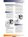
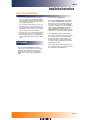
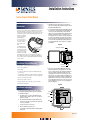
AMR-960
Installation Instructions
Sensus Tamper Detect Module
2. Install MIU at selected location and wire to encoder and
phone line according to MIU installation instructions. (Sensus
installation bulletin AMR-971R1)
Introduction
The Tamper Detect Module was designed for use with the Sensus
PhonRead system Meter Interface Unit (MIU) to indicate that possible tampering had occurred at the meter location. The “latch”
feature of the module immediately locks into a tamper detect position until reset at the location by authorized utility personnel. The
Tamper Detect Module
has four colored wires,
R=Red, B=Black,
G=Green, and Y=Yellow. These will be used
to install the Tamper
Detect Module to the
MIU.
R
3. It is recommended that the Tamper Detect Module be adhered
to the electronics cover plate inside the PhonRead MIU. This
can be done by removing the backing of the double stick
adhesive on the back of the Tamper Detect Module and pressing firmly onto the MIU electronics cover plate. Be sure to
mount module on the cover plate close enough so that the red
(R), green (G), and black (B) wires coming from the module
can be connected to the proper MIU port. The proper port is
the one that will be programmed by the MIU Programmer for
use with “Tamper Module.” This is usually Port 2 of the MIU.
See diagram A.
diagram A
Yellow
The following Tamper
Detect Module installaBlack
tion instructions provide
Green
for the minimum requireRed
ments for a successful
installation. This installation instruction document is only for installation of the Tamper
Detect Module. For instructions on installing other AMR devices,
please request and refer to the individual installation instructions
for those devices.
Tamper Detect Module
Installation Tools and Materials
Electronics
Cover Plate
● Screwdriver – Small standard head for terminal screws
● Wire cutter and stripper
● Wire stapler
● 2-conductor solid wire for Tamper Latch Module wiring only
(Sensus spec)
● 5-conductor wire minimum for combined Tamper Latch Module
wiring and absolute encoder wiring – Sensus spec (Optional)
● Plastic coated (jacketed) seal wire
● 3M UY-2 gel-cap wire connectors
● MIU Programmer, module and cable (Sensus 4000 HHD)
4. Next, connect the wires (RED, GREEN, BLACK) from the
Tamper Detect Module) to the appropriate port of the MIU.
Prior to connecting the wires to the terminals of the MIU, the
wire jacket should be stripped approximately 1/4" at end,
exposing bare wire for each of the colored wires. Be sure to
match the wire colors from the Tamper Detect Module to the
proper terminals of the MIU port – RED to “R”, GREEN to “G”,
and BLACK to “B”. Insert bare wire end into appropriate wire
location and tighten terminal screw to secure wire connection
to the terminal block. Check each connection by pulling wire
gently. See diagram B.
● MIU Programming software
diagram B
Installation Instructions
1. Based upon the MIU installation instructions, the following
recommended installation guidelines should be considered for
an actual MIU installation:
a. Placement which is accessible to both utility meter and
intended customer’s telephone line access – and the telephone line is working
b. Recommend inside installation (outside permitted) away
from excessive amounts of heat and moisture. (Pit installations not recommended.)
Yellow
Red
Green
Black
c. Consider convenience of homeowner
d. Room for installation and future access
e. Consideration for optional TouchRead TouchPad installation
if being used
Page 1 of 4
AMR-960
Installation Instructions
Sensus Tamper Detect Module
5. All that remains to be connected is the YELLOW “Y” wire. This
wire is used to create a continuity loop to where the tamper
detect is desired to be installed. This is usually a meter location.
If the MIU is located near the meter installation, a single plastic
coated seal wire can be used to create the continuity loop with
the Tamper Detect Module.
b. Connect one end of the two-conductor wire or one of the pair
of wires of the multi-conductor wire to the yellow “Y” wire on
the Tamper Detect Module. It is recommended that you use a
3M UY-2 gel-cap connector to connect the wires. The ends of
the wires need not be stripped to use with the gel-cap connector.
If the MIU is a further distance away from the meter, a separate
wire connection is recommended. This separate wire connection can be part of a multi-conductor wire that is used to connect the meter encoder to the MIU or a separate two-conductor
wire that can be installed to the meter location. In either event,
the Tamper Detect Module installation is the same.
c. At the other end of the long run of wire connect the plastic
coated seal wire to the same color of the two-conductor or
multi-conductor wire that is connected to the Yellow “Y" wire of
the Tamper Detect module. It is recommended that you use a
3M UY-2 gel-cap connector to connect the wires. The ends of
the wires need not be stripped to use with the gel-cap connector.
d. Run the plastic coated seal wire through the desired tamper
location (i.e., – meter connection nut, register seal hole, meter
cap screw, etc.) and back to the long run of wire.
Connecting the Continuity Loop
For a single wire connection:
a. Connect one end of the single plastic coated seal wire to the
yellow “Y” wire on the Tamper Detect Module. It is recommended that you use a 3M UY-2 gel-cap connector to connect
the wires. The end of the plastic coated seal wire need not
be stripped to use with the gel-cap connector.
b. Run the plastic coated seal wire through the desired tamper
location (i.e., meter connection nut, register seal hole, meter
cap screw, etc.) and back to the MIU.
Note: Be sure not to make a cut in the plastic coat of the seal wire
or you will receive a false tamper indication on the PhonRead
software. See diagram below.
NOTE: Be sure not to make a cut in the plastic coat of the seal wire
or you will receive a false tamper indication on the PhonRead software. See diagram below.
Yellow Wire
Gel-cap
Two-Conductor
or
Multi-Conductor
“Long Run” Wire
Programmer Port
TP “10” Connector
Port 2
Yellow Wire
Gel-cap
Gel-caps
Coated
Seal Wire
Coated
Seal Wire
Phone Line
Connection
‘TP’ Connect
Port 2
c. Strip off approximately 1/4" of the coating on the seal wire or
connection to the MIU terminal strip. If Port 1 of the MIU has
been programmed for “Tamper Module” connect the seal wire
end to the TP terminal marked 5 on the MIU circuit board; if
Port 2 was programmed for “Tamper Module,” connect the
seal wire end to the TP terminal connection marked 10 on the
MIU circuit board.
d. This completes the tamper loop connection. Proceed to the
Testing section.
For a separate wire (long run) connection:
a. For a long run connection you need a separate length of twoconductor wire or an extra “pair” of wires in a multi-conductor
length of wire. This long run of wire must run from the MIU to
the tamper detect location.
Testing
After installing the Tamper Detect Module, the operation of the device
can be tested as follows:
a. Use an Sensus Solid State Interrogator (SSI) that has been
loaded with the MIU programming software module.
b. Connect the SSI to the MIU programming port using the MIU
programming cable. For detailed instructions on using the SSI
to program an MIU, refer to the SSI Programming User’s Manual, literature #AMR-986.
c. You will be using the MIU Commands feature of the SSI to
check the port to which the Tamper Connect Module is
installed. These instructions are located on pages 3-11 to 3-14
of the SSI Programming User’s Manual.
d. At the first view screen of the SSI in MIU programming mode,
press the “Shift” key, then the “Sensus Logo” key. This will
bring up programming options “1-Edit Defaults” and “2-MIU
Commands”. Select “2-MIU Commands”.
Page 2 of 4
AMR-960
Installation Instructions
Sensus Tamper Detect Module
e. A list of commands will display on the SSI screen. Using the
arrow keys, scroll down to the “Clear Tamper” key command.
Enter the port number to which the Tamper Detect Module is
connected and press the “Enter” key. The response on the SSI
screen should be “Tamper Cleared”.
f.
A list of commands will again display on the SSI screen.
Using the arrow keys, scroll up to the “Read Data from
Port" command. Enter the port number to which the Tamper
Detect Module is connected and press the “Enter” key. The
response on the SSI screen should be “Tamper OK”.
g. If the proper response is received, verify the tamper data from
the port again. If the response is correct, complete the installation for the MIU as described in the SSI programming manual and on the MIU Installation Instructions, literature #AMR971R1).
Troubleshooting
1. If no response from MIU port:
After checking the “Read Data from Port” command you
receive no response. Check the wiring connection of the Tamper
Detect Module. After verifying that all connections are correct,
attempt to read the port again. If successful, complete MIU
installation. If unsuccessful, try using another Tamper Detect
Module.
2. If response from MIU is “Tamper Detected”:
After checking the “Read Data from Port” command and the
SSI screen displays “Tamper Detected”, the Tamper Detect
Module will need to be reset. Using the MIU Commands of the
SSI, scroll down the list of commands to the “Clear Tamper”
command. Press the “Enter” key on the SSI to clear the tamper
indication. Repeat the “Read Data from Port” command. If
response is “Tamper OK”, complete MIU installation. If
“Tamper Detected” is again displayed, attempt to clear tamper
again. If unsuccessful, try using another Tamper Detect Module.
3. To clear “Tamper Detect” indication after MIU installation:
Once installed, the MIU will call into the PhonRead system software on schedule. If tamper has been detected at a Tamper
Detect Module installation, there will be an indication on the
PhonRead system software. To clear the tamper indication, a
site visit must be made to the MIU installation. An SSI in MIU
programming mode is required.
To clear the tamper indication, follow the instructions above in
Step 2 of this Troubleshooting section. The tamper mode should
also be verified that it is in the “enabled” mode.
Page 3 of 4
AMR-960
Installation Instructions
Sensus Tamper Detect Module
Page 4 of 4