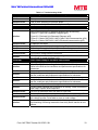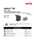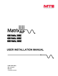
1
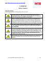
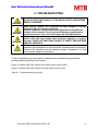
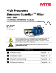
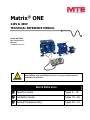
® Matrix ONE 240V & 480V TECHNICAL REFERENCE MANUAL FORM: MS-TRM-E REL. October 2015 REV. 001 © 2015 MTE Corporation High Voltage! Only a qualified electrician can carry out the electrical installation of this filter. WARNING Quick Reference ❶ Selection Guide Pages 6 – 18 ❷ Installation Guide Pages 19 – 28 ❸ Startup/Troubleshooting Pages 29 – 33 Matrix® ONE Technical Reference Manual 240V & 480V TABLE OF CONTENTS 1. WARNINGS .................................................................................................................................................... 3 WARNINGS AND CAUTIONS ................................................................................................................ 3 PRODUCT SAFETY LABELING ............................................................................................................. 3 GENERAL SAFETY INSTRUCTIONS ...................................................................................................... 4 2. INTRODUCTION ............................................................................................................................................. 5 RECEIPT & REPAIR STATEMENT ........................................................................................................ 5 3. HOW TO SELECT .......................................................................................................................................... 6 SELECTION GUIDE ............................................................................................................................ 6 PART NUMBER CONFIGURATION ........................................................................................................ 7 MATRIX ONE 240 VOLTS, 60HZ ........................................................................................................ 8 Part Number Selection Tables ................................................................................................................... 8 FILTER EFFICIENCY + WATT LOSS ................................................................................................... 10 Matrix ONE 240V, 60Hz ........................................................................................................................... 10 MATRIX ONE 480 VOLTS, 60HZ ...................................................................................................... 11 Part Number Selection Tables ................................................................................................................. 11 FILTER EFFICIENCY + WATT LOSS ................................................................................................... 13 Matrix ONE 480V, 60Hz ........................................................................................................................... 13 4. PRODUCT SPECIFICATIONS ..................................................................................................................... 14 PERFORMANCE SPECIFICATIONS ..................................................................................................... 14 ENCLOSURES ................................................................................................................................. 15 AGENCY APPROVALS ...................................................................................................................... 15 WARRANTY..................................................................................................................................... 15 OVER TEMPERATURE SWITCH ......................................................................................................... 15 5. TYPICAL PERFORMANCE DATA .............................................................................................................. 16 LOAD EFFECT ON THID .................................................................................................................. 16 TYPICAL HARMONIC SPECTRUM ...................................................................................................... 16 POWER FACTOR .............................................................................................................................17 ALTITUDE DERATING ....................................................................................................................... 17 ALTITUDE DERATING ....................................................................................................................... 18 6. HOW TO INSTALL ....................................................................................................................................... 19 INSTALLATION CHECKLIST ............................................................................................................... 19 GROUNDING .................................................................................................................................. 20 POWER WIRING CONNECTION ......................................................................................................... 21 BASIC SCHEMATIC DIAGRAMS ......................................................................................................... 23 OPEN PANEL UNIT INTERCONNECTION DIAGRAM ............................................................................. 24 ENCLOSED UNIT INTERCONNECTION DIAGRAM................................................................................. 25 CONTACTOR WIRING OPTION .......................................................................................................... 26 TORQUE RATINGS ........................................................................................................................... 27 TORQUE RATINGS ........................................................................................................................... 28 7. START UP .................................................................................................................................................... 29 STARTUP CHECKLIST ...................................................................................................................... 29 8. TROUBLESHOOTING.................................................................................................................................. 31 HARMONIC FILTER FIELD CHECKS ................................................................................................... 32 Form: MS-TRM-E October 2015 REV. 001 1 Matrix® ONE Technical Reference Manual 240V & 480V List of Figures Figure 5-1: Load Effect on THID ................................................................................................................. 16 Figure 5-2: Typical Harmonic Spectrum with and without Matrix ONE ....................................................... 16 Figure 5-3: Matrix ONE %Load vs Power Factor ........................................................................................ 17 Figure 5-4: Altitude Derating Curve ............................................................................................................ 17 Figure 5-5: Temperature Derating .............................................................................................................. 18 Figure 6-1: Open Unit Schematic Diagram ................................................................................................. 23 Figure 6-2: Enclosed Unit Schematic Diagram ........................................................................................... 23 Figure 6-3: Matrix ONE 240V & 480V Open Panel Interconnection ........................................................... 24 Figure 6-4: Matrix ONE 240V & 480V Enclosed Interconnection ............................................................... 25 List of Tables Table 3-1: Matrix ONE 240V Open Panel ..................................................................................................... 8 Table 3-2: Matrix ONE 240V Enclosed ......................................................................................................... 9 Table 3-3: Watt Loss - Matrix ONE 240V, 60Hz ......................................................................................... 10 Table 3-4: Matrix ONE 480V Open Panel ................................................................................................... 11 Table 3-5: Matrix ONE 480V Enclosed ....................................................................................................... 12 Table 3-6: Watt Loss - Matrix ONE 480V, 60Hz ......................................................................................... 13 Table 4-1: Performance Specifications ....................................................................................................... 14 Table 4-2: Over Temperature Switch .......................................................................................................... 15 Table 6-1: Torque Ratings-240V ................................................................................................................. 27 Table 6-2: Torque Ratings-480V ................................................................................................................. 28 Table 8-1: Troubleshooting Guide .............................................................................................................. 33 Form: MS-TRM-E October 2015 REV. 001 2 Matrix® ONE Technical Reference Manual 240V & 480V 1. WARNINGS Warnings and Cautions There are two types of warnings in this manual: WARNING describes situations that can lead to serious faults, physical injuries, or even death. WARNING Caution describes situations that can lead to malfunction or possible equipment damage. Caution The following symbols are used in this manual: High Voltage Warning: warns of situations that dangerously high voltage is involved. Failure to use proper precautions may lead to serious injury or even death. WARNING General Warning: warns of situations that can result in serious injury or death if proper precautions are not used. WARNING General Caution: identifies situations that could lead to malfunction or possible equipment damage. Caution Product Safety Labeling The following labels are placed on the Matrix ONE product: Label notes to installer to refer to instruction manual first before installing. Wait five minutes for capacitors to discharge. Verify safe voltage level before servicing. High Voltage: surfaces on product can have high voltage which can cause injury. Connect Thermal Switch: connecting the thermal switch can reduce risk of damage. Hot Surfaces: surfaces of product can be hot at times and cause burns. Form: MS-TRM-E October 2015 REV. 001 3 Matrix® ONE Technical Reference Manual 240V & 480V General Safety Instructions High Voltage! Only a qualified electrician can carry out the electrical installation of this filter. WARNING High voltage is used in the operation of this filter. Use extreme caution to avoid contact with high voltage when operating, installing or repairing this filter. Injury or death may result if safety precautions are not observed. The opening of the branch circuit protective device may be an indication that a fault current has been interrupted. To reduce the risk of fire or electrical shock, currentcarrying parts and other components of the filter should be examined and replaced if damaged. An upstream disconnect/protection device must be used as required by the National Electrical Code (NEC) or governing authority. Even if the upstream disconnect/protection device is open, the drive down stream of the filter may feedback high voltage to the filter. The drive safety instructions must be followed. Injury or death may result if safety precautions are not observed. WARNING The filter must be grounded with a grounding conductor connected to all grounding terminals. Open panel filters must have reactor grounded through a 2”x2” area cleaned of paint and varnish on lower mounting bracket. Only spare parts obtained from MTE Corporation or an authorized MTE distributor can be used. After removing power, allow at least five minutes to elapse and verify that the capacitors have discharged to a safe level before contacting internal components. Connect a DC voltmeter across the capacitor terminals and ensure that the voltage is at a safe level. Loose or improperly secured connections may damage or degrade filter performance. Visually inspect and secure all electrical connections before power is applied to the filter. Caution The user of this filter must assure that the input voltage and frequency is correct for the filter rating and that the voltage applied falls within the rated operating tolerance envelop specified for the filter. For severe power line applications where the power feed is likely to experience surges and transients that exceed the input voltage rating, it is recommended that a TVSS (Transient Voltage Surge Suppression) or SPD (Surge Protection Device) be deployed ahead of the filter to reduce the possibility of exceeding the filter rated voltage. Consult with TVSS or SPD manufacturer to determine the correct protection requirements for your power line conditions. Form: MS-TRM-E October 2015 REV. 001 4 Matrix® ONE Technical Reference Manual 240V & 480V 2. INTRODUCTION The purpose of the manual is to properly specify, size, and install the Matrix ONE. For most current information, please refer to website www.mtecorp.com/matrix‐one‐single‐phase‐filters Receipt & Repair Statement Upon Receipt of this Filter: The Matrix ONE Harmonic Filter has been subjected to demanding factory tests before shipment. Carefully inspect the shipping container for damage that may have occurred in transit. Then unpack the filter and carefully inspect for any signs of damage. Save the shipping container for future transport of the filter. In the event of damage, please contact and file a claim with the freight carrier involved immediately. If the equipment is not going to be put into service upon receipt, cover and store the filter in a clean, dry location. After storage, ensure that the equipment is dry and that no condensation or dirt has accumulated on the internal components of the filter before applying power. Repair/Exchange Procedure MTE Corporation requires a Return Material Authorization Number and form before we can accept any filters that qualify for return or repair. If problems or questions arise during installation, setup, or operation of the filter, please contact MTE for assistance at: Toll Free: 1-800-455-4MTE (1-800-455-4683) International Tel: +1-262-253-8200 Fax: +1-262-253-8222 Form: MS-TRM-E October 2015 REV. 001 5 Matrix® ONE Technical Reference Manual 240V & 480V 3. HOW TO SELECT Caution Prior to filter selection, please consult drive manual/manufacturer to ensure drive is suitable for single phase filter application, system ratings are understood in single phase operation, and to configure proper parameters. Failure to do so may result in failure of drive, filter, or other equipment. Selection Guide The MTE Corporation Matrix ONE Harmonic Filter is designed for harmonic mitigation of 4-pulse inverter drives supplying variable torque loads in a wide variety of applications. The suitability of this filter for a specific application must therefore be determined by the customer. In no event will MTE Corporation assume responsibility or liability for any direct or consequential damages resulting from the use or application of this filter, nor will MTE Corporation assume patent liability with respect to the use of information, circuits or equipment described in this instruction manual. Matrix ONE Harmonic Filters are available in Open Panel, NEMA 1/2, and 3R mechanical configurations. For inverters feeding isolation transformers select a filter with a current rating equal to or greater than that of the transformer primary current. Please verify information below for proper selection: Line Voltage and Frequency: Input voltage 240V or 480V, 60 Hz. See Table 4-1 (p14) for specification. Current Rating: 240V 17-620 Amp; 480V 8-310 Amp. Voltage Distortion: For environments where voltage distortion exceeds 2%, contact MTE at 1-800-455-4MTE (1-800-455-4683) for derating information. Contactor Option: Matrix ONE is equipped with user installable contactor options. See “Contactor Wiring Option” (p26). Performance: See Table 4-1: Performance Specifications (p14) for specification. Altitude: 3,300 feet above sea level without derating. See Figure 5-4: Altitude Derating Curve (p17) for derating information. Enclosure Type: Open Panel, NEMA 1/2 & NEMA 3R, see Enclosures (p15) for enclosure descriptions. Temperature: See Table 4-1: Performance Specifications (p14) for operating temperature information and Figure 5-5: Temperature Derating (p18) for derating information. Form: MS-TRM-E October 2015 REV. 001 6 Matrix® ONE Technical Reference Manual 240V & 480V Part Number Configuration MS x ____ x Matrix ONE Enclosure Type P = Panel Mount (No Enclosure) G = General Purpose (NEMA 1/2) W = Weather (NEMA 3R) Current Rating 0008 is 8 Amps 0090 is 90 Amps 0620 is 620 Amps Voltage Frequency Code A 240 Volts 60 Hz D 480 Volts 60 Hz Additional Options Standard NEMA 3R enclosure with optional rodent/serpent screen Form: MS-TRM-E October 2015 REV. 001 7 Matrix® ONE Technical Reference Manual 240V & 480V Matrix ONE 240 Volts, 60Hz Part Number Selection Tables Open Panel Table 3-1: Matrix ONE 240V Open Panel Filter Amps Rating Part Number 17 MSP0017A 26 App. Wt. Capacitor Panel Size (in.) (H x W x D) Capacitor Panel P/N 47 8.7 x 10.5 x 7.2 CAPPANEL-015 6.9 x 14.0 x 6.0 MSP0026A 52 8.7 x 10.5 x 7.7 CAPPANEL-016 6.9 x 14.0 x 6.0 38 MSP0038A 69 10.5 x 12.0 x 9.6 CAPPANEL-017 6.9 x 18.4 x 7.0 49 MSP0049A 79 10.5 x 12.0 x 10.2 CAPPANEL-019 6.9 x 18.4 x 7.0 73 MSP0073A 114 10.6 x 12.0 x 12.0 CAPPANEL-020 10.7 x 18.4 x 7.0 94 MSP0094A 150 15.2 x 15.3 x 10.9 CAPPANEL-021 10.7 x 16.3 x 7.6 115 MSP0115A 167 15.2 x 15.3 x 11.6 CAPPANEL-023 6.9 x 16.3 x 7.6 140 MSP0140A 202 15.2 x 15.3 x 12.3 CAPPANEL-018 10.7 x 16.3 x 7.6 180 MSP0180A 249 15.3 x 15.3 x 14.6 CAPPANEL-086 10.7 x 16.3 x 7.6 225 MSP0225A 296 18.3 x 15.3 x 13.8 CAPPANEL-092 10.7 x 16.3 x 7.6 265 MSP0265A 318 18.4 x 15.3 x 14.9 CAPPANEL-093 CAPPANEL-093 10.7 x 16.3 x 7.6 10.7 x 16.3 x 7.6 330 MSP0330A 376 18.4 x 15.3 x 16.7 CAPPANEL-093 CAPPANEL-094 10.7 x 16.3 x 7.6 10.7 x 16.3 x 7.6 430 MSP0430A 611 20.5 x 24.0 x 17.4 CAPPANEL-097 CAPPANEL-098 10.7 x 16.3 x 7.6 8.9 x 16.3 x 7.6 540 MSP0540A 718 20.6 x 24.0 x 18.5 CAPPANEL-099 CAPPANEL-101 10.7 x 16.3 x 7.6 11.5 x 16.3 x 7.6 620 MSP0620A 826 20.6 x 24.0 x 19.7 CAPPANEL-101 CAPPANEL-101 11.5 x 16.3 x 7.6 11.5 x 16.3 x 7.6 (lbs.)* Open Magnetics (in.) (H x W x D) Note: Approximate weight of filter above includes weight of reactor and accompanying cap-panel assembly. Form: MS-TRM-E October 2015 REV. 001 8 Matrix® ONE Technical Reference Manual 240V & 480V Matrix ONE 240 Volts, 60Hz Part Number Selection Tables Enclosed Table 3-2: Matrix ONE 240V Enclosed Filter Amps Rating NEMA 1/2 Enclosure App. Wt (lbs.) NEMA 3R Enclosure App. Wt (lbs.) 17 MSG0017A CAB-12AP2 95 MSW0017A CAB-12AP3 102 26 MSG0026A CAB-12AP2 100 MSW0026A CAB-12AP3 108 38 MSG0038A CAB-17AP2 144 MSW0038A CAB-17AP3 155 49 MSG0049A CAB-17AP2 155 MSW0049A CAB-17AP3 166 73 MSG0073A CAB-17AP2 190 MSW0073A CAB-17AP3 201 94 MSG0094A CAB-26AP2 320 MSW0094A CAB-26AP3 333 115 MSG0115A CAB-26AP2 337 MSW0115A CAB-26AP3 350 140 MSG0140A CAB-26AP2 372 MSW0140A CAB-26AP3 385 180 MSG0180A CAB-26AP2 420 MSW0180A CAB-26AP3 433 225 MSG0225A CAB-26AP2 466 MSW0225A CAB-26AP3 479 265 MSG0265A CAB-42AP2 742 MSW0265A CAB-42AP3 779 330 MSG0330A CAB-42AP2 801 MSW0330A CAB-42AP3 838 430 MSG0430A CAB-42AP2 1042 MSW0430A CAB-42AP3 1079 540 MSG0540A CAB-42AP2 1148 MSW0540A CAB-42AP3 1184 620 MSG0620A CAB-48AP2 1454 MSW0620A CAB-48AP3 1495 Form: MS-TRM-E October 2015 REV. 001 9 Matrix® ONE Technical Reference Manual 240V & 480V Filter Efficiency + Watt loss Matrix ONE 240V, 60Hz Maximum Output (Amps RMS) Table 3-3: Watt Loss - Matrix ONE 240V, 60Hz 240V Capacitor Current Efficiency Power Dissipation @ 240V Typical Rated Current Typical (%) Typical (Amps RMS) (Watts) 17 97.5% 181 9.5 26 97.9% 228 14.5 38 98.4% 258 21.1 49 97.9% 430 27.2 73 98.5% 473 40.6 94 98.5% 636 52.3 115 98.7% 631 63.9 140 98.6% 805 77.8 180 98.6% 1055 101.2 225 99.0% 967 125.1 265 99.0% 1115 147.3 330 99.0% 1359 183.5 430 99.1% 1647 239.1 540 99.2% 1872 300.2 620 99.2% 2094 344.7 Note: Use the IEC AC-3 rating for the corresponding filter capacitor current when selecting a contactor. Form: MS-TRM-E October 2015 REV. 001 10 Matrix® ONE Technical Reference Manual 240V & 480V Matrix ONE 480 Volts, 60Hz Part Number Selection Tables Open Panel Table 3-4: Matrix ONE 480V Open Panel Filter Amps Rating Part Number App. Wt. (lbs.)* Open Magnetics (in.) (H x W x D) Capacitor / Capacitor Panel P/N Capacitor Size (in.) (H x D) Capacitor Panel Size (in.) (H x W x D) 8 MSP0008D 41 8.6 x 10.5 x 7.2 CAP-364TP 5.5 x 3.9 13 MSP0013D 51 8.7 x 10.5 x 7.7 CAP-366TP 5.5 x 4.6 19 MSP0019D 67 10.5 x 12.0 x 8.0 CAP-367TP 5.5 x 4.6 24 MSP0024D 75 10.5 x 12.0 x 8.5 CAP-368TP 7.2 x 4.6 37 MSP0037D 112 10.6 x 12.0 x 11.8 CAPPANEL-014 6.8 x 18.4 x 7.0 47 MSP0047D 146 15.2 x 15.3 x 10.9 CAPPANEL-013 10.8 x 16.6 x 7.6 59 MSP0059D 159 15.2 x 15.3 x 11.4 CAPPANEL-004 7.9 x 16.3 x 7.6 69 MSP0069D 166 15.1 x 15.3 x 11.9 CAPPANEL-012 6.9 x 16.3 x 7.6 90 MSP0090D 217 15.2 x 15.3 x 13.2 CAPPANEL-024 6.9 x 16.3 x 7.6 110 MSP0110D 256 18.3 x 15.3 x 13.0 CAPPANEL-026 7.9 x 16.3 x 7.6 135 MSP0135D 299 18.3 x 15.3 x 14.3 CAPPANEL-028 8.9 x 16.3 x 7.6 165 MSP0165D 349 18.3 x 15.3 x 15.4 CAPPANEL-029 10.7 x 16.3 x 7.6 215 MSP0215D 586 20.4 x 24.0 x 15.8 CAPPANEL-030 CAPPANEL-030 6.9 x 16.3 x 7.6 6.9 x 16.3 x 7.6 270 MSP0270D 689 20.3 x 24.0 x 18.7 CAPPANEL-024 CAPPANEL-095 6.9 x 16.3 x 7.6 7.9 x 16.3 x 7.6 310 MSP0310D 785 20.3 x 24.0 x 20.2 CAPPANEL-096 CAPPANEL-096 6.9 x 16.3 x 7.6 6.9 x 16.3 x 7.6 Note: Approximate weight of filter above includes weight of reactor and accompanying capacitor and/or cap-panel assembly. Form: MS-TRM-E October 2015 REV. 001 11 Matrix® ONE Technical Reference Manual 240V & 480V Matrix ONE 480 Volts, 60Hz Part Number Selection Tables Enclosed Table 3-5: Matrix ONE 480V Enclosed Filter Amps Rating NEMA 1/2 Enclosure App. Wt (lbs.) NEMA 3R Enclosure App. Wt (lbs.) 8 MSG0008D CAB-12AP2 89 MSW0008D CAB-12AP3 97 13 MSG0013D CAB-12AP2 98 MSW0013D CAB-12AP3 106 19 MSG0019D CAB-17AP2 142 MSW0019D CAB-17AP3 153 24 MSG0024D CAB-17AP2 150 MSW0024D CAB-17AP3 160 37 MSG0037D CAB-17AP2 188 MSW0037D CAB-17AP3 198 47 MSG0047D CAB-26AP2 311 MSW0047D CAB-26AP3 324 59 MSG0059D CAB-26AP2 325 MSW0059D CAB-26AP3 338 69 MSG0069D CAB-26AP2 333 MSW0069D CAB-26AP3 346 90 MSG0090D CAB-26AP2 387 MSW0090D CAB-26AP3 400 110 MSG0110D CAB-26APD2 499 MSW0110D CAB-26APD3 525 135 MSG0135D CAB-26APD2 542 MSW0135D CAB-26APD3 568 165 MSG0165D CAB-26APD2 592 MSW0165D CAB-26APD3 617 215 MSG0215D CAB-42AP2 1009 MSW0215D CAB-42AP3 1045 270 MSG0270D CAB-42AP2 1111 MSW0270D CAB-42AP3 1148 310 MSG0310D CAB-48AP2 1405 MSW0310D CAB-48AP3 1445 Form: MS-TRM-E October 2015 REV. 001 12 Matrix® ONE Technical Reference Manual 240V & 480V Filter Efficiency + Watt loss Matrix ONE 480V, 60Hz Maximum Output (Amps RMS) Table 3-6: Watt Loss - Matrix ONE 480V, 60Hz 480V Capacitor Current Efficiency Power Dissipation @ 480V Typical Rated Current Typical (%) Typical (Amps RMS) (Watts) 8 97.50% 184 4.4 13 97.87% 219 7.2 19 98.05% 292 10.6 24 98.15% 350 13.3 37 98.56% 509 20.6 47 98.52% 667 26.1 59 98.61% 648 32.8 69 98.84% 629 38.4 90 98.85% 818 50.0 110 98.84% 1010 61.2 135 98.79% 1287 75.1 165 98.85% 1503 91.7 215 99.17% 1409 119.5 270 99.23% 1641 150.1 310 99.27% 1797 172.4 Note: Use the IEC AC-3 rating for the corresponding filter capacitor current when selecting a contactor. Form: MS-TRM-E October 2015 REV. 001 13 Matrix® ONE Technical Reference Manual 240V & 480V 4. PRODUCT SPECIFICATIONS Performance Specifications Table 4-1: Performance Specifications Service Conditions Input Voltage(s) Maximum THID Input voltage line distortion Minimum source impedance Service Factor Overload Ambient Temperature (Operating) Open Panel Filters Enclosed Filters Storage Temperature Altitude Relative Humidity Over Voltage Insertion Load Load: Typically a 4-pulse rectifier 240 VAC ± 10%, 60 ± 0.75 Hz 1 phase 480 VAC ± 10%, 60 ± 0.75 Hz 1 phase 12% at full load 1% maximum to ensure performance guaranty 1.5% 1.00 150% for 1 minute duration -40 to +50 degrees C -40 to +40 degrees C -40 to +90 degrees C 0 to 3300 Feet above sea level. Refer to Figure 5-4: Altitude Derating Curve 0 to 95% non-condensing Category II +10% no load -10% full load Notes (SCCR): The Short Circuit Current Rating (SCCR) is not required under Exception No.1 of UL508A SB4.2.1 effective 4/25/06. This exception also applies to all the Contactor Options (002, 009, 012, and similar), where the Contactors are separated from the Main Power path by exempt components (such as Reactors) of sufficient Impedance, which is assured in case of the Reactors that are integral components of our Filter. Form: MS-TRM-E October 2015 REV. 001 14 Matrix® ONE Technical Reference Manual 240V & 480V Enclosures MTE enclosures are designed to provide a degree of protection for electrical components and prevent incidental personnel contact with the enclosed equipment. Depending on the enclosure selected, these enclosures meet the requirements of NEMA 1/2 or 3R. An approximate cross reference guide between NEMA, UL, CSA and IEC enclosure follows. Type 1 NEMA / IEC IP20 Enclosure: Are designed for indoor use and will provide protection against contact with the enclosed equipment. Type 2 NEMA / IEC IP20 Enclosure: Are designed for indoor use and will provide protection against contact with the enclosed equipment and provide a degree of protection against limited amounts of falling water and dirt. Type 3R NEMA / IEC IP23 Enclosure: Are designed for outdoor use primarily to provide protection against contact with the enclosed equipment and provide a degree of protection against falling rain sleet and external ice formation. Agency Approvals UL and cUL listed to UL508 Type MX and CSA-C22.2 No 14-95 File E180243 (1-999 Ampere, 120VAC through 690VAC 50/60Hz 1 or 3 phase). Warranty Three years from the date of shipment. See www.mtecorp.com for details. Over Temperature Switch Table 4-2: Over Temperature Switch NC Switch opens at 180 Deg. +/- 5 Deg. C Current Amps Voltage Contact Load 6 120 AC Resistive Loads 3 120 AC Inductive Loads 3 240 AC Resistive Loads 2.5 240 AC Inductive Loads 8 12 VDC Resistive Loads 4 24 VDC Resistive Loads MTE highly recommends the use of the over temperature switch to prevent damage to the filter in rare instances of overheating from abnormal operating conditions. Form: MS-TRM-E October 2015 REV. 001 15 Matrix® ONE Technical Reference Manual 240V & 480V 5. TYPICAL PERFORMANCE DATA Load Effect on THID Percent THID (%) Matrix® ONE THID Reduction (%) 18 16 14 12 10 8 6 4 2 0 0.0 20.0 40.0 60.0 80.0 100.0 Percentage of Full Load (%) Figure 5-1: Load Effect on THID Typical Harmonic Spectrum 70.0% HARMONIC CURRENT [%] 60.0% 50.0% 40.0% 30.0% 20.0% 10.0% 0.0% 3 5 7 9 11 13 15 17 HARMONIC NUMBER [n] DRIVE 100% LOAD 19 21 MATRIX ONE 100% LOAD 23 Figure 5-2: Typical Harmonic Spectrum with and without Matrix ONE Form: MS-TRM-E October 2015 REV. 001 16 Matrix® ONE Technical Reference Manual 240V & 480V Power Factor PF Input 1.20 Leading pF 1.00 0.80 0.60 0.40 0.20 0.00 0.0 20.0 40.0 60.0 80.0 100.0 120.0 Matrix ONE %Load Figure 5-3: Matrix ONE %Load vs Power Factor Altitude Derating Figure 5-4: Altitude Derating Curve Form: MS-TRM-E October 2015 REV. 001 17 Matrix® ONE Technical Reference Manual 240V & 480V Altitude Derating Figure 5-5: Temperature Derating Form: MS-TRM-E October 2015 REV. 001 18 Matrix® ONE Technical Reference Manual 240V & 480V 6. HOW TO INSTALL Installation Checklist WARNING WARNING WARNING WARNING Prior to installation, please refer to all general warnings on page 3. Failure to practice this can result in bodily injury! Input and output wiring to the filter should be performed by authorized personnel in accordance with NEC and all local electrical codes and regulations. The filter is designed for use with copper conductors with a minimum temperature rating of 75 degrees C. Do not install capacitor assembly above/near the Harmonic Mitigating Reactor. Premature or catastrophic failure may occur. Matrix Filters are supplied in the following mechanical configurations: Open Panel Mount Floor mounted general purpose NEMA 1/2, & 3R cabinets Select a well-ventilated area suitable for the NEMA enclosure type number. Do not install in or near a corrosive environment. Avoid locations where the filter would be subjected to excessive vibrations. Panel mounted filters are designed for mounting within the customer’s enclosure. Panel mount units consist of a Harmonic Mitigating Reactor (HMR) and one or more capacitor panel modules referred to as cap-panels on drawings and diagrams. The capacitor panel must be located in the lowest temperature regions of the enclosure – generally toward the bottom and away from high temperature components. Include the power dissipation of the filter along with all the other components located in the enclosure to determine the internal temperature rise and cooling requirements of the enclosure. Refer to Article 430 Table 430.91 of the National Electrical code for the selection of the appropriate enclosure Type Number for your application. Form: MS-TRM-E October 2015 REV. 001 19 Matrix® ONE Technical Reference Manual 240V & 480V Grounding The filter must always be grounded with a grounding conductor connected to ground terminals. WARNING For open panel units, ensure a 2” x 2” area is cleaned of paint and varnish on lower mounting bracket for ground connection. On NEMA 3R enclosures, CAB-26AP and larger, no live parts shall be mounted below 8 inches from the bottom of the enclosure. WARNING WARNING For cable shield grounding follow the drive manufactures recommendations. Over Temperature Interlock An over temperature interlock circuit should be used in conjunction with thermal switch to turn off the drive to prevent filter damage due to abnormal operating conditions. The temperature switch is normally closed and will open when an internal reactor temperature of 180°C is reached. See Table 4-2 (p15) for contact rating information and the drive user manual for interconnection information. Location & Spacing Open panel filters are designed for mounting in the customer’s enclosure. Include the power dissipation of the filter along with all the other components located in the panel to determine the internal temperature rise and cooling requirements of the enclosure. A general guideline is to allow a side clearance of eight (8) inches and a vertical clearance of eight (8) inches for proper heat dissipation and access within the enclosure. Clearances may be less if proper ventilation exists. Filter components must operate within temperatures specified in this manual or filter operating life will be compromised. Also be aware of minimum electrical clearances as defined by the appropriate system safety standard(s). Open panel Matrix ONE Filters generate heat and should be positioned away from heat sensitive components. Ensure that proper panel orientation is maintained. Keep the capacitors away from reactor heat flow. Avoid locations where the filter would be subjected to excessive vibrations. Locate the filter as close to the inverter as possible. General purpose NEMA 1/2 and NEMA 3R enclosed filters are designed for floor mounting in an environment suitable for the enclosure type. Do not install in or near a corrosive environment. Avoid locations where the filter would be subjected to excessive vibrations. Allow a minimum side and back clearance of eight (8) inches and front clearance of thirty-six (36) inches for proper heat dissipation and access. Locate the filter as close to the inverter as possible. Form: MS-TRM-E October 2015 REV. 001 20 Matrix® ONE Technical Reference Manual 240V & 480V Power Wiring Connection WARNING Input and output power wiring to the filter should be performed by authorized personnel in accordance with the NEC and all local electrical codes and regulations. Cable lugs and mounting hardware are provided by the customer. Any extremely low or high resistance readings indicate a mis-wire and may result in damage to filter components if not corrected. On NEMA 3R enclosures, CAB-26AP and larger, no live parts shall be mounted below 8 inches from the bottom of the enclosure. WARNING WARNING Verify that the power source to which the filter is to be connected is in agreement with the nameplate data on the filter. A fused disconnect switch or circuit breaker should be installed between the filter and its source of power in accordance with the requirements of the NEC and all local electrical codes and regulations. Refer to the drive user manual for selection of the correct fuse rating and class. For panel mounted filter applications, interconnection between the filter, its power source, the cap-panels, and the drive is shown in Figure 6-3 (p24). Wire gauge range and terminal torque requirements as well as selecting conductors that interconnect the HMR and capacitor assemblies are shown in Table 6-1 (p27) for 240V, Table 6-2 (p28) for 480V. Filters that use multiple cap-panels share total cap current shown on Table 3-3 (p10) for 240V, Table 3-6 (p13) for 480V. Refer to the drive user manual for instructions on interconnecting the drive and motor and the correct start-up procedures for the drive. The filter is designed for use with copper conductors with a minimum temperature rating of 75 degrees C. For filters supplied in general purpose NEMA 1/2 & 3R cabinets, interconnection between the filter, its power source, and the drive is shown in Figure 6-4 (p25). Refer to the drawings in the Appendix for the location of input, output, ground, and over temperature switch terminals. Refer to the drive user manual for instructions on interconnecting the drive and motor and the correct start-up procedures for the drive. Wiring Checks Using Figure 6-1 (p23) and Figure 6-2 (p23), visually check the wired components to confirm, verify, and correct wiring. Then, with a multi meter, check phase to phase isolation using the 100 K ohm range. The multi meter will read the parallel equivalent of the bleeder resistors after the capacitors initially charge. All phase to phase resistance values should be the same. Form: MS-TRM-E October 2015 REV. 001 21 Matrix® ONE Technical Reference Manual 240V & 480V Check for the Following Faults: Capacitor shorted Capacitor bus not connected Capacitor bus to chassis short Paralleling wiring errors Grounding and Ground Fault Protection The filter must always be grounded with a grounding conductor connected to all ground terminals. Due to high leakage currents associated with variable frequency drives, ground fault protective devices do not necessarily operate correctly when placed ahead of a Matrix Filter feeding a drive. When using this type of device, its function should be tested in the actual installation. Form: MS-TRM-E October 2015 REV. 001 22 Matrix® ONE Technical Reference Manual 240V & 480V Basic Schematic Diagrams Figure 6-1: Open Unit Schematic Diagram Figure 6-2: Enclosed Unit Schematic Diagram Form: MS-TRM-E October 2015 REV. 001 23 Matrix® ONE Technical Reference Manual 240V & 480V Open Panel Unit Interconnection Diagram Figure 6-3: Matrix ONE 240V & 480V Open Panel Interconnection Form: MS-TRM-E October 2015 REV. 001 24 Matrix® ONE Technical Reference Manual 240V & 480V Enclosed Unit Interconnection Diagram Figure 6-4: Matrix ONE 240V & 480V Enclosed Interconnection Form: MS-TRM-E October 2015 REV. 001 25 Matrix® ONE Technical Reference Manual 240V & 480V Contactor Wiring Option The Matrix ONE comes with a user configurable contactor wiring block. This option allows the user to add disconnect options to meet their applications. Refer to Figure 6-4 (p25) for the wiring diagram. The units will be shipped with factory installed jumpers as shown in the figure. Jumpers must be removed for installation of contactor option. Form: MS-TRM-E October 2015 REV. 001 26 Matrix® ONE Technical Reference Manual 240V & 480V Torque Ratings Matrix ONE 240V Table 6-1: Torque Ratings-240V Matrix ONE HMR Terminals Filter Rating (Amps) Input /Output Power U1-V1 / U2-V2 U3-V3/JP1 Interconnect Cap-panel Cap-panel Terminals U3-V3 240V Cap-panel Part Number Minimum Interconnect Wire Gauge (AWG) Terminal Torque (in-lbs.) Recommended Min. Wire Size (AWG) Terminal Torque (in-lbs.) Terminal Torque (in-lbs.) 17 14 16 16 CAPPANEL-015 14 60 26 10 16 16 CAPPANEL-016 14 60 38 8 16 16 CAPPANEL-017 12 60 49 8 16 16 CAPPANEL-019 10 60 73 4 16 16 CAPPANEL-020 8 60 94 2 16 16 CAPPANEL-021 6 60 115 2 N/A N/A CAPPANEL-023 6 60 140 1/0 N/A N/A CAPPANEL-018 4 60 180 3/0 N/A N/A CAPPANEL-086 2 60 225 4/0 N/A N/A CAPPANEL-092 1 60 265 1/0 (2x) or 300 kcmil N/A N/A CAPPANEL-093 CAPPANEL-093 1/0 1/0 60 60 330 2/0 (2x) or 400 kcmil N/A N/A CAPPANEL-093 CAPPANEL-094 3 3 60 60 430 250 kcmil (2x) N/A N/A CAPPANEL-097 CAPPANEL-098 1 1 60 60 540 300 kcmil (2x) N/A N/A CAPPANEL-099 CAPPANEL-101 1/0 1/0 60 60 620 350 kcmil (2x) N/A N/A CAPPANEL-101 CAPPANEL-101 2/0 2/0 60 60 Note: Cap-panel interconnect wiring specification according to UL508 75° C Table. Note: To prevent flexing or bending of the coil windings attached to Matrix ONE HMR Flat copper terminal tabs, use two wrenches to tighten customer provided cable mounting hardware. Form: MS-TRM-E October 2015 REV. 001 27 Matrix® ONE Technical Reference Manual 240V & 480V Torque Ratings Matrix ONE 480V Table 6-2: Torque Ratings-480V Matrix ONE HMR Terminals Filter Rating (Amps) Input /Output Power U1-V1 / U2-V2 U3-V3/JP1 Interconnect Cap-panel Cap-panel Terminals U3-V3 480V Cap-panel Part Number Minimum Interconnect Wire Gauge (AWG) Terminal Torque (in-lbs.) Recommended Min. Wire Size (AWG) Terminal Torque (in-lbs.) Terminal Torque (in-lbs.) 8 14 16 16 CAP-364TP 14 23 13 14 16 16 CAP-366TP 14 23 19 14 16 16 CAP-367TP 14 23 24 12 16 16 CAP-368TP 14 23 37 8 16 16 CAPPANEL-014 12 60 47 6 16 16 CAPPANEL-013 10 60 59 4 N/A 16 CAPPANEL-004 10 60 69 4 N/A 16 CAPPANEL-024 8 60 90 3 N/A N/A CAPPANEL-024 8 60 110 1 N/A N/A CAPPANEL-026 6 60 135 4 (2x) or 1/0 N/A N/A CAPPANEL-028 4 60 165 3 (2x) or 2/0 N/A N/A CAPPANEL-029 3 60 215 2 (2x) or 250 kcmil N/A N/A CAPPANEL-030 CAPPANEL-030 1/0 1/0 60 60 270 1/0 (2x) or 300 kcmil N/A N/A CAPPANEL-024 CAPPANEL-095 4 4 60 60 310 2/0 (2x) or 350 kcmil N/A N/A CAPPANEL-096 CAPPANEL-096 2/0 2/0 60 60 Note: Cap-panel interconnect wiring specification according to UL508 75° C Table. Note: To prevent flexing or bending of the coil windings attached to Matrix ONE HMR Flat copper terminal tabs, use two wrenches to tighten customer provided cable mounting hardware. Form: MS-TRM-E October 2015 REV. 001 28 Matrix® ONE Technical Reference Manual 240V & 480V 7. START UP Startup Checklist Safety Precautions Before startup, observe the following warnings and instructions: WARNING WARNING WARNING WARNING WARNING Internal components of the filter are at line potential when the filter is connected to the drive. This voltage is extremely dangerous and may cause death or severe injury if you come in contact with it. Remove all power to the Matrix ONE filter in compliance to standardized 26 CFR 1920.147 lockout/tagout policies. After disconnecting the utility power, wait at least 5 minutes before doing any work on the filter connections. After removing power, allow at least five minutes to elapse and verify that the capacitors have discharged to a safe level before contacting internal components. Connect a DC voltmeter across the capacitor terminals and ensure that the voltage is at a safe level. Use extreme caution to avoid contact with line voltage when checking for power. INJURY OR DEATH MAY RESULT IF SAFETY PRECAUTIONS ARE NOT OBSERVED. After disconnecting the utility power, wait at least 5 minutes before doing any work on the filter connections. After removing power, allow at least five minutes to elapse and verify that the capacitors have discharged to a safe level before contacting internal components. Connect a DC voltmeter across the capacitor terminals. Start with the meter on the highest scale and progressively switch to a lower scale as the indicated voltage falls below the maximum value of the scale used. Injury or death may result if the drive safety precautions are not observed. Damage to equipment may occur if the drive startup procedures are not observed. Form: MS-TRM-E October 2015 REV. 001 29 Matrix® ONE Technical Reference Manual 240V & 480V Sequence of Operation 1. Read and follow safety precautions. 2. After installation, ensure that: All filter ground terminals are connected to ground. Power wiring to the utility, drive and motor is in accordance with the power wiring connection diagrams shown in installation instructions section. Use the guidelines of Table 6-1 (p27) for 240V and Table 6-2 (p28) for 480V, for power and cappanel wire gauges. 3. Check that moisture has not condensed on the filter components. If moisture is present, do not proceed with startup until the moisture has been removed. 4. Disconnect the filter output from the drive. 5. Connect the filter to the utility. 6. Confirm that line voltage is present at the input terminals (U1, V1) of the filter. 7. Confirm that line voltage is present at the output terminals (U2, V2) of the filter and that it is less than or equal to 1.1 times the input voltage. 8. Using a clamp on Amp meter, check input phase currents to verify they are within a 5% match to each other and approximately 50% of filter current rating. 9. Remove power and verify that NO VOLTAGE is present on the filter terminals. 10. Connect the filter output to the drive. 11. Refer to the drive user manual for the drive startup procedure. Observe all safety instructions in the drive user manual. Form: MS-TRM-E October 2015 REV. 001 30 Matrix® ONE Technical Reference Manual 240V & 480V 8. TROUBLESHOOTING WARNING WARNING WARNING Caution INJURY OR DEATH MAY RESULT IF THE DRIVE SAFETY PRECAUTIONS ARE NOT OBSERVED. When properly installed, this equipment has been designed to provide maximum safety for operating personnel. However, hazardous voltages and elevated temperatures exist within the confines of the enclosure. Servicing should therefore be performed by qualified personnel only and in accordance with OSHA Regulations. High voltage is used in the operation of this filter. Use Extreme caution to avoid contact with high voltage when operating, installing or repairing this filter. INJURY OR DEATH MAY RESULT IF SAFETY PRECAUTIONS ARE NOT OBSERVED. After removing power, allow at least five minutes to elapse and verify that the capacitors have discharged to a safe level before contacting internal components. Connect a DC voltmeter across the capacitor terminals or terminals U1, V1 and ensure that the voltage is at a safe level. To aid in troubleshooting, two interconnection diagrams and a troubleshooting guide that lists potential problems and solutions are included: Figure 6-3: Matrix ONE 240V & 480V Open Panel Interconnection (p24) Figure 6-4: Matrix ONE 240V & 480V Enclosed Interconnection (p25) Table 8-1: Troubleshooting Guide (p33) Form: MS-TRM-E October 2015 REV. 001 31 Matrix® ONE Technical Reference Manual 240V & 480V Harmonic Filter Field Checks 1. Read and understand the voltage appropriate MTE Matrix Filter user manual. These manuals may be downloaded from the www.mtecorp.com web site. Locate figures and drawings for your particular filter and identify the terminal locations. 2. Disconnect all power and remove input power wiring from U1 and V1 terminals. 3. Remove VFD drive power connections from filter terminals U2 and V2 as well as any control wiring to the filter contactor or temperature switch. (For filters using control transformers: remove power fuses on top of transformer.) 4. Visually inspect filter terminals and wiring lugs for signs of heat and corrosion. Contact factory if any wires appear to be missing or cut! 5. Inspect the U3 and V3 capacitor interconnect terminals and wiring. 6. Visually inspect all capacitors for signs of case deformation, bowing of the top, leaking oil or terminal damage. Note the CAP- # and date code of any damaged capacitors. 7. Using a multi meter set to read 100K ohms check: a. Phase to phase U1-V1 (mechanically activate contactor if present) after reactor and caps charge reading should be about 40K (total equivalent breeder resistance value). Open circuit or very low readings indicate a problem. b. Phase to chassis U1- case and V1-case; low readings indicate a ground fault problem. 8. Ensure the “disconnect” is safe, then wire the utility power to U1 and V1. 9. Apply power and verify that proper output voltage is present on U2 and V2. 10. Using a clamp on amp meter read the filter input current: a. Readings will be 0.5 of the capacitor current listed in Table 3-3 (p10) (240V) and Table 3-6 (p13) (480V) for the listed filter current in the user manual (mechanically activate the contactor if the filter is equipped with one). Readings should be the same (+/- 5%) for all phase currents; contact the factory if currents are out of tolerance! b. Open contactor readings will show zero current for all phases. 11. Disconnect filter power and wire the VFD to U2 and V2 as well as any control wiring to the filter contactor or temperature switch. Replace any control transformer fuses. Follow the drive power startup guidelines in the drive manufacturer’s user manual. Form: MS-TRM-E October 2015 REV. 001 32 Matrix® ONE Technical Reference Manual 240V & 480V Table 8-1: Troubleshooting Guide PROBLEM: Possible cause: Solution: Possible cause: Solution: PROBLEM: Possible cause: Solution: Possible cause: Solution: Possible cause: Solution Possible cause: Solution PROBLEM: Possible cause: Solution: Possible cause: Solution: Possible cause: Solution: Possible cause: Solution: Possible cause: Solution: Possible cause: Solution: Line voltage is not present at the filter output terminals. Power to the filter is turned off. Turn power on. One or more external line fuses are blown. Verify the continuity of line fuses in all phases. Replace as necessary. Full Load Harmonic current distortion exceeds 12% at full load. The capacitor assembly has not been connected. Check interconnection of capacitor assembly per the following: Figure 6-1: Open Unit Schematic Diagram (p23) Figure 6-2: Enclosed Unit Schematic Diagram (p23) Figure 6-3: Matrix ONE 240V & 480V Open Panel Interconnection (p24) Figure 6-4: Matrix ONE 240V & 480V Enclosed Interconnection (p25) A capacitor has failed. Inspect the tops of all capacitors for bowing. Replace failed capacitors. Source impedance is less than 1.5%. Add a minimum 1.5% impedance line reactor to the filter input. Input source voltage harmonic distortion. Identify equipment causing harmonic voltage distortion and add filters as required or accept elevated THVD. Filter output voltage is not within specification Filter input voltage is not within specification. Check the AC input line voltage and verify that it is within tolerance. Refer to the filter service conditions and performance specifications for tolerances. Source impedance is out of tolerance. Verify that the source impedance is within tolerance. Refer to the filter service conditions and performance specifications for tolerances. Source impedance is out of tolerance. Verify that the source impedance is within tolerance. Refer to the filter service conditions and performance specifications for tolerances. One or more Capacitors are damaged. Visually check capacitor top for distortion or doming. Check for shorts or open caps. Replace failed capacitors. Drive set up parameter does not allow for input filter Consult drive manufacturer to update setup to accommodate input filter. Input voltage subject to extreme transients such as switching between two voltage sources. Drive faults on over or under voltage. Source switching is not recommended without proper phase synchronizing or allowing reasonable time delay before transfer to new source. Form: MS-TRM-E October 2015 REV. 001 33