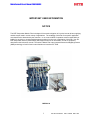
1
MATRIX FILTER
®
SERIES D
208-240 Volts, 60HZ
USER MANUAL
PART NO. INSTR –027
REL. 120628
REV. 006
© 2012 MTE Corporation
Matrix Series D User’s Manual 208-240 VAC
IMPORTANT USER INFORMATION
NOTICE
®
The MTE Corporation Matrix Filter is designed for harmonic mitigation of six pulse inverter drives supplying
variable torque loads in a wide variety of applications. The suitability of this filter for a specific application
must therefore be determined by the customer. In no event will MTE Corporation assume responsibility or
liability for any direct or consequential damages resulting from the use or application of this filter. Nor will
MTE Corporation assume patent liability with respect to the use of information, circuits or equipment
described in this instruction manual. The series D Matrix Filter uses patented Harmonics Mitigating Reactor
(HMR) technology to limit full load current distortion to less than 5% THID.
MDP0011A
1
Part No. INSTR-027 REL. 120628 REV. 006
Matrix Series D User’s Manual 208-240 VAC
TABLE OF CONTENTS
IMPORTANT USER INFORMATION .................................................................................................................................... 1
TABLE OF CONTENTS ....................................................................................................................................................... 2
IMPORTANT SAFETY INFORMATION ............................................................................................................................... 3
INTRODUCTION................................................................................................................................................................... 5
PART NUMBER CODES ...................................................................................................................................................... 6
SPECIFICATIONS: ............................................................................................................................................................... 7
AGENCY APPROVALS ........................................................................................................................................................... 7
RATINGS .............................................................................................................................................................................. 8
WATTS LOSS....................................................................................................................................................................... 8
REGULATION TABLE ............................................................................................................................................................. 9
CAPACITOR CURRENTS ...................................................................................................................................................... 10
OVER TEMPERATURE SWITCH RATINGS............................................................................................................................... 11
OPEN STYLE COMPONENT DIMENSIONS...................................................................................................................... 12
ENCLOSED UNIT SIZE AND WEIGHTS ........................................................................................................................... 13
PERFORMANCE DATA ..................................................................................................................................................... 14
LOAD EFFECT ON THID...................................................................................................................................................... 14
HARMONIC SPECTRUM 100% LOAD .................................................................................................................................... 14
POWER FACTOR ............................................................................................................................................................... 15
PERFORMANCE WITH UNBALANCED LINE VOLTAGE (TYPICAL) ................................................................................................ 15
ALTITUDE DERATING CURVE .............................................................................................................................................. 16
TEMPERATURE DERATING CURVE ....................................................................................................................................... 16
INSTALLATION INSTRUCTIONS ...................................................................................................................................... 17
HMR BOLT HOLE MOUNTING PATTERNS ............................................................................................................................. 18
CAP-PANEL BOLT HOLE MOUNTING PATTERNS .................................................................................................................... 19
HMR MOUNTING & TERMINAL LOCATIONS ............................................................................................................... 20
HMR 6 - 83 Amps ...................................................................................................................................................... 20
HMR 103 - 208 Amp .................................................................................................................................................. 21
HMR 240 Amp ........................................................................................................................................................... 22
CAP-ASSEMBLY MOUNTING & TERMINAL LOCATIONS ............................................................................................ 23
ENCLOSED UNIT INTERNAL DETAILS & TERMINAL LOCATIONS ............................................................................. 24
CAB-12C 6-21 AMPS .............................................................................................................................................. 24
CAB-17C 27-103 AMPS .......................................................................................................................................... 25
CAB-26C 128-240 AMPS ........................................................................................................................................ 26
CAB-26D 208-240 AMPS contactor options ........................................................................................................... 27
POWER WIRING CONNECTION ....................................................................................................................................... 28
INPUT AND OUTPUT TERMINAL SPECIFICATIONS ................................................................................................................... 30
OPEN PANEL UNIT INTERCONNECTION DIAGRAM .................................................................................................................. 31
ENCLOSED UNIT INTERCONNECTION DIAGRAM ..................................................................................................................... 32
FILTER DESCRIPTION ...................................................................................................................................................... 33
BLOCK DIAGRAM ............................................................................................................................................................... 34
MATRIX D BASIC SCHEMATIC DIAGRAM ............................................................................................................................... 35
CONTACTOR COIL SWITCHING CURRENTS ............................................................................................................................. 42
STARTUP....................................................................................................................................................................... 43
SEQUENCE OF OPERATION ................................................................................................................................................. 43
TROUBLESHOOTING ........................................................................................................................................................ 44
MTE MATRIX FILTER FIELD CHECKS ................................................................................................................................... 45
2
Part No. INSTR-027 REL. 120628 REV. 006
Matrix Series D User’s Manual 208-240 VAC
IMPORTANT SAFETY INFORMATION
WARNING
ONLY A QUALIFIED ELECTRICIAN CAN CARRY OUT THE ELECTRICAL INSTALLATION OF
THIS FILTER
WARNING
High voltage is used in the operation of this filter. Use Extreme caution to avoid contact with high
voltage when operating, installing or repairing this filter.
INJURY OR DEATH MAY RESULT IF SAFETY PRECAUTIONS ARE NOT OBSERVED.
After removing power, allow at least five minutes to elapse and verify that the capacitors have
discharged to a safe level before contacting internal components. Connect a DC voltmeter across
the capacitor terminals. Start with the meter on the highest scale and progressively switch to a
lower scale as the indicated voltage falls below the maximum value of the scale used.
WARNING
The opening of the branch circuit protective device may be an indication that a fault current has
been interrupted. To reduce the risk of fire or electrical shock, current-carrying parts and other
components of the filter should be examined and replaced if damaged.
3
Part No. INSTR-027 REL. 120628 REV. 006
Matrix Series D User’s Manual 208-240 VAC
IMPORTANT SAFETY INFORMATION, CONT.
WARNING
An upstream disconnect/protection device must be used as required by the National Electrical Code
(NEC) or governing authority.
WARNING
Even if the upstream disconnect/protection device is open, the drive down stream of the filter may
feed back high voltage to the filter. The drive safety instructions must be followed.
INJURY OR DEATH MAY RESULT IF SAFETY PRECAUTIONS ARE NOT OBSERVED
WARNING
The filter must be grounded with a grounding conductor connected to all grounding terminals.
WARNING
Only spare parts obtained from MTE Corporation or an authorized MTE distributor can be used.
WARNING
Loose or improperly secured connections may damage or degrade filter performance.
Visually inspect and secure all electrical connections before loading the filter.
4
Part No. INSTR-027 REL. 120628 REV. 006
Matrix Series D User’s Manual 208-240 VAC
Introduction
If the equipment is not going to be put into
service upon receipt, cover and store the
filter in a clean, dry location. After storage,
ensure that the equipment is dry and that
no condensation has accumulated on the
internal components of the filter before
applying power.
This manual was specifically developed to
assist in the installation, interconnection
and operation of the MTE Corporation
“Series D” Matrix Filter.
This manual is intended for use by
personnel experienced in the operation and
maintenance of electronic drives. Because
of the high voltages required by the filter
and drive and the potential dangers
presented by rotating machinery, it is
essential that all personnel involved in the
operation and maintenance of this filter
know and practice the necessary safety
precautions for this type of equipment.
Personnel should read and understand the
instructions contained in this manual before
installing, operating or servicing the filter
and the drive to which the filter is
connected.
Repair/Exchange Procedure
MTE Corporation requires a Returned
Material Authorization Number before it can
accept any filters that qualify for return or
repair. If problems or questions arise during
installation, setup, or operation of the filter,
please call the Director of Corporate Quality
for assistance at:
Phone: 262-946-2800
Upon Receipt of this Filter:
FAX: 262-253-8222
The MTE Matrix Filter has been subjected to
demanding factory tests before shipment.
Carefully inspect the shipping container for
damage that may have occurred in transit.
Then unpack the filter and carefully inspect
for any signs of damage. Save the shipping
container for future transport of the filter.
In the event of damage, please contact
and file a claim with the freight carrier
involved immediately.
5
Part No. INSTR-027 REL. 120628 REV. 006
Matrix Series D User’s Manual 208-240 VAC
PART NUMBER CODES
MD
X
____ X _ __
Matrix Series D
TYPE
P Panel mounts
G General Purpose NEMA 2
W Weather NEMA 3R
CURRENT RATING
0006 is 6 Amps
0240 is 240 Amps
VOLTAGE FREQUENCY CODE
A 208-240 Volts 60 HZ
C 385-415 volts 50 Hz
D 480 volts 60 Hz
E 600 volts 60- Hz
BLANK for Options shows none selected
ENCLOSURE OPTIONS
0 – None
1 – 3R / White paint
2 – 3R / Stainless / White paint
3 – Standard grey / rodent screen
4 – 3R / white paint / rodent screen
5 – 3R / Stainless / White / rodent screen
CONTACTOR OPTIONS
00 – None
02 – Contactor for capacitor Removal
09 – Adjustable Contactor capacitor removal
12 – Contactor for capacitor Removal / Transformer power
10 – Bypass contactor
11 – Bypass contactor / Transformer power
13 – Bypass contactor / Contactor for capacitor Removal / Transformer power
6
Part No. INSTR-027 REL. 120628 REV. 006
Matrix Series D User’s Manual 208-240 VAC
Specifications:
Service Conditions
Load: 6 pulse variable torque rectifier only
Input voltage: 208-240 VAC +/- 10%, 60 + 0.75 Hz, 3 phase
Input voltage line unbalance: 1% maximum
Maximum source impedance: 6.00%
Minimum source impedance: 1.5%
Service Factor: 1.00
Overload: 150 % for 1 minute duration with 10% output voltage reduction of nominal of voltage.
Ambient Temperature (Operating)
Enclosed Filters:
Open Panel Filters:
Storage Temperature:
-40 to +40 degrees C
-40 to +50 degrees C
-40 to +90 degrees C
Altitude: 0 to 3300 Feet above sea level. Refer to figure 4 for altitude de-rating.
Relative Humidity: 0 to 95% non-condensing
Agency Approvals
UL and cUL listed to UL508 Type MX and CSA-C22.2 No 14-95
File E180243 (3 – 1000 HP, 120VAC through 600 VAC
50, 50/60, 60 Hz Three Phase
Notes (SCCR):
1. The Short Circuit Current Rating (SCCR) is not required under Exception No.1 of UL508A SB4.2.1 effective 4/25/06. This exception also applies to all
the Contactor Options (002, 009, 012, and similar), where the Contactors are separated from the Main Power path by exempt components
(such as Reactors) of sufficient Impedance, which is assured in case of the Reactors that are integral components of our Filter.
2. The SCCR of Matrix Harmonic Filters with the Bypass Options (010, 011, 013, and similar) is determined by the rating of the Bypass Contactor, if the
Contactor is supplied by MTE. These Options use Eaton (Cutler-Hammer) Freedom Series Contactors. The Contactors are UL certified
as IEC Type 2, and have the SCCR of 100,000 Amps, when protected by appropriate Current Limiting Fuses (or Fast Acting Breaker of
similar characteristics), such upstream branch protection devices being supplied and installed by Others. Customer’s election to
substitute their own Contactor for MTE’s Standard, renders such Contactor separate from the Filter and thus has no impact on the Filter
Rating Exemption Status.
Performance
Total Harmonic Current Distortion:
Five Percent Filter: 5% MAX at FULL LOAD
Standby Current:
Without Optional Capacitor Contactor: 70% of the full load capacitor current listed in Table 3
With Optional Capacitor Contactor: Refer to Drive User’s Manual
7
Part No. INSTR-027 REL. 120628 REV. 006
Matrix Series D User’s Manual 208-240 VAC
Specifications - Continued
Ratings
Watts loss
Table 1
Maximum Output
Amps
RMS
Efficiency
(Typical)
(%)
Power Dissipation @
Rated Current
(Typical)
(Watts)
6
95.4
99
8
95.8
121
11
96.4
144
14
96.6
169
21
97.2
214
27
97.4
254
34
97.7
286
44
97.9
338
52
98.0
373
66
98.2
439
83
98.3
506
103
98.4
591
128
98.6
664
165
98.7
763
208
98.8
905
240
98.8
997
8
Part No. INSTR-027 REL. 120628 REV. 006
Matrix Series D User’s Manual 208-240 VAC
Specifications - Continued
Regulation table
Table 2
FILTER VOLTAGE REGULATION
208 VAC
240 VAC
MAXIMUM OUTPUT VOLTAGE AT
NO LOAD
RMS
PEAK
218
308
251
355
MINIMUM OUTPUT VOLTAGE AT
FULL LOAD
RMS
PEAK
200
282
230
324
*MAXIMUM PCC VOLTAGE WITH
6% SOURCE IMPEDANCE
RMS
PEAK
212
300
245
346
Note: PCC is the point of common coupling with the power distribution system
9
Part No. INSTR-027 REL. 120628 REV. 006
Matrix Series D User’s Manual 208-240 VAC
Specifications - Continued
Capacitor Currents
Table 3
Capacitor Current at Full Load
6
Capacitor Current
(Typical)
Amps RMS
2.3
8
3.1
11
4.2
14
5.4
21
8.1
27
10.4
34
13.1
44
16.9
52
20.0
66
25.4
83
31.4
103
39.6
128
49.2
165
63.4
208
79.9
240
92.2
Filter Current Rating Amps Rms
10
Part No. INSTR-027 REL. 120628 REV. 006
Matrix Series D User’s Manual 208-240 VAC
Specifications - Continued
Over Temperature Switch Ratings
Table 6
NC Switch opens at 180 Deg. +/- 5 deg C
Current Amps
Voltage
Contact Load
6
120 AC
Resistive Loads
3
120 AC
Inductive Loads
3
240 AC
Resistive Loads
2.5
240 AC
Inductive Loads
8
12 VDC
Resistive Loads
4
24 VDC
Resistive Loads
11
Part No. INSTR-027 REL. 120628 REV. 006
Matrix Series D User’s Manual 208-240 VAC
Specifications - Continued
Open Style Component Dimensions
HMR
Ref.
Figure
Amps
rating
Catalog Part
Number
Weight
Lbs.
HMR Size Inches
6
8
11
14
21
27
34
44
52
66
83
103
128
165
208
240
MDP0006A
MDP0008A
MDP0011A
MDP0014A
MDP0021A
MDP0027A
MDP0034A
MDP0044A
MDP0052A
MDP0066A
MDP0083A
MDP0103A
MDP0128A
MDP0165A
MDP0208A
MDP0240A
26
28
33
39
48
63
74
84
119
150
169
172
209
265
276
282
11.3''H x 6''W x 5.6''D
11.3''H x 6''W x 5.6''D
11.3''H x 6''W x 6.2''D
11.3''H x 6''W x 6.3''D
12.4''H x 7.2''W x 5.7''D
12.4''H x 7.3''W x 6.3''D
15.8''H x 9''W x 6.5''D
15.8''H x 9''W x 7''D
15.8''H x 9''W x 7''D
15.8''H x 9''W x 7.5''D
15.8''H x 9''W x 8''D
16.5''H x 12.3''W x 9.6''D
16.5''H x 12.3''W x 10.2''D
16.5''H x 12.3''W x 11.3''D
16.5''H x 12.3''W x 11''D
23''H x 15.3''W x 11.3''D
Figure 5
Figure 5
Figure 5
Figure 5
Figure 5
Figure 5
Figure 5
Figure 5
Figure 5
Figure 5
Figure 5
Figure 6
Figure 6
Figure 6
Figure 6
Figure 7
Capacitor assemblies
size Inches
5.6''H x 5.6''W x 9.3''D
5.6''H x 5.6''W x 9.3''D
5.6''H x 5.6''W x 7.3''D
5.6''H x 5.6''W x 8.2''D
5.6''H x 5.6''W x 9.3''D
8''H x 9.1''W x 12''D
8''H x 9.1''W x 12''D
8''H x 9.1''W x 12''D
5.6''H x 5.6''W x 9.3''D
8''H x 9.1''W x 12''D
8''H x 9.1''W x 12''D
8''H x 9.1''W x 12''D
12''H x 9.1''W x 12''D
12''H x 9.1''W x 12''D
15''H x 9.1''W x 12''D
15''H x 9.1''W x 12''D
Capacitor
Ref.
Figure
Figure 10
Figure 10
Figure 10
Figure 10
Figure 10
Figure 11
Figure 11
Figure 11
Figure 10
Figure 11
Figure 11
Figure 11
Figure 12
Figure 12
Figure 13
Figure 13
See following assembly pages for drawing details.
12
Part No. INSTR-027 REL. 120628 REV. 006
Matrix Series D User’s Manual 208-240 VAC
Specifications - Continued
Enclosed Unit Size and Weights
Table 5
Filter Amps
NEMA 2
Enclosure
Weight
NEMA 3R
Enclosure
Weight
Figure
6
MDG0006A
CAB-12C2
76
MDW0006A
CAB-12C3
86
Figure 14
8
MDG0008A
CAB-12C2
79
MDW0008A
CAB-12C3
89
Figure 14
11
MDG0011A
CAB-12C2
83
MDW0011A
CAB-12C3
93
Figure 14
14
MDG0014A
CAB-12C2
89
MDW0014A
CAB-12C3
99
Figure 14
21
MDG0021A
CAB-12C2
100
MDW0021A
CAB-12C3
110
Figure 14
27
MDG0027A
CAB-17C2
115
MDW0027A
CAB-17C3
125
Figure 15
34
MDG0034A
CAB-17C2
126
MDW0034A
CAB-17C3
136
Figure 15
44
MDG0044A
CAB-17C2
138
MDW0044A
CAB-17C3
148
Figure 15
52
MDG0052A
CAB-17C2
190
MDW0052A
CAB-17C3
199
Figure 15
66
MDG0066A
CAB-17C2
219
MDW0066A
CAB-17C3
228
Figure 15
83
MDG0083A
CAB-17C2
241
MDW0083A
CAB-17C3
250
Figure 15
103
MDG0103A
CAB-17C2
244
MDW0103A
CAB-17C3
253
Figure 15
128
MDG0128A
CAB-26C2
385
MDW0128A
CAB-26C3
406
Figure 16
165
MDG0165A
CAB-26C2
441
MDW0165A
CAB-26C3
462
Figure 16
208
MDG0208A
CAB-26C2
461
MDW0208A
CAB-26C3
482
Figure 16
240
MDG0240A
CAB-26C2
467
MDW0240A
CAB-26C3
488
Figure 16
Note: Weight is shown in pounds
13
Part No. INSTR-027 REL. 120628 REV. 006
Matrix Series D User’s Manual 208-240 VAC
Specifications - Continued
Performance Data
Figure 1
Load effect on THID
5% Filter THID vs. Load
9
8
Percent THID
7
6
5
4
3
2
1
0
0
20
40
60
80
100
Percent Load
Typical
Figure 2
Harmonic Spectrum 100% Load
Harmonic Current %
5% Matrix Filter Typical Harmonic
Spectrum For 100% Load
4
3
2
1
0
5
7
11
13
17
19
23
25
Harmonic order
14
Part No. INSTR-027 REL. 120628 REV. 006
Matrix Series D User’s Manual 208-240 VAC
Specifications - Continued
Figure 3
Power Factor
Power Factor
Filter Power Factor vs Load
Leading PF For All Loads
1.10
1.00
0.90
0.80
0.70
0.60
0.50
0.40
0.30
0.20
0
20
40
60
80
100
120
Percent Filter Load
Typical
Worst Case
Performance with Unbalanced Line Voltage (Typical)
Table 7
All Components at Nominal Values and Worse Case
Service Conditions
100% Load
Nominal THID
3.93%
1% Unbalance
4.06%
2% Unbalance
4.47%
3% Unbalance
5.10%
30% Load
Nominal THID
7.06%
1% Unbalance
7.45%
2% Unbalance
8.21%
3% Unbalance
10.46%
15
Part No. INSTR-027 REL. 120628 REV. 006
Matrix Series D User’s Manual 208-240 VAC
Altitude Derating Curve
Figure 4
Current De-Rating Factor
Altitude Derating Curve
1.05
1.00
0.95
0.90
0.85
0.80
0.75
0.70
0
3300
6600
9900
13200
16500
Altitude (Feet)
Temperature Derating Curve
Figure 4A
Series D Matrix Filter Temperature Derating Table
Filter Current Derating Factor
1
0.99
0.98
0.97
0.96
0.95
0.94
0.93
0.92
0.91
0.9
0
2
4
6
8
10
12
14
16
18
20
Temperature Above Rated Ambient Deg. C
Note: Contact factory if Ambient is 20 °C above temperature rating.
See or click Specifications for temperature ratings
16
Part No. INSTR-027 REL. 120628 REV. 006
Matrix Series D User’s Manual 208-240 VAC
The capacitor assembly must be located in
the lowest temperature regions of the
enclosure - generally toward the bottom and
away from high temperature components.
INSTALLATION INSTRUCTIONS
Matrix Filters are supplied in the following
mechanical configurations:
Panel mounted assemblies
Floor mounted general purpose NEMA 2,
& 3R cabinets,
Select a well-ventilated, dust-free area away
from direct sunlight, rain or moisture. Do not
install in or near a corrosive environment.
Avoid locations where the filter would be
subjected to excessive vibrations.
Figure’s 5 - 17 contain outline drawings for
the various ratings and show mounting
orientation with bolt patterns.
Panel mounted filters are designed for
mounting in the vertical plane within the
customer’s enclosure. Panel mount units are
made up of a Harmonic Mitigating Reactor
(HMR) and one or more capacitor panel
assemblies referred to as cap-panels on
drawings and diagrams.
Include the power dissipation of the filter
along with all the other components located in
the enclosure to determine the internal
temperature rise and cooling requirements of
the enclosure.
Mount the Harmonic Mitigating Reactor in a
location where the ambient temperature does
not exceed 50 degrees C. Allow a minimum
side clearance of four (4) inches and a
vertical clearance of six (6) inches for proper
heat dissipation and access.
WARNING
Do not install capacitor assembly
above/near resistors and
Harmonic Mitigating Reactor.
Premature or catastrophic failure
may occur.
17
General purpose NEMA 2, and 3R enclosed
filters are designed for floor mounting in the
vertical plane in an environment suitable for
the enclosure type. Do not install in or near a
corrosive environment. Avoid locations where
the filter would be subjected to excessive
vibrations. Allow a minimum side and back
clearance of eight (8) inches and front
clearance of thirty-six (36) inches for proper
heat dissipation and access.
Refer to Article 430 Table 430.91 of the
National Electrical code for the selection of
the appropriate enclosure Type Number for
your application.
Part No. INSTR-027 REL. 120628 REV. 006
Matrix Series D User’s Manual 208-240 VAC
Installation Instructions Continued
HMR Bolt Hole Mounting Patterns
Table 8
Part
Number
MDP0006A
11.3''H x 6''W x 5.6''D
Rear Mount
Centerline
10.25''A x 5''B
Base Mount
Centerline
3''C x 2.5''E
Mounting
Holes
0.281 DIA
Figure 5
28
11.3''H x 6''W x 5.6''D
10.25''A x 5''B
3''C x 2.5''E
0.281 DIA
Figure 5
MDP0011A
33
11.3''H x 6''W x 6.2''D
10.25''A x 5''B
3''C x 2.5''E
0.281 DIA
Figure 5
MDP0014A
39
11.3''H x 6''W x 6.3''D
10.25''A x 5''B
3''C x 2.5''E
0.281 DIA
Figure 5
MDP0021A
48
12.4''H x 7.2''W x 5.7''D
11.38''A x 5''B
3''C x 2.38''E
0.281 DIA
Figure 5
MDP0027A
63
12.4''H x 7.3''W x 6.3''D
11.38''A x 5''B
3''C x 2.88''E
0.281 DIA
Figure 5
MDP0034A
74
15.8''H x 9''W x 6.5''D
14.25''A x 6''B
4.26''C x 3.2''E
0.358 DIA
Figure 5
MDP0044A
84
15.8''H x 9''W x 7''D
14.25''A x 6''B
4.26''C x 3.75''E
0.358 DIA
Figure 5
MDP0052A
119
15.8''H x 9''W x 7''D
14.25''A x 6''B
4.26''C x 3.75''E
0.358 DIA
Figure 5
MDP0066A
150
15.8''H x 9''W x 7.5''D
14.25''A x 6''B
4.26''C x 4.25''E
0.358 DIA
Figure 5
MDP0083A
169
15.8''H x 9''W x 8''D
14.25''A x 6''B
4.26''C x 4.75''E
0.358 DIA
Figure 5
MDP0103A
172
16.5''H x 12.3''W x 9.6''D
12.24''A x 11''B
6.5''C x 11''E
0.413 DIA
Figure 6
MDP0128A
209
16.5''H x 12.3''W x 10.2''D
12.14''A x 11''B
6.5''C x 11''E
0.413 DIA
Figure 6
MDP0165A
265
16.5''H x 12.3''W x 11.3''D
12.15''A x 11''B
6.5''C x 11''E
0.413 DIA
Figure 6
MDP0208A
276
16.5''H x 12.3''W x 11''D
12.21''A x 11''B
6.5''C x 11''E
0.413 DIA
Figure 6
MDP0240A
282
23''H x 15.3''W x 11.3''D
17.83''A x 14''B
8''C x 14''E
0.413 DIA
Figure 7
Lbs
Overall Size
26
MDP0008A
Figure
Use the above table and referenced figures to establish suitable reactor mounting.
18
Part No. INSTR-027 REL. 120628 REV. 006
Matrix Series D User’s Manual 208-240 VAC
Installation Instructions Continued
Cap-panel Bolt Hole Mounting Patterns
Table 9
Part Number
CAP
P.N.
Cap-panel
Weight Lbs.
MDP0006A
MDP0008A
MDP0011A
MDP0014A
MDP0021A
MDP0027A
MDP0034A
MDP0044A
MDP0052A
MDP0066A
MDP0083A
MDP0103A
MDP0128A
MDP0165A
MDP0208A
MDP0240A
202
294
204
295
522
271
266
308
530
267
272
268
270
523
300
301
3.75
3.75
3.75
3.75
3.75
7.5
7.5
7.5
3.75
7.5
7.5
7.5
11.25
11.25
15
15
Overall Size
Rear Mount
Centerline
Mounting
Holes
Figure
5.6''H x 5.6''W x 9.3''D
5.06''A x 5.06''B
0.218
Figure 10
5.6''H x 5.6''W x 9.3''D
5.06''A x 5.06''B
0.218
Figure 10
5.6''H x 5.6''W x 7.3''D
5.06''A x 5.06''B
0.218
Figure 10
5.6''H x 5.6''W x 8.2''D
5.06''A x 5.06''B
0.218
Figure 10
5.6''H x 5.6''W x 9.3''D
5.06''A x 5.06''B
0.218
Figure 10
8''H x 9.1''W x 12''D
7.25''A x 4.5''B
0.218
Figure 11
8''H x 9.1''W x 12''D
7.25''A x 4.5''B
0.218
Figure 11
8''H x 9.1''W x 12''D
7.25''A x 4.5''B
0.218
Figure 11
5.6''H x 5.6''W x 9.3''D
5.06''A x 5.06''B
0.218
Figure 10
8''H x 9.1''W x 12''D
7.25''A x 4.5''B
0.218
Figure 11
8''H x 9.1''W x 12''D
7.25''A x 4.5''B
0.218
Figure 11
8''H x 9.1''W x 12''D
7.25''A x 4.5''B
0.218
Figure 11
12''H x 9.1''W x 12''D
11.25''A x 4.5''B
0.218
Figure 12
12''H x 9.1''W x 12''D
11.25''A x 4.5''B
0.218
Figure 12
15''H x 9.1''W x 12''D
14.25''A x 4.5''B
0.218
Figure 13
15''H x 9.1''W x 12''D
14.25''A x 4.5''B
0.218
Figure 13
Use the above table and referenced figures to establish suitable Cap-panel mounting
19
Part No. INSTR-027 REL. 120628 REV. 006
Matrix Series D User’s Manual 208-240 VAC
Installation Instructions Continued
HMR MOUNTING & TERMINAL LOCATIONS
HMR 6 - 83 Amps
Filters No Longer Ship
With Resistors
Figure 5
20
6 - 83 AMP
Part No. INSTR-027 REL. 120628 REV. 006
Matrix Series D User’s Manual 208-240 VAC
Installation Instructions Continued
HMR MOUNTING & TERMINAL LOCATIONS
HMR 103 - 208 Amp
Filters No Longer Ship
With Resistors
Figure 6
103 – 208 AMP
21
Part No. INSTR-027 REL. 120628 REV. 006
Matrix Series D User’s Manual 208-240 VAC
Installation Instructions Continued
HMR MOUNTING & TERMINAL LOCATIONS
HMR 240 Amp
Filters No Longer Ship
With Resistors
Figure 7
22
240 AMP
Part No. INSTR-027 REL. 120628 REV. 006
Matrix Series D User’s Manual 208-240 VAC
Installation Instructions Continued
CAP-ASSEMBLY MOUNTING & TERMINAL LOCATIONS
Figure 10
3 Caps
Figure 11
6 Caps
Figure 12
9 Caps
Figure 13
12 Caps
23
Part No. INSTR-027 REL. 120628 REV. 006
Matrix Series D User’s Manual 208-240 VAC
Installation Instructions Continued
ENCLOSED UNIT INTERNAL DETAILS & TERMINAL LOCATIONS
CAB-12C 6-21 AMPS
Filters No Longer Ship
With Resistors
Figure 14 6 - 21 AMP
Refer to the MTE website, www.mtecorp.com, for Detailed Specifications
Capacitor placement shown for illustrative purposes only
24
Part No. INSTR-027 REL. 120628 REV. 006
Matrix Series D User’s Manual 208-240 VAC
Installation Instructions Continued
ENCLOSED UNIT INTERNAL DETAILS & TERMINAL LOCATIONS
CAB-17C 27-103 AMPS
Filters No Longer Ship
With Resistors
Figure 15 27-103 AMP
Refer to the MTE website, www.mtecorp.com, for Detailed Specifications
Capacitor placement shown for illustrative purposes only
25
Part No. INSTR-027 REL. 120628 REV. 006
Matrix Series D User’s Manual 208-240 VAC
Installation Instructions Continued
ENCLOSED UNIT INTERNAL DETAILS & TERMINAL LOCATIONS
CAB-26C 128-240 AMPS
Filters No Longer Ship
With Resistors
Figure 16 128-240 AMP
Refer to the MTE website, www.mtecorp.com, for Detailed Specifications
Capacitor placement shown for illustrative purposes only
26
Part No. INSTR-027 REL. 120628 REV. 006
Matrix Series D User’s Manual 208-240 VAC
Installation Instructions Continued
ENCLOSED UNIT INTERNAL DETAILS & TERMINAL LOCATIONS
CAB-26D 208-240 AMPS contactor options
Filters No Longer Ship
With Resistors
Figure 17 208-240 AMP
Refer to the MTE website, www.mtecorp.com, for Detailed Specifications
Capacitor placement shown for illustrative purposes only
27
Part No. INSTR-027 REL. 120628 REV. 006
Matrix Series D User’s Manual 208-240 VAC
Installation Instructions Continued
Power Wiring Connection
WARNING
Input and output power wiring to the filter
should be performed by authorized
personnel in accordance with the NEC and
all local electrical codes and regulations.
Cable lugs and mounting hardware are
provided by the customer.
Verify that the power source to which the
filter is to be connected is in agreement with
the nameplate data on the filter. A fused
disconnect switch or circuit breaker should
be installed between the filter and its source
of power in accordance with the
requirements of the NEC and all local
electrical codes and regulations. Refer to
the drive user manual for selection of the
correct fuse rating and class.
The filter is suitable for use on a circuit
capable of delivering not more than 100K
RMS symmetrical amperes at 480 volts
maximum when protected by type J, T or
RK1 class fuses or a circuit breaker having
a interrupting rating not less than 100K
RMS symmetrical amperes, 480 volts
maximum.
For filters supplied in general purpose
NEMA, 2 & 3R cabinets, interconnection
between the filter, its power source, and the
drive is shown in Figure 25. Refer to Figures
5 to 7 for the location of input, output,
ground, and over temperature switch
terminals. Table 10 lists the wire range and
terminal torque requirements as a function
of filter current ratings. Refer to the drive
user manual for instructions on
interconnecting the drive and motor and the
correct start-up procedures for the drive.
Wiring checks
Using Figure 27 visually check the wired
components for wiring errors then with a
multi meter check phase to phase isolation
using the 100 K ohm range. The multi meter
will read the parallel equivalent of the
bleeder resistors after the capacitors initially
charge. All phase to phase resistance
values should be the same.
WARNING
For panel mounted filter applications
interconnection between the filter, its power
source the cap-panels and the drive is
shown in Figure 24. Table 10 lists the wire
range and terminal torque requirements as
a function of filter current ratings. Use table
10 for selecting conductors that interconnect
the HMR and capacitor assemblies. Filters
that use multiple cap-panels share total cap
current shown on table 3.
Refer to the drive user manual for
instructions on interconnecting the drive and
motor and the correct start-up procedures
for the drive.
Any extremely low or high resistance
readings indicate a mis-wire and may
result in damage to filter components if
not corrected.
Check for the following faults:
Resistors wired phase to phase
Capacitor shorted
Capacitor bus not connected
Capacitor bus to chassis short
Paralleling wiring errors
The filter is designed for use with copper
conductors with a minimum temperature
rating of 75 degrees C.
28
Part No. INSTR-027 REL. 120628 REV. 006
Matrix Series D User’s Manual 208-240 VAC
Installation Instructions Continued
Power Wiring Connection, Cont.
Grounding and Ground Fault Protection
The filter must always be grounded with a
grounding conductor connected to all
ground terminals.
Due to high leakage currents associated
with variable frequency drives, ground fault
protective devices do not necessarily
operate correctly when placed ahead of a
Matrix Filter feeding a drive. When using
this type of device, its function should be
tested in the actual installation.
Over Temperature Switch
The temperature switch is provided to
annunciate adverse filter heating. Damage
to the filter or drive may be avoided by
interlocking this switch to shut down the
drive or illuminate a service light; see
figures 24 and 25 for connection diagrams.
Read the vendor drive manual for details in
using interlock inputs.
29
Part No. INSTR-027 REL. 120628 REV. 006
Matrix Series D User’s Manual 208-240 VAC
Installation Instructions Continued
Input and Output Terminal Specifications
Table 10
Cappanel Terminals
U4-V4-W4
HMR Terminals
Filter
Rating
(Amps)
6
8
11
14
21
27
34
44
52
66
83
103
128
165
208
240
Input /Output Power
U1-V1-W1 / U2-V2-W2
Wire Range
(AWG)
14 – 4
14 – 4
14 – 4
14 – 4
14 – 4
14 – 4
14 – 4
14 – 4
14 – 4
Flat copper tab
Flat copper tab
Flat copper tab
Flat copper tab
Flat copper tab
Flat copper tab
Flat copper tab
Terminal Torque
(in-lbs.)
16
16
16
16
16
16
16
16
16
N/A
N/A
N/A
N/A
N/A
N/A
N/A
U4-V4-W4
interconnect
cappanel
Terminal Torque
(in-lbs.)
16
16
16
16
16
16
16
16
16
16
16
16
16
16
50
50
CAPPANEL
Part
Number
Minimum
Interconnect
Wire Gauge
(AWG)
Terminal
Torque
(in-lbs.)
202
294
204
295
522
271
266
308
530
267
272
268
270
523
300
301
14
14
14
14
14
14
14
12
12
10
8
8
8
6
4
2
16
16
16
16
16
35
35
35
16
35
40
40
40
45
45
50
Note: Cappanel interconnect wiring specification according to UL508 75° C Table.
Note: To prevent flexing or bending of the coil windings attached to MHR Flat copper terminal
tabs, use two wrenches to tighten customer provided cable mounting hardware.
30
Part No. INSTR-027 REL. 120628 REV. 006
Matrix Series D User’s Manual 208-240 VAC
Installation Instructions Continued
Open Panel Unit Interconnection Diagram
Figure 24
Note: all 208-240 filters use only one cappanel assembly
31
Part No. INSTR-027 REL. 120628 REV. 006
Matrix Series D User’s Manual 208-240 VAC
Installation Instructions Continued
Enclosed Unit interconnection Diagram
Figure 25
32
Part No. INSTR-027 REL. 120628 REV. 006
Matrix Series D User’s Manual 208-240 VAC
FILTER DESCRIPTION
The MTE Matrix Filter is a low pass filter
containing proprietary technology, which
makes it particularly useful for harmonic
mitigation of adjustable speed drives. Figure
21 shows a block diagram of the filter.
Three phase AC power is connected to the
Harmonic Mitigating reactor HMR section
which contains patented circuitry which
inhibits oscillation of the filter with the AC
power system. Shunt resistors and
capacitor panels make up the rest of the
filter. Because of the capacitor bank the
filter operates with leading power factor at
light loads, but unlike trap filters the MTE
Matrix Filter does not produce significant
voltage rise at the point of common coupling
with the power system.
For constant torque, AC and DC drive
applications operating from six pulse
rectifier front ends selected a filter current
rating according to application engineering
note “Matrix Filter Operation in Constant
Torque Applications with Six Pulse
Rectifiers” or consult MTE engineering. For
phase controlled DC drive applications,
select filter current rating per application
note “Matrix Filter with Phase Controlled DC
Drivers”.
Matrix Filters are suitable for use with AC
and DC drives and they can be used in both
regenerative and non-regenerative
applications when properly selected. For AC
regenerative drives application consult the
factory.
Because the filter supplies harmonic
currents required by the drive, linear loads
(such as space heaters, incandescent
lighting and AC motors operated across the
line) should not be connected to the output
of the filter.
Where a single filter is used to feed multiple
drives, the output current rating of the filter
should be selected to equal the total current
rating of the individual drives when
calculated according to the instructions
above.
Filters for variable torque AC drives rated
7.5 HP and above should be selected for a
filter output current rating greater than or
equal to the motor current rating. If the
motor current rating is not available, use the
NEC motor current rating.
Filters for variable torque AC drives rated 2
– 5 HP should be selected for a filter output
current rating greater than or equal to 105%
of the motor current rating. If the motor
current rating is not available, select on the
basis of 105% of the NEC motor current
rating.
Filters for variable torque AC drives rated
less than 1.5 HP should be selected for an
output current rating greater than or equal to
110% of the motor current rating or 110%
OF the NEC motor current rating.
33
Part No. INSTR-027 REL. 120628 REV. 006
Matrix Series D User’s Manual 208-240 VAC
Filter Description -continued
Block Diagram
Figure 26
Note: Connect 208 or 240 volt power as indicated above in place of 480 V 60Hz.
34
Part No. INSTR-027 REL. 120628 REV. 006
Matrix Series D User’s Manual 208-240 VAC
Filter Description -continued
Matrix D Basic Schematic Diagram
Figure 27
35
Part No. INSTR-027 REL. 120628 REV. 006
Matrix Series D User’s Manual 208-240 VAC
Filter Description -continued
Contactor Options
Option -002
Capacitor Contactor
This option provides a contactor to disconnect the filter capacitor bank when the drive is not running. The
contactor is supplied with NO/NC auxiliary contacts. The contactor coil and auxiliary contacts are wired to
a customer terminal block. See page 39 for contactor coil switching characteristics. This option is
provided pre-wired complete for enclosed filters and as loose parts for open panel filters.
The above contactor option diagram is provided to help understand the circuit function
and does not reflect actual circuit wiring.
36
Part No. INSTR-027 REL. 120628 REV. 006
Matrix Series D User’s Manual 208-240 VAC
Filter Description -continued
Option -009
Capacitor Contactor with adjustable pick up and drop out
This option provides a contactor to disconnect the filter capacitor bank based on the motor load current.
Two current operated switches provide independent adjustment of the pickup and drop current levels.
The switches are preset at the factory for pick up at 35% and drop out at 20% of the filter output current
rating. The switches are each field adjustable over a 0 – 100% current range. This option is only available
for enclosed filters and may include a larger cabinet to accommodate the contactor and parts associated
with this option.
The above contactor option diagram is provided to help understand the circuit function
and does not reflect actual circuit wiring.
37
Part No. INSTR-027 REL. 120628 REV. 006
Matrix Series D User’s Manual 208-240 VAC
Filter Description -continued
Option -012
Capacitor contactor with control transformer
This option provides a control transformer to power the capacitor contactor. The contractor is provided
with NO/NC auxiliary contacts. For filter ratings 165 amps and above a pilot relay is also provided to limit
inrush current below 0.60 amps. Connections are wired to a customer terminal block. This option is only
available for enclosed filters and may include a larger cabinet to accommodate the contactor and parts
associated with this option.
The above contactor option diagram is provided to help understand the circuit function
and does not reflect actual circuit wiring.
38
Part No. INSTR-027 REL. 120628 REV. 006
Matrix Series D User’s Manual 208-240 VAC
Filter Description -continued
Option -010
Filter Bypass
The filter bypass option is designed to provide filter bypass for drives that have an integrated bypass
option as typically found in HVAC applications. Filter bypass is initiated by a contact closure when the
motor is switched to operate directly from the AC line instead of the drive. See page 42 for contactor coil
switching characteristics. A 120VAC control power source is required. This option is only available for
enclosed filters and may include a larger cabinet to accommodate the contactor and parts associated with
this option.
Option -011
Filter Bypass with transformer
The filter bypass option is designed to provide filter bypass for drives that have an integrated bypass
option as typically found in HVAC applications. Filter bypass is initiated by a contact closure when the
motor is switched to operate directly from the AC line instead of the drive. A control transformer provides
120 VAC power for contactor operation.. See page 42 for contactor coil switching characteristics. This
option is only available for enclosed filters and include a larger cabinet to accommodate the contactor
and parts associated with this option.
Filters rated 44 Amps and below
Filters rated 55 Amps and above
The above contactor option diagram is provided to help understand the circuit function
and does not reflect actual circuit wiring.
39
Part No. INSTR-027 REL. 120628 REV. 006
Matrix Series D User’s Manual 208-240 VAC
Filter Description -continued
Option -013
Filter bypass and capacitor contactor with control transformer
This option provides a 120 VAC control transformer to power the capacitor and bypass contactors.
Contractors are provided with NO/NC auxiliary contacts. For filter ratings 44 amps and above pilot relays
are also provided to limit inrush currents below 0.60 amps. A jumper selection provides single contact
switching for normal bypass control with capacitor removal. Connections are wired to a customer terminal
block.
This option is only available for enclosed filters and may include a larger cabinet to accommodate the
contactor and parts associated with this option.
The above contactor option diagram is provided to help understand the circuit function
and does not reflect actual circuit wiring.
40
Part No. INSTR-027 REL. 120628 REV. 006
Matrix Series D User’s Manual 208-240 VAC
Filter Description -continued
MTE BY-PASS option 010, 011 and 013
Warning!!!
Equipment damage may result from activation of the bypass contactor during motor operation.
Ensure the motor is at rest before switching the bypass control contactor!
Purpose: Provide compatible hardware to integrate a system motor bypass when used in conjunction with
a drive which supports the bypass function as required for HVAC and control applications.
1.) To switch out the Matrix Filter and connect utility power to the Matrix output terminals to
support a motor bypass initiated from the control contact of the drive.
2.) During the bypass mode, remove the effect of Matrix Filter capacitor loading on drive utility
branch circuits
Design:
For low current Matrix Filters a single contactor CR1 provides the dual function switching to accomplish
bypassing the Matrix Filter and removal of the filter’s capacitors. For higher current filters a second
powered contactor CR2 connects the capacitors to the filter circuit. See the schematic drawings that show
these circuits.
Function description:
1.) (Matrix Filter mode): The bypass coil CR1 is de-energized: the Matrix Filter provides normal
harmonic attenuation of the VFD distorted power. For the dual contactor systems the capacitor
contactor CR2 must be powered to get maximum THID reduction.
2.) With 120 VAC 60 Hz on CR1 from the customer supplied contact selection:
A three phase connection is made across the Matrix Filter input to the corresponding output
terminals. At the same time CR1 auxiliary contacts or the second CR2 contactor remove the
capacitors from the filter circuit.
41
Part No. INSTR-027 REL. 120628 REV. 006
Matrix Series D User’s Manual 208-240 VAC
Filter Description -continued
Contactor coil switching currents
Table 11
Options 002, 010 &011
The following table indicates the 120 VAC 60 Hz current required to switch and hold the various size
contactors used in Matrix Filter capacitor switching and bypass options. This data is provided to select the
proper switch rating to remotely control the contactor.
Contactor Currents for 120 VAC 60 Hz coils.
Matrix filter current
Rating
AMPS
6
8
11
14
21
27
34
44
52
66
83
103
128
165
208
240
Capacitor Contactor Option 002
AMPS (Maximum)
INRUSH
SEALED
0.62
0.62
0.62
0.62
0.62
0.62
0.62
0.62
0.62
0.62
0.62
0.62
0.54
1.70
2.88
1.42
0.048
0.048
0.048
0.048
0.048
0.048
0.048
0.048
0.048
0.048
0.048
0.048
0.064
0.30
0.25
0.026
42
Filter Bypass Options 010 & 011
AMPS (Maximum)
INRUSH
SEALED
1.25
1.25
1.25
1.25
1.25
1.25
1.25
1.55
2.33
3.5
3.5
2.04
2.34
3.78
4.76
3.5
0.090
0.090
0.090
0.090
0.090
0.090
0.090
0.112
0.352
0.30
0.30
0.74
0.95
1.73
0.286
0.062
Part No. INSTR-027 REL. 120628 REV. 006
Matrix Series D User’s Manual 208-240 VAC
Filter Description -continued
STARTUP
3. Check that moisture has not condensed
on the filter components. If moisture is
present, do not proceed with startup
until the moisture has been removed.
4. Disconnect the filter output from the
drive.
5. Connect the filter to the utility.
Safety Precautions
Before startup, observe the following
warnings and instructions:
WARNING
Internal components of the filter are at
line potential when the filter is connected
to the utility. This voltage is extremely
dangerous and may cause death or
severe injury if you come in contact with
it.
WARNING
Use extreme caution to avoid contact
with line voltage when checking for
power. INJURY OR DEATH MAY RESULT
IF SAFETY PRECAUTIONS ARE NOT
OBSERVED.
WARNING
6. Confirm that line voltage is present at
the input terminals (U, V1, W1) of the
filter.
7. Confirm that line voltage is present at
the output terminals (U2, V2, W2) of the
filter.
8. Disconnect the filter from the utility.
9. Connect the filter output to the drive.
10. Refer to the drive user manual for the
drive startup procedure. Observe all
safety instructions in the drive user
manual.
After disconnecting the utility power,
wait at least 5 minutes before doing any
work on the filter connections. After
removing power, allow at least five
minutes to elapse and verify that the
capacitors have discharged to a safe
level before contacting internal
components. Connect a DC voltmeter
across the capacitor terminals. Start
with the meter on the highest scale and
progressively switch to a lower scale as
the indicated voltage falls below the
maximum value of the scale used.
WARNING
Sequence of Operation
INJURY OR DEATH MAY RESULT IF THE
DRIVE SAFETY PRECAUTIONS ARE NOT
OBSERVED.
1. Read and follow safety precautions.
2. After installation, ensure that:
• All filter ground terminals are
connected to ground.
• Power wiring to the utility, drive and
motor is in accordance with the
power wiring connection diagrams
shown in installation instructions
section. Use the guidelines of table
10 for power and cap-panel wire
gauges.
WARNING
Damage to equipment may occur if the drive
startup procedures are not observed.
43
Part No. INSTR-027 REL. 120628 REV. 006
Matrix Series D User’s Manual 208-240 VAC
STARTUP - CONTINUED
TROUBLESHOOTING
WARNING
WARNING
When properly installed, this equipment
has been designed to provide maximum
safety for operating personnel. However,
hazardous voltages exist within the
confines of the enclosure. Servicing should
therefore be performed by qualified
personnel only and in accordance with
OSHA Regulations.
High voltage is used in the operation of this
filter. Use Extreme caution to avoid contact
with high voltage when operating, installing
or repairing this filter. INJURY OR DEATH
MAY RESULT IF SAFETY PRECAUTIONS
ARE NOT OBSERVED.
To aid in troubleshooting, a block diagram is
shown in Figure 21 and a list of potential
problems and solutions are listed below.
44
After removing power, allow at least five
minutes to elapse and verify that the
capacitors have discharged to a safe level
before contacting internal components.
Connect a DC voltmeter across the
capacitor terminals. Start with the meter on
the highest scale and progressively switch
to a lower scale as the indicated voltage
falls below the maximum value of the scale
used.
Part No. INSTR-027 REL. 120628 REV. 006
Matrix Series D User’s Manual 208-240 VAC
STARTUP - CONTINUED
Troubleshooting, Cont.
MTE Matrix Filter Field Checks
1. Read and understand the voltage appropriate MTE Matrix user manual. These manuals may be
downloaded from the www.mtecorp.com web site. Locate figures and drawings for your particular
filter and identify the terminals locations.
2. Disconnect all power and remove input power wiring from U1, V1, W1 terminals.
3. Remove VFD drive power connections from filter terminals U2, V2, W2 and any contactor or
temperature switch wiring. (For filters having control transformers: remove power fuses on top of
transformer.)
4. Visually inspect filter terminals and wiring lugs for signs of heat and corrosion. Contact factory if any
wires appear to be missing or cut!
5. Inspect the U4, V4, W4 capacitor interconnect terminals and wiring.
6. Visually inspect all capacitors for signs of case deformation bowing of the top, leaking oil or terminal
damage. Note the CAP- # and date code of any damaged capacitors.
7. Using a multi meter set to read 100K ohms check:
a. Phase to phase U1-V1-W1-U1 (mechanically activate contactor if present) after reactor and
caps charge reading should be about 40K (total equivalent breeder resistance value) and
should be the same for each phase. Open circuit or very low readings indicate a problem.
b. Phase to chassis U1- case, V1-case, W1- case; low readings indicate a ground fault problem.
8. Ensure the “disconnect” is safe then wire the utility power to U1, V1, W1.
9. Apply power and verify that proper output voltage is present on U2, V2, and W2.
10. Using a clamp on amp meter read the filter input current:
a. Readings will be 0.7 of the capacitor current listed in table 3 for the listed filter current in the
user manual (mechanically activate the contactor if the filter is equipped with one). Readings
should be the same (+/- 5%) for all phase currents; contact the factory if currents are out
of tolerance!
b. Open contactor readings will show zero current for all phases.
11. Disconnect filter power and wire the VFD to U2, V2, and W2 as well as any control wiring to the filter
contactor or temperature switch. Replace any control transformer fuses. Follow the drive power
startup guidelines in the drive manufactures user manual.
45
Part No. INSTR-027 REL. 120628 REV. 006
Matrix Series D User’s Manual 208-240 VAC
STARTUP - CONTINUED
PROBLEM:
Line voltage is not present at the filter output terminals.
Possible cause:
Power to the filter is turned off.
Solution:
Turn power on.
Possible cause:
One or more external line fuses are blown.
Solution:
Verify the continuity of line fuses in all phases. Replace as necessary.
PROBLEM:
Full Load Harmonic current distortion exceeds 5% on one or more
phases at full load.
Possible cause:
The capacitor assembly has not been connected.
Solution:
Check interconnection of capacitor assembly with HMR (Figure 19 & 20).
Possible cause:
A capacitor has failed.
Solution:
Inspect the tops of all capacitors for bowing. Replace failed capacitors.
Possible cause:
Source impedance is less than 1.5%.
Solution
Add a minimum 1.5% impedance line reactor to the filter input
Possible cause:
Input source voltage harmonic distortion.
Solution
Identify equipment causing harmonic voltage distortion and add filters as
required or accept elevated THVD
Possible cause:
Line voltage unbalance exceeds 1%.
Solution:
Balance input line voltage to 1% or less.
46
Part No. INSTR-027 REL. 120628 REV. 006
Matrix Series D User’s Manual 208-240 VAC
STARTUP - CONTINUED
PROBLEM:
Filter output voltage is not within specification
Possible cause:
Filter input voltage is not within specification.
Solution:
Check the AC input line voltage and verify that it is within tolerance. Refer
to the filter service conditions and performance specifications for
tolerances.
Possible cause:
Source impedance is out of tolerance.
Solution:
Verify that the source impedance is within tolerance. Refer to the filter
service conditions and performance specifications for tolerances.
Possible cause:
One or more Capacitors is damaged
Solution:
Visually check capacitor top for distortion or doming check for shorts or
open caps.
Possible cause:
Drive set up parameters do not allow for input filter
Solution:
Consult drive manufacturer to update setup to accommodate input filter
Possible cause:
Input voltage subject to extreme transients such as switching between two
voltage sources. Drive faults on over or under voltage.
Solution:
Source switching is not recommended without proper phase synchronizing
or allowing reasonable time delay before transfer to new source.
47
Part No. INSTR-027 REL. 120628 REV. 006
Matrix Series D User’s Manual 208-240 VAC
STARTUP - CONTINUED
Matrix Filter Series D 208-240V 60Hz User Manual
INSTR-027
Responsibility: Product Lines Manager
Approved By: Wayne Walcott
ISO Section:
7.2.3
Revision
081020
Date
10/20/08
110302
03/02/11
110419
004
04/19/11
06/08/11
005
05/01/12
006
06/28/12
Revision History
New document written by Wayne Walcott per ECN 6065
Updated Table 10, Fax number, and MTE logo. Added hyperlinks to tables.
Added Warning Symbols. Added cappanel warning text. Fixed numerous
spelling and grammar errors.
Updated table 10,cappanel listing
Modified Revision scheme to match Avante
Cosmetic change to Figure 27. Updated drawings for contactor options 002,
010, 011, 012 and 013 to clarify customer supplied components.
By LB. Updated logo. Added “No Resistors” note to drawings.
48
Part No. INSTR-027 REL. 120628 REV. 006