1
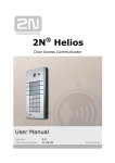
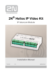
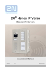
2N® Helios IP Vario
Door Entry IP Intercom
Installation Manual
Version
2.3
www.2n.cz
The 2N TELEKOMUNIKACE a.s. is a Czech manufacturer and supplier of telecommunications
equipment.
The product family developed by 2N TELEKOMUNIKACE a.s. includes GSM gateways, private
branch exchanges (PBX), and door and lift communicators. 2N TELEKOMUNIKACE a.s. has
been ranked among the Czech top companies for years and represented a symbol of
stability and prosperity on the telecommunications market for almost two decades. At
present, we export our products into over 120 countries worldwide and have exclusive
distributors on all continents.
2N® is a registered trademark of 2N TELEKOMUNIKACE a.s. Any product and/or other
names mentioned herein are registered trademarks and/or trademarks or brands protected
by law.
2N TELEKOMUNIKACE a.s. administers the FAQ database to help you quickly find
information and to answer your questions about 2N products and services. On
www.faq.2n.cz you can find information regarding products adjustment and instructions for
optimum use and procedures „What to do if...“.
2N TELEKOMUNIKACE a.s. hereby declares that the 2N ® Helios IP Vario product complies
with all basic requirements and other relevant provisions of the 1999/5/EC directive. For
the full wording of the Declaration of Conformity see the CD-ROM (if enclosed) or our
website at www.2n.cz.
This device complies with part 15 of the FCC Rules. Operation is subject to the following
two conditions: (1) This device may not cause harmful interference, and (2) this device
must accept any interference received, including interference that may cause undesired
operation.
The 2N TELEKOMUNIKACE a.s. is the holder of the ISO 9001:2009 certificate. All
development, production and distribution processes of the company are managed by this
standard and guarantee a high quality, technical level and professional aspect of all our
products.
Content
Content
1. Product Overview . . . . . . . . . . . . . . . . . . . . . . . . . . . . . . . . . . 4
1.1 Components and Associated Products . . . . . . . . . . . . . . . . . . . . . . . . . . . . . . . 6
1.2 Terms and Symbols . . . . . . . . . . . . . . . . . . . . . . . . . . . . . . . . . . . . . . . . . . . . . . 18
2. Description and Installation . . . . . . . . . . . . . . . . . . . . . . . . . . 19
2.1 Before You Start . . . . . . . . . . . . . . . . . . . . . . . . . . . . . . . . . . . . . . . . . . . . . . . . . 20
2.2 Mechanical Installation . . . . . . . . . . . . . . . . . . . . . . . . . . . . . . . . . . . . . . . . . . . . 21
2.3 Electric Installation . . . . . . . . . . . . . . . . . . . . . . . . . . . . . . . . . . . . . . . . . . . . . . . 30
2.4 Completion . . . . . . . . . . . . . . . . . . . . . . . . . . . . . . . . . . . . . . . . . . . . . . . . . . . . . 41
2.5 Extending Module Connection . . . . . . . . . . . . . . . . . . . . . . . . . . . . . . . . . . . . . . 43
3. Function and Use . . . . . . . . . . . . . . . . . . . . . . . . . . . . . . . . . . 56
3.1 Configuration . . . . . . . . . . . . . . . . . . . . . . . . . . . . . . . . . . . . . . . . . . . . . . . . . . . 57
3.2 Intercom Control as Viewed by External User . . . . . . . . . . . . . . . . . . . . . . . . . . 62
3.3 Display-Equipped Intercom as Viewed by External User . . . . . . . . . . . . . . . . . . 65
3.4 Intercom Control as Viewed by Internal User . . . . . . . . . . . . . . . . . . . . . . . . . . . 68
3.5 Maintenance . . . . . . . . . . . . . . . . . . . . . . . . . . . . . . . . . . . . . . . . . . . . . . . . . . . . 70
4. Technical Parameters . . . . . . . . . . . . . . . . . . . . . . . . . . . . . . . 71
5. Supplementary Information . . . . . . . . . . . . . . . . . . . . . . . . . . 73
5.1 Troubleshooting . . . . . . . . . . . . . . . . . . . . . . . . . . . . . . . . . . . . . . . . . . . . . . . . . 74
5.2 Directives, Laws and Regulations . . . . . . . . . . . . . . . . . . . . . . . . . . . . . . . . . . . 75
5.3 General Instructions and Cautions . . . . . . . . . . . . . . . . . . . . . . . . . . . . . . . . . . . 77
1. Product Overview
Here is what you can find in this section:
1.1 Components and Associated Products
1.2 Terms and Symbols
Basic Features
2N® Helios IP Vario is a highly reliable IP door access intercom provided with a lot of
useful above-standard functions. Supporting the SIP standard and being compatible
with the leading IP PBX and telephone suppliers, 2N® Helios IP Vario can make use
of all VoIP services.
2N® Helios IP Vario can be equipped with a colour camera, which displays the calling
person on the called party's video telephone or PC monitor.
2N® Helios IP Vario can be provided with up to 54 pre-programmed buttons. You can
set up to three telephone numbers and time profiles for each of the buttons to increase
the accessibility of the called party.
2N® Helios IP Vario can be equipped with a numerical keypad to be used as a code
lock for lock switch activating or telephone/subscriber number dialling.
2N® Helios IP Vario is equipped with an electric lock switch. You can control the
switch using a numerical keypad or, during a call, using any telephone set. An
additional switch module can be installed if necessary. A wide range of settings allow
for a variety of applications.
2N® Helios IP Vario can also be provided with RFID card reader modules.
2N® Helios IP Vario is very easy to install. All you have to do is connect the system
into your LAN via a network cable and feed it from a 12 V power supply or your PoE
supporting LAN.
Configure 2N® Helios IP Vario using your PC via any web browser. Use the IP
2N® TELEKOMUNIKACE a.s., www.2n.cz
4
Manager to manage extensive 2N® Helios IP Vario systems easily and quickly.
Advantages of Use
Bidirectional communication – acoustic echo cancelling
Integrated colour camera
Optional dial buttons including name tags with backlight
Optional numerical keypad with backlight
Integrated electronic lock switches with wide setting options
Optional integrated RFID card reader module
LAN (PoE) or external 12 V power supply
Configuration via web interface or dedicated PC application
SIP 2.0 support
Up to 54 buttons pre-programmed buttons
Up to 1999 telephone directory positions
Up to 20 user time profiles
Video codecs (H.263, H.263+, H.264, MPEG-4, JPEG)
Audio codecs (G.711, G.729, G.722, L16/16kHz)
HTTP server for configuration
SNTP client for time synchronisation with server
RTSP server for video streaming
SMTP client for e-mail sending
TFTP client for automatic configuration and firmware update
2N® TELEKOMUNIKACE a.s., www.2n.cz
5
1.1 Components and Associated Products
Basic Units
2N® TELEKOMUNIKACE a.s., www.2n.cz
6
Part
No. 9137111(C)U
Part
No. 9137131(C)U
Part
No. 9137161(C)U
1 button
3 buttons
6 buttons
control of one
electric lock
control of one
electric lock
control of one
electric lock
possibility of
connecting card
reader, extenders or
information panel or
additional switch
possibility of
connecting card
reader, extenders or
information panel or
additional switch
possibility of
connecting card
reader, extenders or
information panel or
additional switch
Part
Part
Part
Part
No. 9137160(C)KDU
No. 9137111(C)KU No. 9137131(C)KU No. 9137161(C)KU
6 buttons
1 button
3 buttons
6 buttons
graphic display
keypad
keypad
keypad
keypad
control of one
control of one
control of one
control of one electric
electric lock
electric lock
electric lock
lock
possibility of
possibility of
possibility of
possibility of
connecting card
connecting card
connecting card
connecting card
reader, extenders or reader, extenders or reader, extenders or
reader, extenders or
information panel or information panel or information panel or
information panel or
additional switch
additional switch
additional switch
additional switch
2N® TELEKOMUNIKACE a.s., www.2n.cz
7
(C) = integrated camera
Extending Modules
Part No. 9135181E
Extending module
8 buttons
Dimension of the module 100
x 210 x 29 mm
2N® TELEKOMUNIKACE a.s., www.2n.cz
Part No. 9135182E
Extending module
16 buttons
Dimension of the module 100
x 210 x 29 mm
Part No. 9135310E
Info panel
Backlit panel without
buttons; used
for insertion of a
telephone directory,
company logo, house
number, etc.
8
Extenders
Part No. 9135301E
Spare button name plate
Part No. 9135311E
Info panel – name plate
Replacing cover for four name tags.
Helps you use a half of the extending
module for insertion of a telephone directory,
working hours, etc.
Part No. 9135302E
Spare double-button name plate
Tip
All units can be surface mounted without needing any additional
accessories.
To make them even more robust and resistant, use a Vandal Resistant
mask.
Caution
For flush or outdoor mounting you need to use the accessories; see the
Mounting Accessories subsection.
2N® TELEKOMUNIKACE a.s., www.2n.cz
9
Mounting Accessories
Part No. 9135331E
Surface 1-module roof
Dimensions: (103 × 218 ×
60) mm (W × H × D)
Part No. 9135351E
Wall mounting boxwith
1-module frame
Dimensions: (125 × 235 ×
46) mm (W × H × D)
Wall hole: (110 × 220 × 50)
±5 mm
Part No. 9135361E
Wall mounting boxwith
1-module roof
Roof dimensions: (129 ×
240 × 41) mm (W × H × D)
Wall hole: (110 × 220 × 50)
±5 mm
Part No. 9135332E
Surface 2-module roof
Dimensions: (203 × 218 ×
60) mm (W × H × D)
Part No. 9135352E
Wall mounting boxwith
2-module frame
Dimensions: (225 × 235 ×
46) mm (W × H × D)
Wall hole: (210 × 220 × 50)
±5 mm
Part No. 9135362E
Wall mounting boxwith
2-module roof
Roof dimensions: (229 ×
240 × 41) mm (W × H × D)
Wall hole: (210 × 220 × 50)
±5 mm
The mounting accessories are made of stainless steel. For outdoor applications, the use
of the roof is required unless weather protection is provided otherwise. The box with
frame (without roof) allows for installation of 2N® Helios IP Vario in indoor
applications so that the unit does not practically stick out (up to 1 mm).
2N® TELEKOMUNIKACE a.s., www.2n.cz
10
Internal Units
2N® TELEKOMUNIKACE a.s., www.2n.cz
11
Part No. 91378365
Part No. 91378365WH
2N® Indoor Touch black
2N® Indoor Touch white
The elegant internal touch
The elegant internal touch
panel, 2N® Indoor Touch panel, 2N® Indoor Touch
, is suitable for all 2N®
, is suitable for all 2N®
Helios IP intercoms. On
Helios IP intercoms. On
the panel’s display not only the panel’s display not only
can you find out who is at
can you find out who is at
the door, but also start a
the door, but also start a
conversation with the
conversation with the
visitor, open the lock or
visitor, open the lock or
turn on the light in the
turn on the light in the
entrance hall.
entrance hall.
Part No. 91378366
Part No. 91378367
Part No. 91378368
2N® Indoor Touch black
2N® Indoor Touch black
2N® Indoor Touch black
WiFi
WiFi + NFC
NFC
The elegant internal touch
The elegant internal touch
The elegant internal touch
panel, 2N® Indoor Touch panel, 2N® Indoor Touch panel, 2N® Indoor Touch
, is suitable for all 2N®
, is suitable for all 2N®
, is suitable for all 2N®
Helios IP intercoms. On
Helios IP intercoms. On
Helios IP intercoms. On
the panel’s display not only the panel’s display not only the panel’s display not only
can you find out who is at
can you find out who is at
can you find out who is at
the door, but also start a
the door, but also start a
the door, but also start a
conversation with the
conversation with the
conversation with the
visitor, open the lock or
visitor, open the lock or
visitor, open the lock or
turn on the light in the
turn on the light in the
turn on the light in the
entrance hall.
entrance hall.
entrance hall.
2N® TELEKOMUNIKACE a.s., www.2n.cz
12
VoIP Telephones
Part No. 91378357
Grandstream GXV3240 VoIP video
telephone
Part No. 91378358
Grandstream GXV3275 VoIP video
telephone
GXV3240 is the successor to the popular
GXV3140 model, which allows comfortable
video calls in the IP network. Touchscreen
and keyboard control.
GXV3275 is the successor to the
popular GXV3175 model, which allows
comfortable video calls in the IP
network. Touchscreen control.
Electric Locks
Part No. 932070E
BEFO 1211
12 V / 600 mA
Part No. 932080E
BEFO 1221 with momentum
pin
Part No. 932090E
BEFO 1211MB with
mechanical blocking
12 V / 600 mA
12 V / 600 mA
For opening of the lock a
short electrical impuls is
sufficient, which unlocks the
lock. Lock is then open until
someone closes the door.
Enables mechanically close or
open the lock. When opened,
the lock is open all the time.
When closed, it behaves as
standart electrical lock.
Tip
FAQ: Electric locks - Difference between locks in 2N® Helios IP accesories
2N® TELEKOMUNIKACE a.s., www.2n.cz
13
Power Supply
Part. No. 91378100
PoE injector - without
cable
Part. No.
91378100E
PoE injector - with EU
cable
Part No. 91341481E
Adapter 12 V / 2 A
A stabilised power supply has to be used
if the Ethernet (PoE) power supply is not
available.
Part No. 932928
12 V transformer
Part. No.
91378100US
PoE injector - with US
cable
Additional Modules
2N® TELEKOMUNIKACE a.s., www.2n.cz
14
Part No. 9137430E
Card reader 125kHz
Internal RFID card
reader for installation in
Part No. 9137310E the basic module of the
2N® Helios IP Vario
Enables control of a
intercom. Allows the
secondary device,
use of EM4100, EM4102
NO/NC passive
and HID Proximity
contacts. Time
cards. Another two
unlimited switching up
switches, two logical
to 48 V / 2 A.
inputs and a Wiegand
interface are available.
It is compatible with all
2N® Helios IP Vario
models.
Part No. 9159010
Security Relay
A handy add-on that
significantly enhances
door entry security as
it prevents tampering
with the intercom and
forced opening of the
lock. To be installed
between intercom and
lock, powered by the
intercom.
2N® TELEKOMUNIKACE a.s., www.2n.cz
Part No. 9137420E
USB RFID card reader 125kHz
External RFID card reader for
connection to a PC using a USB
interface. Suitable for system
management and the addition of
EM41xx cards via the PC
application, 2N® Helios IP
Manager.
Part No. 9159011
Wiegand Isolator
The 2N® Helios IP
Wiegand Isolator is
designed for galvanic
isolation of two devices
separately power
supplied and
interconnected via the
Wiegand bus. The 2N®
Helios IP Wiegand
Isolator protects the
interconnected devices
against communication
errors and/or damage.
Part No. 9137410E
External IP Relay - 1 output
Standalone IP device which can be
controlled by HTTP commands sent
by Helios IP intercom, which can
thus control devices on unlimited
distance.
15
Part No. 9137411E
External IP Relay - 4
outputs, PoE
Standalone IP device
which can be
controlled by HTTP co
mmands sent by
Helios IP intercom,
which can thus control
devices on unlimited
distance.
Part No. 9134165E
EM4100 type RFID card
Part No. 9134166E
EM4100 type RFID key fob
Part No. 9159014EU/US/UK
2N® 2Wire
(set of 2 adaptors and power
source for EU/US/UK)
Part No. 9159013
Exit button
Part No. 9159012
(suitable for Internal
RFID card reader or
Security relay)
A button for
connection to a logic
input for opening a
door inside a building.
2N® TELEKOMUNIKACE a.s., www.2n.cz
Magnetic door contact
(suitable for Internal
RFID card reader)
The 2N® 2Wire converter allows
you to use existing wiring (2 wires)
from your original door bell or door
intercom to connect any IP device.
You don’t have to configure
anything, and you only need one
2N® 2Wire unit at each end of the
cable and a power source
connected to at least one of these
units. The 2N® 2Wire unit then
provides PoE power not only to the
second converter, but also to all
other connected IP end devices.
16
Part No. 9159030
External 125kHz RFID
card reader
Secondary reader for
connection to an
internal reader. Allows
control of card entry
from both sides of the
door. IP67 cover, also
suitable for exteriors.
Reads EM4100 and
EM4102 cards.
Part No. 9154004
Water-proof metal
button
(suitable for Internal
RFID card reader)
Tip
For more accessories and particular advice please contact your local
distributor of 2N products.
2N® TELEKOMUNIKACE a.s., www.2n.cz
17
1.2 Terms and Symbols
The following symbols and pictograms are used in the manual:
Safety
Always abide by this information to prevent persons from injury.
Warning
Always abide by this information to prevent damage to the device.
Caution
Important information for system functionality.
Tip
Useful information for quick and efficient functionality.
Note
Routines or advice for efficient use of the device.
2N® TELEKOMUNIKACE a.s., www.2n.cz
18
2. Description and Installation
Here is what you can find in this section:
2.1
2.2
2.3
2.4
2.5
Before You Start
Mechanical Installation
Electric Installation
Completion
Extending Module Connection
2N® TELEKOMUNIKACE a.s., www.2n.cz
19
2.1 Before You Start
Product Completeness Check
Before you start please check whether the contents of the package of your new 2N®
Helios IP Vario complies with the following list.
1×
1×
1×
1×
1×
1×
2×
2×
2N® Helios IP Vario
spare seal
drilling template
hexagonal wrench
spare name plate
terminal block plug
screw
dowel
2N® TELEKOMUNIKACE a.s., www.2n.cz
20
2.2 Mechanical Installation
Overview of Installation Types
An overview of the installation types and the list of the required components are
provided in the table below.
2N® TELEKOMUNIKACE a.s., www.2n.cz
21
Installation
type
Symbol
What you need for installation
Indoor, on
surface
2N® Helios IP Vario only
Indoor,
flush
mounting
2N® Helios IP Vario
Box with 1-module frame 9135351E or
Box with 2-module frame 9135352E
Outdoor,
on surface
2N® Helios IP Vario
Surface 1-module roof 9135331E or
Surface 2-module roof 9135332E
Outdoor,
flush
mounting
2N® Helios IP Vario
Wall mounting box with 1-module roof
9135361E or Wall mounting box with
2-module roof 9135362E
With
increased
resistance
2N® Helios IP Vario
Vandal resistant mask with box, version
according to the assembly
Indoor
application
means
Outdoor
application
means
2N® TELEKOMUNIKACE a.s., www.2n.cz
Indoor areas with a low relative air
humidity value (e.g., hallways, offices
and other heated rooms).
Indoor areas where humidity
condenses on walls but never flows
down the walls (porches, storage areas,
industrial areas, e.g.).
Outdoor areas where protection against
rain and water flowing down the wall
is provided (sheds, passages. e.g.).
Environments where the product is
exposed to rain or where water may flow
down the walls (fence, outer wall of a
building, e.g.).
22
Caution
The warranty does not apply to the product defects and failures arisen as
a result of improper mounting (in contradiction herewith). The
manufacturer is neither liable for damage caused by theft within an area
that is accessible after the attached electric lock is switched. The product
is not designed as a burglar protection device except when used in
combination with a standard lock, which has the security function.
When the proper mounting instructions are not met, water might get in
and destroy the electronics. It is because the intercom circuits are under
continuous voltage and water infiltration causes an electro-chemical
reaction. The manufacturer's warranty shall be void for products damaged
in this way!
2N® TELEKOMUNIKACE a.s., www.2n.cz
23
Surface Mounting
1. Drill holes according to the template included in the 2N® Helios IP Vario
supply. Insert the included dowels in the wall holes.
2. Use the hexagon key wrench included in the supply and remove the 2N® Helios
IP Vario metal cover. Remove the screw in the lower part of the metal cover and
fold out the cover.
3. Use a cross-head screwdriver to remove the plastic cover and demount the
cover.
2N® TELEKOMUNIKACE a.s., www.2n.cz
24
Warning
Never remove the main board or camera electronics from under the
lower cover while installing 2N® Helios IP Vario . Do not
disconnect the camera flat cable from the main board. Do not bend
and press upon the flat cable either.
4. In multiple-module assemblies connect the boxes, placing the basic module to
the left and the extending modules to the right. The interconnecting cable shall
be connected later!
5. Install blank modules on the unused side holes as shown in Figure previous step.
6. If you are installing a roof module, put it on the wall now.
7. Fix 2N® Helios IP Vario on the wall with screws. Carry the supply cables
(Ethernet, lock, power cables) to the basic module box through one of the holes.
Seal the screw hole carefully with some cement or non-aggressive silicone to
avoid water infiltration.
2N® TELEKOMUNIKACE a.s., www.2n.cz
25
Warning
Make sure that the mounting surface for the 2N® Helios IP Vario
door communicator is perfectly flat. Avoid mechanical overload upon
the bottom part of the cover. An incorrect installation on an uneven
surface may lead to cover deformation and thus product
malfunctions.
8. While installing a roof module, paste its top and side edges to the wall using
silicone glue to prevent water from flowing into the box along or around the
cables.
9. Connect the cables as described in subsection 2.4, Mounting – Electrical
Installation. Make sure that the cables are not squeezed while installing the
plastic cover. For the correct cable installation.
2N® TELEKOMUNIKACE a.s., www.2n.cz
26
10. Remove the protective foil from the display (for display-equipped 2N® Helios IP
Vario versions only).
11. Make sure that the cables are placed properly inside and that none of them
obstructs a perfect cover closure.
12. Make sure that the three loudspeaker holder feet fit into the board holes. Keep
the required loudspeaker position to make the seal work properly.
13. Having mounted the unit on the wall and connected all cables, replace the plastic
cover using cross-recessed screws.
Warning
Remember to tighten all the four corner screws to fix the
loudspeaker seal after electric installation to avoid water in-leak! A
PZ1 cross-head screwdriver is recommended.
14. Take out the name plates from the plastic cover. Use a flat-bladed screwdriver,
for example.
15. Remove the inserts from the name plates.
2N® TELEKOMUNIKACE a.s., www.2n.cz
27
16. Insert the printed foil labels.
17. Put the inserts back in the name plates.
18. Replace the name plates, clicking them into position. The name plates hold the
matt foil inserted underneath.
19. Check whether a silicone seal is inserted in the top groove of the plastic cover. A
spare seal package is included.
20. Close the metal cover and fix it with screws.
Outdoor Installation Rules
Always connect button backlighting – it is used for heating.
The joint between the roof module and the wall must be filled with a waterproof
cement to prevent water in-leak (see Figure 2.5).
Water must not leak in along or around the cables.
Warning
Make sure that all the holes are filled with a waterproof material – top,
around the cables and screws - and that a side sealing is ensured.
Name Tag Material and Printing
Each 2N® Helios IP Vario package includes a sheet of transparent foil for laser
printing. Cut the printed foil into pieces and insert the labels in the name plates. Do not
use paper to avoid water in-leak and paper damage.
Red arrows are printed on the name plate. Make sure that the text and the arrow do
not overlap. We recommend you to use a template (MS Word) available at www.2n.cz f
or printing.
2N® TELEKOMUNIKACE a.s., www.2n.cz
28
Flush Mounting
Follow the installation instructions included in the flush mounting box delivery.
Caution
The warranty shall not apply to product failures and defects caused by
improper installation (contrary to these instructions). The manufacturer is
neither liable for damages caused by theft within an area that is
accessible after the attached electric lock is switched. The product is not
designed as a burglar protection device except when used in combination
with a standard lock, which has the security function.
2N® TELEKOMUNIKACE a.s., www.2n.cz
29
2.3 Electric Installation
2N® Helios IP Vario is designed for connection in the Ethernet computer network
(10/100BASE-T) using a UTP cable. Use a CAT 5e UTP cable at least for connection.
2N® Helios IP Vario is fed through the PoE (Power over Ethernet) technology. No
additional cabling is therefore necessary. If your Ethernet is not equipped with the PoE
technology, it is possible to use a PoE injector, Part No. 91378100. As an alternative,
you can use a power adapter, Part No. 91341481E. 2N® Helios IP Vario is configured
over an integrated administration web server, which can be controlled from any web
browser, e.g., Mozilla Firefox.
Tip
Video Tutorial: Door communication system 2N® Helios IP Vario Electrical Installation.
Description of Printed Circuit Board Connectors
In figure bellow you can see the location of the printed circuit board (PCB) connectors.
Connectors to which the accessories can be connected and connectors that serve for
configuring 2N® Helios IP Vario are indicated on the board. The UTP cable for the
Ethernet connection is to be connected to the terminal block X2 as shown in table
below. The terminal block can be removed from the PCB. The connection of each of the
connectors is described in the subsections below.
2N® TELEKOMUNIKACE a.s., www.2n.cz
30
Figure: Description of Connectors, PCB Version 530v2
2N® TELEKOMUNIKACE a.s., www.2n.cz
31
Figure: Description of Connectors, PCB Versions 535v1, 535v2
2N® TELEKOMUNIKACE a.s., www.2n.cz
32
Figure: Description of Connectors, PCB Versions 535v5
Terminal Block X2 Connection
Terminal block X2 includes 10 terminals whose functions are distinguished by colour.
Terminals 5–10 are used for connecting 2N ® Helios IP Vario to the
Ethernet. Terminals 3–4 are designed for connecting the electric lock and terminals 1–2
help connect an external 12 V / 2 A DC power supply if no PoE power supply is
available.
1. The terminal block is included in the package. To adjust an already installed 2N®
Helios IP Vario , disconnect it IP from the power supply. Then pull to remove
the terminal block from the printed circuit board.
2. Insert the wires under the respective terminals.
3. Tighten the terminals using a flat screwdriver.
4. Replace the terminal block to the printed circuit board.
Caution
Make sure that the cables leading through the 2N® Helios IP Vario
cover bottom groove are installed properly. For the correct installation of
the cables refer to Figure 2.7.
2N® TELEKOMUNIKACE a.s., www.2n.cz
33
Ethernet Connection
For the connections and meanings of the wires see the table below. Join UTP cable
wires 4 (blue) and 5 (white-blue) and attach them under terminal 6 on 2N® Helios IP
Vario In the same way, join wires 7 and 8 and place them under terminal 5 of 2N®
Helios IP Vario .
Figure: Terminal Block Connections
Electric Lock Connection
The electric lock can be connected to terminals 3 and 4 of terminal block X2.
Figure: Terminal Block Connection for Electric Lock
Terminals 3 and 4 are connected to a relay on the 2N® Helios IP Vario board. The
relay terminals may act as normally open or normally closed contacts. Configuration is
performed through the configuration connector X1 as described in the
2N® TELEKOMUNIKACE a.s., www.2n.cz
34
Configuration Connector Connection subsection. Set on the configuration connector
whether the electric lock will be powered from an external or internal power supply.
External Power Supply Connection
If the Ethernet network is not equipped with the PoE technology, you have two
alternative options how to supply power to 2N® Helios IP Vario .
1. Using a PoE injector, Part No. 91378100. 2N® Helios IP Vario is then powered
through an Ethernet cable as shown in Tab. 1 above.
2. Using a power adapter, Part No. 91341481E.
The external power supply from a power adapter can be connected to terminals 1 and
2.
Figure: Terminal Block Connection for Power Adapter
Configuration Connector Connection
The configuration connector is located in the upper part of the printed circuit board.
Use the configuration jumpers to set whether the lock control relay should have a
normally open or normally closed function and whether it should powered internally or
externally.
2N® TELEKOMUNIKACE a.s., www.2n.cz
35
Figure: Connection of Configuration Connector Jumpers
Display Connector
The display connector includes the name plate backlighting ON/OFF switching pins and
2N® Helios IP Vario resetting pins. The remaining pins are intended for display
connection.
2N® TELEKOMUNIKACE a.s., www.2n.cz
36
Resetting procedure
1. Switch 2N® Helios IP Vario off.
2. Connect the jumper into the resetting (default setting) position (put the display
switch into the F_RES position in the display-equipped models with 535v1 and
535v2 board versions).
3. Switch 2N® Helios IP Vario on and wait for the acoustic start signalling.
4. Switch 2N® Helios IP Vario off.
5. Remove the jumper from the resetting (default setting) position (put the display
switch into the NORMAL position in the display-equipped models with 535v1 and
535v2 board versions).
6. Switch 2N® Helios IP Vario on.
Figure: Configuration Jumpers on Display Connector
2N® TELEKOMUNIKACE a.s., www.2n.cz
37
Figure: Resetting Procedure – Display Model (models with 535v1 and 535v2 board
versions)
To reset the default values of a display-equipped 2N® Helios IP Vario , put the
switch in the display right-hand bottom corner in position F_RES. This applies to
modules with board versions 535v1 and 535v2 only. For 535v5 versions, use a jumper
at connector X13.
Card Reader Connection
2N® Helios IP Vario (Part Nos. 91371…U) can be equipped with an internal
multifunction module including an RFID card reader (Part No. 9137430E). This module
enhances the 2N® Helios IP Vario functions with an EM41XX RFID card reader, two
relays for external load switching, two logical inputs and RS-485 and Wiegand
interfaces. The current 2N® Helios IP Vario software version, however, supports the
card reader and relays only.
Caution
The 2N® Helios IP Vario odules ending with U (i.e. 91371…U) can only
be equipped with the card reader.
2N® TELEKOMUNIKACE a.s., www.2n.cz
38
Card Reader Mounting
1.
2.
3.
4.
5.
6.
7.
8.
Power off 2N® Helios IP Vario .
Use a hexagonal wrench to unscrew and remove the metal cover.
Use a cross-head screwdriver to unscrew and remove the plastic cover.
Connect the reader module into the 2N® Helios IP Vario basic unit bottom
connector making sure that the microphone cable lies under the module.
Use the enclosed screws to fix the reader module to the 2N® Helios IP Vario
plastic base.
Connect the wires for the reader module interface(s) if necessary.
Replace and fix the plastic cover using cross-head screws.
Replace and screw back the metal cover.
2N® TELEKOMUNIKACE a.s., www.2n.cz
39
Available switches
Location
Name
Description
Passive switch: NO and NC contacts, up to 30 V / 1 A
AC/DC
Basic Unit
Relay 1
Active switch output: 10 up to 14 V DC depending on
power supply (PoE: approx. 14 V; adaptor: same voltage
as power supply), max 700 mA
Additional
Switch
Relay 2
(Part No.
9137310 E)
Relay 1
Internal RFID
(Card
Card Reader
Reader)
125 kHz
Relay 2
(Part No.
(Card
9137430 E)
Reader)
2N® TELEKOMUNIKACE a.s., www.2n.cz
Passive switch: NO and NC contacts, up to 30 V / 1 A
AC/DC
Passive switch: NO and NC contacts, up to 30 V / 1 A
AC/DC
Passive switch: NO and NC contacts, up to 30 V / 1 A
AC/DC
40
2.4 Completion
1. Remember to seal the 2N® Helios IP Vario cable passage hole properly to
avoid moisture in-leak and damage to electronics due to condensation.
2. Make sure that the wires inside 2N® Helios IP Vario are not squeezed and
insert the plastic top cover (a transparent plastic mould) carefully making its
contacts plug into the electronics board connectors. Push the plastic cover into
position moderately. If the part swings over an obstacle or one corner is higher
than the others, remove the cover and find the obstacle. Then tighten the corner
screws properly.
3. Mounting the metal sheet cover follow the steps included in the subsection
dedicated to name plate removal. Make sure that the cover fits well and is
perfectly flat. If its bottom part is loose, the mounting wall is probably uneven.
Support the corners to avoid 2N® Helios IP Vario bending.
Caution
An improper mounting may significantly deteriorate the button function.
A poor outdoor mounting may cause water in-leak and damage to the
electronics.
Most Frequent Mounting Errors
For illustration, a part of the plastic cover is removed in the figures below to reveal the
sealed loudspeaker and the cover-seal touch point. The cross section plane is marked
white for better orientation.
2N® TELEKOMUNIKACE a.s., www.2n.cz
41
2N® TELEKOMUNIKACE a.s., www.2n.cz
42
2.5 Extending Module Connection
2N® Helios IP Vario allows to connect following extending modules:
Extending button modules
Additional Switch
Internal RFID Card Reader 125 kHz
Security Relay
Wiegand Isolator
Extending button modules
2N® Helios IP Vario features an easy installation of extending button modules.
Extending modules are connected using a single cable (included in every extender
delivery) in a chain pattern (every additional unit is connected with the previous one).
Each extending module has two connectors – an input connector (for connection
towards the 2N® Helios IP Vario basic unit) and an output connector (for connection
of another, more remote unit). Be sure to maintain the correct orientation of the units
and avoid connector mismatch to ensure a proper function of the device!
Figure: Connection of One-Row-Button Extending Modules
2N® TELEKOMUNIKACE a.s., www.2n.cz
43
Maximum Count of Extenders
9135181E (1× 8 buttons)
6
5
4
3
2
1
0
9135182E (2× 8 buttons)
0
0
1
1
2
2
3
Table 2.6 Optional Extension
The table above shows how to combine modules with single (whole) and double
buttons.
Module Cable Interconnection
The cable is included in every extending module delivery. Both its ends are the
same. Configuration is 1:1. Connectors cannot be shifted or inserted conversely
because they are equipped with a so-called key.
The basic unit is always on the left. Extenders are chain-connected, i.e. each is
linked with its neighbour.
The cable cannot be driven through the box interconnecting holes until the boxes
have been connected (see subsection 2.3 Mounting – Mechanical Installation).
Figure 2.16 Connection of Two-Button-Row Extending Module
Caution
The extending modules must be connected mutually and with the basic
unit by means of a formed piece supplied with the extending module!!!
2N® TELEKOMUNIKACE a.s., www.2n.cz
44
Button Numbering
Button numbering – one-button with a whole-button set
Button numbering – whole-button sets
2N® TELEKOMUNIKACE a.s., www.2n.cz
45
Button numbering – double-button set
Caution
For the time being, AntiVandal panels are available only for single-button
sets with one extending module at most.
Button Numbering – Info Panel Sets
Installing the info panel name plate, Part No. 9135311E, into any of the extending
modules will not change the numbering system (the buttons on the info panel sides will
remain functional). Connecting the info panel module, Part No. 9135310E, will result in
omission of eight numbers.
Additional Switch
The Additional Switch (Part No. 9137310 E) is used to extend the 2N® Helios IP
Vario door communicator with another switch. 2N® Helios IP Vario Additional
Switch is suitable for e.g. electric door lock or low voltage logical inputs of e.g. gate
and barrier control systems.
2N® TELEKOMUNIKACE a.s., www.2n.cz
46
Function:
The 2N® Helios IP Vario Additional Switch adds one additional switch to the 2N®
Helios IP Vario basic unit.
Specifications:
Passive switch: NO and NC contacts, up to 30 V / 1 A AC/DC
Caution
Before installing the module, make sure that the current and voltage
limits of the module will not be exceeded in your application (refer to the
Technical Parameters chapter). In no case use this module for mains
voltage switching!
Module mounting:
Switch off the intercom before module installation.
Module settings:
Refer to the 2N® Helios IP Configuration Manual for details.
2N® TELEKOMUNIKACE a.s., www.2n.cz
47
Connection:
Switch
Normally opened
Normally closed
Connection
NO – C
NC – C
Internal RFID Card Reader 125 kHz
The Internal RFID Card Reader (Part No. 9137430 E) is used for reading RFID card
Ids in the 125 kHz band. This module is intended for mounting into the 2N® Helios IP
Vario model 91371....U.
Function:
The 2N® Helios IP Vario Internal RFID Card Reader adds these features
RFID card reader
2N® TELEKOMUNIKACE a.s., www.2n.cz
48
2 relay outputs
2 digital inputs
WIEGAND interface
Signalling outputs (LED / buzzer)
Specifications:
Card reader
Compatible with EM4100 / EM4102 / HID® Prox RFID cards
Working frequency: 125 KHz
Minimum reading distance: 10 mm above 2N® Helios IP Vario cover
Relay outputs
Switching contact
30V / 1A AC / DC
Logical inputs
Active mode – requires external voltage (JP2 jumper OFF)
UIN-ON = min +2.5 V
UIN-OFF = max +1.5 V
UIN max = +48 V
IIN (UIN +48 V) = max 1 mA
Passive mode – requires external contact only (JP2 jumper ON)
UOUT = approx. 8.3 V
ILOOP = approx. 0.5 mA
Signalling outputs
5 V or 12V DC voltage
270 ohm current limiter
WIEGAND interface
Input / Output (as programmed)
2N® TELEKOMUNIKACE a.s., www.2n.cz
49
Module mounting:
Power off 2N® Helios IP Vario.
Use a hexagonal wrench to unscrew and remove the metal cover.
Use a cross-head screwdriver to unscrew and remove the plastic cover.
Connect the reader module into the 2N® Helios IP Vario basic unit bottom
connector making sure that the microphone cable lies under the module.
Use the enclosed screws to fix the reader module to the 2N® Helios IP Vario
plastic base.
Connect the wires for the reader module interface(s) if necessary.
Replace and fix the plastic cover using cross-head screws.
Replace and screw back the metal cover.
Module settings:
Refer to the 2N® Helios IP Configuration Manual for details.
Connection:
Security Relay
The Security Relay (Part No. 9159010) is used for enhancing security between the
intercom and the connected electric lock. The 2N® Helios IP Security Relay is
designed for any 2N® Helios IP intercom model with firmware versions 1.15 and
higher. It significantly enhances security of the connected electric lock as it prevents
lock opening by forced intercom tampering.
2N® TELEKOMUNIKACE a.s., www.2n.cz
50
Function:
The 2N® Helios IP Security Relay is a device installed between an intercom (outside
the secured area) and the electric lock (inside the secured area). The 2N® Helios IP
Security Relay includes a relay that can only be activated if the valid opening code is
received from the intercom.
Specifications:
Passive switch: NO and NC contacts, up to 30 V / 1 A AC/DC
Active switch output: 12 V / 700 mA DC
Dimensions: (56 × 31 × 24) mm
Weight: 20 g
Installation:
Install the 2N® Helios IP Security Relay onto a two-wire cable between the intercom
and the electric lock inside the area to be secured (typically behind the door). The
device is powered and controlled via this two-wire cable and so can be added to an
existing installation. Thanks to its compact dimensions, the device can be installed into
a standard mounting box.
Connection:
Connect the 2N® Helios IP Security Relay to the intercom as follows:
To the intercom active output (OUT1 or OUT2) , or
To the intercom relay output with a 12 V DC serial external power supply.
Connect the electric lock to the 2N® Helios IP Security Relay output as follows:
To the active 12 V / 700 mA DC output, or
To the relay output with a serial external power supply.
The device also supports a Departure button connected between the ‘PB’ and ‘HeliosIP’ terminals. Press the Departure button to activate the output for 5 seconds.
Status signalling:
Green LED
blinking
on
blinking
on
Red LED
off
off
blinking
blinking
2N® TELEKOMUNIKACE a.s., www.2n.cz
Status
Operational mode
Activated output
Programming mode – waiting for initialisation
Error – wrong code received
51
Configuration:
Connect the 2N® Helios IP Security Relay to the properly set intercom switch
output; refer to the 2N® Helios IP Configuration Manual. Make sure that one
LED at least on the 2N® Helios IP Security Relay is on or blinking.
Press and hold the 2N® Helios IP Security Relay Reset button for 5 seconds to
put the device in the programming mode (both the red and green LEDs are
blinking).
Activate the intercom switch using the keypad, telephone, etc. The first code sent
from the intercom will be stored in the memory and considered valid. After code
initialisation, the 2N® Helios IP Security Relay will pass into the operational
mode (the green LED is blinking).
Tip
FAQ: 2N® Helios IP Security Relay – what it is and how to use it with 2N ®
Helios IP intercom?
Tip
Video Tutorial: Door intercoms 2N® Helios IP - Security Relay
Connection:
Wiegand Isolator
The Wiegand Isolator (Part No. 9159011) is usef for galvanic isolation of the
Wiegand bus.
The 2N® Helios IP Wiegand Isolator is designed for galvanic isolation of two
2N® TELEKOMUNIKACE a.s., www.2n.cz
52
devices with separate power supply and interconnected via the Wiegand bus. The 2N®
Helios IP Wiegand Isolator protects the interconnected devices against
communication errors and/or damage.
Connection of the 2N® Helios IP Card Reader to a security system unit is a typical
example of application.
Function:
The 2N® Helios IP Wiegand Isolator separates galvanically a two-wire Wiegand bus
in one direction and a status LED signal in the other direction. The module is power
supplied from the Wiegand bus receiver side.
Specifications:
2-wire WIEGAND IN
2-wire WIEGAND OUT
LED IN switched against GND on WIEGAND OUT side
Open LED OUT switched against GND on WIEGAND IN side (up to 24 V / 50 mA)
5 to 16V / 10 mA power supply from Wiegand bus receiver side
500 V DC isolation strength
2N® TELEKOMUNIKACE a.s., www.2n.cz
53
Connection:
2N® TELEKOMUNIKACE a.s., www.2n.cz
54
2N® TELEKOMUNIKACE a.s., www.2n.cz
55
3. Function and Use
This section describes the basic and extending functions of the the 2N® Helios IP
Vario product.
Here is what you can find in this section:
3.1
3.2
3.3
3.4
3.5
Configuration
Intercom Control as Viewed by External User
Display-Equipped Intercom as Viewed by External User
Intercom Control as Viewed by Internal User
Maintenance
2N® TELEKOMUNIKACE a.s., www.2n.cz
56
3.1 Configuration
Use a PC equipped with any web browser to configure 2N® Helios IP Vario :
Launch your web browser (Internet Explorer, Firefox, etc.).
Enter the IP address of your intercom (http://192.168.1.100/, e.g.).
Log in using the Admin user name and 2n password.
You have to know the IP address of your device to log in to the integrated web server.
By default, 2N® Helios IP Vario is switched into the dynamic IP address mode, i.e. it
obtains the IP address automatically if a properly set DHCP server is available in your
LAN. If no such DHCP server is available, you can operate 2N® Helios IP Vario in the
static IP address mode.
If your device remains inaccessible (you have forgotten the IP address, or the LAN
configuration has changed, for example), change the LAN settings using the buttons on
the device.
IP Address Retrieval
Take the following steps to retrieve the 2N® Helios IP Vario IP address:
Connect (or, if connected, disconnect and reconnect) 2N® Helios IP Vario to
the power supply.
Wait for the second sound signal
.
1-button models: Press the quick dial button on the basic unit five times.
3-buttons models: Press the second quick dial button on the basic unit five
times.
2N® TELEKOMUNIKACE a.s., www.2n.cz
57
6-buttons models: Press the fifth quick dial button on the basic unit five
times.
®
2N Helios IP Vario will read its IP address.
If the address is 0.0.0.0, it means that the intercom has not obtained the IP
address from the DHCP server.
Note
Be sure to press the button sequence within thirty seconds after the
sound signal for security reasons. Up to 2 s intervals are allowed between
the presses.
Static IP Address Setting
Follow the instructions below to enable the static IP address mode:
Connect 2N® Helios IP Vario to the power supply (or, disconnect and reconnect
it if already connected).
Wait for the first acoustic signal
.
Press following buttons sequentially:
1, 1, 1, 2, 2, 3 for 3-buttons models
2N® TELEKOMUNIKACE a.s., www.2n.cz
58
Figure 3.1 Switching to static IP address
4, 4, 4, 5, 5, 6 for 6-buttons modely
The acoustic signal
indicates mode switching.
Wait until the device is restarted automatically.
Note
The 1, 1, 1, 2, 2, 3 sequence must be entered within 30 seconds after the
first sound signal for security reasons. The inter-digit delay may be 2 s at
most.
The device will have the following network parameters after restart:
IP address – 192.168.1.100
Network mask – 255.255.255.0
Default gateway – 192.168.1.1
2N® TELEKOMUNIKACE a.s., www.2n.cz
59
Dynamic IP Address Setting
Follow the instructions below to enable automatic getting of network parameters from
the DHCP server:
Connect 2N® Helios IP Vario to the power supply (or, disconnect and reconnect
it if already connected).
Wait for the first acoustic signal
Press following buttons sequentially:
2, 1, 1, 2, 2, 3 for 3-buttons models
Figure 3.2 Switching to dynamic IP address
5, 4, 4, 5, 5, 6 for 6-buttons modely
The acoustic signal
indicates mode switching.
Wait until the device is restarted automatically.
Note
The 2, 1, 1, 2, 2, 3 sequence must be entered within 30 seconds after the
first sound signal for security reasons. The inter-digit delay may be 2 s at
most.
2N® Helios IP Vario gets the IP address upon restart only if the DHCP server is
configured properly.
2N® TELEKOMUNIKACE a.s., www.2n.cz
60
Mode Switching with 1-Button Models
In case your 2N® Helios IP Vario device is equipped with 1 button, you can switch
the modes using one button only.
Connect 2N® Helios IP Vario to the power supply (or, disconnect and reconnect
it if already connected).
Wait for the first acoustic signal
.
Press the quick dial button 15 times.
The acoustic signal
indicates mode switching.
Wait until the device is restarted automatically.
Figure 3.3 Switching between static and dynamic IP address
Note
The 15 times 1 sequence must be entered within 30 seconds after the first
sound signal for security reasons. The inter-digit delay may be 2 s at
most.
The static IP address mode will be switched into the dynamic IP address mode and vice
versa upon restart.
2N® TELEKOMUNIKACE a.s., www.2n.cz
61
3.2 Intercom Control as Viewed by External User
Quick Dialling Buttons
By pushing a quick dialling button on the basic unit you can call to positions 1, 3...6 of
the telephone directory (depending on the model type). With extending modules you
can use up to 54 quick dialling options.
By pushing a quick dialling button you call the telephone number assigned to the
selected telephone directory position. A call set-up is signalled by a long discontinuous
tone or any other tone as defined in the attached PBX configuration.
By re-pushing the same button during calling or setting up you can hang up, hang up
and call to another telephone number, or activate nothing as defined in the Intercom
Configuration / Hardware / Keyboard subsection of Configuration Manual.
You can also hang up the call any time by pushing
if the Hang-up by # button is
enabled; refer to Intercom Configuration / Hardware / Keyboard subsection of
Configuration Manual.
Calling to Phone Book Position
The 2N ® Helios IP Vario telephone directory may contain up to 1999
pre-programmed positions. You can use the quick dialling buttons for positions 1 to 54
only. To retrieve the remaining positions, use the numeric keypad if Dial Users by
Phonebook Position is enabled; refer to the Intercom Configuration / Hardware /
Keyboard subsection of Configuration Manual.
Procedure:
Enter the position number using the numeric keypad (e.g. 05, 15, 200, 1759 –
two digits at least and four digits at most) and push
for confirmation.
You can also hang up the call any time by pushing
if the Hang-up by #
button is enabled; refer to Intercom Configuration / Hardware / Keyboard
subsection of Configuration Manual.
Calling to User-Defined Telephone Number
If the Telephone function enable (refer to the Intercom Configuration / Hardware /
Keyboard subsection of Configuration Manual) is selected, you can call the user-defined
telephone number using the 2N® Helios IP Vario numeric keypad.
Procedure:
1. Push
.
2. You can hear the continuous tone from the loudspeaker.
3. Enter the telephone number using the numeric keypad and push
confirmation.
again for
4. You can also hang up the call any time by pushing
if the Hang-up by #
button is enabled; refer to the Intercom Configuration / Hardware / Keyboard
2N® TELEKOMUNIKACE a.s., www.2n.cz
62
4.
subsection of Configuration Manual.
Incoming Call Answer and Reject
If the automatic incoming call answer is disabled (refer to the Intercom Configuration /
Services / Phone / Calls subsection of Configuration Manual), a call coming to 2N®
Helios IP Vario is signalled with loud ringing. Push
call.
to answer and
to reject the
Code Door Opening (Switch Activation)
2N® Helios IP Vario is equipped with a door unlocking switch. To activate the switch
enter the valid code (refer to the Intercom Configuration / Hardware / Switches
subsection of Configuration Manual) on the numeric keypad.
Procedure:
Enter the lock 1 or lock 2 activating code using the numeric keypad and push
.
A valid code is signalled by a continuous switch activation (lock opening)
signalling tone. An invalid code is announced by acoustic signalling
.
User Activation and Deactivation
You can activate or deactivate a user and define call routing to the user telephone
numbers using the numeric keypad. For more details refer to the Intercom
Configuration / Directory / Phone Book Telephone Directory subsection.of of
Configuration Manual.
Procedure:
Enter the user activation or deactivation code using the numeric keypad and push
for confirmation.
A valid code is announced by acoustic signalling
or
code type. An invalid code is announced by acoustic signalling
depending on the
.
Profile Activation and Deactivation
You can activate or deactivate a profile and define call routing to the telephone
numbers assigned to the profile using the numeric keypad. For more details refer to
the Intercom Configuration / Directory / Time Profiles subsection of Configuration
Manual subsection.
Procedure:
Enter the profile activation or deactivation code using the numeric keypad and
push
for confirmation.
A valid code is announced by acoustic signalling
2N® TELEKOMUNIKACE a.s., www.2n.cz
or
depending on the
63
code type. An invalid code is announced by acoustic signalling
2N® TELEKOMUNIKACE a.s., www.2n.cz
.
64
3.3 Display-Equipped Intercom as Viewed by External
User
Until the display program is uploaded to 2N® Helios IP Vario , the display shows the
following text: 2N Helios IP display is not configured; refer to the figure below. In
this state, 2N® Helios IP Vario behaves and is controlled like no-display models, see
Display-Equipped 2N® Helios IP Vario Control as Viewed by External User.
With the proper display configuration, the advertisement or electronic name tag mode
is displayed upon the 2N® Helios IP Vario power on as pre-programmed.
The display-equipped 2N® Helios IP Vario model is controlled using the numeric
keypad and quick dialling buttons. Buttons 2, 4, 6 and 8 are cursor keys in the
telephone directory mode. Buttons 3 and 6 are functional keys and initiate the action
displayed in the right-hand and left-hand screen corners.
Advertisement Mode
One or more images defined in the display program are displayed in the advertisement
mode. To quit the ad mode and move to the electronic name tag mode, push any quick
dialling button or numeric keypad key.
Electronic Name Tags
1, 2 or 4 name tags emulating the paper name tags can be displayed in the electronic
name tag mode. Push one of the 1, 2, 4 and 5 quick dialling buttons to call the user
assigned.
You can also enter the door lock opening codes and activate or deactivate a user or
profile in this mode. For steps refer to the no-display 2N® Helios IP Vario subsection.
2N® TELEKOMUNIKACE a.s., www.2n.cz
65
Push the quick dialling button 6 to move to the Telephone directory mode and the
b
utton to move to the Calling to number mode (only if the telephone function is
enabled, see Miscellaneous).
Calling to Number
If the Telephone function enable is selected (see Miscellaneous), 2N® Helios IP
Vario can be used for calling to selected telephone numbers in a standard way. Push
in the Electronic name tag mode to move to this mode.
Push the quick dialling button 3 or the
button to return to the electronic name tag
mode. To dial and display the number to be called, use the numeric keypad and push
for confirmation. Push the quick dialling button 6 to delete and re-enter the
last-dialled number if necessary.
Telephone Directory
A structured telephone directory as defined by the display program is displayed in the
telephone directory mode. To browse through the telephone directory use the numeric
keypad arrow keys (i.e. keys 2, 4, 6 and 8). Use the up and down arrows to move
between the items. Push the right arrow to establish a call or move to a subgroup. The
key and quick dialling buttons 4 and 5 have the same function as the right arrow.
Use the left arrow to return to the superior group.
3-line telephone directory
4-line telephone directory
You can also use the telephone directory for retrieving contacts. Push the quick dialling
button 6 to switch on the phone directory searching mode.
To retrieve a text, use the numeric keypad. The text to be searched is displayed in the
centre of the status line. To delete the last character push the quick dialling button 3.
2N® TELEKOMUNIKACE a.s., www.2n.cz
66
Entering the text to be searched
Selecting one of the contacts found
The text string is retrieved on the current level and all sublevels of the telephone
directory. The count of contacts found is displayed on the top line. The first 3 (or 4)
found contacts are displayed in the central part of the window.
To browse through the contacts found and select the required one, push the quick
dialling button 6, thus recovering the arrow function of the numeric keypad.
Status Information
In addition to the above described modes, the 2N® Helios IP Vario display indicates
various device statuses:
Call being set up
Ringing – outgoing call
Call connected
Call set-up failure
No response
Call terminated
Incoming call
Door opened/unlocked
2N® TELEKOMUNIKACE a.s., www.2n.cz
67
3.4 Intercom Control as Viewed by Internal User
Call answering
Incoming calls from 2N® Helios IP Vario can be received like any other call. You can
open the lock and activate or deactivate a user or profile during the call using your
telephone numeric keypad. The call duration is limited to avoid unintentional 2N®
Helios IP Vario line blocking. Use the Call time limit parameter to set the maximum
call duration (refer to the Intercom Configuration / Services / Phone / Calls subsection
of Configuration Manual). To prolong a call push the # button on your telephone any
time. A short beep 10 s before the call end signals an automatic all termination.
Calling to Helios IP Vario
2N® Helios IP Vario allows to answer an incoming call too. To set the required
parameters use the Incoming calls item, refer to the Intercom Configuration / Services
/ Phone / Calls subsection of Configuration Manual.
Code Door Opening (Switch Activation)
2N® Helios IP Vario is equipped with a door unlocking switch. To activate the switch
enter the valid code (refer to the Intercom Configuration / Hardware / Switches
subsection of Configuration Manual) on the numeric keypad.
Procedure:
Enter the lock 1 or lock 2 activating code using your telephone numeric keypad
and push
(confirmation is unnecessary if the Lock code without confirmation
option is selected, refer to the Intercom Configuration / Hardware / Switches /
Advanced subsection of Configuration Manual).
A valid code is announced by acoustic signalling
. An invalid code is
announced by acoustic signalling
User Activation and Deactivation
You can activate or deactivate a user and define call routing to the user telephone
numbers using the numeric keypad. For more details refer to the Intercom
Configuration / Directory / Phone Book subsection of Configuration Manual.
Procedure:
Enter the user activation or deactivation code using the numeric keypad and push
for confirmation.
A valid code is announced by acoustic signalling
or
code type. An invalid code is announced by acoustic signalling
2N® TELEKOMUNIKACE a.s., www.2n.cz
depending on the
.
68
Profile Activation and Deactivation
You can activate or deactivate a profile and define call routing to the telephone
numbers assigned to the profile using the numeric keypad. For more details refer to
the Intercom Configuration / Directory / Time Profiles subsection of Configuration
Manual.
Procedure:
Enter the profile activation or deactivation code using the numeric keypad and
push
for confirmation.
A valid code is announced by acoustic signalling
or
the code type. An invalid code is announced by acoustic signalling
2N® TELEKOMUNIKACE a.s., www.2n.cz
depending on
.
69
3.5 Maintenance
Cleaning
If used frequently, 2N® Helios IP Vario gets dirty. To clean it, use a piece of soft
cloth moistened with clean water. We recommend you to obey the following principles
while cleaning:
Never use aggressive detergents (such as abrasives or strong disinfectants).
Use suitable cleaning agents for glass lens cleaning (cleaners for glasses, optic
devices screens, etc.).
Alcohol-based cleaners may be applied.
Clean the device in dry weather in order to make waste water evaporate quickly.
Future Tag Replacement, Programming Changes
For necessary steps refer to the preceding subsections. Keep the following for future
changes:
This manual
Unused transparent foil strips for button tags
Caution
Always use the product for the purpose it was designed and manufactured
for, in compliance herewith.
The manufacturer reserves the right to modify the product in order to
improve its qualities.
2N® Helios IP Vario contains no environmentally harmful components.
When the product's service life is exhausted and you would like to dispose
of it please do so in accordance with applicable legal regulations.
2N® TELEKOMUNIKACE a.s., www.2n.cz
70
4. Technical Parameters
Signalling protocol
SIP (UDP, TCP, TLS)
Buttons
Button design: Stainless-steel push buttons
Count of buttons: 1, 3 or 6
Button extension: up to 54 buttons
Numerical keypad: optional
Audio
Volume control: Adjustable
Full duplex: Yes (AEC)
Audio stream
Protocols: RTP / RTSP
Codecs: G.711, G.729, G.722, L16/16kHz
Camera
Sensor: 1/4'' colour CMOS
Resolution: 640 (H) x 480 (V)
Picture frequency: Up to 30 snaps/s
Sensitivity: 1.9 V/lux-sec (550 nm)
Viewing angle: 55° (H), 39° (V)
Focal length: 3.11 mm
2N® TELEKOMUNIKACE a.s., www.2n.cz
71
Video stream
Protocols: RTP / RTSP / HTTP
Codecs: H.263, H.263+, H.264, MPEG-4, M-JPEG
IP camera function: Yes
Interface
Power supply: 12 V ±15 % / 2 A DC or PoE
PoE: PoE 802.3af (Class 0 - 12.95 W)
LAN: 10/100BASE-TX s Auto-MDIX
Recommended cabling: Cat-5e or higher
Passive switch: NO and NC contacts, up to 30 V / 1 A AC/DC
Active switch output: 10 up to 14 V DC depending on power supply (PoE:
approx. 14 V; adaptor: same voltage as power supply), max 700 mA
RFID card reader
Optional (Part No. 9137430E)
Equipped with two relay outputs, two inputs and Wiegand interface
Supported cards 125 kHz:
EM4100, EM4102, HID Prox
Mechanical properties
Working temperature: −20 °C to 55 °C
Working relative humidity: 10 % – 95 % (non-condensing)
Storing temperature:−40 °C to 70 °C
Dimensions: (210 × 100 × 29) mm
Weight: 500 g
Covering level:
IP53 when the roof is used (see Mounting Accessories)
IP50 when the roof is not used
2N® TELEKOMUNIKACE a.s., www.2n.cz
72
5. Supplementary Information
Here is what you can find in this section:
5.1 Troubleshooting
5.2 Directives, Laws and Regulations
5.3 General Instructions and Cautions
2N® TELEKOMUNIKACE a.s., www.2n.cz
73
5.1 Troubleshooting
For the most frequently asked questions refer to faq.2n.cz.
2N® TELEKOMUNIKACE a.s., www.2n.cz
74
5.2 Directives, Laws and Regulations
Europe
2N® Helios IP Vario conforms to the following directives and regulations:
Directive 1999/5/EC of the European Parliament and of the Council, of 9 March 1999 –
on radio equipment and telecommunications terminal equipment and the mutual
recognition of their conformity
Directive 2006/95/EC of the European Parliament and of the Council of 12 December
2006 on the harmonisation of the laws of Member States relating to electrical
equipment designed for use within certain voltage limits
Directive 2004/108/EC of the Council of 15 December 2004 on the harmonisation of
the laws of Member States relating to electromagnetic compatibility
Commission Regulation (EC) No. 1275/2008, of 17 December 2008, implementing
Directive 2005/32/EC of the European Parliament and of the Council with regard to
ecodesign requirements for standby and off mode electric power consumption of
electrical and electronic household and office equipment
Directive 2011/65/EU of the European Parliament and of the Council of 8 June 2011 on
the restriction of the use of certain hazardous substances in electrical and electronic
equipment
Regulation (EC) No. 1907/2006 of the European Parliament and of the Council of 18
December 2006 concerning the Registration, Evaluation, Authorisation and Restriction
of Chemicals (REACH), establishing a European Chemicals Agency, amending Directive
1999/45/EC and repealing Council Regulation (EEC) No. 793/93 and Commission
Regulation (EC) No. 1488/94 as well as Council Directive 76/769/EEC and Commission
Directives 91/155/EEC, 93/67/EEC, 93/105/EC and 2000/21/EC
Directive 2012/19/EC of the European Parliament and of the Council of 4 July 2012 on
waste electrical and electronic equipment.
Industry Canada
This Class B digital apparatus complies with Canadian ICES-003. / Cet appareil
numérique de la classe B est conforme a la norme NMB-003 du Canada.
2N® TELEKOMUNIKACE a.s., www.2n.cz
75
FCC
NOTE: This equipment has been tested and found to comply with the limits for a Class
B digital device, pursuant to part 15 of the FCC Rules. These limits are designed to
provide reasonable protection against harmful interference in a residential installation.
This equipment generates, uses and can radiate radio frequency energy and, if not
installed and used in accordance with the instructions, may cause harmful interference
to radio communications. However, there is no guarantee that interference will not
occur in a particular installation. If this equipment does cause harmful interference to
radio or television reception, which can be determined by turning the equipment off
and on, the user is encouraged to try to correct the interference by one or more of the
following measures:
Reorient or relocate the receiving antenna
Increase the separation between the equipment and receiver
Connect the equipment into an outlet on a circuit different from that to which the
receiver is connected
Consult the dealer or an experienced radio/TV technician for help.
Changes or modifications to this unit not expressly approved by the party responsible
for compliance could void the user's authority to operate this equipment.
2N® TELEKOMUNIKACE a.s., www.2n.cz
76
5.3 General Instructions and Cautions
Please read this User Manual carefully before using the product. Follow all instructions
and recommendations included herein.
Any use of the product that is in contradiction with the instructions provided herein
may result in malfunction, damage or destruction of the product.
The manufacturer shall not be liable and responsible for any damage incurred as a
result of a use of the product other than that included herein, namely undue application
and disobedience of the recommendations and warnings in contradiction herewith.
Any use or connection of the product other than those included herein shall be
considered undue and the manufacturer shall not be liable for any consequences arisen
as a result of such misconduct.
Moreover, the manufacturer shall not be liable for any damage or destruction of the
product incurred as a result of misplacement, incompetent installation and/or undue
operation and use of the product in contradiction herewith.
The manufacturer assumes no responsibility for any malfunction, damage or
destruction of the product caused by incompetent replacement of parts or due to the
use of reproduction parts or components.
The manufacturer shall not be liable and responsible for any loss or damage incurred as
a result of a natural disaster or any other unfavourable natural condition.
The manufacturer shall not be held liable for any damage of the product arising during
the shipping thereof.
The manufacturer shall not make any warrant with regard to data loss or damage.
The manufacturer shall not be liable and responsible for any direct or indirect damage
incurred as a result of a use of the product in contradiction herewith or a failure of the
product due to a use in contradiction herewith.
All applicable legal regulations concerning the product installation and use as well as
provisions of technical standards on electric installations have to be obeyed. The
manufacturer shall not be liable and responsible for damage or destruction of the
product or damage incurred by the consumer in case the product is used and handled
contrary to the said regulations and provisions.
The consumer shall, at its own expense, obtain software protection of the product. The
manufacturer shall not be held liable and responsible for any damage incurred as a
result of the use of deficient or substandard security software.
The consumer shall, without delay, change the access password for the product after
installation. The manufacturer shall not be held liable or responsible for any damage
incurred by the consumer in connection with the use of the original password.
The manufacturer also assumes no responsibility for additional costs incurred by the
consumer as a result of making calls using a line with an increased tariff.
2N® TELEKOMUNIKACE a.s., www.2n.cz
77
Electric Waste and Used Battery Pack Handling
Do not place used electric devices and battery packs into municipal waste containers.
An undue disposal thereof might impair the environment!
Deliver your expired electric appliances and battery packs removed from them to
dedicated dumpsites or containers or give them back to the dealer or manufacturer for
environmental-friendly disposal. The dealer or manufacturer shall take the product
back free of charge and without requiring another purchase. Make sure that the devices
to be disposed of are complete.
Do not throw battery packs into fire. Battery packs may not be taken into parts or
short-circuited either.
2N® TELEKOMUNIKACE a.s., www.2n.cz
78
2N TELEKOMUNIKACE a.s.
Modřanská 621, 143 01 Prague 4, Czech Republic
Phone: +420 261 301 500, Fax: +420 261 301 599
E-mail: [email protected]
Web: www.2n.cz
EN1777_v2.0.1
2N® TELEKOMUNIKACE a.s., www.2n.cz
79