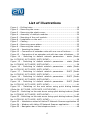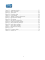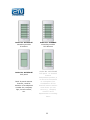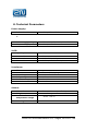
1
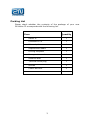
Installation Manual
1.0a
Dear customer,
Congratulations on the purchase of 2N Helios IP. This new product
was developed and manufactured with the aim to provide the
maximum user value, quality and reliability. We hope 2N Helios IP
will fully meet your satisfaction for a long time.
The manufacturer continuously improves the
product firmware. The technology used allows you
to upload to 2N Helios IP the latest version of the
firmware any time using a standard computer. The
latest version of the firmware is available at
www.2n.cz.
You
will
find
the
necessary
instructions in chapter Chyba! Nenalezen zdroj
odkazů.. of this manual. We recommend that you
use the latest version of the firmware, which
brings new functions and patches to the everimproving product.
At www.2n.cz you will also find the latest version
of the user documentation. The grey-marked text
in this manual indicates functions that will be
implemented with a newer version of the
firmware.
Before you start installing the product please
check whether your delivery is complete, using the
packing list attached, and read the instructions
specified in this manual. The manufacturer is not
liable for any damage caused by incorrect use of
the product, which is contrary to the user
documentation.
The
warranty
terms
and
conditions do not apply to product damage caused
by improper handling, improper storage or
exceeding the specified technical parameters.
The user documentation describes in detail the
installation and functions of the product and
includes also passages that are not necessary for
the basic installation.
2
Packing List
Please check whether the contents of the package of your new
2N Helios IP corresponds with the following list.
Item
Quantity
Helios IP
1
Installation CD
1
Warranty list
1
Replacement seals
1
Drilling template
1
Hexagonal wrench
1
Reserve label
1
Terminal block plug
1
Screws
2
Plastic anchors
2
3
Table of Contents
1.
Basic Properties ................................................................... 8
1.1.
Basic Properties .............................................................. 8
1.2.
Intended Use ................................................................. 8
1.3.
Optional Accessories........................................................ 9
2.
Overview of Available Product Versions...................................10
2.1.
Basic Units and Extenders ...............................................10
2.2.
Accessories for Installation ..............................................13
2.3.
Accessories for Increased Endurance ................................15
2.4.
Accessories for GSM and UMTS Network Connection ...........16
2.5.
Accessories for VoIP Network Connection ..........................16
2.6.
Electric Locks ................................................................16
2.7.
Other Accessories ..........................................................17
3.
Mechanical Installation .........................................................18
3.1.
Overview of Installation Types .........................................18
3.2.
Surface Installation ........................................................19
3.3.
Flush mouting ...............................................................23
3.4.
Installation of Increased Resistance Version.......................23
4.
Electrical Installation............................................................24
4.1.
Description of the Printed Circuit Board Connectors.............24
4.2.
Terminal Block Plug Connections ......................................26
4.3.
Configuration Connector Connection .................................28
4.4.
Display Connector ..........................................................29
5.
Connection of Extender Units ................................................31
5.1.
Maximum Count of Extender Units...................................32
5.2.
Interconnecting Modules with Cable..................................32
5.3.
Button Numbering..........................................................34
5.4.
Button Numbering – Assemblies with Info Panels: ..............35
6.
Sound Signaling and Configuration using the Keypad................36
6.1.
Tone Signaling...............................................................36
6.2.
Switching to Default Network Parameters – Static IP Address
38
4
6.3.
Switching to Default Network Parameters – Dynamic IP
Address40
6.4.
Switching on the Web Server...........................................42
7.
Configuration ......................................................................44
7.1.
Description of application Helios IP network scanner ...........45
7.2.
Login............................................................................46
7.3.
Quick Configuration for Calling.........................................47
7.4.
Language Selection ........................................................51
7.5.
Information...................................................................51
7.6.
Phone book ...................................................................53
7.7.
Scheduler .....................................................................55
7.8.
Lock.............................................................................57
7.9.
Network .......................................................................59
7.10. Date and Time...............................................................61
7.11. SIP Settings ..................................................................63
7.12. Web server ...................................................................65
7.13. Audio ...........................................................................67
7.14. Video ...........................................................................68
7.15. Audio Codecs ................................................................70
7.16. Video Codecs.................................................................72
7.17. Miscellaneous ................................................................74
7.18. Tools............................................................................76
7.19. Firmware update............................................................77
7.20. System log....................................................................79
8.
Technical Parameters ...........................................................81
5
List of illustrations
Figure 1 – Drilling holes ..................................................................19
Figure 2 – Removing the cover .........................................................20
Figure 3 – Removing the plastic cover ...............................................20
Figure 4 – Assembly of multiple modules ...........................................20
Figure 5 – Mounting of the roof module .............................................21
Figure 6 – Installation on the wall .....................................................21
Figure 7 – Cabling ..........................................................................22
Figure 8 – Removing name plates .....................................................22
Figure 9 – Removing the inserts .......................................................22
Figure 10 – Inserting the labels ........................................................22
Figure 12 – Connection of extender units with one row of buttons .........31
Figure 13 – Connection of an extender unit with two rows of buttons .....33
Figure 14 - Switching to default network parameters - static (Order
No. 9173130E, 9173130CE, 9137130CKE) .........................................38
Figure 15 - Switching to default network parameters – static (Order
No. 9173160E, 9173160CE, 9137160CKE) .........................................39
Figure 16 - Switching to default network parameters – static (Order
No. 9173110E, 9173110CE, 9137110CKE) .........................................39
Figure 17 - Switching to default network parameters - DHCP (Order
No. 9173130E, 9173130CE, 9137130CKE) .........................................40
Figure 18 - Switching to default network parameters - DHCP (Order
No. 9173160E, 9173160CE, 9137160CKE) .........................................41
Figure 19 - Switching to default network parameters - DHCP (Order
No. 9173110E, 9173110CE, 9137110CKE) .........................................41
Figure 20 – Switching on the web server using quick dialing buttons
(Order No. 9173130E, 9173130CE, 9137130CKE) ...............................42
Figure 21 - Switching on the web server using quick dialing buttons (Order
No. 9173160E, 9173160CE, 9137160CKE) .........................................42
Figure 22 - Switching on the web server using quick dialing buttons (Order
No. 9173110E, 9173110CE, 9137110CKE) .........................................43
Figure 23 – Installation wizard of Helios IP Network Scanner application 45
Figure 24 – Window with Helios IP Network Scanner application............46
Figure 25 – Navigation bar of the telephone book ...............................49
6
Figure
Figure
Figure
Figure
Figure
Figure
Figure
Figure
Figure
Figure
Figure
Figure
Figure
Figure
Figure
Figure
Figure
26
25
28
29
28
32
33
34
35
29
30
36
37
31
40
39
38
– Language selection ........................................................51
– basic information ...........................................................51
– Phone book...................................................................54
- Scheduler setup .............................................................56
- Locks settings................................................................58
– Setting up network parameters........................................60
- Date and time settings....................................................62
- SIP settings...................................................................63
- Web server confguration .................................................66
- Audio parrametres settings..............................................67
- Video parameters settings ...............................................69
- Audio codecs settings .....................................................70
- Video codecs settings .....................................................72
- Miscellaneous settings ....................................................74
- Tools ............................................................................76
- Firmware update ............................................................78
- System log....................................................................80
7
1. Basic Properties
1.1. Basic Properties
•
•
•
•
•
•
•
•
•
•
•
•
•
•
•
•
•
•
•
Works in the Ethernet network
Power supply over Ethernet - PoE
SIP communication protocol
Integrated web server for configuration
Up to 54 quick dialing buttons
Up to 999 users / user groups
Integrated scheduler with day/night/weekend modes
Modular – up to 54 buttons + keypad
Can be used as a standard VoIP telephone and a code lock
(models with keypad)
Select design, quality material – high-quality stainless steel
Flat design – can be installed without having to make a hole in the
wall
Water resistant
• Completely hermetic buttons
• Electronic part completely separated from the nametags
Switch for the electric lock – controlled directly from the VoIP
telephone
Quality white backlighting of buttons – white LEDs
DTMF according to RFC2833, in-band
High-quality acoustic characteristics
Electronic volume setting and hands-free function – without
opening the cover
Electronic adjustment of the camera brightness and contrast
Electronic adjustment of backlight
1.2. Intended Use
2N Helios IP door communicator is capable of replacing the traditional
doorbell button panel with speakerphone and the entire system of
wiring, bells and intercom installations in buildings where structured
cabling is installed. The installation is very easy, all you need to do is
8
to connect it to the other elements of the data network using a
twisted UTP cable.
By pressing any of the quick dial buttons 2N Helios IP will set up a
call to the number that had been stored in the respective memory.
The number of buttons is optional because 2N Helios IP is a kit.
Thanks to the integrated scheduler it is possible to configure the
individual buttons in such a way that the called party is always
available.
It is possible to define for each of the buttons up to three telephone
numbers, between which 2N Helios IP switches when absent.
Beside the buttons, you can also use the numeric keypad, which also
serves as a code lock. With the use of this keypad you can use the
system also as a button telephone. The keypad can be combined with
buttons and unwanted functions can be banned.
2N Helios IP provides better and broader services than normal house
intercom systems. Thanks to the integrated SIP protocol it can use all
the services of VoIP networks. Redirecting when absent (to another
office, to a voice mail or a cell phone) or switching (e.g., from the
secretary’s office to the required specific person).
In addition, 2N Helios IP includes a switch, with which you can control
the electric lock from any VoIP telephone (by entering the code using
tone dialing).
1.3. Optional Accessories
•
•
"Anti-vandal" panel
• Very strong metal cover for increased endurance against
vandalism
• The cover price includes a steel installation box for wallmounting
• It can also be purchased additionally
Additional switch
• Switching contact (relay)
• Can be switched on for unlimited time
9
2. Overview of Available Product Versions
2.1. Basic Units and Extenders
Order No.
9137110(C)E
basic unit
1 button
(C=integrated camera)
Order No.
9137130(C)E
basic unit
3 buttons
(C=integrated camera)
Order No.
9137160(C)E
basic unit
3x2 buttons
(C=integrated camera)
Order No.
9137110(C)KE
basic unit
1 button + keypad
(C=integrated camera)
Order No.
9137130(C)KE
basic unit
3 buttons + keypad
(C=integrated camera)
Order No.
9137160(C)KE
basic unit
3x2 buttons + keypad
(C=integrated camera)
10
Order No. 9135181E
extending module
8 buttons
Order No. 9135310E
Info panel
Back-lit panel without
buttons; used for
insertion of a telephone
number list, company
logo, house number,
etc.
Order No. 913582E
extending module
8x2 buttons
Order No. 9135320E
Info panel + 4 doorbell
buttons
Independent product; it
is not to be connected
to a telephone line.
Combination of four
doorbell buttons and an
area where you can
insert e.g., company
name or list of
departments or working
hours
11
Order No. 9135301E
Replacement button
nametag
Order No. 9135302E
replacement doublebutton nametag
Order No. 9135311E
Info panel – name tag
Replacement for four
nametags with one
cover. It allows you to
use a half of the
extending module
e.g., for insertion of a
telephone number list,
working hours, etc.
All units can be used also without additional accessories for surface
installation. All units can be made more robust and resistant by using
an anti-vandalism cover. To install a unit under wall coat or in
outdoor applications you need to use the accessories; see chapter
2.2.
12
2.2. Accessories for Installation
Order No.
9135331E
Surface top cover
for 1 module
dimensions
(W x H x D):
103 x 218 x 60 mm
Order No. 9135351E
Box for installation in the
wall with frame for 1
module
Dimensions:
(W x H x D):
125 x 235 x 46 mm
Hole in the wall:
110 x 220 x 50 +- 5mm
13
Order No. 9135361E
Box for installation in the wall
with roof module for 1 module
Roof module dimensions
(W x H x D):
129 x 240 x 41 mm
Hole in the wall:
110 x 220 x 50 +- 5mm
Order No.
9135332E
Surface roof module
for 2 modules
dimensions
(W x H x D):
203 x 218 x 60 mm
Order No. 9135352E
Box for installation in the
wall with frame for 2
modules
Dimensions:
(W x H x D)
225 x 235 x 46 mm
Hole in the wall:
210 x 220 x 50 +- 5mm
Order No. 9135362E
Box for installation in the wall
with roof module for 2 modules
Roof module dimensions
(W x H x D)
229 x 240 x 41 mm
Hole in the wall:
210 x 220 x 50 +- 5mm
The accessories for installation are made of stainless steel. For
outdoor applications the use of the roof module is required, unless
protection against rain is provided otherwise. The box with frame
(without roof module) allows for installation of Helios IP in indoor
applications, so that it is almost does not protrude (1 mm).
14
2.3. Accessories for Increased Endurance
Order No. 9135511E
anti-vandalism cover for
the basic module + box for
installation in the wall
vandalism-resistant *)
Order No.
9135511KE
anti-vandalism cover for 1
basic module with keypad
+ box for installation in the
wall, vandalism-resistant *)
Order No. 9135515E
anti-vandalism cover for 1
extending module + box
for installation in the wall,
vandalism-resistant *)
*) Warning! Box order No. 9135351E cannot be used!! For installation
of vandalism-resistant covers you need to use a dedicated box!
These covers are used to make the basic unit or assemblies with up
to 11 buttons more resistant. Greater assemblies can be provided
upon individual request. More resistant version is always to be
installed under the wall coat. No roof module is used for this version;
outdoor use is possible without the roof module.
15
2.4. Accessories for GSM and UMTS Network Connection
Order No. 505004E
2N VoiceBlue Lite
Order No. 505214E
2N VoiceBlue
Enterprise
Order No. 505612E
2N UMTS Office Route
2.5. Accessories for VoIP Network Connection
Order No. 91378100
PoE injector
Order No. 91378300
Grandstream VoIP
telephone
Order No. 91378350
Grandstream VoIP
video telephone
Order No. 932080E
BEFO 1221
with momentum pin
Order No. 932090E
BEFO 1211MB
with mechanical
blocking
2.6. Electric Locks
Order No. 932070E
BEFO 1211 12V / 600
mA
16
2.7. Other Accessories
Order No.
9137310E
Additional switch
Order No.
91341481E,
91341481AU,
91341481GB,
91341481US
adaptor 12 V / 2 A
Enables control
of a second
appliance,
connecting and
disconnecting
contact option,
connecting for
unlimited time,
max. 48 V / 2A
Stabilized power source
needs to be used if power
supply over Ethernet (PoE)
is not used
17
Order No. 932928 12V
transformer
3. Mechanical Installation
3.1. Overview of Installation Types
Overview of the installation types and the list of the required
components is provided in the table below.
Overview of installation types
What you need for the installation
Indoor,
on
surface
- only 2N Helios IP
Indoor,
under
wall
coat
2N Helios IP
box with frame for 1 module
Order No. 9135351E, or
box with frame for 2 modules
Order No. 9135352E
Outdoor,
on
surface
2N Helios IP
Surface roof module for 1 module
Order No. 9135331E, or
Surface roof module for 2 modules
Order No. 9135332E
Outdoor,
under
wall
coat
2N Helios IP
Box for installation in the wall with roof
module for 1 module
Order No. 9135361E or
Box for installation in the wall with roof
module for 2 modules
Order No. 9135362E
With
increase
d
resistan
ce
2N Helios IP
vandalism-resistant cover with box,
version according to the assembly
18
Indoor application shall mean:
Indoor areas with low relative air humidity (e.g.,
hallways, offices and other heated rooms)
Indoor areas where humidity condensates on
walls, but does not ever flow down the walls
(e.g., porches, storage areas, industrial areas)
Outdoor areas, if protection against rain and
water flowing down the wall is provided (e.g.,
sheds, passages)
Outdoor application shall mean:
Environment where the product is exposed to rain or
where water may flow down the walls (e.g., fence,
outer wall of a building).
The warranty shall not apply to product failures
and defects caused improper installation (contrary
to these instructions). The manufacturer is also
not liable for damages caused by theft within an
area that is accessible after the attached electric
lock is switched. The product is not designed as
burglar protection – only in combination with a
standard lock, which has the security function.
3.2. Surface Installation
1) Drill holes according to
the template included in
the Helios IP supply.
Insert
the
included
plastic anchors in the
holes in the wall.
2) Use a hexagonal wrench,
which is included in the
supply, remove the metal
cover of Helios IP. In the
Figure 1 – Drilling holes
19
3)
4)
5)
6)
7)
lower part of the metal cover remove the screw and fold out the
cover as shown on Figure 2.
Use a screwdriver for cross-recess screws to remove the plastic
cover and remove the cover.
In
assemblies
with
multiple modules connect
the boxes according to
Figure
4.
The
basic
module on the left, the
extending modules on the
right.
The
connecting
cable is to be connected
Figure 2 – Removing the cover
later!
Install plugs on unused
side holes, as shown on
Figure 4.
If you are installing a roof
module, put it against the
wall now.
Fix Helios IP on the wall
with screws, as shown on
Figure 6. The incoming
Figure 3 – Removing the plastic cover
cables (Ethernet, lock,
power) are to be led
through one of the holes
to the basic module box.
Figure 4 – Assembly of multiple
modules
20
WARNING!!
Mount the Helios IP door communicator always on
the flat surface. Pay attention to avoid mechanical
overload on the bottom part of the cover. The
incorrect installation on the uneven surface may
lead to deformation of the cover and thereby to
incorrect functions of product.
8) If you are installing a roof module, apply now silicon paste on the
top and side edges touching the wall, as shown on Figure 5.
9) Connect the cables as described in chapter 4. Make sure that the
cables are not squeezed when installing the plastic cover. Correct
installation of the cables is shown on Figure 7
10) After having mounted the
unit on the wall and after
having
connected
all
cables
re-attach
the
plastic cover using crossrecessed screws.
11) Take out the name plates
from the plastic cover, as
shown on Figure 8. Use
for
example
a
Figure 5 – Mounting of the roof
screwdriver.
module
12) Remove the inserts from
the nametags.
13) Insert the labels printed
on the foil.
14) Insert the inserts back
into the nametags.
15) Put the name plates back
to the recess, snap all the
way. The name labels
hold the matt foil inserted
Figure 6 – Installation on the wall
underneath.
21
16) Check whether silicon seal is inserted in the top groove of the
plastic cover. Replacement seal is included.
17) Close the metal cover and fix it with screws.
Figure 7 – Cabling
Figure 9
inserts
–
Figure 8 – Removing name
plates
Removing
the
Figure 10 – Inserting the labels
Principles to be followed during outdoor installation:
•
•
•
Always connect button backlighting – it is used
for heating
The joint between the roof module and the wall
must be filled with waterproof c to prevent
water leaking into the box (see figure 5).
Water must not leak in on the cables or around
them.
22
Material and label print
Each Helios IP package includes a sheet of
transparent foil, which can be used for printing in
a laser printer. Cut the printed foil in tje pieces,
and insert the labels in the name plates. Do not
use paper – water may leak in and the paper may
be damaged.
The red arrows are printed on the name label
itself. Make sure the text and the arrow do not
overlap. We recommend printing on the
transparency using a template (MS Word), which
is available at www.2n.cz .
Horizontally
divided
Whole button
Name 01
Name 02
Name 03
Name 01
Name 04
Name 02
Name 05
Name 03
Name 06
3.3. Flush mouting
Use the installation instructions included in the flush mouting box
delivery.
3.4. Installation of Increased Resistance Version
Use the installation instructions included in the anti-vandal box
delivery.
23
4. Electrical Installation
Helios IP is designed for connection in Ethernet computer network
(10/100BASE-T) using a twisted UTP cable. Use at least UTP CAT 5e
cable for the connection.
Helios IP receives power through the PoE (Power over Ethernet)
technology. No additional cabling is therefore necessary. If your
Ethernet is not equipped with the PoE technology it is possible to use
a PoE injector, order No. 91378100. As an alternative power supply
you can use a power adaptor, Order No. 91341481E. Helios IP is
configured over an integrated web server, which can be controlled
from any web browser, e.g., Mozilla Firefox.
4.1. Description of the Printed Circuit Board Connectors
On Figure 11 you can see the location of the printed circuit board
(PCB) connectors. Connectors, to which the accessories can be
connected, and connectors that serve for configuring Helios IP are
indicated on the board. UTP cable for the Ethernet connection is to be
connected to the terminal box as shown in Tab. 1. The terminal box
can be removed from the PCB. Connection of the individual
connectors will be described in the following chapters.
24
Power
adaptor
Order No.
91341481E
-
El. lock
+
Order No.
932070E
932080E
932090E
+
Terminal block plug
12V / 2A DC
+
+
Configuration connector
10
9
8
7
6
5
4
3
2
Speaker
connector
Display
connector
Camera
connector
1
Card reader
connector
Additional lock
connector
Microphone
connector
Connector for
extending modules
Figure 11 – description of Helios IP connectors
25
4.2. Terminal Block Plug Connections
Terminal block plug includes several terminals whose function is
distinguished by color. Terminals 1-6 serve for connecting Helios IP to
the Ethernet. Terminals 7-8 are designed for connecting the electric
lock and terminals 9-10 for connecting external power supply
12V / 2A DC, if power supply using the Power over Ethernet
technology is not provided.
1) Terminal block plug is included in the package. For adjusting of
already installed Helios IP unplug the Helios IP form the power
supply. After that remove the terminal block plug by pulling it from
the printed circuit board.
2) Insert the individual wires under the terminals.
3) Tighten the terminals using a flat screwdriver to prevent the
cables from falling out.
4) Replace the terminal block plug back to the printed circuit board.
Pay attention to correct installation of the cables
on the bottom part of the cover Helios IP. Make
sure that the cables are not squeezed. Correct
installation of the cables is shown on Figure 7.
Ethernet connection
Connections and meaning of the individual wires are specified in the
table below. Join wires 4 (blue) and 5 (white-blue) from the UTP
cable and attach under terminal 5 on Helios IP. In the same way, join
wires 7 and 8 and place under terminal 6 of Helios IP.
26
RJ-45
8
Helios IP
1
Pin No.
Marking
Color
Terminal No.
1
Tx+
1
2
Tx-
2
3
Rx+
3
4
PoE -
5
5
PoE -
5
6
Rx-
4
7
PoE +
6
8
PoE +
6
6
5
4
3
2
1
Tab. 1 – terminal block plug connections
Connecting the electric lock
The electric lock can be connected to terminals 7 and 8 of the
terminal box.
El. lock
Helios IP
Marking
Color
+
Terminal No.
7
8
7
-
8
Order No.
932070E
932080E
932090E
Tab. 2 - terminal block plug connection for the el. lock
Terminals 7 and 8 are connected on the board of Helios IP to the
relay, whose terminals can act as connecting as well as disconnecting
terminals. Configuration is performed through the configuration
connector, which is described in chapter 4.3. On the configuration
connector you can set whether the electric lock will be powered from
an external or internal power source.
27
Connecting external power supply
If the Ethernet is not equipped with the PoE technology it is possible
to use two alternative ways to supply power to Helios IP.
1) Using PoE injector, order No. 91378100; Helios IP is then powered
through an Ethernet cable as shown above.
2) Using a power adaptor, order No. 91341481E.
External power supply from the power adaptor can be connected to
terminals 9 and 10.
El. lock
Helios IP
Marking
Color
Terminal No.
+
9
-
10
10
9
Order No.
91341481E
Tab. 3 – terminal block plug connection for power adaptor
4.3. Configuration Connector Connection
The configuration connector is located in the upper part of the printed
circuit board. With the configuration jumpers you can set whether the
lock control relay should have connecting or disconnecting function
and whether the electric lock will be powered internally or externally.
28
Lock power supply
Internal
External
Relay
Disconnecting
Configuration connector
Connecting
Connection of jumpers
1234567
1234567
1234567
1234567
Tab. 4 – Connection of jumpers of the configuration connector
4.4. Display Connector
The display connector includes pins for switching-on and switching-off
of the name labels backlighting and also pins whose interconnection
will result in switching Helios IP to the default settings. The remaining
pins are designed for display connection.
29
Nametag
backlighting
Default settings
Jumpers of the display connector
Tab. 5 – Configuration jumpers on the display connector
30
5. Connection of Extender Units
The benefit of Helios IP is easy installation of extending button units.
It cannot be easier – they can be connected with a single cable (it is
included with every extender delivery) – in chain pattern (each
additional unit is connected with the previous one). Each extender
unit has two connectors, input connector (for connection toward the
basic unit of Helios IP) and output connector (for connection of
another, more remote unit). For correct function and sequence of
buttons it is necessary to comply with the correct orientation of the
units and avoid interchanging these connectors!
This connector is designed
for
the
connection
of
additional extender unit.
Figure 12 – Connection of extender units with one row of buttons
31
5.1. Maximum Count of Extender Units
Order No. 9135181
(1x8 buttons)
6
5
4
3
2
1
0
Order No. 9135182
(2x8 buttons)
0
0
1
1
2
2
3
Tab. 6 – Optional extension of Helios IP by extending modules
The above table shows that units with whole buttons and double
buttons can be combined.
5.2. Interconnecting Modules with Cable
•
•
•
The cable is supplied with every extender unit delivery. Both ends
are the same. Connection is 1:1. Connectors cannot be inserted
shifted or reversed because they are equipped with a so-called
key.
The basic unit is to be on the left always. Units are to be
connected in “chain pattern”, i.e., each is connected with its
neighbor.
The cable can be driven through the connecting opening between
boxes after connecting (see chapter 3).
32
This connector is designed
for connection
Figure 13 – Connection of an extender unit with two rows of buttons
Warning!
The extending modules must be connected
mutually and also with the basic unit by means of
a connection – formed piece, which is supplied
with the extending module!!!
33
5.3. Button Numbering
1
Applies
also to
assemblies
with
keypad.
7
15
23
8
16
24
9
17
25
10
18
26
11
19
27
12
20
28
13
21
29
14
22
30
It is possible to continue to 54
Button numbering – Helios IP with one button with an
assembly with whole buttons
Applies
also to
assemblies
with
keypad.
7
15
23
1
8
16
24
2
9
17
25
3
10
18
26
11
19
27
12
20
28
13
21
29
14
22
30
34
It is possible to continue to 54
Button numbering – assemblies with whole buttons
7
15 23
31 39
47
1
4
8
16 24
32 40
48
2
5
9
17 25
33 41
49
3
6
10
18 26
34 42
50
11
19 27
35 43
51
12
20 28
36 44
52
13
21 29
37 45
53
14
22 30
38 46
54
Applies
also to
assemblies
with
keypad.
Warning:
For the time being, anti-vandalism panels are
available only for assemblies with whole buttons
and with one extending module.
5.4. Button Numbering – Assemblies with Info Panels:
Numbering will not change (buttons on the sides of the info panel will
remain functional) by installing a name labels of the info panel, Order
No. 9135311E, in one of the extending units. Connecting the info
panel module, Order No. 9135310E, will result in omission of eight
numbers.
35
L It is possible to continue to 54
Button numbering – assemblies with double buttons
6. Sound Signaling and Configuration using the Keypad
Helios IP allows configuration and setup using the keypad and quick
dialing buttons. For checking purposes Helios IP signals status
changes. There are different types of signals for each type of status
change. List of the individual signals is provided in Tab. 7
6.1. Tone Signaling
Tones
Meaning
User activated – after entering the user activation
code. The activation code is used to get an overview
whether a user is active and whether his/her VoIP
telephone should ring, or whether the call should
therefore be routed directly to another telephone
number. Setup of the activation code is described in
chapter 7.6.
User deactivated – after entering the user
deactivation code. The deactivation code is used to
get an overview whether a user is inactive and
whether the call should therefore be routed directly
to another telephone number. Setup of the
deactivation code is described in chapter 7.6.
Scheduler activated – used for activating the
scheduler. It can be used, for example, to switch on
the ringing of an entire group of users at telephone
numbers directly in the office. Setup of the
activation code is described in chapter 7.7
Scheduler deactivated – used for deactivating the
scheduler. It can be used, for example, to switch off
ringing at telephone numbers in the office and
routing, if applicable, to one telephone number,
e.g., at the reception or a cell phone. Setup of the
deactivation code is described in chapter 7.7
Signaling of confirmation of call prolongation – Due
to protection blocking, Helios IP has a set maximum
36
call duration, see chapter 7.17
Internal application launched – after turning on the
power or restarting of Helios IP, the internal
application of Helios IP is launched. Successful
launch of the internal application is signaled by this
tone combination.
Connected to internal network, IP address received
– After the launch of the internal application Helios
IP signs in the internal network. Successful sign-up
to VoIP network is signaled by this tone
combination.
Disconnected from the internal network, IP address
lost – in the event that the UTP cable is
disconnected from Helios IP, this status is signaled
by this tone combination.
Invalid telephone number or invalid code for
unlocking – Helios IP allows you to dial a branch
telephone number or enter the code to open the
door using the keypad. If this code is invalid this
status is signaled by this tone combination.
Switching to default network parameters – after
launching of internal application a time limit of 30 is
set for entering the code for switching to default
network parameters. Switching to default network
parameters is described in chapter 6.2 a 6.3.
Signaling of approaching end of call – Helios IP
allows you to set a time limit after which a call is
terminated. The call can be prolonged by pressing a
key from the VoIP telephone. The time limit is set
due to protection against call blocking.
Connected call when calling from VoIP telephone at
Helios IP – When calling from VoIP telephone at
Helios IP a short tone is played to signal the call
connecting.
Tab. 7 – List of tone signals
37
6.2. Switching to Default Network Parameters – Static IP
Address
Switching to default network parameters with static IP address can be
done in two ways. Either through a web interface, as described in
chapter 7 or by pressing a combination of quick dialing buttons.
If required, it is possible to switch on default settings with static IP
address using quick dialing buttons of the basic module of Helios IP.
Upon switching, the web server is automatically switched on.
Switching on default network parameters is possible by pressing a
combination of buttons described on Figure 14 to Figure 16. The
combination of buttons needs to be entered within 30 seconds after
launching of internal application. Maximum delay between the
buttons is 2 s.
1
- 1) 3x
2
- 2) 2x
3
- 3) 1x
Applies also
to
assemblies
with
keypad.
Figure 14 - Switching to default network parameters - static (Order
No. 9173130E, 9173130CE, 9137130CKE)
38
1
4
- 1) 3x
2
5
- 2) 2x
3
6
- 3) 1x
Applies also
to
assemblies
with
keypad.
Figure 15 - Switching to default network parameters – static (Order
No. 9173160E, 9173160CE, 9137160CKE)
1
-1) 15x
Applies also
to
assemblies
with
keypad.
Figure 16 - Switching to default network parameters – static (Order
No. 9173110E, 9173110CE, 9137110CKE)
For Helios IP with one button (Order No. 9137110E, 9137110CE and
9137110CKE), pressing key 1 15 times within 30 seconds after
launching of internal application will result in turning on of the web
server and switching the network parameters from DHCP to default
static IP address and vice versa.
39
6.3. Switching to Default Network Parameters – Dynamic
IP Address
Switching to default network parameters with dynamic IP address can
be done in two ways. Either through a web interface, as described in
chapter 7 or by pressing a combination of quick dialing buttons.
If required, it is possible to switch on default settings with dynamic IP
address using quick dialing buttons of the basic module of Helios IP.
Upon switching, the web server is automatically switched on.
Switching on default network parameters is possible by pressing a
combination of buttons described on Figure 17 to Figure 19. The
combination of buttons needs to be entered within 30 seconds after
launching of internal application. Maximum delay between the
buttons is 2 s.
1
- 2) 2x
2
- 1) 1x
3
- 4) 1x
-3) 2x
Applies also
to
assemblies
with
keypad.
Figure 17 - Switching to default network parameters - DHCP (Order
No. 9173130E, 9173130CE, 9137130CKE)
40
1
4
- 2) 2x
2
5
- 1) 1x
3
6
- 4) 1x
-3) 2x
Applies also
to
assemblies
with
keypad.
Figure 18 - Switching to default network parameters - DHCP (Order
No. 9173160E, 9173160CE, 9137160CKE)
1
-1) 15x
Applies also
to
assemblies
with
keypad.
Figure 19 - Switching to default network parameters - DHCP (Order
No. 9173110E, 9173110CE, 9137110CKE)
For Helios IP with one button (Order No. 9137110E, 9137110CE and
9137110CKE), pressing key 1 15 times within 30 seconds after
launching of internal application will result in turning on of the web
server and switching the network parameters from default static IP
address to dynamic address and vice versa.
41
6.4. Switching on the Web Server
If the web server was switched off from the web interface it is
possible to switch it back on using quick dialing buttons of the Helios
IP basic module. Web server can be switched on by pressing a
combination of buttons as described on Figure 20 to Figure 22. The
combination of buttons needs to be entered within 30 seconds
launching of internal application. Maximum delay between the
buttons is 2 s.
1
- 2) 2x
2
- 3) 2x
3
- 1) 1x -4) 1x
Applies also
to
assemblies
with
keypad.
Figure 20 – Switching on the web server using quick dialing buttons (Order
No. 9173130E, 9173130CE, 9137130CKE)
1
4
- 2) 2x
2
5
- 3) 2x
3
6
- 1) 1x -4) 1x
Applies also
to
assemblies
with
keypad.
Figure 21 - Switching on the web server using quick dialing buttons (Order
No. 9173160E, 9173160CE, 9137160CKE)
42
1
-1) 15x
Applies also
to
assemblies
with
keypad.
Figure 22 - Switching on the web server using quick dialing buttons (Order
No. 9173110E, 9173110CE, 9137110CKE)
For Helios IP with one button (Order No. 9137110E, 9137110CE and
9137110CKE), pressing key 1 15 times within 30 seconds after
launching of internal application will result in turning on of the web
server and switching the network parameters from default static IP
address to dynamic address and vice versa.
43
7. Configuration
Helios IP is configured through an integrated web server. Connect
Helios IP to the IP network. Make sure that Helios IP is powered.
Obtaining the IP address from the DHCP server
In default settings, Helios IP has receiving of IP address from
the DHCP server turned on. After start, Helios IP will automatically
receive IP address from the DHCP server. If you do not have access
to the DHCP server you can find the IP address received with the
HeliosIPNetScanner program, which is included on the installation CD.
If Helios IP is switched to the static IP address mode switch it to the
mode for obtaining address from the DHCP server as follows:
1) Switch on the power of Helios IP
2) Wait until Helios IP ends the booting process. The end is signaled
by a sequence of tones:
3) Within 30 seconds press buttons in the order described in chapter
6.3.
4) Switching to the mode for obtaining address from the DHCP server
is signaled by a sequence of tones:
Manual setup of the IP address
If DHCP server is not available it is possible to set up a default static
IP address on Helios IP. Proceed as follows.
1) Switch on the power of Helios IP
2) Wait until Helios IP ends the booting process. The end is signaled
by a sequence of tones:
3) Within 30 seconds press buttons in the order described in chapter
6.2.
4) Switching to the default static IP address mode is signaled by a
sequence of tones:
44
5) Helios IP now has the following network parameters set
IP address:
192.168.1.100
Network mask:
255.255.255.0
Default gateway:
192.168.1.1
7.1. Description of application Helios IP network scanner
Purpose of this application is to find the dynamic IP address of Helios
IP in the local IP network. The application is included on the
installation CD, which is part of the Helios IP package. For installation
is required to have installed Microsoft .NET Framework.
1) Run installer of HeliosIP Toolkit
2) Installation wizard will guide you through installation
Figure 23 – Installation wizard of Helios IP Network Scanner application
3) After installing the application Helios IP Network Scanner, run the
application from Start menu of Microsoft Windows operating
system.
4) The application starts automatically searching on local network for
all Helios IP communicators, which have turned on retrieving IP
address from DHCP server. These communicators will be displayed
in the table.
45
Figure 24 – Window with Helios IP Network Scanner application
5) Select from the list the respective communicator Helios IP, which
you want to configure. Click on it with the right mouse button and
select Browse to open a window with a web browser, whereby is
possible to login to Helios IP and start configuring as described in
chapter 7.2.
7.2. Login
In web browser enter the IP address of Helios IP. After you enter this
address a login screen will be displayed. The default login username
and password are:
Username:
admin
Password:
admin
If the login screen does not appear an incorrect IP address was
entered in the web browser or the configuration web server of
Helios IP was turned off. If you are not sure of IP address of Helios
IP, use the application Helios IP Network Scanner, which is described
in chapter 7.1. Switching on of the configuration web server is
described in chapter 6.4 Please check the IP address entered, or, if
applicable, check the way the IP address was obtained as described
at the beginning of chapter 6.
46
7.3. Quick Configuration for Calling
This chapter describes the most common and fastest configuration.
The following paragraphs describe the individual parameters of the
configuration in more detail.
Language selection
Before starting configuration, select the language of configuration
web server. Use the tab menu in the upper right corner to select
language.
Network settings
If you have not set obtaining IP address from DHCP server you need
to change the default IP address of Helios IP. You can set the IP
address in “Advanced settings -> Network”, as shown in 7.9.
Static parameter settings
Static IP address
Set the static IP address that Helios IP should have set.
Network mask
Set the network mask.
For Windows users: You will find out the network mask if you enter
ipconfig –all in the command line.
Default gateway
Enter the default network gateway.
For Windows users: You will find out the default gateway if you enter
ipconfig –all in the command line.
Primary DNS
Set the IP address of the primary Domain Name Server used in your
computer network.
For Windows users: You will find out the default gateway if you enter
ipconfig –all in the command line.
Secondary DNS
Set the IP address of the secondary Domain Name Server used in
your computer network.
For Windows users: You will find out the default gateway if you enter
ipconfig –all in the command line.
47
SIP parameter settings
In order to set up calls from Helios IP it is necessary set up the
parameters of your VoIP network. Setup is made in “Advanced
settings -> SIP settings”
Display name
Fill out the name that will be displayed on the called party’s IP
telephone display. This information will be entered in the message
INVITE in the “Contact – SIP display info” field. This name will be
displayed in the right upper corner and Helios IP will be identified
with this name in the Helios IP Network Scanner application.
User ID
Identification, with which Helios IP will present itself. When calling
Helios IP this number is dialed from an IP telephone. This number is
included in the message INVITE in the “Contact – SIP contact
address” field as “user_id@user_domain:port”. For calling Helios IP
the User ID is included in the message INVITE in the “From” field and
specifies the logical address of the caller, in this case Helios IP. For
calls routed to Helios IP the User ID is included in the “To” field and
specifies the logical address of the called party, in this case Helios IP.
Domain
Enter the domain name of SIP proxy, to which Helios IP will be
registered.
Use Auth. ID
Sets whether Helios IP should register to SIP proxy using
authentication information or only with User ID.
Auth ID
Authentication name, with which Helios IP registers to SIP proxy.
Password
Password for authentication in the registration of Helios IP with SIP
proxy.
Proxy address
IP address of SIP proxy, to which Helios IP should be registered
Proxy port
Communication port of SIP signaling to SIP proxy, to which Helios IP
registers.
48
Register Helios IP
Sets whether Helios IP should register with the SIP proxy. The
parameter is dependent on the settings of the SIP proxy server,
whether the SIP proxy server requires the registration or not.
Registration expires
Sets the time interval which Helios IP should set in SIP proxy for
renewal of registration.
Phone book settings
Phone book is used for configuration of quick dialing buttons.
Configuration of the phone book is done in “Basic settings
-> Phone book”. Phone book includes 999 positions. First 54 positions
are same as quick dialing buttons of Helios IP including all extenders
(see chapter 5). To select a quick dialing button use the upper bar
with the numbers of the individual buttons. Numbering of the
individual buttons on Helios IP including the extending modules is
described in chapter 5.3. You can move between the individual
buttons with the arrow, or by quick dialing, which is located in the
upper right corner, as indicated in Figure 25.
Figure 25 – Navigation bar of the telephone book
Position enabled
Sets whether the position in phone book is active or not. Dialing
position is possible with the respective quick dialing button (for
49
position 1 to 54) or with entering position in phone book by keyboard
of Helios IP.
Position name
Used to fill in the name of the person who will be called when the
button is pressed.
Phone numbers
Used to set up to three phone numbers that will be called one after
another when the button is pressed.
Number x:
Enter the phone number of the station to which the call is to be
routed. If the call is not accepted by the station with the phone
number specified under Number 1 it will be redirected automatically
to the phone number specified under Number 2, and so on. Setup of
the time for switching to the next phone number is described in
chapter 7.17.
Scheduler
Used for setting the scheduler, person hidden under the specific
telephone number. It does not have to be set for quick configuration
of calling.
The remaining parameters need not be set for the easiest
configuration. For detailed configuration, the remaining parameters
are described in the following chapters.
Setup of Lock 1
The code for lock 1 switching (terminal block plug – terminals 7 and 8
see chapter 4.2) can be set in the following menu: “Basic Settings ->
Lock 1”
Lock Setting
Sets whether the lock is to be active and for how long it should be
connected when the correct code for opening has been entered.
Lock Codes
In the individual fields write the codes, with which the Helios IP lock
can be opened. If the codes are identical with other codes already
entered in Helios IP the following mark will appear with the respective
codes: .
50
Helios IP is now ready to make calls.
7.4. Language Selection
You can select the language using the tab menu in the upper right
corner, as displayed in Figure 26.
Figure 26 – Language selection
7.5. Information
In this section it is possible to find the basic statistics on the
respective Helios IP.
Figure 27 – basic information
51
Product name – name of the product Helios IP. The name can be
changed through settings described in chapter Chyba! Nenalezen
zdroj odkazů..
Software version – version of the firmware in Helios IP. Firmware
update is described in chapter 7.19.
Bootloader version – version of the main application. It can be
changed only by servicing centre.
Hardware version – Helios IP hardware version
Serial number – product serial number
MAC address – Ethernet interface address
Up time – time, over which Helios IP is on
Registration status – Helios IP k SIP proxy registration status
- in progress – registration of Helios IP to SIP proxy in
progress
- registered – Helios IP is registered to SIP proxy
- not registered – Helios IP is not registered to SIP
proxy
Registration at – IP address or domain name of SIP proxy, at which
Helios IP is registered
Registration time – registration date and time
Call state – current call status
- Inactive – system inactive
- Call setup – call being set up
- Ringing – ringing at VoIP phone
- Incoming – setup call from VoIP phone to Helios IP
- Outgoing – Call from Helios IP to VoIP phone
Opponent – displays the called phone number from Helios IP
Call duration – duration of the current call
Audio codec – displays the audio codec used for the current call
Video codec - displays the video codec used for the current call
DHCP status – displays whether the function of obtaining IP address
from DHCP server is on.
IP address – set IP address
Net mask – set subnet mask
Default gateway – set default gateway of the network
Primary DNS – set primary Domain Name Server
52
Secondary DNS – set secondary Domain Name Server
Ethernet frames transmitted – number of Ethernet frames
transmitted
Ethernet frames received – number of Ethernet frames received
Ethernet frames dropped – number of Ethernet frames dropped
due to damage
UDP packet transmitted – number of UDP packets transmitted
UDP packet received – number of UDP packets received
UDP packet dropped – number of UDP packets dropped due to
damage
TCP packet transmitted – number of TCP packets transmitted
TCP packet received – number of TCP packets received
TCP packet dropped – number of TCP packets dropped due to
damage
7.6. Phone book
Phone book can be set up in the tabs: “Basic settings -> Phone
book”. In the phone book you can set up to three phone numbers for
each position.
53
Figure 28 – Phone book
First 54 positions are same as quick dialing buttons. Numbering of
the individual buttons on Helios IP including the extending modules is
described in chapter 5.3. You can move between the individual
buttons with the arrow, or by quick dialing, which is located in the
upper right corner, as indicated in.
General settings
Position enabled
Sets whether the respective quick dialing button is active or not.
Position name
Used to fill in the name of the person who will be called when the
button is pressed.
54
Phone numbers
Used to set up to three phone numbers that will be called one after
another when the button is pressed.
Number x:
Enter the phone number of the station to which the call is to be
routed. If the call is not accepted by the station with the phone
number specified under Number 1 it will be redirected automatically
to the phone number specified under Number 2 and so on.
Time profile
Used for selecting the scheduler for the person hidden under the
specific phone number. The setup of scheduler is described in chapter
7.7.
Substitute if inaccessible
Enter the person whom will be the call transferred if the person is not
reched.
User activation & deactivation
Sets user activation and deactivation DTMF codes. The user can
activate or deactivate him/herself using the Helios IP keypad.
Activation and deactivation in combination with the scheduler settings
determines whether a call will be set up to the respective the phone
number.
User door lock codes
In the individual fields write the codes, with which the Helios IP lock
can be activated. If the codes are identical with other codes already
entered in Helios IP the following mark will appear with the respective
codes: .
7.7. Scheduler
Scheduler helps to plan calling to the individual users. In the event
that a user is not present it is not necessary for Helios IP to set up a
call to his or her telephone number but it can automatically call other
telephone numbers in the book or the successor number. Total
number of profiles is 20, and they can be mutually shared among the
55
individual users. The condition of profile validity is possible in two
ways. Time condition, by setting Time schedule, or manually by
setting the profile activation and deactivation codes. If it is necessary
to use both functions at the same time both conditions must be met
at the same time.
Figure 29 - Scheduler setup
General settings
Profile name
Name of the scheduler profile for better orientation
Profile schedule
Sets presence or absence of the user during the week.
Profile activation & deactivation
56
Used to set up DTMF codes for activation and deactivation of the
respective scheduler.
User active if…
Sets how the respective scheduler should be used in combination with
the user settings in the phone book. Whether the phone number will
be called or not shall be governed by the claim logic rules.
Profile active only (independent)
If this is selected the calls to the specific phone number is governed
by this scheduler only. It is not affected by user activation or
deactivation.
Profile & user active
The phone number complemented with this scheduler is only called at
the time specified according to the scheduler validity (see above) and
when the respective user is active. User activation and deactivation
can be changed by DTMF codes.
Profile & user not active
The phone number complemented with this scheduler is only called at
the time specified according to the scheduler validity (see above) and
when the respective user is not active. User activation and
deactivation can be changed by DTMF codes.
Profile or user active
The phone number complemented with this scheduler is only called at
the time specified according to the scheduler validity (see above) or
when the respective user is in the active status. It can be used if the
user is present at the respective telephone number at the time when
he/she usually is not present
Profile or user not active
The telephone number complemented with this scheduler is only
called at the time specified according to the scheduler validity (see
above) or when the respective user is in the inactive status. It can be
used, for example, when routing calls to the user’s cell phone.
7.8. Lock
This menu sets whether locks can be activated and with which DTMF
codes from the keypad of Helios IP they can be activated.
57
Figure 30 - Locks settings
Lock settings
Lock enabled
Sets whether lock control should be active or not.
Switch-on-duration
Sets the duration of the lock switch-on if the correct DTMF code has
been entered on the Helios IP or VoIP phone keypad. For DTMF
receiving format see chapter 7.15.
Lock synchronization (for Lock 2 only)
Sets whether the lock switch-on is controlled by switch-on of the Lock
1. If it is selected “Yes”, then is necessary to set the second lock
delay. This parameter is suitable to set, if the Helios IP is equipped by
the additional switch (order number 9137310E)
Second lock delay (for Lock 2 only)
58
Sets delay in seconds for switch-on for Lock 2 after the end of switchon of Lock 1. For activation of delay switch-on, it is necessary to
enable this function by setting the “Lock synchronization” on value
“Yes”.
Lock codes
List of the individual DTMF codes and codes entered by Helios IP
keyboard that activate the lock switching. These codes are meant for
global use. It means that each user can activate the lock with these
codes. In addition to these ten codes, each user owns a code for lock
opening.
7.9. Network
This menu is used to set the network parameters of Helios IP. In
default settings, obtaining IP address from DHCP server is switched
on. To find the IP address of Helios IP use Helios IP Network Scanner
program included on the CD. With it you can log in Helios IP (see
chapter 7.1) and edit network parameters of Helios IP. If you do not
want to obtain IP address from DHCP server you must switch off this
function and change the default IP address of Helios IP. Static IP
address is possible to set after startup of Helios IP by pressing a
combination of quick dialing buttons or through a web interface as is
described in this chapter.
59
Figure 31 – Setting up network parameters
DHCP settings
DHCP client enabled
Switches on the function of obtaining IP address from DHCP server
Static settings
Static IP address
Setup of static IP address, which Helios IP should have set if the
function of obtaining IP address from DHCP server is not switched on.
Network mask
Network mask setup. For Windows users: Find out the network mask
by entering ipconfig –all in the command line.
Default gateway
Default network gateway setup.
60
For Windows users: Find out the default gateway by entering:
ipconfig –all in the command line.
Primary DNS
Setup of IP address of the primary Domain Name Server used in your
network.
For Windows users: Find out the default gateway by entering:
ipconfig –all in the command line.
Secondary DNS
Setup of IP address of the secondary Domain Name Server used in
your network.
For Windows users: Find out the default gateway by entering:
ipconfig –all in the command line.
7.10. Date and Time
This menu allows you to set the date and time of Helios IP. Time
setup is important for correct function of schedulers and accurate
diagnostic reports. Time can be set in three ways: manually, by
synchronization with PC, from which Helios IP is configured, or
through the NTP protocol.
61
Figure 32 - Date and time settings
Time zone
Time zone
Sets the time offset at the place of installation relative to
GMT - Greenwich Mean Time. This settings is intended to switch a
daylight saving time in spring and autumn.
TZ rule
In case, the location is not situated in the selected time zone above.
Time synchronization
Use NTP server
Sets whether Helios IP should synchronize from NTP server (Network
Time Protocol server).
NTP server address
Sets the http address of the NTP server for synchronization of Helios
IP.
62
Local date & time
Date and time setting in the following format: yyyy-mm-dd
hh:mm:ss (year-month-day hour:minute:second). It is used in the
case synchronization using NTP is not switched on.
The icon
located next to this field is used for synchronizing the
current time with PC, from which Helios IP is configured.
7.11. SIP Settings
In order to set up calls from Helios IP it is necessary to set up the
parameters of your VoIP network. Setup is done in the following
menu: “Advanced settings -> SIP settings”
Figure 33 - SIP settings
63
User settings
Display name
Name that will be displayed on the called party’s IP phone display.
This information will be entered in the message INVITE in the
“Contact – SIP display info” field.
User ID
Identification, with which Helios IP will present itself. When calling
Helios IP this number is dialed from an IP phone. This number is
included in the message INVITE in the “Contact – SIP contact
address” field as “user_id@user_domain:port”. For calling Helios IP
the User ID is included in the message INVITE in the “From” field and
specifies the logical address of the caller, in this case 111. For calls
routed to Helios IP the User ID is included in the “To” field and
specifies the logical address of the called party, in this case 111.
Domain
Enter the domain name of SIP proxy, to which Helios IP will be
registered. The domain name will subsequently be included in URI
Helios IP.
Use Auth. ID
Sets whether Helios IP should register to SIP proxy using
authentication information or only with User ID.
Auth ID
Authentication name, with which Helios IP registers to SIP proxy.
Password
Password for authentication in the registration of Helios IP with SIP
proxy.
Other settings
Local SIP port
Sets communication port, on which Helios IP will communicate with
signaling protocol SIP.
SIP proxy settings
Proxy address
IP address of SIP proxy, to which Helios IP should be registered
64
Proxy port
Communication port of SIP signaling to SIP proxy, to which Helios IP
registers
Use outbound proxy
Sets whether to use outbound proxy or not
OB proxy address
IP address for call routing from Helios IP outside of the LAN, It is
mainly used for routing SIP signalization and RTP stream through
firewall.
OB Proxy port
Signaling port of SIP protocol on the outbound proxy server.
Registration at SIP proxy
Register Helios IP
Sets whether Helios IP should register with SIP proxy. The parameter
is dependent on the settings of the SIP proxy server, whether SIP
proxy server requires registration or not.
Registration expires
Sets the time which Helios IP has to set in SIP proxy for renewal of
registration.
7.12. Web server
This menu is used for configuration of the administration web server.
Web server can be switched on and off in Helios IP, with respect to
the network security. If the web server is switched off, then it is
possible to switch it on in a way, which is described in chapter 6.4. It
is also possible to configure the port, on which the web server listens
in, and the password for access to Helios IP.
65
Figure 34 - Web server confguration
Web server settings
Web server
Sets whether the web server in Helios IP should be launched or not.
Web server port
Sets the communication port for the web server running in Helios IP
Web server language
Sets the default language after login to the web server.
Access passwords
Admin password
Sets the administrator password for configuration of Helios IP through
the web server.
66
7.13. Audio
This menu is used to set audio parameters of Helios IP. It allows you
to set the gain of the speaker and microphone. To set audio codecs
use the following menu: “Advanced Settings -> Audio Codecs”
Figure 35 - Audio parrametres settings
Speaker settings
Master volume
Used to turn up the speaker volume. This affects all audio parameters
Audio volume
Used to turn up the speaker volume for a call
Warning volume
Helios IP generates tones with which it signals configuration changes.
The list of the tones is provided in chapter 6.1. Warning volume sets
the volume of these signal tones.
67
Key beep volume
Sets the volume of the tones generated when a key is pressed
Lock open volume
Sets the volume of the tone signaling that the lock is open.
DTMF volume
Sets the volume of the DTMF playback when pressing buttons on VoIP
telephone.
Microphone settings
Sensitivity
Sets the sensitivity of the microphone
AGC (Automatic Gain Control)
This function allows you to control automatically the microphone
sensitivity depending on the noise of the environment where Helios IP
is located.
7.14. Video
This menu is used to set up the videocamera. To set the codec
properties use the following menu: “Advances Settings -> Video
codecs” see chapter Chyba! Nenalezen zdroj odkazů..
68
Figure 36 - Video parameters settings
Brightness
Sets the brightness of the videocamera stream.
Color saturation
Sets color saturation of the videocamera stream.
Flip horizontally
Sets whether the picture is to be flipped horizontally.
Frame rate decreasing
Allows you to reduce the frame rate in the case of low transmission
speed of the network.
Flicker avoidance
Allows you to eliminate “flickering”, e.g., of a TV screen that could be
captured by the Helios IP camera. “Flickering” can be caused also by
fluorescent lamp.
69
7.15. Audio Codecs
This tab is used for configuration of the priorities of using the
individual audio codecs.
Figure 37 - Audio codecs settings
Preferred audio codecs
Sets the priority of audio codecs for the set-up call. In order to set up
a call the IP phone must support at least one of these codecs.
Quality settings
Jitter compensation
Allows you to set in what way Helios IP will compensate jitter caused
by the various delay between incoming RTP packets. In general, the
higher jitter compensation the more packets must be received to the
buffer and the more the delay of packet processing in Helios IP
increases.
70
QoS DSCP for audio
Warning!!
Wrong settings may decrease quality of transfer.
Don’t change this parameter, if you are not sure.
The change in transfer quality will show only in
case, that network components support this
service.
Sets priority of audio
number and it defines
header of IP packet
codepoint) is used as
described in RFC2474.
transfer in packet network. Value is decimal
individual bits in ToS (Type of Service) field in
(bits 8 - 16). DSCP (differentiated services
method for setting quality and this method is
Receiving of DTMF
Helios IP allows DTMF digit receiving in three ways. The first is
transmission through RTP audio packets. This method is not suitable
in the case of codecs with high compression level where DTMF audio
may not be reproduced correctly on the receiving end. The second
way is creating DTMF RTP packet according to RFC2833
recommendation. This method is one of the common ways to
transmit DTMF tones. The third way is to transmit DTMF digits directly
by SIP protocol in NOTIFY messages.
Sending of DTMF
The function of sending DTMF from Helios IP during a call can be
switched on and off. Helios IP allows DTMF sending in three ways.
The first is traditional transmission through RTP audio packets. This
method is not suitable in the case of codecs with high compression
level where DTMF audio may not be reproduced correctly on the
receiving end. The second way is creating DTMF RTP packet according
to RFC2833 recommendation. This method is one of the common
ways to transmit DTMF tones. The third way is to transmit DTMF
digits directly by SIP protocol in NOTIFY messages. For correct
function check the ways of receiving DTMF on the receiving end.
71
7.16. Video Codecs
Helios IP uses video codec H.264. With its configuration you can set
the parameters in such manner, that the video transmitted conform
to the needs of the users on the receiving end. The settings of the
video codec allow you for example to reduce the size of the frames in
order to increase continuity.
Figure 38 - Video codecs settings
72
H.264 Video codec settings
Video resolution
Sets the individual picture formats of the video transmitted. The
resolution selection ranges from QCIF (176x144) to VGA (640 x 480).
Frame rate
Sets the frame rate for frames that Helios IP is to send to the VoIP
network.
Video bitrate
Sets the transmission rate for video transmission from Helios IP. The
lower the bitrate the greater picture compression is necessary. This
results in lower picture quality on the receiving end. High bitrate does
not have to mean significant improvement of transmission as a whole
because the network may get overloaded, resulting in greater packet
loss rate or delay.
Video packet size
Sets how large the video transmitting packet should be.
Quality settings
QoS DSCP for video
Warning!!
Wrong settings may decrease quality of transfer.
Don’t change this parameter, if you are not sure.
The change in transfer quality will show only in
case, that network components support this
service.
Sets priority of video
number and it defines
header of IP packet
codepoint) is used as
described in RFC2474.
transfer in packet network. Value is decimal
individual bits in ToS (Type of Service) field in
(bits 8 - 16). DSCP (differentiated services
method for setting quality and this method is
73
7.17. Miscellaneous
Sets additional parameters of Helios IP that were not included in the
above-described menus.
Figure 39 - Miscellaneous settings
Call settings
Ring time limit
Sets the maximum ringing time at the respective branch. If calls are
routed through GSM gateways, order No. 505004E, 505214E or
505612E to GSM network it is advisable to set the time at longer than
20 s.
Call time limit
Sets the maximum call duration. When the end of call is approaching
Helios IP starts generating tones signaling the approaching end of the
call. The call can be prolonged by pressing a key on the keypad of
Helios IP or VoIP phone.
74
Dial cycles limit
Sets the maximum number of repeated call setup to the individual
numbers in the phone book.
Voice & video activation
Activation mode
Sets whether video should be displayed on VoIP videophone for
incoming calls to Helios IP automatically or after inserting activation
code.
Activation code
Sets activation code to display video on Voip videophone for incoming
calls to Helios IP.
Keyboard settings
Hang up by # button
Sets whether the # key ends the call or not
Same button function
Sets the function of repeated pressing of the quick dialing button.
- None – repeated pressing of the quick dialing button
will not affect the set-up or connected call
- Hang-up – repeated pressing of the quick dialing
button ends the set-up or active call
- Dial next – repeated pressing of the quick dialing
button allows you to skip an attempt to set up the
respective call and switch to setting up a call to the
next telephone number in the telephone book
Next keypress timeout
Sets the delay between two digits when dialing a telephone number
using the Helios IP keypad
Enable telephone mode
Allows to set-up calls directly to telephone numbers. Set-up call to
the telephone number is possible with the following key combination
*telephone number*.
Dial digits limit
Sets maximum number of digits for the direct call to telephone
number.
75
Other settings
Backlight level
Sets the level of keypad backlight.
DHCP on/off by buttons
Sets whether quick dialing button can switch to obtaining IP address
from DHCP server as described in chapter 6.3.
7.18. Tools
This menu is used for restarting Helios IP, deleting configuration and
switching to default settings, downloading and uploading
configuration.
Figure 40 - Tools
76
Download configuration file from device
The user can decide which part of configuration should be
downloaded from Helios IP. This option is very useful in case, when
other Helios IP need to be configured in same building.
Upload configuration file to device
The user can decide which part of configuration should be uploaded to
Helios IP. This option is useful in case, when the configuration was
backed-up and the user is not sure, whether this back-up include for
example an old IP address, which could be assigned again and cause
collision in the network.
Reset all parameters to default values
Sets all parameters of Helios IP to default values.
Warning!!
This choice doesn’t include network settings in
order to avoid collisions in the network and to
avoid the interruption of the configuration through
the web server. To set network parameters to
default values, use process described in chapter
6.2.
7.19. Firmware update
Helios IP allows manual and automatic updates of configuration and
firmware. The automatic update is done through a TFTP server.
77
Figure 41 - Firmware update
Manual firmware update
Used for manual firmware uploading through the configuration web
interface. Use the browse button to find the file with the respective
firmware, with extension .bin. You will upload this to Helios IP.
Automatic update
TFTP server address
IP address of the TFTP server where are located firmware and
configuration, which should be automatically downloaded to Helios IP.
Update firmware
Used for automatic firmware uploading from TFTP server. This option
is suitable for buildings with greater number of Helios IP door
communicators.
78
Update time
Sets the time for automatic update of firmware. For greater number
of Helios IP is suitable to set different times for each Helios IP to
prevent overloading of the TFTP server.
File prefix
Directory on the TFTP server where firmware for Helios IP is located.
Update configuration
Sets whether the configuration of Helios IP through the TFTP server
should be changed.
Update period
Sets the time interval after which Helios IP connects to the TFTP
server, from which it downloads a newer version of the configuration.
File prefix
Sets directory and beginning of file name for Helios IP configuration.
Setting of beginning of the file name is useful for managing more
groups of Helios IP. The beginning of the configuration file name or
different directory on the TFTP server differentiate groups of
Helios IP.
7.20. System log
This menu is used for configuration of storing of system messages
and reports. Normally it is not necessary to use or configure this
menu. This menu is important when looking for errors and upon
contact with technical support of 2N TELEKOMUNIKACE a.s.
79
Figure 42 - System log
Logging enable
Sets whether is enabled to create the system log and store it on the
syslog server.
Trace level
Sets the level of detail of the reports from Helios IP
Syslog server
IP address of the server, on which the system log application is
running.
80
8. Technical Parameters
Power supply:
PoE 802.11af
48 V / 380 mA DC
or
Power supply adapter
230 V±10%, 50/60 Hz / 12V DC
DC power supply
12 V / 1A DC
VoIP:
Signalling
SIP
Count of channels
2
Audio codecs
G.711 PCM, 64 kbps
Video codecs
H. 264, 64 - 2048 kbit/s
Interfaces:
Ethernet
Connector
Terminal block plug
Network type
10/100 BASE-T
Reley outputs
Maximal voltage
30 V DC
Maximal current
1 A DC
Others:
Dimensions
210x100x29 mm (v x š x h)
Weight
max. 500 g
Oerational
temperature range
-30 až + 55 ºC
Coverage
©2008 2N TELEKOMUNIKACE a.s.- Prague, PB 1510 v.1.0a