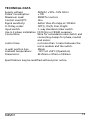
1
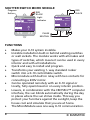
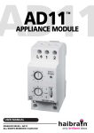
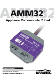
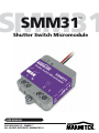
SMM31
SMM31
™
Shutter Switch Micromodule
USER MANUAL
20458/20120313 • SMM31™
ALL RIGHTS RESERVED MARMITEK ©
2
© MARMITEK
TABLE OF CONTENTS
SAFETY WARNINGS ............................................................... 4
HOW DOES MARMITEK X-10 WORK? .................................. 5
ADRESSES ............................................................................... 5
SIGNAL RANGE....................................................................... 6
SHUTTER SWITCH MICRO MODULE ...................................... 8
FUNCTIONS............................................................................. 8
INTRODUCTION...................................................................... 9
INSTALLATION ....................................................................... 9
PROGRAMMING................................................................... 10
FREQENTLY ASKED QUESTIONS.......................................... 11
TECHNICAL DATA ................................................................ 13
DECLARATION OF CONFORMITY........................................ 15
COPYRIGHTS ........................................................................ 16
SMM31
3
SAFETY WARNINGS
x
x
x
x
x
x
x
x
4
The wiring of your electrical installation is live (230 V)
and extremely dangerous. Never connect the module
when plugged into the mains. Always turn off the
main switch before starting the installation.
This product is for professional use and should be
installed by a certified installer."
To prevent short circuits, this product should only be
used inside and only in dry spaces. Do not expose the
components to rain or moisture. Do not use the
product close to a bath, swimming pool etc.
Do not expose the components of your systems to
extremely high temperatures or bright light sources.
In case of improper usage or if you have altered and
repaired the product yourself, all guarantees expire.
Marmitek does not accept responsibility in the case of
improper usage of the product or when the product is
used for purposes other than specified. Marmitek
does not accept responsibility for additional damage
other than covered by the legal product
responsibility.
This product is not a toy. Keep out of reach of
children.
Do not open the product: the device may contain live
parts. The product should only be repaired or serviced
by a qualified expert.
Automatic switching devices provide comfort, but can
also be dangerous. They can surprise people or can
ignite clothing hanging over an electric heat source.
Please be careful and take appropriate measures to
avoid accidents.
© MARMITEK
HOW DOES MARMITEK X-10 WORK?
Marmitek X-10 components use the existing mains wiring
to communicate (using Marmitek X-10 signals). You can
build a complete system using the three different kind of
components of the Marmitek X-10 System:
1. Modules: These components will receive Marmitek X-10
signals and will switch or dim the attached lamp or
appliance. Examples of these modules are lamp modules
and appliance modules. These are available as build-in,
micro, DIN rail and plug-in modules.
2. Controllers: These components will transmit Marmitek
X-10 signals and thus will control the Modules.
3. Transmitters:Wireless components like remotes. The
signals of these components will be received by a
controller with transceiver functionality (IRRF 7243, TM13,
CM15Pro…..). The Transceiver will translate the signals into
Marmitek X-10 signals on the power line.
ADRESSES
Up to a maximum of 256 different addresses can be preset.
These are subdivided into a so-called HouseCode (A to P
incl.) and a UnitCode (1 to 16 incl.). The HouseCode can
also be set on the controllers, so that the controllers and
modules become part of the same system. The address can
be set either using code dials or by pressing buttons,
depending on the type of module.
The Marmitek X-10 System uses standard commands,
which control all units with the same HouseCode at the
same time (e.g. all lights on, all units off, etc.).
SMM31
5
SIGNAL RANGE
Range of Marmitek X-10 signals over the Power Line
and how to increase the range.
The Marmitek X-10 System is based on power line
communication. The range of the Marmitek X-10 signals
very much depends on the local circumstances. On average
the range is a cable length of 80 meters.
If you have difficulties with the range of your
Marmitek X-10 signals, please pay attention to the
following facts:
1. When more than one phase is used for your electrical
system, it is necessary to couple these phases for the
Marmitek X-10 signals. For coupling you can use FD10
Phase Couplers/Filters. You only need to install a Phase
Coupler/Filter when your wall outlets and light switches
are divided over more than one phase (more than one
group is no problem). For bigger buildings or longer
distances we advice you to use an active repeater instead
of passive FD10’s.
2. It is possible that Marmitek X-10 signals are attenuated
by devices and lights which are connected to the power
line. In a normal home situation this effect is negligible
(the Marmitek X-10 system is using active gain control to
eliminate the effects). However, it is possible that a
particular device in your house is attenuating the signals so
much that the range of Marmitek X-10 signals is decreased
significantly. When you have range problems, it is wise to
try to locate the device which is attenuating the signals
simply by unplugging devices from the power line, and
testing the differences in range for your Marmitek system.
When e.g. your conclusion is that e.g. your computer
monitor is attenuating the signal, you can use a FM10
6
© MARMITEK
Plug-in Filter between the power line and the monitor to
eliminate the effects.
Known devices which can cause attenuation are:
PC Monitors
PCs with heavy internal power supplies
Old Televisions
Copiers
Fluorescent Lights
Gas Discharge Lamps (Energy Saving Lamps)
3. Some (old) devices are able to disturb the signal by
transmitting noise on the power line. Because the
Marmitek X-10 signals are transmitted on 120 kHz, only
noise on or near this frequency will have influence on the
range. When you use a FM10 Filter to connect this device
to the power line, the noise will be filtered.
4. The Marmitek X-10 protocol has several mechanism to
avoid modules to be switched on or off by other sources
than your Marmitek X-10 Controllers. However, it is
possible that the Marmitek X-10 signals are disturbed by
e.g. baby phones which are in TALK mode (continuous
transmission). When these kind of signals are present on
the power line it is possible that the Marmitek X-10 signals
will not come through.
5. The mains do not stop at the front door of your home.
Everything that is attached to mains nearby your home can
have influence on Marmitek X-10 signals (e.g. heavy
machinery). If you think that your system is influenced by
devices out of your house, it is advisable to install FD10
Phase Coupler/Filter on each phase entering the house.
These filters will block signals coming into or going out of
your house, but will also match the impedance for the
mains. Hereby make your house Marmitek X-10 compatible
for these units. The FD10’s will not only filter but will also
couple the phases (please see 1).
7
SMM31
SHUTTER SWITCH MICRO MODULE
Program
Button
SMM31
Shutter Switch Micromodule
Ad
dr
ess
Shutter Switch Micromodule
t
On
/O
ff*
Light
Indicator
In
pu
SMM31
1
2
L
/O
ff*
L2 N
On
pu
t
1
In
Ad
dr
ess
RED
BLACK
RED
BLACK
M
2
1
M
N
2
1
PHASE
NEUTRAL
M
FUNCTIONS
x
x
x
Makes your X-10 system invisible.
Invisible installation built-in behind existing switches
or wall sockets. The module works with all makes and
types of switches, which means it can be used in every
interior and with all installations.
Quick and easy to install and program.
Transforms your existing 1- way standard rocker
switch into a X-10 controllable switch.
Micromodule with built-in relay with two contacts for
connecting a 230V motor.
Can be operated remotely with an X-10 signal or
locally, fully open/closed or on every interim position.
Lowers, in combination with the CM15Pro™ computer
interface, the sun blinds automatically during the day
in places where the sun shines inside. This way you
protect your furniture against the sunlight, keep the
house cool and simulate that you are at home.
The MicroModule uses one-way X-10 communication.
8
© MARMITEK
x
x
x
x
x
INTRODUCTION
This unit allows a motorized
blind to be controlled either
manually from a 1- way
standard rocker switch
connected to the unit, or
remotely by serial Marmitek
X-10 Powerline messages sent from a suitable controller.
When controlled serially the blind can be made to go to
intermediate settings in addition to fully up or fully down
with dim and bright commands.
INSTALLATION
x
x
x
x
x
x
x
x
x
x
x
x
x
Switch off appropriate mains fuse and master switch!
Important : 230V - 50Hz - 1A per channel max.
To install the SMM31, neutral and phase are required
at the installation point.
Take the wall switch out of the wall box.
Disconnect all wires from the switch.
Pull an additional Neutral wire if it is missing.
Connect the phase and neutral wire to the “L” and
“N” terminals of the micromodule
Connect the terminal 1 of SMM31 to Motor Down,
the terminal 2 to Motor Up.
Connect the thin Black and Red wires of the built-in
module to the 1- way standard rocker switch.
Position the MicroModule against the back wall of
the wall outlet behind all the wires.
You are now able to program the MicroModule.
For more information see chapter “Programming”.
Install the 1- way standard rocker switch at its original
SMM31
9
x
place after the MicroModule is programmed.
Please note: due to heat generation, apply no more
than one module per flush socket / central socket!
PROGRAMMING.
WARNING: DO NOT FORGET TO TURN ON THE MAIN
MASTER SWITCH PRIOR TO PROGRAMMING.
Programming the address:
The factory setting for the SMM31 is to address A1.
Unlike most Marmitek X-10 Modules the SMM31 does not
have code wheels.
To change the address, the module needs to be set to the
program mode.
Press and hold the “Program” button for 5 seconds,
indicator light Turns ON, means entering “Program
mode”. Transmit the address command (xx ON or XX OFF),
at this time the indicator light goes OFF.
Warning! The MicroModule will leave the setup mode if it
doesn’t receive any commands within 30 seconds.
10
© MARMITEK
FREQENTLY ASKED QUESTIONS
What is the reason for modules to switch on/off
spontaneously?
It is possible that a Marmitek X-10 System is installed at
one of your neighbours using the same House Code. To
solve this problem try to change the House Code of your
system, or have FD10 Phase Coupler/Filter installed at your
incoming mains.
My modules will not respond to my controller.
Make sure that the House Code on all Modules and
Controllers are set to the same House Code (A .. P).
My modules will not react to my remote / sensor.
When you use a remote or sensor, you should have at least
one Transceiver, CM15Pro or Marmitek X-10 Security
Console installed in your house. These components will
translate the radio signals to the Marmitek X-10 signal on
the power line. Using several remotes and sensors, you
only need one central transceiver.
SMM31
11
Am I able to increase the range of my remotes by
using more Transceivers?
Yes, you can use more than one Transceiver in your home
when the range of your remotes is not sufficient. The
transceiver is using
so called collision detection to prevent signals to be
disturbed when more than one transceiver is transmitting.
The Transceivers will wait for a quite power line before
transmitting their data. To prevent your Marmitek X-10
System to become slow or to prevent dimming from
becoming less smooth, make sure that the transceiver units
are placed as far away from each other as possible.
Do you have other questions that have not been
resolved by the above information? Please go to
www.marmitek.com
12
© MARMITEK
TECHNICAL DATA
Supply voltage:
Power Consumption:
Maximum Load:
Control Load QTY:
Signal sensitivity:
X-10 Key codes:
Input switch:
Use in 3 phase installation
Connections
control lines
in wall junction box
Ambient temperature:
Dimensions:
230VAC +10% -10% 50 Hz
< 1W
200W for motors
One
better than 25 mVpp at 120 kHz
Off(1), On(2), Dim, Bright
1- way standard rocker switch
FD10 (3x) or FKX40 necessary
Wire for a standard rocker switch and
connecting clamps for phase, neutral
and motor.
not more than 1 meter between the
micro module and the switch.
50mm
-10°C tot +50°C (Operation)
43.25mm x 47mm x 18.9mm
Specifications may be modified without prior notice.
SMM31
13
Environmental Information for Customers
in the European Union
European Directive 2002/96/EC requires that the
equipment bearing this symbol on the product
and/or its packaging must not be disposed of
with unsorted municipal waste. The symbol indicates that
this product should be disposed of separately from regular
household waste streams. It is your responsibility to
dispose of this and other electric and electronic equipment
via designated collection facilities appointed by the
government or local authorities. Correct disposal and
recycling
will
help
prevent
potential
negative
consequences to the environment and human health. For
more detailed information about the disposal of your old
equipment, please contact your local authorities, waste
disposal service, or the shop where you purchased the
product.
14
© MARMITEK
DECLARATION OF CONFORMITY
Hereby, Marmitek BV, declares that this SMM31 is in
compliance with the essential requirements and other
relevant provisions of the following Directives:
Directive 2004/108/ec of the european parliament and of
the council of 15 December 2004 on the approximation of
the laws of the Member States relating to electromagnetic
compatibility
Directive 2006/95/EC of the European Parliament and of
the Council of 12 December 2006 on the harmonisation of
the laws of Member States relating to electrical equipment
designed for use within certain voltage limits
Directive 2002/95/EC of the European Parliament and of
the Council of 27 January 2003 on the restriction of the use
of certain hazardous substances in electrical and electronic
equipment
SMM31
15
COPYRIGHTS
Marmitek is a trademark of Pattitude B.V.
SMM31™ is a trademark of Marmitek B.V.
All rights reserved.
Copyright and all other proprietary rights in the content
(including but not limited to model numbers, software,
audio, video, text and photographs) rests with Marmitek
B.V. Any use of the Content, but without limitation,
distribution, reproduction, modification, display or
transmission without the prior written consent of
Marmitek is strictly prohibited. All copyright and other
proprietary notices shall be retained on all reproductions.
16
© MARMITEK