1
No. CP-SP-1147E
SDC15
Single Loop Controller
User's Manual
for
Basic Operation
Thank you for purchasing the SDC15
Single Loop Controller.
This manual contains information for
ensuring correct use of the SDC15. It
also provides necessary information for
installation, maintenance, and troubleshooting.
This manual should be read by those
who design and maintain devices that
use the SDC15.
Be sure to keep this manual nearby for
handy reference.
RESTRICTIONS ON USE
This product has been designed, developed and manufactured for general-purpose
application in machinery and equipment.
Accordingly, when used in applications outlined below, special care should be taken to
implement a fail-safe and/or redundant design concept as well as a periodic
maintenance program.
• Safety devices for plant worker protection
• Start/stop control devices for transportation and material handling machines
• Aeronautical machines
• Aerospace machines
• Control devices for nuclear reactors
Never use this product in applications where human safety may be put at risk.
REQUEST
Ensure that this User's Manual is handed over to the user before the
product is used.
Copying or duplicating this User's Manual in part or in whole is forbidden. The information and specifications in this User's Manual are subject to change without notice.
Considerable effort has been made to ensure that this User's Manual is
free from inaccuracies and omissions.
If you should find any inaccuracies or omissions, please contact
Yamatake Corporation.
In no event is Yamatake Corporation liable to anyone for any indirect,
special or consequential damages as a result of using this product.
©2003 by Yamatake Corporation–ALL RIGHTS RESERVED
SAFETY REQUIREMENTS
To reduce risk of electric shock which could cause personal injury, follow all safety
notices in this documentation.
This symbol warns the user of a potential shock hazard where hazardous live voltages
may be accessible.
•
•
•
•
•
If the equipment is used in a manner not specified by the manufacturer, the protection
provided by the equipment must be impaired.
Do not replace any component (or part) not explicitly specified as replaceable by your
supplier.
All wiring must be in accordance with local norms and carried out by authorized and
experienced personnel.
A switch in the main supply is required near the equipment.
Main power supply wiring requires a (T) 200mA, 250V fuse(s) (IEC 127).
EQUIPMENT RATINGS
Supply voltages:
100 to 240V (operating power supply voltage 85 to 264Vac)
Frequency:
50/60Hz
Power consumption:
12VA maximum
EQUIPMENT CONDITIONS
Do not operate the instrument in the presence of flammable liquids or vapors.
Operation of any electrical instrument in such an environment constitutes a safety hazard.
Temperature:
0 to 50˚C
Humidity:
10 to 90%RH (no condensation)
Vibration:
2m/s2 (10 to 60Hz)
Over-voltage category:
Category II (IEC60364-4-443, IEC60664-1)
Pollution degree:
Pollution degree 2
EQUIPMENT INSTALLATION
The controller must be mounted into a panel to limit operator access to the rear terminal.
Specifications of common mode voltage: The common mode voltages of all I/O except for main
supply and relay outputs are less than 33Vr.m.s, 46.7V peak and 70Vdc.
APPLICABLE STANDARDS
EN61010-1, EN61326-1
i
SAFETY PRECAUTIONS
■ About Icons
Safety precautions are for ensuring safe and correct use of this product, and for
preventing injury to the operator and other people or damage to property. You
must observe these safety precautions. The safety precautions described in this
manual are indicated by various icons.
As the following describes the icons and their meanings, be sure to read and
understand the descriptions before reading this manual:
WARNING
CAUTION
Warnings are indicated when mishandling this product might
result in death or serious injury to the user.
Cautions are indicated when mishandling this product might
result in minor injury to the user, or only physical damage to
this product.
■ Examples
Triangles warn the user of a possible danger that may be caused by
wrongful operation or misuse of this product.
These icons graphically represent the actual danger. (The example on
the left warns the user of the danger of electric shock.)
White circles with a diagonal bar notify the user that specific actions are
prohibited to prevent possible danger.
These icons graphically represent the actual prohibited action. (The
example on the left notifies the user that disassembly is prohibited.)
Black filled-in circles instruct the user to carry out a specific obligatory
action to prevent possible danger.
These icons graphically represent the actual action to be carried out.
(The example on the left instructs the user to remove the plug from the
outlet.)
ii
WARNING
Do not disassemble the SDC15.
Doing so might cause electric shock or faulty operation.
Before wiring, or removing/mounting the SDC15, be sure to turn the
power OFF.
Failure to do so might cause electric shock.
Do not touch electrically charged parts such as the power terminals.
Doing so might cause electric shock.
CAUTION
Use the SDC15 within the operating ranges recommended in the
specifications (temperature, humidity, voltage, vibration, shock,
mounting direction, atmosphere, etc.).
Do not block ventilation holes.
Doing so might cause fire or faulty operation.
Wire the SDC15 properly according to predetermined standards.
Also wire the SDC15 using specified power leads according to
recognized installation methods.
Failure to do so might cause electric shock, fire or faulty operation.
Do not allow lead clippings, chips or water to enter the controller case.
Doing so might cause fire or faulty operation.
Firmly tighten the terminal screws at the torque listed in the
specifications.
Insufficient tightening of terminal screws might cause electric shock or
fire.
Do not use unused terminals on the SDC15 as relay terminals.
Doing so might cause electric shock, fire, or faulty operation.
We recommend attaching the terminal cover (sold separately) after
wiring the SDC15.
Failure to do so might cause electric shock, fire, or faulty operation.
Continued use of the relays after the recommended service life has
expired might cause fire or faulty operation.
Failure to do so might cause fire or faulty operation.
Use Yamatake Corporation's "SURGENON" if there is the risk of power
surges caused by lightning.
Doing so might cause fire or faulty operation.
Do not make incorrect connections. If the cables are connected
incorrectly, this might cause the unit to malfunction.
The controller does not function for approximately 6 sec. after the
power has been turned ON. Great care should be taken when the relay
output from the controller is used as interlock signals.
iii
CAUTION
The part between the control output 1 and control output 2 is not
isolated. When necessary, use an appropriate isolator.
Do not connect multiple loader cables to multiple units from one
personal computer. The current coming from other circuits might
cause the PV value indication error to occur.
Do not connect any terminating resistor to both ends of the
communication path when performing the RS-485 wiring.
Doing so might cause the communication to fail.
Always mount a switch for shut-down of the main power of this unit in
an easily accessible area of the operator when performing electric
wiring of this unit. Additionally, connect a slow-action type (T) fuse
having a rated current of 0.2A and rated voltage of 250V to the wiring
for the instrument power supply of the AC power supply model.
(IEC127)
Do not operate the key with a propelling pencil or sharp-tipped object.
Doing so might cause faulty operation.
This unit incorporates the self-tuning function without use of control
constant settings in addition to the ON/OFF control and conventional
PID control. This self-tuning control monitors and studies the
characteristics of the control subject even if the SP value is changed or
external disturbance occurs in order to automatically calculate the
control constants. This ensures stable control all the time.
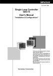
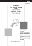
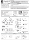
Important notice
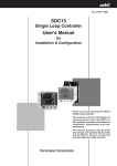
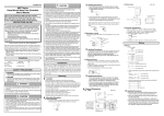
The protective film is adhered to the front console of this unit to protect the surface.
After the installation and wiring work has been completed, stick a scotch tape to the corner of the console and pull it
out in the direction indicated by an arrow to peel off the protective film.
Handling Precautions
If you attempt to peel off the protective film with your fingernail, this might
cause damage to the console.
Scotch tape
Pull out.
mo
de
rdy
pa
ra
ma
n
ev
1
ev
2
ev
3
ot1
ot2
iv
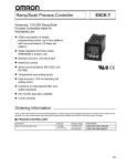
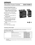
The Role of This Manual
Four different manuals in total are available for the SDC15 (hereafter referred to as "this unit") Single Loop
Controller. Read appropriate manuals according to your requirements. If you do not have your required manual,
contact Yamatake Corporation or its dealer.
Additionally, you can download necessary manuals from "http://www.yamatake.com".
The user level of this unit can be selected from three levels, "Simple configuration", "Standard configuration", and
"High function configuration". This manual describes the functions you can set up only with "Simple
configuration". If more advanced application is needed, refer to SDC15 Single Loop Controller User's Manual for
Installation & Configuration (CP-SP-1148E).
User’s
Manual
ING
WARN
N
CAUTIO
SDC15 Single Loop Controller User's Manual for Installation
Manual No. CP-UM-5287E
NG
WARNI
N
CAUTIO
This manual is supplied with the product. Personnel in charge of design
and/or manufacture of a system using this unit must thoroughly read this
manual. This manual describes the safety precautions, installation, wiring,
and primary specifications. For further information about operation, refer to
other manuals, Basic Operation and/or Installation & Configuration.
SDC15 Single Loop Controller User's Manual for Basic Operation
Manual No. CP-SP-1147E
This manual. This manual is optional (sold separately). The manual
describes the functions you can set up only with "Simple configuration".
Personnel in charge of design, manufacture, operation, and/or maintenance
of a system using this unit must thoroughly read this manual. This manual
describes the installation, wiring, major functions and settings, operating
procedures, troubleshooting, and detailed specifications.
SDC15 Single Loop Controller User's Manual for Installation &
Configuration
Manual No. CP-SP-1148E
This manual is optional (sold separately). The manual describes the
hardware and all functions of this unit. Personnel in charge of design,
manufacture, operation, and/or maintenance of a system using this unit and
those in charge of communication software of a system using the
communication functions of this unit must thoroughly read this manual.
This manual also describes the installation, wiring, connections for
communication, all functions and settings of this unit, operating procedures,
communication with host station, such as personal computer,
communication addresses, troubleshooting, and detailed specifications.
SLP-C35 Smart Loader Package for SDC15/25/26/35/36 Single Loop
Controller User's Manual
Manual No. CP-UM-5290E
This manual is supplied with the Smart Loader Package. The manual
describes the software used to make various settings for SDC15/25/26/35/
36 using a personal computer. Personnel in charge of design or setting of
a system using SDC15/25/26/35/36 must thoroughly read this manual. The
manual describes installation of the software into a personal computer,
operation of the personal computer, various functions, and setup
procedures.
v
Organization of This User's Manual
This manual is organized as follows:
Chapter 1. OVERVIEW
This chapter describes the applications, features, model selection guide, and part
names and functions of this unit. Since the part names described in this chapter
are used in the subsequent descriptions, the part names and functions of this unit
must be understood correctly in this chapter.
Chapter 2. OUTLINE OF FUNCTIONS
This chapter describes the outline and operation flow of the functions of this unit.
Chapter 3. INSTALLATION
This chapter describes the environmental conditions, installation dimensions,
installation procedures, and necessary tools when installing this unit.
Chapter 4. WIRING
This chapter describes the wiring procedures, wiring precautions, and connection
examples.
Chapter 5. SETTINGS BEFORE STARTING OPERATION
This chapter describes the items necessary to set up before starting operation and
setting procedures.
Chapter 6. SETTINGS DURING OPERATION
This chapter describes the setting items and setting procedures when performing
the control with this unit built-into the customer’s system.
Chapter 7. LIST OF SIMPLE CONFIGURATION DISPLAY ITEMS
This chapter shows the list of the setting items when operating this unit with
"Simple configuration".
Chapter 8. PID CONTROL TUNING
This chapter describes the auto tuning function and self-tuning function of this
unit.
Chapter 9. MAINTENANCE AND TROUBLESHOOTING
This chapter describes the maintenance and inspection of this unit, as well as
troubleshooting.
Chapter 10. DISPOSAL
This chapter describes safety precautions and how to dispose of this unit when the
unit is no longer used.
Chapter 11. SPECIFICATIONS
This chapter describes the general specifications, performance specifications, and
optional parts of this unit.
vi
Contents
SAFETY REQUIREMENTS
SAFETY PRECAUTIONS
Important Notice
The Role of This Manual
Organization of This User's Manual
Conventions Used in This Manual
Chapter 1.
OVERVIEW
1-1 Overview • • • • • • • • • • • • • • • • • • • • • • • • • • • • • • • • • • • • • • • • • • • • • • • • • • • • • • • • • • • • • • • • • • • 1-1
■ Model selection table • • • • • • • • • • • • • • • • • • • • • • • • • • • • • • • • • • • • • • • • • • • • • • • • • • 1-2
■ Accessories and optional parts • • • • • • • • • • • • • • • • • • • • • • • • • • • • • • • • • • • • • • • • 1-3
1-2 Part Names and Functions • • • • • • • • • • • • • • • • • • • • • • • • • • • • • • • • • • • • • • • • • • • • • • • • • 1-4
■ Main body and console • • • • • • • • • • • • • • • • • • • • • • • • • • • • • • • • • • • • • • • • • • • • • • • • 1-4
■ Bottom panel • • • • • • • • • • • • • • • • • • • • • • • • • • • • • • • • • • • • • • • • • • • • • • • • • • • • • • • • • • 1-5
■ Rear panel • • • • • • • • • • • • • • • • • • • • • • • • • • • • • • • • • • • • • • • • • • • • • • • • • • • • • • • • • • • • • 1-6
Chapter 2.
OUTLINE OF FUNCTIONS
2-1 Input/Output Configuration • • • • • • • • • • • • • • • • • • • • • • • • • • • • • • • • • • • • • • • • • • • • • • • • 2-1
2-2 Key Operation • • • • • • • • • • • • • • • • • • • • • • • • • • • • • • • • • • • • • • • • • • • • • • • • • • • • • • • • • • • • • 2-2
■ Data setting procedures • • • • • • • • • • • • • • • • • • • • • • • • • • • • • • • • • • • • • • • • • • • • • • • 2-3
■ [mode] key operating procedures • • • • • • • • • • • • • • • • • • • • • • • • • • • • • • • • • • • • • • 2-5
2-3 Operation Modes • • • • • • • • • • • • • • • • • • • • • • • • • • • • • • • • • • • • • • • • • • • • • • • • • • • • • • • • • • 2-6
Chapter 3.
INSTALLATION
■
■
■
■
Chapter 4.
Installation place • • • • • • • • • • • • • • • • • • • • • • • • • • • • • • • • • • • • • • • • • • • • • • • • • • • • • • • 3-1
External Dimensions • • • • • • • • • • • • • • • • • • • • • • • • • • • • • • • • • • • • • • • • • • • • • • • • • • • 3-2
Panel Cutout Dimensions • • • • • • • • • • • • • • • • • • • • • • • • • • • • • • • • • • • • • • • • • • • • • • 3-2
Mounting procedures • • • • • • • • • • • • • • • • • • • • • • • • • • • • • • • • • • • • • • • • • • • • • • • • • • 3-3
WIRING
4-1 Wiring• • • • • • • • • • • • • • • • • • • • • • • • • • • • • • • • • • • • • • • • • • • • • • • • • • • • • • • • • • • • • • • • • • • • • • 4-1
■ Terminal assignment label symbols • • • • • • • • • • • • • • • • • • • • • • • • • • • • • • • • • • • 4-2
■ Wiring Precautions • • • • • • • • • • • • • • • • • • • • • • • • • • • • • • • • • • • • • • • • • • • • • • • • • • • • 4-2
■ Connection of open collector output to digital input • • • • • • • • • • • • • • • • • • • 4-5
■ Connection of (RS-485) communication cable • • • • • • • • • • • • • • • • • • • • • • • • • 4-5
■ Connection with SSR (solid state relay) • • • • • • • • • • • • • • • • • • • • • • • • • • • • • • • • 4-7
■ Noise Preventive Measures • • • • • • • • • • • • • • • • • • • • • • • • • • • • • • • • • • • • • • • • • • • 4-10
4-2 Recommended Cables• • • • • • • • • • • • • • • • • • • • • • • • • • • • • • • • • • • • • • • • • • • • • • • • • • • • 4-11
vii
Chapter 5.
SETTINGS BEFORE STARTING OPERATION
5-1 PV Input • • • • • • • • • • • • • • • • • • • • • • • • • • • • • • • • • • • • • • • • • • • • • • • • • • • • • • • • • • • • • • • • • • • 5-2
■ PV range type setup • • • • • • • • • • • • • • • • • • • • • • • • • • • • • • • • • • • • • • • • • • • • • • • • • • • 5-2
■ Temperature unit setup • • • • • • • • • • • • • • • • • • • • • • • • • • • • • • • • • • • • • • • • • • • • • • • • 5-4
■ Decimal point position setup • • • • • • • • • • • • • • • • • • • • • • • • • • • • • • • • • • • • • • • • • • 5-5
■ PV input range low limit/high limit setup • • • • • • • • • • • • • • • • • • • • • • • • • • • • • • • 5-6
5-2 Control • • • • • • • • • • • • • • • • • • • • • • • • • • • • • • • • • • • • • • • • • • • • • • • • • • • • • • • • • • • • • • • • • • • • • 5-7
■ Control method setup • • • • • • • • • • • • • • • • • • • • • • • • • • • • • • • • • • • • • • • • • • • • • • • • • • 5-7
■ Control action (Direct/Reverse) setup • • • • • • • • • • • • • • • • • • • • • • • • • • • • • • • • • • 5-8
■ Heat/Cool control selection setup • • • • • • • • • • • • • • • • • • • • • • • • • • • • • • • • • • • • • • 5-9
■ Heat/Cool control dead band setup • • • • • • • • • • • • • • • • • • • • • • • • • • • • • • • • • • • 5-10
■ LSP system group setup• • • • • • • • • • • • • • • • • • • • • • • • • • • • • • • • • • • • • • • • • • • • • • 5-12
5-3 Internal Event • • • • • • • • • • • • • • • • • • • • • • • • • • • • • • • • • • • • • • • • • • • • • • • • • • • • • • • • • • • • • 5-13
■ Event operation type setup • • • • • • • • • • • • • • • • • • • • • • • • • • • • • • • • • • • • • • • • • • • 5-19
■ Event Direct/Reverse, standby, and Event state at READY setup • • • • • 5-20
■ Event main setting setup • • • • • • • • • • • • • • • • • • • • • • • • • • • • • • • • • • • • • • • • • • • • • 5-21
■ Event sub-setting setup • • • • • • • • • • • • • • • • • • • • • • • • • • • • • • • • • • • • • • • • • • • • • • 5-22
■ Event hysteresis setup • • • • • • • • • • • • • • • • • • • • • • • • • • • • • • • • • • • • • • • • • • • • • • • 5-23
5-4 CT (Current Transformer) Input • • • • • • • • • • • • • • • • • • • • • • • • • • • • • • • • • • • • • • • • • • • 5-24
■ CT type setup • • • • • • • • • • • • • • • • • • • • • • • • • • • • • • • • • • • • • • • • • • • • • • • • • • • • • • • • • 5-24
■ CT output setup• • • • • • • • • • • • • • • • • • • • • • • • • • • • • • • • • • • • • • • • • • • • • • • • • • • • • • • 5-25
■ CT wait time before measurement setup • • • • • • • • • • • • • • • • • • • • • • • • • • • • • • 5-26
5-5 Continuous Output • • • • • • • • • • • • • • • • • • • • • • • • • • • • • • • • • • • • • • • • • • • • • • • • • • • • • • • 5-27
■ Output range setup • • • • • • • • • • • • • • • • • • • • • • • • • • • • • • • • • • • • • • • • • • • • • • • • • • 5-27
■ Output type setup• • • • • • • • • • • • • • • • • • • • • • • • • • • • • • • • • • • • • • • • • • • • • • • • • • • • • 5-28
■ Output scaling low limit/high limit setup • • • • • • • • • • • • • • • • • • • • • • • • • • • • • • 5-29
■ MV scaling range • • • • • • • • • • • • • • • • • • • • • • • • • • • • • • • • • • • • • • • • • • • • • • • • • • • • • 5-30
5-6 Communication• • • • • • • • • • • • • • • • • • • • • • • • • • • • • • • • • • • • • • • • • • • • • • • • • • • • • • • • • • • 5-31
■ Communication mode setup • • • • • • • • • • • • • • • • • • • • • • • • • • • • • • • • • • • • • • • • • • 5-31
■ Station address setup • • • • • • • • • • • • • • • • • • • • • • • • • • • • • • • • • • • • • • • • • • • • • • • • 5-32
■ Transmission speed setup • • • • • • • • • • • • • • • • • • • • • • • • • • • • • • • • • • • • • • • • • • • • 5-33
■ Data format (data length) setup • • • • • • • • • • • • • • • • • • • • • • • • • • • • • • • • • • • • • • • 5-34
■ Data format (parity) setup • • • • • • • • • • • • • • • • • • • • • • • • • • • • • • • • • • • • • • • • • • • • • 5-35
■ Data format (stop bit) setup • • • • • • • • • • • • • • • • • • • • • • • • • • • • • • • • • • • • • • • • • • • 5-36
5-7 Key Operation • • • • • • • • • • • • • • • • • • • • • • • • • • • • • • • • • • • • • • • • • • • • • • • • • • • • • • • • • • • • 5-37
■ Mode key function setup• • • • • • • • • • • • • • • • • • • • • • • • • • • • • • • • • • • • • • • • • • • • • • 5-37
■ User level setup• • • • • • • • • • • • • • • • • • • • • • • • • • • • • • • • • • • • • • • • • • • • • • • • • • • • • • • 5-38
5-8 DI Assignment • • • • • • • • • • • • • • • • • • • • • • • • • • • • • • • • • • • • • • • • • • • • • • • • • • • • • • • • • • • • 5-39
■ Internal contact operation type setup • • • • • • • • • • • • • • • • • • • • • • • • • • • • • • • • • 5-39
Chapter 6.
6-1
SETTINGS DURING OPERATION
SP • • • • • • • • • • • • • • • • • • • • • • • • • • • • • • • • • • • • • • • • • • • • • • • • • • • • • • • • • • • • • • • • • • • • • • • • • 6-1
■ SP setup in operation display mode • • • • • • • • • • • • • • • • • • • • • • • • • • • • • • • • • • • 6-1
■ LSP No. setup • • • • • • • • • • • • • • • • • • • • • • • • • • • • • • • • • • • • • • • • • • • • • • • • • • • • • • • • • • 6-2
■ SP setup in parameter setting display mode • • • • • • • • • • • • • • • • • • • • • • • • • • • 6-3
viii
6-2 Operation Display other than SP • • • • • • • • • • • • • • • • • • • • • • • • • • • • • • • • • • • • • • • • • • • 6-4
■ MV (manipulated variable) display and setup • • • • • • • • • • • • • • • • • • • • • • • • • • 6-4
■ Heat MV (manipulated variable) and cool MV
(manipulated variable) display • • • • • • • • • • • • • • • • • • • • • • • • • • • • • • • • • • • • • • • • • 6-5
■ AT (auto tuning) progress display • • • • • • • • • • • • • • • • • • • • • • • • • • • • • • • • • • • • • 6-5
■ CT (current transformer) input 1/2 current value display • • • • • • • • • • • • • • • 6-6
6-3 Mode • • • • • • • • • • • • • • • • • • • • • • • • • • • • • • • • • • • • • • • • • • • • • • • • • • • • • • • • • • • • • • • • • • • • • • • 6-7
■ AUTO/MANUAL mode selection setup • • • • • • • • • • • • • • • • • • • • • • • • • • • • • • • • • 6-7
■ RUN/READY mode selection setup • • • • • • • • • • • • • • • • • • • • • • • • • • • • • • • • • • • • 6-8
■ AT (auto tuning) Stop/Start selection setup • • • • • • • • • • • • • • • • • • • • • • • • • • • • 6-9
■ Release all DO (digital output) latches setup • • • • • • • • • • • • • • • • • • • • • • • • • 6-10
■ Communication DI (digital input) 1 setup • • • • • • • • • • • • • • • • • • • • • • • • • • • • • 6-11
6-4 PID • • • • • • • • • • • • • • • • • • • • • • • • • • • • • • • • • • • • • • • • • • • • • • • • • • • • • • • • • • • • • • • • • • • • • • • 6-12
■ P-1 (proportional band) setup• • • • • • • • • • • • • • • • • • • • • • • • • • • • • • • • • • • • • • • • • 6-12
■ I-1 (Integral time) setup • • • • • • • • • • • • • • • • • • • • • • • • • • • • • • • • • • • • • • • • • • • • • • • 6-13
■ d-1 (Derivative time) setup • • • • • • • • • • • • • • • • • • • • • • • • • • • • • • • • • • • • • • • • • • • • 6-14
■ rE-1 (Manual reset) setup • • • • • • • • • • • • • • • • • • • • • • • • • • • • • • • • • • • • • • • • • • • • • 6-15
■ P-1C (Proportional band - cool) setup • • • • • • • • • • • • • • • • • • • • • • • • • • • • • • • • 6-16
■ I-1C (Integral time - cool) setup • • • • • • • • • • • • • • • • • • • • • • • • • • • • • • • • • • • • • • • 6-17
■ d-1C (Derivative time - cool) setup • • • • • • • • • • • • • • • • • • • • • • • • • • • • • • • • • • • • 6-18
6-5 Other Parameter Setup • • • • • • • • • • • • • • • • • • • • • • • • • • • • • • • • • • • • • • • • • • • • • • • • • • • 6-19
■ ON/OFF control differential setup • • • • • • • • • • • • • • • • • • • • • • • • • • • • • • • • • • • • • 6-19
■ PV filter setup • • • • • • • • • • • • • • • • • • • • • • • • • • • • • • • • • • • • • • • • • • • • • • • • • • • • • • • • • 6-20
■ PV bias setup • • • • • • • • • • • • • • • • • • • • • • • • • • • • • • • • • • • • • • • • • • • • • • • • • • • • • • • • • 6-21
■ Time proportional cycle time 1/2 setup • • • • • • • • • • • • • • • • • • • • • • • • • • • • • • • 6-22
■ MV low limit/high limit at AT (auto tuning) • • • • • • • • • • • • • • • • • • • • • • • • • • • • 6-23
■ AT type setup • • • • • • • • • • • • • • • • • • • • • • • • • • • • • • • • • • • • • • • • • • • • • • • • • • • • • • • • • 6-24
■ Key lock setup • • • • • • • • • • • • • • • • • • • • • • • • • • • • • • • • • • • • • • • • • • • • • • • • • • • • • • • • 6-25
■ Password lock function • • • • • • • • • • • • • • • • • • • • • • • • • • • • • • • • • • • • • • • • • • • • • • • 6-26
■ Password display setup • • • • • • • • • • • • • • • • • • • • • • • • • • • • • • • • • • • • • • • • • • • • • • 6-27
■ Passwords (1A, 2A, 1B, 2B) setup • • • • • • • • • • • • • • • • • • • • • • • • • • • • • • • • • • • • 6-28
Chapter 7.
LIST OF SIMPLE CONFIGURATION DISPLAY ITEMS
7-1 List of Operation Displays • • • • • • • • • • • • • • • • • • • • • • • • • • • • • • • • • • • • • • • • • • • • • • • • • 7-1
7-2 List of Parameter Setting Displays • • • • • • • • • • • • • • • • • • • • • • • • • • • • • • • • • • • • • • • • • 7-2
7-3 List of Setup Setting Displays • • • • • • • • • • • • • • • • • • • • • • • • • • • • • • • • • • • • • • • • • • • • • 7-5
Chapter 8.
PID CONTROL TUNING
8-1 AT (auto tuning) Function • • • • • • • • • • • • • • • • • • • • • • • • • • • • • • • • • • • • • • • • • • • • • • • • • 8-2
■ Starting procedures • • • • • • • • • • • • • • • • • • • • • • • • • • • • • • • • • • • • • • • • • • • • • • • • • • • • 8-2
■ Stopping procedures • • • • • • • • • • • • • • • • • • • • • • • • • • • • • • • • • • • • • • • • • • • • • • • • • • 8-2
8-2 ST (Self-tuning) Function • • • • • • • • • • • • • • • • • • • • • • • • • • • • • • • • • • • • • • • • • • • • • • • • • • 8-4
■ Starting procedures • • • • • • • • • • • • • • • • • • • • • • • • • • • • • • • • • • • • • • • • • • • • • • • • • • • • 8-4
■ Stopping procedures • • • • • • • • • • • • • • • • • • • • • • • • • • • • • • • • • • • • • • • • • • • • • • • • • • 8-5
8-3 Precautions for ST (Self-tuning) • • • • • • • • • • • • • • • • • • • • • • • • • • • • • • • • • • • • • • • • • • • 8-6
ix
Chapter 9.
MAINTENANCE AND TROUBLESHOOTING
■ Maintenance • • • • • • • • • • • • • • • • • • • • • • • • • • • • • • • • • • • • • • • • • • • • • • • • • • • • • • • • • • • 9-1
■ Alarm display and corrective action • • • • • • • • • • • • • • • • • • • • • • • • • • • • • • • • • • • 9-1
■ Operation in case of PV input failure • • • • • • • • • • • • • • • • • • • • • • • • • • • • • • • • • • • 9-2
Chapter 10. DISPOSAL
Chapter 11. SPECIFICATIONS
■ Specifications • • • • • • • • • • • • • • • • • • • • • • • • • • • • • • • • • • • • • • • • • • • • • • • • • • • • • • • • 11-1
■ Accessories and optional parts • • • • • • • • • • • • • • • • • • • • • • • • • • • • • • • • • • • • • • • 11-4
Appendix
Glossary • • • • • • • • • • • • • • • • • • • • • • • • • • • • • • • • • • • • • • • • • • • • • • • • • • • • • • • • • • Appendix-1
Index
x
Conventions Used in This Manual
The following conventions are used in this manual:
Handling Precautions
: Handling Precautions indicate items that the user should pay attention to
when handling the SDC15.
Note
: Notes indicate useful information that the user might benefit by knowing.
: This indicates the item or page that the user is requested to refer to.
(1), (2), (3)
: The numbers with the parenthesis indicate steps in a sequence or
indicate corresponding parts in an explanation.
[para], [mode] etc.
: These indicate keys on the keyboard.
>>
: This indicates the operation results and the status after operation.
● Numeric value and character display on LED
Numeric values The 7-segment LED expresses numeric values as follows:
0
1
2
3
4
5
6
7
8
9
Alphabetical characters
The 7-segment LED expresses alphabetical characters as follows:
There are some alphabetical characters, which are not displayed on
the LED.
A
B
C
D
E
a
b
c
d
e
F
G
H
I
J
f
g
h
i
j
K
L
M
N
O
k
l
m
n
o
P
Q
R
S
T
p
q
r
s
t
U
V
Y
Z
–
u
v
y
z
Handling Precautions
As shown above, numeric value "2" and alphabetic character "Z" are
shown in the same manner.
Accordingly, numeric value "5" and alphabetic character "S", as well as
numeric value "9" and alphabetic character "Q" are also shown in the
same manner.
xi
Chapter 1.
1 - 1
OVERVIEW
Overview
This unit is a compact controller having a mask of 48 X 48 mm and provides the following features:
• The depth is only 60 mm, providing the excellent space-saving.
• The front panel is only 2 mm thick. This ensures the excellent thin design.
• The display panel is large. This provides excellent visibility.
• [mode] key, [para] key, and digit-shift keys are provided on the front panel.
This ensures easy setup operation.
• Various input types are available, thermocouples (K, J, E, T, R, S, B, N, PLII,
WRe5-26, DIN U, DIN L), RTDs (Pt100, JPt100), current signals (4 to
20mAdc, 0 to 20mAdc), and voltage signals (0 to 1Vdc, 1 to 5Vdc, 0 to 5Vdc,
and 0 to 10Vdc).
• For control outputs, relay, voltage pulse, and current output are provided.
Additionally, these control outputs can be combined for the 2nd control output.
• The unit can be made applicable to the heat/cool control using the 2nd control
output and/or event relay.
• ON/OFF control, fixed PID, and self-tuning control can be performed.
• In addition to the PID control, two algorithms, RationaLOOP and Just-FiTTER,
are mounted. This ensures excellent controllability.
• With optional functions, a combination among 3-event points or 2-event points
(independent contacts), 2-point CT input, 2-point digital input, and/or RS-485
can be selected.
• The personal computer loader port is provided as standard function. The setup
can be made easily with use of the personal computer loader.
• Use of optional Smart Loader Package (SLP-C35) makes it possible to easily
perform the read/write operation of the parameters.
In addition to the table format setup, the operation and control status can be
monitored using the trend display. This unit can be operated without use of
program on the host unit.
• The unit is applicable to the IEC directive and the CE marking is put on the
unit.
(Applicable standards: EN61010-1 and EN61326-1)
1-1
Chapter 1. OVERVIEW
■ Model selection table
The following shows the model selection table of this unit:
Basic
model No. Mounting
Control
output
Power
supply
PV input
Option
Additional
treatment
Specifications
C15
(Note 1)
T
Panel mount type
S
Socket mount type
Control output 1
(Note 2)
R0
Control output 2
Relay contact output NO Relay contact output NC
V0
Voltage pulse output
(for SSR drive)
None
(Note 3)
VC
Voltage pulse output
(for SSR drive)
Current output
(Note 3)
VV
Voltage pulse output
(for SSR drive)
Voltage pulse output
(for SSR drive)
C0
Current output
None
(Note 3)
CC
Current output
Current output
T
Thermocouple input
(K, J, E, T, R, S, B, N, PLII, Wre5-26, DIN U, DIN L)
R
RTD input (Pt100/JPt100)
L
DC voltage/DC current input (0 to 1Vdc, 1 to 5Vdc,
0 to 5Vdc, 0 to 10Vdc, 0 to 20mAdc, 4 to 20mAdc)
A
AC Model (100 to 240Vac)
D
DC Model (24Vac / 24 to 48Vdc)
00
None
01
Event relay output: 3 points
(Note 3,4)
02
Event relay output: 3 points
Current transformer input: 2 points
Digital input: 2 points
(Note 3,4)
03
Event relay output: 3 points
Current transformer input: 2 points
RS-485 communication
(Note 5)
04
Event relay output: 2 points
(independent contact)
(Note 3,4,5)
05
Event relay output: 2 points
(independent contact)
Current transformer input: 2 points
Digital input: 2 points
(Note 3,4,5)
06
Event relay output: 2 points
(independent contact)
Current transformer input: 2 points
RS-485 communication
Note 1.
Socket sold separately
Note 2.
Only 1a contact is applicable for C15S
Note 3.
Can not be selected for the C15S
D0
Inspection Certificate provided
Note 4.
Current transformer sold separately
Y0
Complying with the traceability certification
Note 5.
Can not be selected for DC Model
1-2
00
No additional processing
Chapter 1. OVERVIEW
■ Accessories and optional parts
Name
Model No.
Mounting bracket (for C15T)
81446403-001 (Accessory)
Gasket
81409657-001 (Accessory)
Current transformer (5.8mm hole dia.)
QN206A
Current transformer (12mm hole dia.)
QN212A
Socket (for C15S)
81446391-001
Hard cover
81446442-001
Soft cover
81446443-001
Terminal cover
81446898-001
Smart Loader Package
SLP-C35J50
1-3
Chapter 1. OVERVIEW
1 - 2
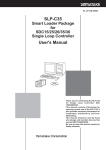
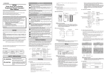
Part Names and Functions
■ Main body and console
Console
SDC15
pv
Upper display
sp
[mode] key
mo
Lower Display
mode
de
rdy
man
ev1
ev2
ev3
ot1
Mode indicator
ot2
rdy
pa
ma
ra
para
n
ev
1
ev
2
ev
3
ot1
[<], [ ], and [ ] keys
<
Console
[para] key
<
ot2
Main body
Main body: Contains the electric circuit for I/O signals of measuring instruments,
CPU, and memory.
Console: Contains the display panel showing numeric value and status, and
operation keys.
● Detailed description of console
[mode] key
When this key is kept pressed for 1 sec. or longer in the operation display
mode, any of the following operations, which have been set previously, can be
performed:
• AUTO/MANUAL mode selection
• RUN/READY mode selection
• AT (Auto Tuning) stop/start selection
• LSP (Local SP) group selection
• Release all DO (Digital Output) latches
• ON/OFF selection of communication DI (Digital Input) 1
Additionally, when pressing the [mode] key in the setup display mode, the
display is changed to the operation display.
[para] key
This key is used to change the display item.
When this key is kept pressed for 2 sec. or longer in the operation display
mode, the display is then changed to the setup display.
<
1-4
<
[<], [ ], [ ] keys
These keys are used to increase or decrease the numeric value, or to shift the
digit.
Chapter 1. OVERVIEW
Upper display
This display shows the PV value or the name of each display item (display
value or set value). If an alarm occurs in the operation display mode, the
normal display and alarm code are displayed alternately.
The decimal point at the right end digit shows AT (auto tuning) or ST (selftuning) status. The decimal point flashes twice repeatedly during execution of
AT while it flashes once repeatedly during execution of ST.
Lower display
This display shows the SP value, or the display value or set value of each
display item. The decimal point at the right end digit shows the communication
status.
Mode indicators
[rdy]:
RUN/READY mode indicator. Lights when READY
[man]:
AUTO/MANUAL mode indicator. Lights when MANUAL
[ev1], [ev2], [ev3]: Event 1 to 3 output indicator. Lights when event relays are
ON.
[ot1], [ot2]:
Control 1 to 2 output indicator. Lights when the control
output is ON. The indicators are always lit when the
current output is used.
Handling Precautions
• To select the LSP group using the [mode] key, it is necessary to set a
value of “2” or more in [LSP system group].
• To show the communication status using the decimal point at the right
end digit on the lower display, select “High function configuration” and
make the [LED monitor] settings.
• Do not operate the key with a sharp object (such as tip of mechanical
pencil or needle). Doing so might cause the unit to malfunction.
■ Bottom view
Loader connector
Loader connector: This connector is connected to a personal computer using the
dedicated cable supplied with the Smart Loader Package.
1-5
Chapter 1. OVERVIEW
■ Rear panel
● Panel mount type
Terminal part
Terminal part: The power supply, input, and output are connected to the terminals.
The M3 screw is used. When connecting to the terminal, always
use a correct crimp terminal suitable for the M3 screw.
The tightening torque of the terminal screw is 0.4 to 0.6N·m.
● Socket mount type
Socket part
Socket part: This socket is inserted into the optional socket. The power supply,
input, and output are connected from the socket.
When performing the wiring from the socket, always use a correct
crimp terminal suitable for the M3.5 screw.
The tightening torque of the socket terminal screw is 0.78 to 0.98N·m
or less.
1-6
Chapter 2.
2 - 1
OUTLINE OF FUNCTIONS
Input/Output Configuration
Other
PV input
PV
process
Digital input 1, 2
Internal
contact
process
CT input 1, 2
Control
process
(ON/OFF
control,
PID control)
Internal
event
process
CT
process
Other
Analog
output
process
Control output 1, 2
(Current output)
Control output 1, 2
(Relay output, voltage
pulse output)
Digital
output
process
Event output 1 to 3
(Relay output)
Other
● PV input
Sensor or range is selected for the PV input. The selection range may vary
depending on the input type of the model (T: Thermocouple, R: RTD, L: DC
current, DC voltage).
● Control output
When the control output type of the model is “R: Relay” or “V: Voltage pulse”,
the control output becomes the ON-OFF control output or time proportional
output. When the time proportional output is used, the time proportioning cycle
time can be set. When the control output type of the model is “C: Current”, the
control output becomes the continuous output (analog output). When the model
has two control outputs, the heat/cool control can be used only with "Simple
configuration".
● Event output
When the model provides the event, the alarm or control mode set in [Event type]
can be output as DO (digital output).
● DI (digital input)
When the model provides the DI, the function set with the DI assignments can be
selected.
● CT (current transformer) input
When the model provides the CT input, the heater burnout alarm can be output
from the event output.
2-1
Chapter 2. OUTLINE OF FUNCTIONS
2 - 2
Key Operation
The following shows the flow of the general key operation. Various displays and settings can be called up to the
console.
Display when the power
is turned ON.
pv
Off.
sp
Off.
mode
rdy
man
ev1
ev2
ev3
ot1
ot2
para
The mode indicator
is lit sequentially
from the left.
The mode indicators are lit sequentially
from the left during a period of 6 sec. after
the power has been turned ON while both
the upper display and lower display are off.
When all mode indicators have been lit, the
display is changed to the operation display.
Do not press the key for 3
Do not press the key for 3 min. or
min. or longer.
longer.
Press the [mode] key.
Keep the [para]
Press the [mode]
Keep the [para] key pressed
key pressed for
key.
for 2 sec. or longer.
2 sec. or longer.
Parameter setup
Setup setting display
display
Keep the [para]
key pressed for
2 sec. or longer.
Operation display
pv
pv
pv
sp
sp
sp
mode
mode
mode
PV/SP display
AUTO/MANUAL
selection
PV range type
setup
Press the [para] key.
Press the [para] key.
Press the [para] key.
pv
pv
pv
sp
sp
sp
mode
mode
mode
MV display
RUN/READY
selection
Temperature unit
setup
Press the [para] key.
Press the [para] key.
Press the [para] key.
Other display and setup
(Operate the [para] key
repeatedly.)
Press the [para] key.
Other display and setup
(Operate the [para] key
repeatedly.)
Press the [para] key.
Other display and setup
(Operate the [para] key
repeatedly.)
Press the [para] key.
The display and setup status shown above are examples for
explanation. Therefore, some displays or settings are not shown
actually according to the model and/or setup contents.
2-2
Chapter 2. OUTLINE OF FUNCTIONS
Handling Precautions
• For details about display and setup contents of the operation display,
parameter setting display, and setup setting display, refer to
7-1 List of Operation Displays (on page 7-1),
7-2 List of Parameter Setting Displays (on page 7-2) and
7-3 List of Setup Setting Displays (on page 7-5).
• When pressing the [<] key with the [para] key kept pressed instead of
pressing of the [para] key, various displays and settings can be
operated in the reverse order. However, the operation that both the
[para] key and [<] key are kept pressed for 2 sec. or longer, is invalid.
■ Data setting procedures
<
<
(1) Operate the [para] key to display desired data to be set.
(How to operate the [para] key is described in the previous section, "Flow of
general key operation".)
(2) Press any of the [<], [ ], and [ ] keys.
pv
pv
sp
sp
mode
mode
(This Figure shows the display
when setting the PV range type of
the setup setting [C01].)
(This Figure shows the display
when setting the RUN/Ready
selection in the parameter setting
[r...r].)
<
<
<
pv
pv
sp
sp
mode
(This Figure shows the display
when the 1st digit of "0001" is
flashing.)
<
>> When the display No. 2 shows a numeric value, the 1st digit starts flashing.
Additionally, when the display No. 2 shows a character string, the entire
character string starts flashing.
When a numeric value is displayed, the value can be increased or decreased
or the flashing digit can be moved using the [<], [ ], or [ ] key.
When a character string is displayed, the entire flashing character string can
be changed using the [ ] or [ ] key.
mode
(This Figure shows the display
when the entire character string
"rUn" is flashing.)
2-3
Chapter 2. OUTLINE OF FUNCTIONS
(3) Do not press the key for 2 sec.
>> The flashing display is stopped, and then the data you have changed is set.
pv
pv
sp
sp
mode
mode
], or [
<
• If the data does not start flashing even though the [<], [
is pressed, this data cannot be changed.
<
Handling Precautions
] key
<
• If the character string cannot be changed using the [ ] key while the
entire character string is flashing, press the [ ] key.
On the contrary, if the character string cannot be changed using the
[ ] key, press the [ ] key .
<
<
<
• When pressing the [para] key while the display is flashing, the next
data is displayed without changing of the data. Additionally, when
pressing the [mode] key while the display is flashing, the display is
returned to the operation display without changing of the data.
• The MV (manipulated variable) display in the MANUAL mode
continues the flashing status even after pressing of the key has been
stopped. At this time, the flashing value is output as MV.
2-4
Chapter 2. OUTLINE OF FUNCTIONS
■ [mode] key operating procedures
When the [mode] key is kept pressed for 1 sec. or longer on the operation display,
the selection operation, which has been set using the [mode] key function ([C72])
of the setup setting, can be performed.
The Figure on the right shows an example that the
[mode] key is pressed in the RUN/READY
selection ([C72] = 2) setting.
(1) If the current mode is the READY mode when
the PV/SP is shown on the operation display, the
character string "rUn" on the display No. 2 starts
flashing.
(2) When the [mode] key is kept pressed for 1 sec.
or longer, the READY mode is changed to the
RUN mode and the flashing of the character
string "rUn" is stopped.
pv
sp
mode
pv
sp
mode
(3) When pressing of the [mode] key is stopped, the
display is returned to the PV/SP display.
pv
sp
mode
Handling Precautions
• If the MODE key function of the setup setting is set disabled ([C72] =
0) or if the set selection operation is invalid, the selection operation
cannot be performed using the [mode] key.
• When pressing the [mode] key on the parameter setting display or
setup setting display instead of the operation display, the display is
returned to the operation display. However, even though the [mode]
key is kept pressed continually, the selection operation cannot be
performed. In this case, stop pressing the key once, and then press
the [mode] key.
The user level of this unit can be selected from three levels, "Simple
configuration", "Standard configuration", and "High function configuration".
Handling Precautions
Even though the user level is changed, the functions other than setting
display cannot be changed. The user level is set to "Standard
configuration" or "High function configuration" and more advanced
functions are set. After that, when the setup is returned to "Simple
configuration", this function setup cannot be displayed, but the function
itself is operated.
2-5
Chapter 2. OUTLINE OF FUNCTIONS
2 - 3
Operation Modes
The following shows the transition of operation modes.
RUN + AUTO mode
AT stop
ST stop
AT running
READY + AUTO mode
ST running
RUN/READY
selection
AUTO/MANUAL selection
RUN + MANUAL mode
AT stop
ST stop
RUN:
READY:
AUTO:
MANUAL:
AT:
ST:
2-6
AT stop
ST stop
AUTO/MANUAL selection
RUN + MANUAL mode
RUN/READY
selection
AT stop
ST stop
Control status
Control stop status
Automatic operation (This unit automatically determines the MV values.)
Manual operation (The MV values are operated manually.)
Auto tuning (The PID constants are set automatically using the limit cycle.)
Self-tuning (The PID constants are set automatically while the control is kept continuously.)
Chapter 3.
INSTALLATION
CAUTION
Use the SDC15 within the operating ranges recommended in the
specifications (temperature, humidity, voltage, vibration, shock, mounting
direction, atmosphere, etc.).
Failure to do so might cause fire or faulty operation.
Do not block ventilation holes.
Doing so might cause fire or faulty operation.
■ Installation place
Install the controller in the following locations:
• Common mode voltage for I/O excluding the power supply and relay contact
output:
The voltage to the grounding line must be as follows:
AC: 33V r.m.s. or less and 46.7V peak or less
DC: 70Vdc or less
• Not high or low temperature/humidity.
• Free from sulfide gas or corrosive gas.
• Less dust or soot.
• Appropriately processed locations to prevent direct sunlight, wind or rain.
• Less mechanical vibration and shock.
• Not close to the high voltage line, welding machine or electrical noise generating
source.
• The minimum 15 meters away from the high voltage ignition device for a boiler.
• Less effect by the magnetic.
• No flammable liquid or gas.
3-1
Chapter 3. INSTALLATION
■ External Dimensions
● Panel Mount type (C15T)
Unit: mm
2
60
Mounting bracket (Accessory)
Terminal screw
M3
48
SDC15
sp
59
44.8
48
pv
mode
rdy
man
ev1
ev2
ev3
ot1
ot2
para
● Socket Mount type (C15S)
Socket
81446391-001 (Optional unit)
74.2
61.2
Terminal screw
M3.5
31
26.5
48
51
8
SDC15
5
6
4
71
pv
48
7
2-M4 mounting
hole
sp
mode
rdy
man
ev1
ev2
ev3
ot1
40
ot2
para
9
10
1
2
Socket
3.4
Stopper
3
11
■ Panel Cutout Dimensions
For panel mounting type, make the mounting holes according to the panel hole
making dimensions.
Unit: mm
Stand-alone mounting
45 +0.5
0
(48xN -3) +0.5
0
45 +0.5
0
50 min.
45 +0.5
0
30 min.
Gang-mounting
("N" shows the number of mounting units.)
Handling Precautions
• When three or more units are gang-mounted horizontally, the
maximum allowable ambient temperature is 40°C.
• Provide a space of at least 50 mm or more above and below the
controller.
• If dustproof or waterproof protection is required, mount the device using
the stand-alone mounting method. If gang-mounted, dustproof and
waterproof protection may not be maintained.
3-2
Chapter 3. INSTALLATION
■ Mounting procedures
• The mounting must be horizontal within 10 degrees tilted in back side lowering
or within 10 degrees tilted in back side rising.
• In the case of panel mount type (C15T), the mounting panel should be used with
a thickness of less than 9 mm of firm board.
● Panel mount type (C15T)
Items to be prepared:
Phillips-head screwdriver
Mounting bracket
Panel hole
Screws for
mounting bracket
Gasket (Accessory)
Hook
Main body
ness
thick
Plate or less.
9 mm
is
Panel
The above Figure shows the waterproof mounting using the gasket.
The gasket is not used for normal panel mounting.
(1) Insert this unit from the front of the panel.
(2) Fit the mounting bracket from the back of the panel.
(3) Push the mounting bracket against the panel until the hook of the mounting
bracket is firmly engaged with the groove of the main body.
(4) Tighten the upper and lower screws of the mounting bracket.
For waterproof mounting:
The panel mounting type (C15T) can be waterproof-mounted.
To do so, attach the accessory gasket to the main body before above step (1).
After that, mount the main body with the gasket attached from above operation
step (1) in order.
Handling Precautions
• To fasten this controller onto the panel, tighten a mounting bracket
screws, and turn one more half turn when there is no play between
the bracket and panel. Excessively tightening the screws may
deform the controller case.
• If gang-mounted, dustproof and waterproof protection may not be
maintained.
3-3
Chapter 3. INSTALLATION
● Using the hard cover for panel mount type (C15T)
For panel mounting type, it is possible to attach the hard cover to the front console.
Use of hard cover makes it possible to prevent the settings from being changed
due to accidental operation or to operate the unit in poor installation environment.
The display can be seen with the cover kept closed. When operating the key, raise
the cover and operate the key.
Items to be prepared:
Hard cover Part No. 81446442-001 (Optional unit)
Hard cover
Panel
Main body
Gasket
Gasket
Both gaskets must be used, one is supplied with the main body and the other is
supplied with the hard cover. Both are the same gaskets.
(1) As shown in the Figure, mount the gasket, hard cover, and gasket on the main
body in that order so that the hard cover is sandwiched by two gaskets.
(2) Insert this unit from the front of the panel.
(3) Fit the mounting bracket from the back of the panel.
(4) Push the mounting bracket against the panel until the hook of the mounting
bracket is firmly engaged with the groove of the main body.
(5) Tighten the upper and lower screws of the mounting bracket.
Handling Precautions
• To fasten this controller onto the panel, tighten a mounting bracket
screws, and turn one more half turn when there is no play between
the bracket and panel. Excessively tightening the screws may deform
the controller case.
• It is possible to mount this unit without use of two gaskets if the
waterproof feature is not needed and only the prevention of improper
operation is aimed at.
3-4
Chapter 3. INSTALLATION
● Using the soft cover for panel mount type (C15T)
For the panel mounting type, it is possible to attach the soft cover to the front
console.
The key can be operated with the soft cover attached.
Attaching the soft cover to the front console provides the protection (IP66) similar
to the waterproof mounting using the gasket.
Items to be prepared:
Soft cover Part No. 81446443-001 (Optional unit)
Panel
Soft cover
Main body
Main body
Soft cover
Panel
The gasket supplied with the main body is not used.
(1) Attach the soft cover so that it covers the console of the main body.
(2) Insert the unit with the soft cover attached from the front of the panel.
(3) Fit the mounting bracket from the back of the panel.
(4) Push the mounting bracket against the panel until the hook of the mounting
bracket is firmly engaged with the groove of the main body.
(5) Tighten the upper and lower screws of the mounting bracket.
Handling Precautions
• To fasten this controller onto the panel, tighten a mounting bracket
screws, and turn one more half turn when there is no play between
the bracket and panel. Excessively tightening the screws may
deform the controller case.
• If gang-mounted, dustproof and waterproof protection may not be
maintained.
3-5
Chapter 3. INSTALLATION
● Socket mount type (C15S)
Items to be prepared:
Phillips-head screwdriver
Socket
DIN rail
Stopper hole
Main body
Stopper
The above Figure shows the DIN rail mounting.
(1) Mount the socket inside the panel. (For screw tightening, mount the socket
directly.)
(2) Perform the wiring to the socket.
(3) Push this unit into the socket.
(4) Put the upper and lower socket stoppers in the stopper holes in the main body,
and then insert them.
Handling Precautions
For socket mount type, it is necessary that the wiring must be
completed before mounting this unit on the socket.
3-6
Chapter 4.
4 - 1
WIRING
Wiring
WARNING
Before wiring, or removing/mounting the SDC15, be sure to turn the power
OFF.
Failure to do so might cause electric shock.
Do not touch electrically charged parts such as the power terminals.
Doing so might cause electric shock.
CAUTION
Wire the SDC15 properly according to predetermined standards.
Also wire the SDC15 using specified power leads according to recognized
installation methods.
Failure to do so might cause electric shock, fire or faulty operation.
Do not allow lead clippings, chips or water to enter the controller case.
Doing so might cause fire or faulty operation.
Firmly tighten the terminal screws at the torque listed in the specifications.
Insufficient tightening of terminal screws might cause electric shock or fire.
Do not use unused terminals on the SDC15 as relay terminals.
Doing so might cause electric shock, fire, or faulty operation.
We recommend attaching the terminal cover (sold separately) after wiring the
SDC15.
Failure to do so might cause electric shock, fire, or faulty operation.
Continued use of the relays after the recommended service life has expired
might cause fire or faulty operation.
Failure to do so might cause fire or faulty operation.
Use Yamatake Corporation's "SURGENON" if there is the risk of power
surges caused by lightning.
Doing so might cause fire or faulty operation.
Do not make incorrect connections. If the cables are connected incorrectly,
this might cause the unit to malfunction.
The controller does not function for approximately 6 sec. after the power has
been turned ON. Great care should be taken when the relay output from the
controller is used as interlock signals.
The part between the control output 1 and control output 2 is not isolated.
When necessary, use an appropriate isolator.
Do not connect multiple loader cables to multiple units from one personal
computer. The current coming from other circuits might cause the PV value
indication error to occur.
Do not connect any terminating resistor to both ends of the communication
path when performing the RS-485 wiring. Doing so might cause the
communication to fail.
Always mount a switch for shut-down of the main power of this unit in an
easily accessible area of the operator when performing electric wiring of this
unit. Additionally, connect a slow-action type (T) fuse having a rated current
of 0.2A and rated voltage of 250V to the wiring for the instrument power
supply of the AC power supply model. (IEC127)
4-1
Chapter 4. WIRING
■ Terminal assignment label symbols
The following table shows the meanings of the symbols used for the terminal
assignment label attached to the side panel of this unit.
Symbol
~
Contents
AC
Caution, Electric shock hazard
Caution
■ Wiring Precautions
• Before starting the wiring work, carefully check the label on the side panel of this
unit to understand the model No. and terminal No. to carry out the wiring
properly.
• For panel mount type(C15T), use an appropriate crimp type terminal lug suitable
for the M3 screw to connect the terminals. The tightening torque of the terminal
screw must be 0.4 to 0.6N·m.
• For socket mount type(C15S), use an appropriate crimp type terminal lug
suitable for the M3.5 screw to connect the terminals. The tightening torque of
the terminal screw must be 0.78 to 0.98 N·m or less.
• Pay special attention so that no crimp terminals are in contact with adjacent
terminals.
• Keep the input/output signal cables 50cm or more away from the drive power
cable and/or power cable. Additionally, do not pass the input/output signal
cables and the drive power cable and/or power cable together through the same
conduit or duct.
• When connecting this unit and other measuring instrument in parallel, carefully
check the conditions necessary for other instrument before starting the
instrumentation.
• The digital input is so designed that it is non-voltage input. A contact for micro
current must be used.
• Pass the conductor, to which the heater current flows, through the current
transformer. Additionally, carefully check that the heater current does not
exceed the allowable current level stated in the specification. If the heater
current exceeds the allowable current level, this might cause damage to this unit.
• The input of the current transformer cannot be used for the phase angle control.
• For panel mounting type (C15T), an optional terminal cover is available to
prevent electric shock. (Model No.: 81446898-001)
Concave part of
main body case
Terminal cover
• The part between the control output 1 and control output 2 is not isolated. When
necessary, use an appropriate isolator.
Important
• Do not connect any terminating resistor to both ends of the RS-485
communication path. Doing so might cause the communication to fail.
4-2
Chapter 4. WIRING
• Devices and systems to be connected to this unit must have the basic insulation
suitable for the maximum operating voltage levels of the power supply and
input/output part.
• This unit is so designed that it does not start functioning for up to 6 sec. after the
power has been turned ON to ensure stable operation. After 6 sec. have elapsed,
the unit enters the operation mode. However, to obtain the specified accuracy, it
is absolutely necessary to warm up the unit for 30 min. or longer.
● Wiring of C15T
Control output
Relay
Voltage pulse
Voltage pulse
Current
Voltage pulse
Voltage pulse
Current
Current
Current
CT input
1
2
3
13
14
15
CT1
CT2
1
2
+
-
1
2
3
Event output
7
8
9
10
+
12+
1
2
3
+
12+
1
2
+
-
1
2
3
1
13
7
2
14
8
3
15
9
4
16
10
5
17
11
6
18
12
7
8
9
10
1
Relay
2
3
1
2
Power supply
11
+
1-
12
2+
11
PV input
12
4
5
6
DI/COM
-
Thermocouple
+
C
4
5
6
B
RTD
A
+
Current
mA
-
Voltage
V
+
4
5
6
Relay
independent
contact
2
1
DA
DB
SG
100 to 240Vac
24Vac /
24 to 48Vdc
(non-polarity)
16
17
18
Digital input
16
17
18
RS-485
communication
4-3
Chapter 4. WIRING
● Wiring of C15S
Control output
Event output
3
5
6
7
1
8
2
9
Relay
4
5
-
4
+
5
-
4
4
+
3
Voltage pulse
6
5
Current
6
1
7
8
9
7
8
11
Power supply
PV input
+
Voltage
V
3
2
+
1
C
A
100 to 240Vac
8
7
6
+
11
5
10
4
11
3
2
1
-
Thermocouple
10
3
2
1
B
RTD
Relay
independent
contact
10
1
mA
2
9
2
Current
Relay
9
10 11
24Vac /
24 to 48Vdc
(non-polarity)
3
1
2
Socket terminal No.
B or
less
A
Mounting method
C or
less
● Recommended crimp type terminal lugs
For C15T, use an appropriate crimp type terminal lug suitable for the M3 screw.
For C15S socket mounting type, use an appropriate crimp type terminal lug
suitable for the M3.5 screw.
Applicable Terminal dimensions (mm) Recommended crimp terminal
Applicable electric
J.S.T. Mfg. Co. Ltd
screw
A
B
C
JIS indication
wire size
Model No. (Reference)
C15T
panel mounting type
M3
6.1
5.8
5.8
RAV1.25 - 3
0.3 to 1.2mm2
AWG22 to 16
V1.25 - 3
V1.25 B3A
C15S
socket mounting type
M3.5
7.4
6.4
6.6
RAV1.25 - 3.5
0.3 to 1.2mm2
AWG22 to 16
V1.25 - M3
V1.25 YS3A
Handling Precautions
• When installing this unit in a place where the vibration or impact is
large, always use an appropriate round crimp terminal so that it is not
disengaged from the connection terminal.
• Pay special attention so that no crimp terminals are in contact with
adjacent terminals.
4-4
Chapter 4. WIRING
■ Connection of open collector output to digital input
5V
16
17
18
■ Connection of (RS-485) communication cable
● 3-wire system
This unit (slave station)
DA
16
17
Master station
Shield
18
DB
SG
+
-
This unit (slave station)
SG
Shield
FG
16
17
18
DA
DB
SG
Important
• Do not connect any terminating resistor to both ends of the
communication path. Doing so might cause the communication to
fail.
• Even though any units requiring the terminating resistor exist in the
communication path, do not connect any terminating resistor.
Handling Precautions
• Do not connect DA and DB. Doing so might cause damage to this
unit.
• Ground the shield line to one point on one side of the cable.
• Be sure to connect SG terminals each other.
Failure to do so might cause unstable communications.
4-5
Chapter 4. WIRING
● 5-wire system
This unit (slave station)
DA
16
17
Master station
Shield
18
DB
SG
+
+
This unit (slave station)
SG
Shield
FG
16
17
18
DA
DB
SG
Important
• Do not connect any terminating resistor to both ends of the
communication path. Doing so might cause the communication to
fail.
• Even though any units requiring the terminating resistor exist in the
communication path, do not connect any terminating resistor.
Handling Precautions
• Do not connect DA and DB. Doing so might cause damage to this
unit.
• Ground the shield line to one point on one side of the cable.
• Be sure to connect SG terminals each other.
Failure to do so might cause unstable communications.
4-6
Chapter 4. WIRING
■ Connection with SSR (solid state relay)
To drive the SSR, a model having voltage pulse outputs (control output code is
V0, VC, or VV) must be used.
Generally, the SSR is classified into two groups, constant current type and resistor
type. The following describes how to connect each type.
● Constant current type
The following specifications of the SSR you are using and the specifications of the
voltage pulse output must be investigated:
• Input current (maximum):
When the input current is the maximum
allowable current or less, the parallel
connection can be made.
• Operating voltage range (input): Check that the voltage between the terminals
of the voltage pulse output is within the
specified range.
1. Yamatake's PGM10N/PGM10F series
This example shows the calculation for the connection of the SDC15 and the
PGM10N015.
(Note: For connection with other model number, check the specifications of each
model.)
• Input current:
Since the input current is 10mA or less, up to
two units (10mA X 2 = 20mA < 24mA
[maximum allowable current]) can be
connected in parallel.
• Operating voltage range (input): The rating voltage is 3.5 to 30Vdc. Therefore,
the voltage between the terminals is within the
range.
Voltage between terminals (two PGM10N units)
= Open voltage - internal resistance X total drive current
= 19Vdc ±15% - 82Ω ±0.5%
X 20mA
= 15 to 20V
Connection diagram
This unit
+
–
+
+
–
–
PGM10N/PGM10F
PGM10N/PGM10F
Number of connectable units
SSR to be used
Connection
V0/VC model
VV model
Yamatake PGM10N
Parallel connection
Up to 2 units
Up to 4 units (Note)
Yamatake PGM10F
Parallel connection
Up to 2 units
Up to 4 units (Note)
(Note) 2 units for each output
4-7
Chapter 4. WIRING
2. Omron's G3PA, G3PB, G3NA
• Input current:
Since the input current is 7mA or less, up to three units (7mA
X 3 = 21mA < 24mA [maximum allowable current]) can be
connected in parallel.
• Operating voltage range (input):
The rating voltage is 5 to 24Vdc or 12 to
24Vdc. Therefore, the voltage between the
terminals is within the range.
Voltage between terminals (three G3PA units)
= Open voltage - internal resistance X total drive current
= 19Vdc ±15% - 82Ω ±0.5% X 21mA
= 14 to 20V
Connection diagram
C15
+
+
+
+
-
-
-
G3PA
G3PA
G3PA
–
Number of connectable units
SSR to be used
Connection
V0 model
VV model
Omron G3PA
Parallel connection
Up to 3 units
Up to 6 units (Note)
Omron G3PB
Parallel connection
Up to 3 units
Up to 6 units (Note)
Omron G3NA
Parallel connection
Up to 3 units
Up to 6 units (Note)
(Note) 3 units for each output
4-8
Chapter 4. WIRING
● Resistor type (Yamatake's PGM, etc.)
When necessary, an appropriate external resistor is connected in series so that the
voltage between the input terminals of the SSR you are using is within the
specified range.
(Example) Connection of two Yamatake PGM units
Connection diagram
External resistor R1
3
C15
R0
4
3
4
+
R2
V
Vf
PGM
-
R2
Vf
PGM
V: 19V ± 15%
R0: 82Ω ± 0.5%
R1: 680 Ω
R2: 260 Ω
Vf: 1.1V
Voltage between terminals of PGM = (V - 2 X Vf) / (R0 + R1+ R2 + R2) X R2 + Vf
= 4.5 V
Input voltage range of PGM: Since the input voltage range is 3 to 6V, the
operation is possible.
External resistors
SSR to be Number of units
used
to be connected
Yamatake
PGM
Connection
External
resistor
Remarks
–
1kΩ (serial connection)
Rating is 1/2W or more.
1
2
Serial connection 680Ω (serial connection)
Rating is 1/2W or more.
3
Serial connection 330Ω (serial connection)
Rating is 1/2W or more.
4
Serial connection
None
Number of connectable units
SSR to be used
Connection
V0 model
VV model
Yamatake PGM
Serial connection
Up to 4 units
Up to 8 units (Note)
(Note) 4 units for each output
4-9
Chapter 4. WIRING
■ Noise Preventive Measures
The power is taken from the single-phase instrumental power supply to consider
noise preventive measures.
If the noise from the power supply is large, an appropriate insulation transformer
is added to the power supply and an appropriate line filter is used.
(Yamatake's line filter model No.: 81446364-001)
If the noise has fast rising edge, an appropriate CR filter is used.
(Yamatake's CR filter model No.: 81446365-001)
Handling Precautions
After the noise preventive measures have been taken, do not bundle
the primary and secondary sides of the insulation transformer together
or put them in the same conduit or duct.
4-10
Chapter 4. WIRING
4 - 2
Recommended Cables
Contact the thermocouple wires to the terminals in case of a thermocouple input. When a thermocouple is
connected to terminals, or wiring distance is long, connect the wire via a shielded compensating lead wire.
• For input/output other than thermocouples, use a JCS 4364 instrument cable or
equivalent (generally called twisted shielded cable for instrumentation use).
Recommended twisted shielded cables.
Fujikura Ltd.
2 conductors IPEV-S-0.9mm2 X 1P
3 conductors ITEV-S-0.9mm2 X 1T
Hitachi Cable Co. 2 conductors KPEV-S-0.9mm2 X 1P
3 conductors KTEV-S-0.9mm2 X 1T
• A shielded multiconductor microphone cord (MVVS) may be used, if
electromagnetic induction noise are comparatively low.
4-11
Chapter 5.
SETTINGS BEFORE
STARTING OPERATION
CAUTION
Do not operate the key with a propelling pencil or sharp-tipped object.
Doing so might cause faulty operation.
5-1
Chapter 5. SETTINGS BEFORE STARTING OPERATION
5 - 1
PV Input
The PV input type, temperature unit, decimal point position, and PV input range low limit and high limit of the PV
input are set.
There may be some items you cannot set up depending on the input type (T: Thermocouple, R: RTD, L: DC
current or DC voltage) or PV range type of the model.
■ PV range type setup
(1) In the operation display mode, keep the [para] key
pressed for 2 sec. or longer.
>> The unit then enters the parameter setting mode.
pv
sp
mode
rdy
man
ev1
ev2
ev3
ot1
ot2
man
ev1
ev2
ev3
ot1
ot2
para
(2) In the parameter setting display mode, keep the [para]
key pressed for 2 sec. or longer.
>> The display is then changed to the setup setting
display. The setup setting [C01: PV input type] is
displayed first.
pv
sp
mode
rdy
para
<
<
(3) Press the [<], [ ], or [ ] key to select a desired C01 No.
Set the value set in [C01] to the range No. you have selected from the
following input range table.
>> The range No. starts flashing.
>> When no keys are pressed for 2 sec. or longer, the flashing of the numeric
value is stopped to set the currently displayed value.
(4) Press the [mode] key.
>> The display is returned to the operation display.
5-2
Chapter 5. SETTINGS BEFORE STARTING OPERATION
● PV input range table (Thermocouple)
C01 Sensor
set value type
1
K
2
3
4
5
6
7
9
10
11
13
14
15
16
17
18
19
20
21
24
25
K
K
K
K
K
K
J
J
J
E
T
R
S
B
N
PL II
WRe5-26
WRe5-26
DIN U
DIN L
Range
(Celsius)
Range
(Fahrenheit)
C04
display
C04
range
● PV input range table (RTD)
C04 initial value
when C01 settings
-200 to +1200˚C -300 to + 2200˚F ---- (Not setting) (No decimal point)
0 to 1200˚C
0.0 to 800.0˚C
0.0 to 600.0˚C
0.0 to 400.0˚C
-200.0 to +400.0˚C
-200.0 to +200.0˚C
0.0 to 800.0˚C
0.0 to 600.0˚C
-200.0 to +400.0˚C
0.0 to 600.0˚C
-200.0 to +400.0˚C
0 to 1600˚C
0 to 1600˚C
0 to 1800˚C
0 to 1300˚C
0 to 1300˚C
0 to 1400˚C
0 to 2300˚C
-200.0 to +400.0˚C
-100.0 to +800.0˚C
0 to 2200˚F
0 to 1500˚F
0 to 1100˚F
0 to 700˚F
-300 to + 700˚F
-300 to + 400˚F
0 to 1500˚F
0 to 1100˚F
-300 to + 700˚F
0 to 1100˚F
-300 to + 700˚F
0 to 3000˚F
0 to 3000˚F
0 to 3300˚F
0 to 2300˚F
0 to 2300˚F
0 to 2400˚F
0 to 4200˚F
-300 to + 700˚F
-150 to + 1500˚F
---- (Not setting) (No decimal point)
---- (Not setting) (No decimal point)
---- (Not setting) (No decimal point)
---- (Not setting) (No decimal point)
---- (Not setting) (No decimal point)
---- (Not setting) (No decimal point)
---- (Not setting) (No decimal point)
---- (Not setting) (No decimal point)
---- (Not setting) (No decimal point)
---- (Not setting) (No decimal point)
---- (Not setting) (No decimal point)
---- (Not setting) (No decimal point)
---- (Not setting) (No decimal point)
---- (Not setting) (No decimal point)
---- (Not setting) (No decimal point)
---- (Not setting) (No decimal point)
---- (Not setting) (No decimal point)
---- (Not setting) (No decimal point)
---- (Not setting) (No decimal point)
---- (Not setting) (No decimal point)
C01 Sensor
set value type
41
42
43
44
45
46
51
52
53
54
63
64
67
68
Pt100
JPt100
Pt100
JPt100
Pt100
JPt100
Pt100
JPt100
Pt100
JPt100
Pt100
JPt100
Pt100
JPt100
Range
(Celsius)
Range
(Fahrenheit)
-200.0 to +500.0˚C
-200.0 to +500.0˚C
-200.0 to +200.0˚C
-200.0 to +200.0˚C
-100.0 to +300.0˚C
-100.0 to +300.0˚C
-50.0 to +200.0˚C
-50.0 to +200.0˚C
-50.0 to +100.0˚C
-50.0 to +100.0˚C
0.0 to 200.0˚C
0.0 to 200.0˚C
0.0 to 500.0˚C
0.0 to 500.0˚C
-300 to + 900˚F
-300 to + 900˚F
-300 to + 400˚F
-300 to + 400˚F
-150 to + 500˚F
-150 to + 500˚F
-50 to + 400˚F
-50 to + 400˚F
-50 to + 200˚F
-50 to + 200˚F
0 to + 400˚F
0 to + 400˚F
0 to + 900˚F
0 to + 900˚F
C04
display
C04
range
C04 initial value
when C01 settings
---- (Not setting) (No decimal point)
---- (Not setting) (No decimal point)
---- (Not setting) (No decimal point)
---- (Not setting) (No decimal point)
---- (Not setting) (No decimal point)
---- (Not setting) (No decimal point)
❍
❍
❍
❍
❍
❍
0 to 1
1
0 to 1
1
0 to 1
1
0 to 1
1
0 to 1
1
0 to 1
1
---- (Not setting) (No decimal point)
---- (Not setting) (No decimal point)
*1: The accuracy of a B thermocouple is ±5%FS for a
range of 260˚C or less, ±1%FS for 260 to 800˚C.
The indicated low limit for a B thermocouple is 20˚C.
However, if ROM version 1 of the instrument
information bank (Id02) is prior to 2.04, the value is
-180˚C.
*2: PL II thermocouple is a range, which has been added
to the units manufactured from July, 2003.
● PV input range table (DC voltage/DC current)
C01
set value
84
86
87
88
89
90
Sensor type
0 to 1V
1 to 5V
0 to 5V
0 to 10V
0 to 20mA
4 to 20mA
Range (C05, C06)
C04
display
• Scaling range is -1999 to +9999.
❍
• When C01 is changed, the range (C05, C06)
❍
defaults to 0 to 1000.
❍
❍
❍
❍
C04
C04 initial value
range when C01 settings
0 to 3
No change
0 to 3
No change
0 to 3
No change
0 to 3
No change
0 to 3
No change
0 to 3
No change
Handling Precautions
• When the C01 PV input range number is set, the decimal point position
and range are initially set automatically as shown in the tables. For
details on the decimal point, refer to;
SDC15 Single Loop Controller User's Manual for Installation &
Configuration CP-SP-1148E.
• For details about the accuracy of each PV range type, refer to;
Chapter 11, SPECIFICATIONS (on page 11-1).
5-3
Chapter 5. SETTINGS BEFORE STARTING OPERATION
■ Temperature unit setup
(1) In the operation display mode, keep the [para] key
pressed for 2 sec. or longer.
>> The unit then enters the parameter setting mode.
pv
sp
mode
rdy
man
ev1
ev2
ev3
ot1
ot2
man
ev1
ev2
ev3
ot1
ot2
man
ev1
ev2
ev3
ot1
ot2
para
(2) In the parameter setting display mode, keep the [para]
key pressed for 2 sec. or longer.
>> The display is then changed to the setup setting
display.
pv
sp
mode
rdy
para
(3) Press the [para] key.
>> The setup setting [C02: Temperature unit] is
displayed.
pv
sp
mode
rdy
para
<
<
(4) Press the [<], [ ], or [ ] key to set the value you have
selected from the following in [C02].
0: Centigrade (°C)
1: Fahrenheit (°F)
>> When no keys are pressed for 2 sec. or longer, the flashing of the numeric
value is stopped to set the currently displayed value.
(5) Press the [mode] key.
>> The display is returned to the operation display.
Handling Precautions
When the input type of the model is "T: Thermocouple" or "R: RTD",
[C02: Temperature unit] can be displayed. However, when the input
type is "L: DC current or DC voltage", [C02] cannot be displayed.
5-4
Chapter 5. SETTINGS BEFORE STARTING OPERATION
■ Decimal point position setup
(1) In the operation display mode, keep the [para] key
pressed for 2 sec. or longer.
>> The unit then enters the parameter setting mode.
pv
sp
mode
rdy
man
ev1
ev2
ev3
ot1
ot2
man
ev1
ev2
ev3
ot1
ot2
man
ev1
ev2
ev3
ot1
ot2
para
(2) In the parameter setting display mode, keep the [para]
key pressed for 2 sec. or longer.
>> The display is then changed to the setup setting
display.
pv
sp
mode
rdy
para
(3) Press the [para] key several times.
>> Display the setup setting [C04:Decimal point
position].
pv
sp
mode
rdy
para
<
<
(4) Press the [<], [ ], or [ ] key to set the value you have
selected from the following in [C04].
0: No decimal point
1: 1 digit after decimal point
2: 2 digits after decimal point
3: 3 digits after decimal point
>> When no keys are pressed for 2 sec. or longer, the flashing of the numeric
value is stopped to set the currently displayed value.
(5) Press the [mode] key.
>> The display is returned to the operation display.
Handling Precautions
[C04: Decimal point position] can be displayed only when the PV input
of the model is “L: DC current or DC voltage input” or “R: RTD input”,
and the range shown in the PV input range table on page 5-3 has the
decimal point.
5-5
Chapter 5. SETTINGS BEFORE STARTING OPERATION
■ PV input range low limit/high limit setup
(1) In the operation display mode, keep the [para] key
pressed for 2 sec. or longer.
>> The unit then enters the parameter setting mode.
pv
sp
mode
rdy
man
ev1
ev2
ev3
ot1
ot2
man
ev1
ev2
ev3
ot1
ot2
man
ev1
ev2
ev3
ot1
ot2
para
(2) In the parameter setting display mode, keep the [para]
key pressed for 2 sec. or longer.
>> The display is then changed to the setup setting
display.
pv
sp
mode
rdy
para
(3) Press the [para] key several times.
>> Display the setup setting, [C05: PV input range low
limit] or [C06: PV input range high limit].
pv
sp
mode
rdy
para
<
<
(4) Press the [<], [ ], or [
in [C05] or [C06].
] key to change the set value
Setting range:
-1999 to +9999 (no decimal point)
-199.9 to +999.9 (1 digit after decimal point)
-19.99 to +99.99 (2 digits after decimal point)
-1.999 to +9.999 (3 digits after decimal point)
>> When no keys are pressed for 2 sec. or longer, the flashing of the numeric
value is stopped to set the currently displayed value.
(5) Press the [mode] key.
>> The display is returned to the operation display.
The following describes the relationship between the PV input and PV when
setting up the range low limit and high limit:
High limit
High limit
PV
PV
Low limit
Low limit
Input (%)
-10 0
100 110
Low limit < High limit
Input (%)
-10 0
100 110
Low limit > High limit
Handling Precautions
When the input type of the model is “L: DC current or DC voltage”,
[C05: PV input range low limit] and [C06: PV input range high limit] can
be set. When the input type is “T: Thermocouple” or “R: RTD”, the
setup item is displayed, but the set value cannot be changed.
5-6
Chapter 5. SETTINGS BEFORE STARTING OPERATION
5 - 2
Control
The control method, control action (Direct/Reverse), heat/cool control selection, and heat/cool control dead zone
are set.
■ Control method setup
(1) In the operation display mode, keep the [para] key
pressed for 2 sec. or longer.
>> The unit then enters the parameter setting mode.
pv
sp
mode
rdy
man
ev1
ev2
ev3
ot1
ot2
man
ev1
ev2
ev3
ot1
ot2
para
(2) Press the [para] key several times to display the
parameter setting [CtrL: Control method].
>> The operation enters the [Control method] selection
mode.
pv
sp
mode
rdy
para
<
<
(3) Press the [<], [ ], or [ ] key to set the value you have
selected from the following in [CtrL].
0: ON/OFF control
1: Fixed PID
2: ST (Self-tuning)
>> When no keys are pressed for 2 sec. or longer, the flashing of the numeric
value is stopped to set the currently displayed value.
(4) Press the [mode] key.
The display is returned to the operation display.
Handling Precautions
When using the ST (Self-tuning) function,
refer to 8-2 ST (Self-tuning) Functions (on page 8-4) and 8-3
Precautions for ST (Self-tuning) (on page 8-6).
5-7
Chapter 5. SETTINGS BEFORE STARTING OPERATION
■ Control action (Direct/Reverse) setup
(1) In the operation display mode, keep the [para] key
pressed for 2 sec. or longer.
>> The unit then enters the parameter setting mode.
pv
sp
mode
rdy
man
ev1
ev2
ev3
ot1
ot2
man
ev1
ev2
ev3
ot1
ot2
man
ev1
ev2
ev3
ot1
ot2
para
(2) In the parameter setting display mode, keep the [para]
key pressed for 2 sec. or longer.
>> The display is then changed to the setup setting
display.
pv
sp
mode
rdy
para
(3) Press the [para] key several times.
>> Display the setup setting [C14:Control action
(Direct/Reverse)].
pv
sp
mode
rdy
para
<
<
(4) Press the [<], [ ], or [ ] key to set the value you have
selected from the following in [C14].
0: Reverse action (Heat control)
1: Direct action (Cool control)
>> When no keys are pressed for 2 sec. or longer, the flashing of the numeric
value is stopped to set the currently displayed value.
(5) Press the [mode] key.
>> The display is returned to the operation display.
Handling Precautions
• When the setup setting [C26: Heat/cool control selection] is set at [1:
Enabled], [C14] is not displayed.
• The reverse action (heat control) means that the MV (manipulated
variable) is decreased (or turned OFF) as the PV value increases.
The direct action (cool control) means that the MV (manipulated
variable) is increased (or turned ON) as the PV value increases.
5-8
Chapter 5. SETTINGS BEFORE STARTING OPERATION
■ Heat/Cool control selection setup
(1) In the operation display mode, keep the [para] key
pressed for 2 sec. or longer.
>> The unit then enters the parameter setting mode.
pv
sp
mode
rdy
man
ev1
ev2
ev3
ot1
ot2
man
ev1
ev2
ev3
ot1
ot2
man
ev1
ev2
ev3
ot1
ot2
para
(2) In the parameter setting display mode, keep the [para]
key pressed for 2 sec. or longer.
>> The display is then changed to the setup setting
display.
pv
sp
mode
rdy
para
(3) Press the [para] key several times.
>> Display the setup setting [C26: Heat/Cool control
selection].
pv
sp
mode
rdy
para
<
<
(4) Press the [<], [ ], or [ ] key to set the value you have
selected from the following in [C26].
0: Disabled
1: Enabled
>> When no keys are pressed for 2 sec. or longer, the flashing of the numeric
value is stopped to set the currently displayed value.
(5) Press the [mode] key.
The display is returned to the operation display.
Handling Precautions
• When the control output is one point and the event output is not used,
[C26] is not displayed.
• If it is necessary to perform the heat/cool control with [C26] set at "1"
when the control output is one point, the setup mode is changed to
"High function configuration" and 2nd output must be set to the event
with DO assignments.
• When the parameter setting [Ctrl: Control method] is set at [0:
ON/OFF control], [C26] is not displayed.
5-9
Chapter 5. SETTINGS BEFORE STARTING OPERATION
■ Heat/Cool control dead band setup
(1) In the operation display mode, keep the [para] key
pressed for 2 sec. or longer.
>> The unit then enters the parameter setting mode.
pv
sp
mode
rdy
man
ev1
ev2
ev3
ot1
ot2
man
ev1
ev2
ev3
ot1
ot2
man
ev1
ev2
ev3
ot1
ot2
para
(2) In the parameter setting display mode, keep the [para]
key pressed for 2 sec. or longer.
>> The display is then changed to the setup setting
display.
pv
sp
mode
rdy
para
(3) Press the [para] key several times.
>> Display the setup setting [C28: Heat/Cool control
dead band].
pv
sp
mode
rdy
para
<
<
(4) Press the [<], [ ], or [
in [C28].
] key to change the set value
Setting range: -100.0 to +100.0 (%)
>> When no keys are pressed for 2 sec. or longer, the flashing of the numeric
value is stopped to set the currently displayed value.
(5) Press the [mode] key.
>> The display is returned to the operation display.
5-10
Chapter 5. SETTINGS BEFORE STARTING OPERATION
C28: The following shows the relationship among the MV (manipulated variable)
in the heat/cool control dead band, MV (manipulated variable) (heat), and
MV (manipulated variable) (cool).
Dead band
100.0%
100.0%
Cool MV
Heat MV
0.0%
0.0%
0.0%
50.0%
100.0%
100.0%
Cool MV
Heat MV
0.0%
100.0% MV
0.0%
0.0%
Dead band = 0.0%
50.0%
100.0% MV
Dead band > 0.0%
Dead band
100.0%
100.0%
Cool MV
Heat MV
0.0%
0.0%
0.0%
50.0%
100.0% MV
Dead band < 0.0%
Handling Precautions
• When the parameter setting [Ctrl: Control method] is set at [0:
ON/OFF control], [C28] is not displayed.
• When the control output is one point and the event output is not used,
[C28] is not displayed.
• When the setup setting [C26: Heat/Cool control selection] is set at [0:
Disabled], [C28] is not displayed.
5-11
Chapter 5. SETTINGS BEFORE STARTING OPERATION
■ LSP system group setup
(1) In the operation display mode, keep the [para] key
pressed for 2 sec. or longer.
>> The unit then enters the parameter setting mode.
pv
sp
mode
rdy
man
ev1
ev2
ev3
ot1
ot2
man
ev1
ev2
ev3
ot1
ot2
man
ev1
ev2
ev3
ot1
ot2
para
(2) In the parameter setting display mode, keep the [para]
key pressed for 2 sec. or longer.
>> The display is then changed to the setup setting
display.
pv
sp
mode
rdy
para
(3) Press the [para] key several times.
>> Display the setup setting [C30: LSP system group].
pv
sp
mode
rdy
para
<
<
(4) Press the [<], [ ], or [
in [C30].
] key to change the set value
Setting range: 1 to 4
>> When no keys are pressed for 2 sec. or longer, the flashing of the numeric
value is stopped to set the currently displayed value.
(5) Press the [mode] key.
>> The display is returned to the operation display.
5-12
Chapter 5. SETTINGS BEFORE STARTING OPERATION
5 - 3
Internal Event
In "Simple configuration", the internal event must be set when using the event output, an additional function of the model.
In "Simple configuration", the operation type, Direct/Reverse, standby, MV in READY mode, main setting, and sub-setting
of the internal event can be set. With the default settings before shipment, the internal event process has been connected
directly to the event output. Therefore, the optional event output of the model is operated only with the internal event setting.
The following describes the event operation.
Note
For details about U (unit), refer to the attached glossary.
Operation type
Set value
of operation
type
Direct action
Reverse action
● shows that the ON/OFF is changed at this value.
❍ shows that the ON/OFF is changed at a point that
"1U" is added to this value.
● shows that the ON/OFF is changed at this value.
❍ shows that the ON/OFF is changed at a point that
"1U" is added to this value.
No event
0
Always OFF
Always OFF
PV high limit
1
HYS
ON
ON
HYS
Main setting
Main setting
PV
PV low limit
PV
2
ON
HYS
HYS
Main setting
ON
Main setting
PV
PV high/low limit
PV
3
ON
HYS
HYS
Main setting
ON
Sub-setting
HYS
HYS
ON
Main setting Sub-setting
PV
PV
Deviation high
limit
4
HYS
ON
ON
SP + Main setting
HYS
SP + Main setting
PV
Deviation low limit
PV
5
ON
HYS
HYS
SP + Main setting
ON
SP + Main setting
PV
Deviation high/
low limit
PV
6
ON
HYS
HYS
ON
Main setting Sub-setting
PV
SP
HYS
HYS
ON
Main setting Sub-setting
PV
SP
Deviation high limit
(Final SP reference)
7
Same as the direct action of the deviation high limit. Same as the reverse action of the deviation high limit.
(The difference is that the SP ramp does not use (The difference is that the SP ramp does not use
the current SP, but it uses the final SP.)
the current SP, but it uses the final SP.)
Deviation low limit
(Final SP reference)
8
Same as the direct action of the deviation low limit. Same as the direct action of the deviation low limit.
(The difference is that the SP ramp does not use (The difference is that the SP ramp does not use
the current SP, but it uses the final SP.)
the current SP, but it uses the final SP.)
Deviation high/
low limit
(Final SP reference)
9
Same as the direct action of the deviation high/low limit. Same as the reverse action of the deviation high/low limit.
(The difference is that the SP ramp does not use (The difference is that the SP ramp does not use
the current SP, but it uses the final SP.)
the current SP, but it uses the final SP.)
SP high limit
10
HYS
ON
ON
HYS
Main setting
Main setting
SP
SP
5-13
Chapter 5. SETTINGS BEFORE STARTING OPERATION
Operation type
SP low limit
Set value
of operation
type
Direct action
Reverse action
● shows that the ON/OFF is changed at this value.
❍ shows that the ON/OFF is changed at a point that
"1U" is added to this value.
● shows that the ON/OFF is changed at this value.
❍ shows that the ON/OFF is changed at a point that
"1U" is added to this value.
11
ON
HYS
HYS
Main setting
ON
Main setting
SP
SP high/low limit
SP
12
ON
HYS
HYS
Main setting
ON
Sub-setting
HYS
HYS
ON
Main setting Sub-setting
SP
SP
MV high limit
13
HYS
ON
ON
HYS
Main setting
Main setting
MV
MV low limit
MV
14
ON
HYS
HYS
Main setting
Main setting
MV
MV high/low limit
ON
MV
15
ON
HYS
HYS
Main setting
ON
Sub-setting
HYS
ON
HYS
Main setting Sub-setting
MV
MV
Heater 1 burnout/
Over-current
16
ON
HYS
HYS
ON
Main setting
Sub-setting
CT1 at output ON.
OFF before measuring the CT1 current value
Heater 1
short-circuit
HYS
18
ON
HYS
HYS
ON
OFF before measuring the CT2 current value
19
HYS
HYS
Main setting
CT1 at output OFF.
Main setting
Sub-setting
CT2 at output ON.
ON
Main setting
CT2 at output OFF.
OFF before measuring the CT2 current value
5-14
HYS
CT1 at output ON.
OFF before measuring the CT1 current value
ON
ON
OFF before measuring the CT1 current value
Heater 2
short-circuit
ON
17
Main setting
CT1 at output OFF.
Heater 2 burnout/
Over-current
HYS
Main setting Sub-setting
OFF before measuring the CT1 current value
HYS
ON
Main setting
HYS
Sub-setting
CT2 at output ON.
OFF before measuring the CT2 current value
ON
HYS
Main setting
CT2 at output OFF.
OFF before measuring the CT2 current value
Chapter 5. SETTINGS BEFORE STARTING OPERATION
Operation type
Set value
of operation
type
Loop diagnosis 1
20
Direct action
Reverse action
The event is turned ON when any change in PV corresponding to increase/decrease in MV
(Manipulated variable) is not observed.
This event is used to detect any fault at the operation end.
● Setting items
• Main setting: MV (Manipulated variable)
• Sub-setting: PV
• ON delay time: Diagnosis time
● Operation specifications
The event is turned ON when the value does not reach the PV set in the sub-setting within
the diagnosis time (ON delay time) (conditions 1) even though the MV exceeding the main
setting is held (conditions 2).
● CAUTION
When setting the ON delay, it is necessary to put in "High function configuration".
The default setting of the ON delay before shipment is 0.0s.
Heat control
Cool control
PV
PV
HYS
Sub-setting
Area satisfying conditions 1
Sub-setting
Area satisfying
conditions 1
HYS
Time
MV
Area satisfying
conditions 2
Time
MV
Main setting
Area satisfying
conditions 2
Main setting
Time
Conditions 3
ON delay
set time
EV
Time
Conditions 3
ON delay
set time
ON
Time
ON delay is started when conditions 1 and 2 are satisfied.
EV
ON
Time
ON delay is started when conditions 1 and 2 are satisfied.
5-15
Chapter 5. SETTINGS BEFORE STARTING OPERATION
Operation type
Set value
of operation
type
Loop diagnosis 2
21
Direct action
Reverse action
The event is turned ON when any change in PV corresponding to increase/decrease in MV
(Manipulated variable) is not observed.
This event is used to detect any fault at the operation end.
● Setting items
• Main setting: MV (Manipulated variable)
• Sub-setting: Change in PV from the point that the MV exceeds the main setting.
• ON delay time: Diagnosis time
● Operation specifications
The event is turned ON when the MV exceeding the main setting is held (conditions 2) and
the PV does not reach the value that the sub-setting is added to (subtracted from) the PV at
the point that the MV exceeds the main setting within the diagnosis time (ON delay time)
(conditions 1).
● CAUTION
When setting the ON delay, it is necessary to put in "High function configuration".
The default setting of the ON delay before shipment is 0.0s.
Heat control
Cool control
PV
PV
Area satisfying
conditions 1
PV to be used
as reference
HYS
Sub-setting
(0 or more)
PV to be used
as reference
Area satisfying
conditions 1
Time
MV
Area satisfying
conditions 2
Time
MV
Area satisfying
conditions 2
Main setting
Main setting
Time
Conditions 3
ON delay
set time
EV
Time
Conditions 3
ON delay
set time
ON
Time
ON delay is started when conditions 1 and 2 are satisfied.
5-16
Sub-setting
(0 or more)
HYS
EV
ON
Time
ON delay is started when conditions 1 and 2 are satisfied.
Chapter 5. SETTINGS BEFORE STARTING OPERATION
Operation type
Set value
of operation
type
Loop diagnosis 3
22
Direct action
Reverse action
The event is turned ON when any change in PV corresponding to increase/decrease in MV
(Manipulated variable) is not observed. This event is used to detect any fault at the operation
end.
● Setting items
• Main setting: Change in PV from the point that the MV reaches the high limit (100%) or low
limit (0%).
• Sub-setting: Range of absolute value of deviation (PV-SP) allowing the event to turn OFF.
• ON delay time: Diagnosis time
• OFF delay time: A period of time from power ON allowing the event to turn OFF.
● Operation specifications
• The direct action is used for the heat control. The event is turned ON when the increase in
PV becomes smaller than the main setting after the diagnosis time (ON delay time) has
elapsed after the MV had reached the high limit or when the decrease in PV becomes
smaller than the main setting after the diagnosis time (ON delay time) has elapsed after the
MV had reached the low limit.
• The reverse action is used for the cool control. The event is turned ON when the decrease
in PV becomes smaller than the main setting after the diagnosis time (ON delay time) has
elapsed after the MV had reached the high limit or when the increase in PV becomes
smaller than the main setting after the diagnosis time (ON delay time) has elapsed after the
MV had reached the low limit.
• The event is turned OFF regardless of other conditions when the absolute value of the
deviation (PV-SP) becomes less than the sub-setting.
• The event is turned OFF regardless of other conditions when a period of time after starting
of operation after the power has been turned ON becomes less than the OFF delay time.
However, the event is turned OFF when the absolute value of the deviation is the (subsetting - hysteresis) value or less after the absolute value of the deviation has become the
sub-setting or more.
● CAUTION
When setting the ON delay and OFF delay, it is necessary to put in " High function
configuration".
The default settings of the ON delay and OFF delay before shipment are 0.0s.
Heat control
Cool control
PV to be used as reference
PV
Main setting (0 or more)
PV
PV to be used
as reference
HYS
Area satisfying
conditions 1
Area satisfying
conditions 1
Area satisfying
conditions 1
Main setting
(0 or more)
HYS
Main setting (0 or more)
PV to be used
as reference
HYS
Area satisfying
conditions 1
HYS
Main setting
(0 or more)
PV to be used
as reference
Time
MV
High limit
High limit
Area satisfying
conditions 2
Area satisfying
conditions 2
Low limit
Time
MV
Area satisfying
conditions 2
Area satisfying
conditions 2
Low limit
Time
Conditions 3
ON delay
set time
EV
ON
Conditions 3
ON delay
set time
Time
Conditions 3
ON delay
set time
ON
Time
ON delay is started when conditions 1 and 2 are satisfied.
EV
ON
Conditions 3
ON delay
set time
ON
Time
ON delay is started when conditions 1 and 2 are satisfied.
5-17
Chapter 5. SETTINGS BEFORE STARTING OPERATION
Operation type
Set value
of operation
type
Direct action
Reverse action
Alarm
(status)
23
ON if alarm occurs (alarm code AL01 to 99).
OFF in other cases.
OFF if alarm occurs (alarm code AL01 to 99).
ON in other cases.
READY
(status)
24
ON in the READY mode.
OFF in the RUN mode.
OFF in the READY mode.
ON in the RUN mode.
MANUAL
(status)
25
ON in the MANUAL mode.
OFF in the AUTO mode.
OFF in the MANUAL mode.
ON in the AUTO mode.
Invalid
26
Always OFF
Always ON
During AT
(Status)
27
ON when AT is executed.
OFF when AT is stopped.
OFF when AT is executed.
ON when AT is stopped.
During SP ramp
28
ON during SP ramp.
OFF during SP ramp.
OFF when SP ramp is not performed or is completed. ON when SP ramp is not performed or is completed.
Control action
(status)
29
ON during direct action (cooling).
OFF during reverse action (heating).
OFF during direct action (cooling).
ON during reverse action (heating).
ST setting standby
(status)
30
ON in the ST setting standby.
OFF in the ST setting completion.
OFF in the ST setting standby.
ON in the ST setting completion.
Invalid
31
Always OFF
Always ON
Timer
(status)
32
The direct and reverse action settings are disabled for the timer event.
When using the timer event, it is necessary to set the operation type of the DI allocation to
"Timer Start/Stop". Additionally, when setting the event channel designation of the DI allocation,
multiple timer events are controlled from individual internal contacts (DI).
● Setting items
• ON delay time: A period of time necessary to change the event from OFF to ON after DI has
been changed from OFF to ON.
• OFF delay time: A period of time necessary to change the event from ON to OFF after DI
has been changed from ON to OFF.
● Operation specifications
• The event is turned ON when DI ON continues for ON delay time or longer.
• The event is turned OFF when DI OFF continues for OFF delay time.
• In other cases, the current status is continued.
DI
ON
ON delay
OFF delay
ON
Internal event
Time
● CAUTION
When setting the ON delay and OFF delay, it is necessary to put in "High function
configuration".
The default settings of the ON delay and OFF delay before shipment are 0.0s.
The default setting of the event channel designation of the DI allocation before shipment is
"0". In this case, the timer event start/stop can be set for all internal events from one internal
contact (DI).
Additionally, as one or more event channel designation is set, the timer event start/stop can
be set for one internal event specified by one internal contact (DI).
However, when setting the event channel of the DI allocation, it is necessary to put in "High
function configuration".
High and low lmits
of MFB value
5-18
33
Invalid in this unit.
ON/OFF status is undetermined.
Invalid in this unit.
ON/OFF status is undetermined.
Chapter 5. SETTINGS BEFORE STARTING OPERATION
■ Event operation type setup
(1) In the operation display mode, keep the [para] key
pressed for 2 sec. or longer.
>> The unit then enters the parameter setting mode.
pv
sp
mode
rdy
man
ev1
ev2
ev3
ot1
ot2
man
ev1
ev2
ev3
ot1
ot2
man
ev1
ev2
ev3
ot1
ot2
para
(2) In the parameter setting display mode, keep the [para]
key pressed for 2 sec. or longer.
>> The display is then changed to the setup setting
display.
pv
sp
mode
rdy
para
(3) Press the [para] key several times.
>> Display the setup setting [E1.C1: Internal Event 1
operation type].
pv
sp
mode
rdy
para
<
<
(4) Press the [<], [ ], or [
in [E1.C1].
] key to change the set value
Setting range: 0 to 33
>> When no keys are pressed for 2 sec. or longer, the flashing of the numeric
value is stopped to set the currently displayed value.
(5) Press the [mode] key.
>> The display is returned to the operation display.
Handling Precautions
• The displays of internal event 2 to 5 operation types are [E2.C1],
[E3.C1], [E4. C1], and [E5.C1].
• Five internal events 1 to 5 are provided. However, the number of
event outputs determined by the optional function is 0 to 3 points. In
"Simple configuration", the operation of internal events 1 to 3 are
output to event outputs 1 to 3. To use the operation of the internal
events 4 to 5, the setup mode is changed to "High function
configuration", and then [DO assignment] must be set.
5-19
Chapter 5. SETTINGS BEFORE STARTING OPERATION
■ Event Direct/Reverse, standby, and Event state at READY setup
(1) In the operation display mode, keep the [para] key
pressed for 2 sec. or longer.
>> The unit then enters the parameter setting mode.
pv
sp
mode
rdy
man
ev1
ev2
ev3
ot1
ot2
man
ev1
ev2
ev3
ot1
ot2
man
ev1
ev2
ev3
ot1
ot2
para
(2) In the parameter setting display mode, keep the [para]
key pressed for 2 sec. or longer.
>> The display is then changed to the setup setting
display.
pv
sp
mode
rdy
para
(3) Press the [para] key several times.
>> Display the setup setting [E1.C2:Internal Event 1
Direct/Reverse].
pv
sp
mode
rdy
para
<
<
(4) Press the [<], [ ], or [ ] key to set the value you have
1st digit
selected from the following in [E1.C1].
2nd digit
3rd
digit
1st digit Reverse
4th digit
0: Not reversed.
1: Reversed.
2nd digit Standby
0: Standby not provided
1: Standby provided
2: Standby + Standby at SP change
3rd digit Event state at READY
0: Continue
1: Forced OFF
4th digit Undefined
>> When no keys are pressed for 2 sec. or longer, the flashing of the numeric
value is stopped to set the currently displayed value.
(5) Press the [mode] key.
>> The display is returned to the operation display.
5-20
Handling Precautions
• The standby is a function that disables to turn ON the event even
though the event in operation satisfies the ON conditions (before
reverse) when the instrument power is turned ON or when the mode
is changed from READY to RUN. The event is turned ON when the
OFF conditions are satisfied once, and then the ON conditions are
satisfied again.
• The standby + standby at SP change means that the standby is set
again if the SP (SP value or SP group No.) is changed in addition to
the normal standby.
• The internal event 2 to 5 direct/reverse, standby, and Event state at
READY displays are [E2.C2], [E3.C2], [E4.C2], and [E5.C2].
• When the internal event operation type is [0: No event], the internal
event direct/reverse is not displayed.
Chapter 5. SETTINGS BEFORE STARTING OPERATION
■ Event main setting setup
(1) In the operation display mode, keep the [para] key
pressed for 2 sec. or longer.
>> The unit then enters the parameter setting mode.
pv
sp
mode
rdy
man
ev1
ev2
ev3
ot1
ot2
man
ev1
ev2
ev3
ot1
ot2
para
(2) Press the [para] key several times.
>> Display the parameter setting [E1: Internal event 1
main setting].
pv
sp
<
<
(3) Press the [<], [ ], or [
[E1].
] key to change the set value in
mode
rdy
para
Setting range: -1999 to +9999
The decimal point position is changed corresponding to the event operation
type.
For a part of the event operation types, the setting range becomes 0 to + 9999.
>> When no keys are pressed for 2 sec. or longer, the flashing of the numeric
value is stopped to set the currently displayed value.
(4) Press the [mode] key.
>> The display is returned to the operation display.
Handling Precautions
• The displays of the internal event 2 to 5 main settings are [E2], [E3],
[E4], and [E5].
• When the internal event operation type is set at [0: No event] or the
operation type does not need any main setting, the internal event
main setting is not displayed.
5-21
Chapter 5. SETTINGS BEFORE STARTING OPERATION
■ Event sub-setting setup
(1) In the operation display mode, keep the [para] key
pressed for 2 sec. or longer.
>> The unit then enters the parameter setting mode.
pv
sp
mode
rdy
man
ev1
ev2
ev3
ot1
ot2
man
ev1
ev2
ev3
ot1
ot2
para
(2) Press the [para] key several times.
>> Display the parameter setting [E1.Sb: Internal Event
1 sub-setting].
pv
sp
mode
rdy
para
<
<
(3) Press the [<], [ ], or [
in [E1.Sb].
] key to change the set value
Setting range: -1999 to +9999
The decimal point position is changed corresponding to the event operation
type.
For a part of the event operation types, the setting range becomes 0 to + 9999.
>> When no keys are pressed for 2 sec. or longer, the flashing of the numeric
value is stopped to set the currently displayed value.
(4) Press the [mode] key.
>> The display is returned to the operation display.
Handling Precautions
• The displays of the internal event 2 to 5 sub-settings are [E2.Sb],
[E3.Sb], [E4.Sb], and [E5.Sb].
• When the internal event operation type is [0: No event] or the
operation type does not need sub-setting, the internal event subsetting is not displayed.
5-22
Chapter 5. SETTINGS BEFORE STARTING OPERATION
■ Event hysteresis setup
(1) In the operation display mode, keep the [para] key
pressed for 2 sec. or longer.
>> The unit then enters the parameter setting mode.
pv
sp
mode
rdy
man
ev1
ev2
ev3
ot1
ot2
man
ev1
ev2
ev3
ot1
ot2
para
(2) Press the [para] key several times.
>> Display the parameter setting [E1.Hy: Internal Event
1 hysteresis].
pv
sp
mode
rdy
para
<
<
(3) Press the [<], [ ], or [
in [E1.Hy].
] key to change the set value
Setting range: 0 to 9999
The decimal point position is changed corresponding to the event operation
type.
>> When no keys are pressed for 2 sec. or longer, the flashing of the numeric
value is stopped to set the currently displayed value.
(4) Press the [mode] key.
>> The display is returned to the operation display.
Handling Precautions
• The displays of the internal event 2 to 5 hysteresis are [E2.Hy],
[E3.Hy], [E4.Hy], and [E5.Hy].
• When the internal event operation type is [0: No event] or the
operation type does not need hysteresis, the internal event hysteresis
is not displayed.
5-23
Chapter 5. SETTINGS BEFORE STARTING OPERATION
5 - 4
CT (Current Transformer) Input
The following settings are necessary when using the CT (Current Transformer) input of the optional model.
For CT input, two kinds of current values are provided.
• Current value at output ON: This value is used for the heater burnout/over-current event. The value is displayed
as CT current value.
• Current value at output OFF: This value is used for the heater short- circuit event. The value cannot be displayed.
When [CT type] is set at “heater burnout detection”, the current value at output ON becomes the CT current value
measured when the output specified in [CT output] is turned ON. The current value at output OFF becomes the CT
current value measured when the output specified in [CT output] is turned OFF.
When [CT type] is set at “current value measurement”, the current value at output ON becomes the measured CT
current value regardless of output ON/OFF status. The current value at output OFF is fixed at “0.0A”.
■ CT type setup
(1) In the operation display mode, keep the [para] key
pressed for 2 sec. or longer.
>> The unit then enters the parameter setting mode.
pv
sp
mode
rdy
man
ev1
ev2
ev3
ot1
ot2
man
ev1
ev2
ev3
ot1
ot2
man
ev1
ev2
ev3
ot1
ot2
para
(2) In the parameter setting display mode, keep the [para]
key pressed for 2 sec. or longer.
>> The display is then changed to the setup setting
display.
pv
sp
mode
rdy
para
(3) Press the [para] key several times.
>> Display the setup setting [C36:CT1 type].
pv
sp
mode
rdy
para
<
<
(4) Press the [<], [ ], or [ ] key to set the value you have
selected from the following in [C36].
0: Heater burnout detection
1: Current value measurement
>> When no keys are pressed for 2 sec. or longer, the flashing of the numeric
value is stopped to set the currently displayed value.
(5) Press the [mode] key.
>> The display is returned to the operation display.
Handling Precautions
• The display of the CT2 type is [C39].
• When the additional function of the model is that CT is not provided,
[C36] and [C39] are not displayed.
5-24
Chapter 5. SETTINGS BEFORE STARTING OPERATION
■ CT output setup
(1) In the operation display mode, keep the [para] key
pressed for 2 sec. or longer.
>> The unit then enters the parameter setting mode.
pv
sp
mode
rdy
man
ev1
ev2
ev3
ot1
ot2
man
ev1
ev2
ev3
ot1
ot2
man
ev1
ev2
ev3
ot1
ot2
para
(2) n the parameter setting display mode, keep the [para]
key pressed for 2 sec. or longer.
>> The display is then changed to the setup setting
display.
pv
sp
mode
rdy
para
(3) Press the [para] key several times.
>> Display the setup setting [C37: CT1 output].
pv
sp
mode
rdy
para
<
<
(4) Press the [<], [ ], or [ ] key to set the value you have
selected from the following in [C37].
0: Control output 1
1: Control output 2
2: Event output 1
3: Event output 2
4: Event output 3
Set an output used for ON/OFF control of the heater power, on which CT
(current transformer) is installed.
>> When no keys are pressed for 2 sec. or longer, the flashing of the numeric
value is stopped to set the currently displayed value.
(5) Press the [mode] key.
>> The display is returned to the operation display.
Handling Precautions
• The display of the CT2 output is [C40].
• When the optional function of the model is that CT is not provided,
[C37] and [C40] are not displayed.
When [C36] is set at [1: Current measurement], [C37] is not
displayed.
When [C39] is set at [1: Current measurement], [C40] is not
displayed.
5-25
Chapter 5. SETTINGS BEFORE STARTING OPERATION
■ CT wait time before measurement setup
(1) In the operation display mode, keep the [para] key
pressed for 2 sec. or longer.
>> The unit then enters the parameter setting mode.
pv
sp
mode
rdy
man
ev1
ev2
ev3
ot1
ot2
man
ev1
ev2
ev3
ot1
ot2
man
ev1
ev2
ev3
ot1
ot2
para
(2) In the parameter setting display mode, keep the [para]
key pressed for 2 sec. or longer.
>> The display is then changed to the setup setting
display.
pv
sp
mode
rdy
para
(3) Press the [para] key several times.
>> Display the setup setting [C38: CT1 wait time before
measurement].
pv
sp
mode
rdy
para
<
<
(4) Press the [<], [ ], or [
in [C38].
] key to change the set value
Setting range: 30 to 300ms
>> When no keys are pressed for 2 sec. or longer, the flashing of the numeric
value is stopped to set the currently displayed value.
(5) Press the [mode] key.
>> The display is returned to the operation display.
Handling Precautions
• The display of [CT2 wait time before measurement] is [C41].
• When the optional function of the model is that CT is not provided,
[C38] and [C41] are not displayed.
When [C36] is set at [1: Current measurement], [C38] is not
displayed.
When [C39] is set at [1: Current measurement], [C41] is not
displayed.
5-26
Chapter 5. SETTINGS BEFORE STARTING OPERATION
5 - 5
Continuous Output
The settings below are necessary when the control output of the model uses the current output.
In a current range of 4 to 20mA or 0 to 20mA selected in [Output range], the current, that the value set in [Output
type] is scaling-processed with [Output scaling low limit·high limit], is then output.
■ Output range setup
(1) In the operation display mode, keep the [para] key
pressed for 2 sec. or longer.
>> The unit then enters the parameter setting mode.
pv
sp
mode
rdy
man
ev1
ev2
ev3
ot1
ot2
man
ev1
ev2
ev3
ot1
ot2
man
ev1
ev2
ev3
ot1
ot2
para
(2) In the parameter setting display mode, keep the [para]
key pressed for 2 sec. or longer.
>> The display is then changed to the setup setting
display.
pv
sp
mode
rdy
para
(3) Press the [para] key several times.
>> Display the setup setting [C42: Output 1 range].
pv
sp
mode
rdy
para
<
<
(4) Press the [<], [ ], or [ ] key to set the value you have
selected from the following in [C42].
1: 4 to 20mA
2: 0 to 20mA
>> When no keys are pressed for 2 sec. or longer, the flashing of the numeric
value is stopped to set the currently displayed value.
(5) Press the [mode] key.
>> The display is returned to the operation display.
Handling Precautions
• The display of the output 2 range is [C47].
• When the control output 1 of the model is set at “current”, [C42] is
displayed.
When the control output 2 of the model is set at “current”, [C47] is
displayed.
5-27
Chapter 5. SETTINGS BEFORE STARTING OPERATION
■ Output type setup
(1) In the operation display mode, keep the [para] key
pressed for 2 sec. or longer.
>> The unit then enters the parameter setting mode.
pv
sp
mode
rdy
man
ev1
ev2
ev3
ot1
ot2
man
ev1
ev2
ev3
ot1
ot2
man
ev1
ev2
ev3
ot1
ot2
para
(2) In the parameter setting display mode, keep the [para]
key pressed for 2 sec. or longer.
>> The display is then changed to the setup setting
display.
pv
sp
mode
rdy
para
(3) Press the [para] key several times.
>> Display the setup setting [C43: Output1 type].
pv
sp
mode
rdy
para
<
<
(4) Press the [<], [ ], or [ ] key to set the value you have selected from the
following in [C43].
0: MV (manipulated variable)
Scaled in units of 0.1%.
1: Heat MV (for heat/cool control)
2: Cool MV (for heat/cool control)
Scaled in the same unit of measure
3: PV
4: PV before bias
(ºC, etc.) as the PV.
5: SP
6: Deviation
7: CT1 current value
Scaled in units of 0.1A.
8: CT2 current value
9: MFB (invalid on SDC15)
Scaled in the same unit of measure
10: SP+MV
11: PV+MV
(ºC, etc.) as the PV.
>> When no keys are pressed for 2 sec. or longer, the flashing of the numeric
value is stopped to set the currently displayed value.
(5) Press the [mode] key.
>> The display is returned to the operation display.
Handling Precautions
• The display of the output 2 type is [C48].
• When the control output 1 of the model is set at “current”, [C43] is
displayed.
When the control output 2 of the model is set at “current”, [C48] is
displayed.
• If ROM version 1 of the instrument information bank (Id02) is prior to
2.04, the value is -180˚C.
5-28
Chapter 5. SETTINGS BEFORE STARTING OPERATION
■ Output scaling low limit/high limit setup
(1) In the operation display mode, keep the [para] key
pressed for 2 sec. or longer.
>> The unit then enters the parameter setting mode.
pv
sp
mode
rdy
man
ev1
ev2
ev3
ot1
ot2
man
ev1
ev2
ev3
ot1
ot2
man
ev1
ev2
ev3
ot1
ot2
para
(2) In the parameter setting display mode, keep the [para]
key pressed for 2 sec. or longer.
>> The display is then changed to the setup setting
display.
pv
sp
mode
rdy
para
(3) Press the [para] key several times.
>> Display the setup setting [C44: Output 1 scaling low
limit] or [C45: Output 1 scaling high limit].
pv
sp
mode
rdy
para
<
<
(4) Press the [<], [ ], or [
] key to change the set value in [C44] and [C45].
Setting range: -1999 to +9999
The decimal point position and unit are changed corresponding to the output
type.
>> When no keys are pressed for 2 sec. or longer, the flashing of the numeric
value is stopped to set the currently displayed value.
(5) Press the [mode] key.
>> The display is returned to the operation display.
The following figures show the relationship between the output and the numeric
value of the output type by output scaling low limit/high limit setup:
Output (%)
110
100
Output (%)
110
100
0
-10
Input (%)
Low limit
High limit
Low limit < High limit
0
-10
Input (%)
High limit
Low limit
Low limit > High limit
Handling Precautions
• The displays of the output 2 scaling low limit and high limit are [C49]
and [C50].
• When the control output 1 of the model is set at “current”, [C44] and
[C45] are displayed.
When the control output 2 of the model is set at “current”, [C40] and
[C50] are displayed.
5-29
Chapter 5. SETTINGS BEFORE STARTING OPERATION
■ MV scaling range
When the control output type is set to either SP+MV or PV+MV, the control
output is a continuous output in which the amount of change in the MV is added to
the SP or PV.
• When the output type of control output 1, control output 2 or the auxiliary output
is SP+MV or PV+MV, this item is displayed and can be set.
• The value calculated by the following formula is output according to the output
scaling low/high limit settings:
In case of SP+MV,(MV-50.0)/100.0 x MV scaling range + SP
In case of PV+MV,(MV-50.0)/100.0 x MV scaling range + PV
SP MV scaling range
output(%)
110
100
A change of output
depend on MV
0
-10
Input
Scaling low limit
0%
50%
100%
Scaling high limit
A change of MV
An example of the output type is SP+MV
Handling Precautions
• This function is used for cascade control when the continuous output
of this controller is connected to the RSP (remote SP) of another
controller, with this controller as master and the other controller as
slave. Set the RSP range to MV scaling range, which changes in
proportion to a change in the MV (0–100%) of this controller.
• If ROM version 1 of the instrument information bank(Id02) is prior to
version 2.04, neither SP+MV nor PV+MV can be selected as an
output type. The MV scaling range is not displayed and cannot be set.
5-30
Chapter 5. SETTINGS BEFORE STARTING OPERATION
5 - 6
Communication
The settings below are necessary when using the RS-485 communication, an optional function of the model.
In "Simple configuration", the communication mode, station address, transmission speed, data format (data length),
data format (parity), and data format (stop bit) are set.
■ Communication mode setup
(1) In the operation display mode, keep the [para] key
pressed for 2 sec. or longer.
>> The unit then enters the parameter setting mode.
pv
sp
mode
rdy
man
ev1
ev2
ev3
ot1
ot2
man
ev1
ev2
ev3
ot1
ot2
man
ev1
ev2
ev3
ot1
ot2
para
(2) In the parameter setting display mode, keep the [para]
key pressed for 2 sec. or longer.
>> The display is then changed to the setup setting
display.
pv
sp
mode
rdy
para
(3) Press the [para] key several times.
>> Display the setup setting [C64: Communication
mode].
pv
sp
mode
rdy
para
<
<
(4) Press the [<], [ ], or [ ] key to set the value you have
selected from the following in [C64].
0: CPL
1: MODBUS (ASCII format)
2: MODBUS (RTU format)
>> When no keys are pressed for 2 sec. or longer, the flashing of the numeric
value is stopped to set the currently displayed value.
(5) Press the [mode] key.
>> The display is returned to the operation display.
Handling Precautions
When the RS-485 communication is provided as an optional function of
the model, [C64] is displayed. Make the settings so that the
communication mode becomes the same as that of the master station.
5-31
Chapter 5. SETTINGS BEFORE STARTING OPERATION
■ Station address setup
(1) In the operation display mode, keep the [para] key
pressed for 2 sec. or longer.
>> The unit then enters the parameter setting mode.
pv
sp
mode
rdy
man
ev1
ev2
ev3
ot1
ot2
man
ev1
ev2
ev3
ot1
ot2
man
ev1
ev2
ev3
ot1
ot2
para
(2) In the parameter setting display mode, keep the [para]
key pressed for 2 sec. or longer.
>> The display is then changed to the setup setting
display.
pv
sp
mode
rdy
para
(3) Press the [para] key several times.
>> Display the setup setting [C65: Station address].
pv
sp
mode
rdy
para
<
<
(4) Press the [<], [ ], or [
in [C65].
] key to change the set value
Setting range: 0 to 127
>> When no keys are pressed for 2 sec. or longer, the flashing of the numeric
value is stopped to set the currently displayed value.
(5) Press the [mode] key.
>> The display is returned to the operation display.
Handling Precautions
• Set [Station address] of an instrument multidrop-connected through
the RS-485 to a value other than “0”, which is not duplicated. If
[Station address] is set at “0”, the communication cannot be
performed.
• When the optional function of the model includes RS-485, [C65] is
displayed.
5-32
Chapter 5. SETTINGS BEFORE STARTING OPERATION
■ Transmission speed setup
(1) In the operation display mode, keep the [para] key
pressed for 2 sec. or longer.
>> The unit then enters the parameter setting mode.
pv
sp
mode
rdy
man
ev1
ev2
ev3
ot1
ot2
man
ev1
ev2
ev3
ot1
ot2
man
ev1
ev2
ev3
ot1
ot2
para
(2) In the parameter setting display mode, keep the [para]
key pressed for 2 sec. or longer.
>> The display is then changed to the setup setting
display.
pv
sp
mode
rdy
para
(3) Press the [para] key several times.
>> Display the setup setting [C66: Transmission speed].
pv
sp
mode
rdy
para
<
<
(4) Press the [<], [ ], or [ ] key to set the value you have
selected from the following in [C66].
0: 4800bps
1: 9600bps
2: 19200bps
3: 38400bps
>> When no keys are pressed for 2 sec. or longer, the flashing of the numeric
value is stopped to set the currently displayed value.
(5) Press the [mode] key.
>> The display is returned to the operation display.
Handling Precautions
When the RS-485 communication is provided as an optional function of
the model, [C66] is displayed. Make the settings so that the
transmission speed becomes the same as that of the master station.
5-33
Chapter 5. SETTINGS BEFORE STARTING OPERATION
■ Data format (data length) setup
(1) In the operation display mode, keep the [para] key
pressed for 2 sec. or longer.
>> The unit then enters the parameter setting mode.
pv
sp
mode
rdy
man
ev1
ev2
ev3
ot1
ot2
man
ev1
ev2
ev3
ot1
ot2
man
ev1
ev2
ev3
ot1
ot2
para
(2) In the parameter setting display mode, keep the [para]
key pressed for 2 sec. or longer.
>> The display is then changed to the setup setting
display.
pv
sp
mode
rdy
para
(3) Press the [para] key several times.
>> Display the setup setting [C67: Data format (data
length)].
pv
sp
mode
rdy
para
<
<
(4) Press the [<], [ ], or [ ] key to set the value you have
selected from the following in [C67].
0: 7 bits
1: 8 bits
>> When no keys are pressed for 2 sec. or longer, the flashing of the numeric
value is stopped to set the currently displayed value.
(5) Press the [mode] key.
>> The display is returned to the operation display.
Handling Precautions
• When RS-485 is provided as an optional function of the model, [C67]
is displayed. Make the settings so that the data format becomes the
same as that of the master station of the communication.
• When the setup setting [C64: Communication mode] is set at [2:
MODBUS (RTU format)], [C67] is not displayed. At this time, the data
length becomes 8 bits.
5-34
Chapter 5. SETTINGS BEFORE STARTING OPERATION
■ Data format (parity) setup
(1) In the operation display mode, keep the [para] key
pressed for 2 sec. or longer.
>> The unit then enters the parameter setting mode.
pv
sp
mode
rdy
man
ev1
ev2
ev3
ot1
ot2
man
ev1
ev2
ev3
ot1
ot2
man
ev1
ev2
ev3
ot1
ot2
para
(2) In the parameter setting display mode, keep the [para]
key pressed for 2 sec. or longer.
>> The display is then changed to the setup setting
display.
pv
sp
mode
rdy
para
(3) Press the [para] key several times.
>> Display the setup setting [C68: Data format (parity)].
pv
sp
mode
rdy
para
<
<
(4) Press the [<], [ ], or [ ] key to set the value you have
selected from the following in [C68].
0: Even parity
1: Odd parity
2: No parity
>> When no keys are pressed for 2 sec. or longer, the flashing of the numeric
value is stopped to set the currently displayed value.
(5) Press the [mode] key.
>> The display is returned to the operation display.
Handling Precautions
• When RS-485 is provided as an optional function of the model, [C68]
is displayed. Make the settings so that the data format becomes the
same as that of the master station of the communication.
5-35
Chapter 5. SETTINGS BEFORE STARTING OPERATION
■ Data format (stop bit) setup
(1) In the operation display mode, keep the [para] key
pressed for 2 sec. or longer.
>> The unit then enters the parameter setting mode.
pv
sp
mode
rdy
man
ev1
ev2
ev3
ot1
ot2
man
ev1
ev2
ev3
ot1
ot2
man
ev1
ev2
ev3
ot1
ot2
para
(2) In the parameter setting display mode, keep the [para]
key pressed for 2 sec. or longer.
>> The display is then changed to the setup setting
display.
pv
sp
mode
rdy
para
(3) Press the [para] key several times.
>> Display the setup setting [C69: Data format (stop
bit)].
pv
sp
mode
rdy
para
<
<
(4) Press the [<], [ ], or [ ] key to set the value you have
selected from the following in [C69].
0: 1 stop bit
1: 2 stop bits
>> When no keys are pressed for 2 sec. or longer, the flashing of the numeric
value is stopped to set the currently displayed value.
(5) Press the [mode] key.
>> The display is returned to the operation display.
Handling Precautions
• When RS-485 is provided as an optional function of the model, [C69]
is displayed. Make the settings so that the data format becomes the
same as that of the master station of the communication.
5-36
Chapter 5. SETTINGS BEFORE STARTING OPERATION
5 - 7
Key Operation
In “Simple configuration”, the mode key function and user level are set.
■ Mode key function setup
(1) In the operation display mode, keep the [para] key
pressed for 2 sec. or longer.
>> The unit then enters the parameter setting mode.
pv
sp
mode
rdy
man
ev1
ev2
ev3
ot1
ot2
man
ev1
ev2
ev3
ot1
ot2
man
ev1
ev2
ev3
ot1
ot2
para
(2) In the parameter setting display mode, keep the [para]
key pressed for 2 sec. or longer.
>> The display is then changed to the setup setting
display.
pv
sp
mode
rdy
para
(3) Press the [para] key several times.
>> Display the setup setting [C72: Mode key function].
pv
sp
mode
rdy
para
<
<
(4) Press the [<], [ ], or [ ] key to set the value you have
selected from the following in [C72].
0: Invalid
1: AUTO/MANUAL mode selection
2: RUN/READY mode selection
3: AT (Auto tuning) Stop/Start selection
4: LSP (Local SP) group selection
5: Release all DO (digital output) latches
6: Invalid
7: ON/OFF selection of communication DI (Digital Input) 1
>> When no keys are pressed for 2 sec. or longer, the flashing of the numeric
value is stopped to set the currently displayed value.
(5) Press the [mode] key.
>> The display is returned to the operation display.
Handling Precautions
• When the parameter setting [CtrL: Control method] is set at [0:
ON/OFF control], the mode does not become the MANUAL mode.
Therefore, even though the [MODE key function] is set at
“AUTO/MANUAL mode selection”, this setting becomes invalid.
• When the setup setting [C30: LSP system group] is set at “1”, the LSP
group cannot be changed. Therefore, even though [MODE key
function] is set at “LSP group selection”, this setting becomes invalid
at this time.
5-37
Chapter 5. SETTINGS BEFORE STARTING OPERATION
■ User level setup
(1) In the operation display mode, keep the [para] key
pressed for 2 sec. or longer.
>> The unit then enters the parameter setting mode.
pv
sp
mode
rdy
man
ev1
ev2
ev3
ot1
ot2
man
ev1
ev2
ev3
ot1
ot2
man
ev1
ev2
ev3
ot1
ot2
para
(2) In the parameter setting display mode, keep the [para]
key pressed for 2 sec. or longer.
>> The display is then changed to the setup setting
display.
pv
sp
mode
rdy
para
(3) Press the [para] key several times.
>> Display the setup setting [C79: User level].
pv
sp
mode
rdy
para
<
<
(4) Press the [<], [ ], or [ ] key to set the value you have
selected from the following in [C79].
0: Simple configuration
1: Standard configuration
2: High function configuration
>> When no keys are pressed for 2 sec. or longer, the flashing of the numeric
value is stopped to set the currently displayed value.
(5) Press the [mode] key.
>> The display is returned to the operation display.
Handling Precautions
When [User level] is set at [Standard configuration] or [High function
configuration], the description of this manual is insufficient. In this
case, refer to Single Loop Controller SDC15 User's Manual
"Installation & Configurations" (CP-SP-1148E).
5-38
Chapter 5. SETTINGS BEFORE STARTING OPERATION
5 - 8
DI Assignment
The settings below are necessary when using DI (digital input), an optional function of the model. In "Simple
configuration", the internal contact operation type is set. With the default settings before shipment, the DI has been
directly connected to the internal contact process. Therefore, the operation is performed only with the internal
contact operation type.
■ Internal contact operation type setup
(1) In the operation display mode, keep the [para] key
pressed for 2 sec. or longer.
>> The unit then enters the parameter setting mode.
pv
sp
mode
rdy
man
ev1
ev2
ev3
ot1
ot2
man
ev1
ev2
ev3
ot1
ot2
man
ev1
ev2
ev3
ot1
ot2
para
(2) In the parameter setting display mode, keep the [para]
key pressed for 2 sec. or longer.
>> The display is then changed to the setup setting
display.
pv
sp
mode
rdy
para
(3) Press the [para] key several times.
Display the setup setting [dI1.1: Internal contact 1
operation type].
pv
sp
mode
rdy
para
5-39
Chapter 5. SETTINGS BEFORE STARTING OPERATION
<
Set value
<
(4) Press the [<], [ ], or [ ] key to change the value set in [dI1.1] to that you
have selected from the following table:
Function
Operation at OFF
Operation at ON
0
No function
None
None
1
LSP group selection (0/+1)
LSP No.: +0
LSP No.: +1
2
LSP group selection (0/+2)
LSP No.: +0
LSP No.: +2
3
LSP group selection (0/+4)
LSP No.: +0
LSP No.: +4
4
PID group selection (0/+1)
Invalid
Invalid
5
PID group selection (0/+2)
Invalid
Invalid
6
PID group selection (0/+4)
Invalid
Invalid
7
RUN/READY mode selection
RUN
READY
8
AUTO/MANUAL mode selection
AUTO
MANUAL
9
LSP/RSP mode selection
Invalid
Invalid
10
AT (Auto tuning) Stop/Start
AT Stop
AT Start
11
ST (Self-tuning) disabled/enabled
ST disabled
ST enabled
12
Control action direct/reverse selection
Set action
Reverse action of setting
13
SP ramp enabled/disabled
SP ramp enabled
SP ramp disabled
14
PV value hold
No-hold
Hold
15
PV Max. hold
No-hold
Hold
16
PV Min. hold
No-hold
Hold
17
Timer Stop/Start
Timer stop
Timer start
18
Release all DO latches
Continue if latch exists.
Latch release
19
Advance operation
Invalid
Invalid
20
Step hold
Invalid
Invalid
>> When no keys are pressed for 2 sec. or longer, the flashing of the numeric
value is stopped to set the currently displayed value.
(5) Press the [mode] key.
>> The display is returned to the operation display.
Handling Precautions
• The displays of the internal contact 2 to 3 operation types are [dI2.1]
and [dI3.1].
• There are three internal contacts 1 to 3. However, the number of
digital inputs determined by the optional function of the model is 0 to 2
points. With the default settings before shipment, the operation of
digital inputs 1 to 2 has been connected to the internal contacts 1 to
2. When using the operation of internal contact 3, it is necessary to
change the setup mode to “High function configuration” and set [DI
assignment].
• For LSP group selection, a value that “1” is added to the sum of
weights (+1, +2, and +4) when the internal contact is turned ON
becomes the LSP group No.
• Do not use with [14: PV Hold], [15: PV Max. hold], and [16: PV Min.
hold] mixed.
• For operation type other than [0: No function] and [1 to 3: LSP
selection], the same operation type is set for multiple internal
contacts.
• When using the heat/cool control, do not use [12: Control action
direct/reverse selection].
5-40
Chapter 6.
6 - 1
SETTINGS DURING OPERATION
SP
The SP can be set in either the operation display or parameter setting display mode.
■ SP setup in operation display mode
(1) Make sure that the unit is in the operation display mode.
If the unit is in the parameter setting display or setup setting display mode,
press the [mode] key.
>> The display is then returned to the operation display.
(2) Make sure that the PV is shown on the display No. 1
and the SP is shown on the display No. 2.
If other data is shown, press the [para] key several
times.
>> Display the PV on the display No. 1 and the SP on
the display No. 2.
<
<
(3) Press the [<], [ ], or [
pv
sp
mode
rdy
man
ev1
ev2
ev3
ot1
ot2
para
] key to change the set SP value.
Setting range: SP low limit to SP high limit
However, note that the PV input range low limit/high limit
have already been set for the SP low limit/high limit.
>> When no keys are pressed for 2 sec. or longer, the flashing of the numeric
value is stopped to set the currently displayed value.
Handling Precautions
• With “Standard configuration” or “High function configuration”, it is
possible to make the settings so that the PV or SP is not displayed on
the operation display.
At this time, either the PV or SP, or both the PV and SP are not
displayed. Therefore, the actual display status may vary from the
above description.
The SP cannot be set when the settings are made so that the SP is
not shown in the operation display mode. At this time, however, the
SP can be set in the parameter setting display mode.
• The SP low limit/high limit cannot be set with "Simple configuration".
6-1
Chapter 6. SETTINGS DURING OPERATION
■ LSP No. setup
(1) Make sure that the unit is in the operation display mode.
If the unit is in the parameter setting display or setup setting display mode,
press the [mode] key.
>> The display is then returned to the operation display.
(2) Make sure that the LSP No. is shown on the display No.
1 and the SP corresponding to this LSP No. is shown on
the display No. 2. If other data is shown, press the
[para] key several times.
>> Display the LSP No. on the display No. 1 and the SP
corresponding to this LSP No. on the display No. 2.
<
<
(3) Press the [<], [ ], or [
pv
sp
mode
rdy
man
ev1
ev2
ev3
ot1
ot2
para
] key to change the LSP No.
Setting range: 0 to LSP setting system group
>> When no keys are pressed for 2 sec. or longer, the flashing of the numeric
value is stopped to set the currently displayed value.
Handling Precautions
• When the setup setting [C30:LSP system group] is set at “1”, [LSP
No.] is not displayed.
• When the operation type of any of the internal contacts 1 to 3 is set at
“LSP group selection”, [LSP No.] cannot be changed.
6-2
Chapter 6. SETTINGS DURING OPERATION
■ SP setup in parameter setting display mode
(1) In the operation display mode, keep the [para] key
pressed for 2 sec. or longer.
>> The unit then enters the parameter setting mode.
pv
sp
mode
rdy
man
ev1
ev2
ev3
ot1
ot2
man
ev1
ev2
ev3
ot1
ot2
para
(2) Press the [para] key several times.
>> Display the setup setting [SP-1: SP of SP1 group].
pv
sp
mode
rdy
para
<
<
(3) Press the [<], [ ], or [
in [SP-1].
] key to change the set value
Setting range: SP low limit to SP high limit
However, the PV input range low limit/high limit have
already been set for the SP low limit/high limit.
>> When no keys are pressed for 2 sec. or longer, the flashing of the numeric
value is stopped to set the currently displayed value.
(4) Press the [mode] key.
>> The display is returned to the operation display.
Handling Precautions
When the LSP groups are set up with the setup setting [C30: LSP
system group], up to four groups, [SP-1], [SP-2], [SP-3], and [SP-4]
can be used.
6-3
Chapter 6. SETTINGS DURING OPERATION
6 - 2
Operation Display other than SP
With "Simple configuration", the MV (manipulated variable) setting, heat MV (manipulated variable), cool MV
(manipulated variable), AT progress, and CT (current transformer) inputs 1 and 2 are displayed.
■ MV (manipulated variable) display and setup
(1) Make sure that the unit is in the operation display mode.
If the unit is in the parameter setting display or setup setting display mode,
press the [mode] key.
>> The display is then returned to the operation display.
(2) Press the [para] key several times.
>> Display [oUt] on the display No. 1 and the MV on
the display No. 2. In the MANUAL mode, the 1st
digit of the MV display starts flashing.
pv
sp
mode
rdy
man
ev1
ev2
ev3
ot1
ot2
para
<
<
(3) In the MANUAL mode, press the [<], [ ], or [
to change the MV value.
] key
Setting range: -10.0 to +110.0%
When using the time proportional output, a value
ranging from - 10.0 to -0.1% is the same as 0.0%, that
is, the output always becomes OFF.
Additionally, a value ranging from +100.1 to +110.0% is
the same as 100.0%, that is, the output always becomes
ON.
Handling Precautions
<
<
• In the AUTO mode, the MV value is not changed even though the [<],
[ ], or [ ] key is pressed.
• With “Standard configuration” or “High function configuration”, it is
possible to make the settings so that the MV is not displayed.
6-4
Chapter 6. SETTINGS DURING OPERATION
■ Heat MV (manipulated variable) and cool MV (manipulated variable) display
(1) Make sure that the unit is in the operation display mode.
If the unit is in the parameter setting display or setup setting display mode,
press the [mode] key.
>> The display is then returned to the operation display.
(2) Press the [para] key several times.
>> Display [HEAt] on the display No. 1 and the heat
MV on the display No. 2 or display [CooL] on the
display No. 1 and the cool MV on the display No. 2.
pv
sp
mode
rdy
man
ev1
ev2
ev3
ot1
ot2
para
<
<
(3) Even though the [<], [ ], or [ ] key is pressed, the
heat MV and cool MV cannot be changed.
Handling Precautions
With ”Standard configuration” or ”High function configuration”, it is
possible to make the settings so that the heat MV or cool MV is not
displayed.
■ AT (auto tuning) progress display
(1) Make sure that the unit is in the operation display mode.
If the unit is in the parameter setting display or setup setting display mode,
press the [mode] key.
>> The display is then returned to the operation display.
(2) Press the [para] key several times.
>> Display the PV value on the display No. 1, and [At]
and progress No. on the display No. 2.
The progress No. becomes smaller as the AT is
progressed.
When the AT is completed, the progress No.
becomes “0”.
(When the progress No. is not “0”, the No. may be
skipped or returned depending on the AT calculation status.)
pv
sp
mode
rdy
man
ev1
ev2
ev3
ot1
ot2
para
<
<
(3) Even though the [<], [ ], or [
changed.
] key is pressed, the AT progress cannot be
Handling Precautions
The display mode is changed to the AT progress display mode only
when the AT is running in this unit.
6-5
Chapter 6. SETTINGS DURING OPERATION
■ CT (current transformer) input 1/2 current value display
(1) Make sure that the unit is in the operation display mode.
If the unit is in the parameter setting display or setup setting display mode,
press the [mode] key.
>> The display is then returned to the operation display.
(2) Press the [para] key several times.
>> Display [Ct1] on the display No. 1 and the CT input
1 current value on the display No. 2, or display [Ct2]
on the display No. 1 and the CT input 2 current
value on the display No. 2.
pv
sp
mode
rdy
man
ev1
ev2
ev3
ot1
ot2
para
<
<
(3) Even though the [<], [ ], or [ ] key is pressed, the CT
input1/2 values cannot be changed.
Handling Precautions
• If the CT input current value cannot be updated when the CT type is
set at “heater burnout detection” and the output specified for the CT
output is OFF or ON for a short time, the flashing CT input current
value is displayed.
• With ”Standard configuration” or ”High function configuration”, it is
possible to make the settings so that the CT input 1 or 2 is not
displayed.
6-6
Chapter 6. SETTINGS DURING OPERATION
6 - 3
Mode
In “Simple configuration", AUTO/MANUAL mode selection, RUN/READY mode selection, AT (auto tuning)
Stop/Start selection, release all DO (digital output) latches, and communication DI (digital input) 1 OFF/ON
selection can be set.
However, the operation by the communication DI1 cannot be set only in "Simple configuration".
■ AUTO/MANUAL mode selection setup
(1) In the operation display mode, keep the [para] key
pressed for 2 sec. or longer.
>> The parameter setting [A -- M:AUTO/MANUAL
mode selection] is displayed.
pv
sp
mode
rdy
man
ev1
ev2
ev3
ot1
ot2
para
<
<
(2) Press the [ ], or [ ] key to set the value you have
selected from the following in [A -- M].
AUto: AUTO mode
MAn: MANUAL mode
>> When no keys are pressed for 2 sec. or longer, the flashing of the numeric
value is stopped to set the currently displayed value.
(3) Press the [mode] key.
>> The display is returned to the operation display.
Handling Precautions
• When [CtrL: Control method] is set at [0: ON/OFF control], [A -- M] is
not displayed.
• When the operation type of any of internal contacts 1 to 3 is set at
“AUTO/MANUAL mode selection”, [A -- M] cannot be changed.
6-7
Chapter 6. SETTINGS DURING OPERATION
■ RUN/READY mode selection setup
(1) In the operation display mode, keep the [para] key
pressed for 2 sec. or longer.
>> The unit then enters the parameter setting mode.
pv
sp
mode
rdy
man
ev1
ev2
ev3
ot1
ot2
man
ev1
ev2
ev3
ot1
ot2
para
(2) In the parameter setting display mode, press the [para]
key.
>> The parameter setting [r -- r:RUN/READY mode
selection] is displayed.
pv
sp
mode
rdy
para
<
<
(3) Press the [ ], or [ ] key to set the value you have
selected from the following in [r -- r].
rUn: RUN mode
rdy: READY mode
>> When no keys are pressed for 2 sec. or longer, the flashing of the numeric
value is stopped to set the currently displayed value.
(4) Press the [mode] key.
>> The display is returned to the operation display.
Handling Precautions
When the operation type of any of internal contacts 1 to 3 is set at
“RUN/READY mode selection”, [r -- r] cannot be changed.
6-8
Chapter 6. SETTINGS DURING OPERATION
■ AT (auto tuning) Stop/Start selection setup
(1) In the operation display mode, keep the [para] key
pressed for 2 sec. or longer.
>> The unit then enters the parameter setting mode.
pv
sp
mode
rdy
man
ev1
ev2
ev3
ot1
ot2
man
ev1
ev2
ev3
ot1
ot2
para
(2) Press the [para] key several times.
>> Display the parameter setting [At: AT Stop/Start
selection].
pv
sp
mode
rdy
para
<
<
(3) Press the [ ], or [ ] key to set the value you have
selected from the following in [At].
At.oF: AT stop
At.on: AT start
>> When no keys are pressed for 2 sec. or longer, the flashing of the numeric
value is stopped to set the currently displayed value.
(4) Press the [mode] key.
>> The display is returned to the operation display.
Handling Precautions
When the operation type of any of internal contacts 1 to 3 is set at “AT
Stop/Start selection”, [At] cannot be changed.
When using the AT function,
refer to 8-1 AT (auto tuning) function (on page 8-2).
6-9
Chapter 6. SETTINGS DURING OPERATION
■ Release all DO (digital output) latches setup
(1) In the operation display mode, keep the [para] key
pressed for 2 sec. or longer.
>> The unit then enters the parameter setting mode.
pv
sp
mode
rdy
man
ev1
ev2
ev3
ot1
ot2
man
ev1
ev2
ev3
ot1
ot2
para
(2) Press the [para] key several times.
>> Display the parameter setting [do.Lt: Release all DO
latches].
pv
sp
mode
rdy
para
<
<
(3) Press the [ ], or [ ] key to set the value you have
selected from the following in [do.Lt].
Lt.on: Latch continue
Lt.oF: Latch release
>> When no keys are pressed for 2 sec. or longer, the flashing of the numeric
value is stopped to set the currently displayed value. When releasing the
latch in the digital output process after setting [Lt.oF], the setting item is
automatically changed to [Lt.on].
(4) Press the [mode] key.
>> The display is returned to the operation display.
6-10
Chapter 6. SETTINGS DURING OPERATION
■ Communication DI (digital input) 1 setup
(1) In the operation display mode, keep the [para] key
pressed for 2 sec. or longer.
>> The unit then enters the parameter setting mode.
pv
sp
mode
rdy
man
ev1
ev2
ev3
ot1
ot2
man
ev1
ev2
ev3
ot1
ot2
para
(2) Press the [para] key several times.
>> Display the parameter setting [C.dI1:
Communication DI 1] is displayed.
pv
sp
mode
rdy
para
<
<
(3) Press the [ ], or [ ] key to set the value you have
selected from the following in [C.dI1].
dI.oF: Communication dI1 OFF
dI.on: Communication dI1 ON
>> When no keys are pressed for 2 sec. or longer, the flashing of the numeric
value is stopped to set the currently displayed value.
(4) Press the [mode] key.
>> The display is returned to the operation display.
6-11
Chapter 6. SETTINGS DURING OPERATION
6 - 4
PID
In this unit, the number of PID groups is one. When [CtrL: Control method] is set at “0” (ON/OFF control), the
PID cannot be set.
In "Simple configuration", P-1 (Proportional band), I-1 (Integral time), D-1 (Derivative time), rE-1 (Manual reset),
P-1C (P (Proportional band) (cool)), I-1C (I (Integral time) (cool)), and d-1c (D (Derivative time) (cool)) can be
set.
■ P-1 (proportional band) setup
(1) In the operation display mode, keep the [para] key
pressed for 2 sec. or longer.
>> The unit then enters the parameter setting mode.
pv
sp
mode
rdy
man
ev1
ev2
ev3
ot1
ot2
man
ev1
ev2
ev3
ot1
ot2
para
(2) Press the [para] key several times.
>> Display the parameter setting [P-1: Proportional
band].
pv
sp
mode
rdy
para
<
<
(3) Press the [ ], or [
[P-1].
] key to change the set value in
Setting range: 0.1 to 999.9%
>> When no keys are pressed for 2 sec. or longer, the flashing of the numeric
value is stopped to set the currently displayed value.
(4) Press the [mode] key.
>>The display is returned to the operation display.
Handling Precautions
When [CtrL: Control method] is set at [0: ON/OFF control], [P-1] is not
displayed.
6-12
Chapter 6. SETTINGS DURING OPERATION
■ I-1 (Integral time) setup
(1) In the operation display mode, keep the [para] key
pressed for 2 sec. or longer.
>> The unit then enters the parameter setting mode.
pv
sp
mode
rdy
man
ev1
ev2
ev3
ot1
ot2
man
ev1
ev2
ev3
ot1
ot2
para
(2) Press the [para] key several times.
>> Display the parameter setting [I-1: Integral time].
pv
sp
mode
rdy
para
<
<
(3) Press the [ ], or [
[I-1].
] key to change the set value in
Setting range: 0 to 9999s
>> When no keys are pressed for 2 sec. or longer, the flashing of the numeric
value is stopped to set the currently displayed value.
(4) Press the [mode] key.
The display is returned to the operation display.
Handling Precautions
When [CtrL: Control method] is set at [0: ON/OFF control], [I-1] is not
displayed.
6-13
Chapter 6. SETTINGS DURING OPERATION
■ d-1 (Derivative time) setup
(1) In the operation display mode, keep the [para] key
pressed for 2 sec. or longer.
>> The unit then enters the parameter setting mode.
pv
sp
mode
rdy
man
ev1
ev2
ev3
ot1
ot2
man
ev1
ev2
ev3
ot1
ot2
para
(2) Press the [para] key several times.
>> Display the parameter setting [d-1: Derivative time].
pv
sp
mode
rdy
para
<
<
(3) Press the [ ], or [
[d-1].
] key to change the set value in
Setting range: 0 to 9999s
>> When no keys are pressed for 2 sec. or longer, the flashing of the numeric
value is stopped to set the currently displayed value.
(4) Press the [mode] key.
>> The display is returned to the operation display.
Handling Precautions
When [CtrL: Control method] is set at [0: ON/OFF control], [d-1] is not
displayed.
6-14
Chapter 6. SETTINGS DURING OPERATION
■ rE-1 (Manual reset) setup
(1) In the operation display mode, keep the [para] key
pressed for 2 sec. or longer.
>> The unit then enters the parameter setting mode.
pv
sp
mode
rdy
man
ev1
ev2
ev3
ot1
ot2
man
ev1
ev2
ev3
ot1
ot2
para
(2) Press the [para] key several times.
>> Display the parameter setting [rE-1: Manual reset].
pv
sp
mode
rdy
para
<
<
(3) Press the [ ], or [
[rE-1].
] key to change the set value in
Setting range: -10.0 to +110.0%
>> When no keys are pressed for 2 sec. or longer, the flashing of the numeric
value is stopped to set the currently displayed value.
(4) Press the [mode] key.
>> The display is returned to the operation display.
Handling Precautions
• When [CtrL: Control method] is set at [0: ON/OFF control], [rE-1] is
not displayed.
• When [C26: Heat/Cool control selection] is set at [0: disabled] and [I1: Integral time] is set at a value other than “0”, [rE-1] is not displayed.
• When [C26: Heat/Cool control selection] is set at [1: enabled] and
both [I-1: Integral time] and [I-1c: I (integral time) (cool)] are set at a
value other than “0”, [rE-1] is not displayed.
6-15
Chapter 6. SETTINGS DURING OPERATION
■ P-1C (Proportional band - cool) setup
(1) In the operation display mode, keep the [para] key
pressed for 2 sec. or longer.
>> The unit then enters the parameter setting mode.
pv
sp
mode
rdy
man
ev1
ev2
ev3
ot1
ot2
man
ev1
ev2
ev3
ot1
ot2
para
(2) Press the [para] key several times.
>> Display the parameter setting [P-1C: P (Proportional
band) (cool)].
pv
sp
mode
rdy
para
<
<
(3) Press the [ ], or [
[P-1C].
] key to change the set value in
Setting range: 0.1 to 999.9%
>> When no keys are pressed for 2 sec. or longer, the flashing of the numeric
value is stopped to set the currently displayed value.
(4) Press the [mode] key.
>> The display is returned to the operation display.
Handling Precautions
When [CtrL: Control method] is set at [0: ON/OFF control] or [C26:
Heat/Cool control selection] is set at [0: disabled], [P-1C] is not
displayed.
6-16
Chapter 6. SETTINGS DURING OPERATION
■ I-1C (Integral time - cool) setup
(1) In the operation display mode, keep the [para] key
pressed for 2 sec. or longer.
>> The unit then enters the parameter setting mode.
pv
sp
mode
rdy
man
ev1
ev2
ev3
ot1
ot2
man
ev1
ev2
ev3
ot1
ot2
para
(2) Press the [para] key several times.
>> Display the parameter setting [I-1C: I (Integral time)
(cool)].
pv
sp
mode
rdy
para
<
<
(3) Press the [ ], or [
[I-1C].
] key to change the set value in
Setting range: 0 to 9999s
>> When no keys are pressed for 2 sec. or longer, the flashing of the numeric
value is stopped to set the currently displayed value.
(4) Press the [mode] key.
The display is returned to the operation display.
Handling Precautions
When [CtrL: Control method] is set at [0: ON/OFF control] or [C26:
Heat/Cool control selection] is set at [0: disabled], [I-1C] is not
displayed.
6-17
Chapter 6. SETTINGS DURING OPERATION
■ d-1C (Derivative time - cool) setup
(1) In the operation display mode, keep the [para] key
pressed for 2 sec. or longer.
>> The unit then enters the parameter setting mode.
pv
sp
mode
rdy
man
ev1
ev2
ev3
ot1
ot2
man
ev1
ev2
ev3
ot1
ot2
para
(2) Press the [para] key several times.
>> Display the parameter setting [d-1C: D (Derivative
time) (cool)].
pv
sp
mode
rdy
para
<
<
(3) Press the [ ], or [
[d-1C].
] key to change the set value in
Setting range: 0 to 9999s
>> When no keys are pressed for 2 sec. or longer, the flashing of the numeric
value is stopped to set the currently displayed value.
(4) Press the [mode] key.
>> The display is returned to the operation display.
Handling Precautions
When [CtrL: Control method] is set at [0: ON/OFF control] or [C26:
Heat/Cool control selection] is set at [0: disabled], [d-1C] is not
displayed.
6-18
Chapter 6. SETTINGS DURING OPERATION
6 - 5
Other Parameter Setup
In "Simple configuration", the ON/OFF control differential, PV filter, PV bias, time proportional cycle time 1/2,
MV low limit and high limit at AT (auto tuning), key lock, password display, and password 1A to 2B can be set.
■ ON/OFF control differential setup
(1) In the operation display mode, keep the [para] key
pressed for 2 sec. or longer.
>> The unit then enters the parameter setting mode.
pv
sp
mode
rdy
man
ev1
ev2
ev3
ot1
ot2
man
ev1
ev2
ev3
ot1
ot2
para
(2) Press the [para] key several times.
>> Display the parameter setting [dIFF: ON/OFF
control differential].
pv
sp
mode
rdy
para
<
<
(3) Press the [ ], or [
[dIFF].
] key to change the set value in
Setting range: 0 to 9999U
The decimal point is changed corresponding to the PV range.
>> When no keys are pressed for 2 sec. or longer, the flashing of the numeric
value is stopped to set the currently displayed value.
(4) Press the [mode] key.
>> The display is returned to the operation display.
ON
dIFF
dIFF
SP
PV
Heat control (Reverse action)
ON
SP
PV
Cool control (Direct action)
● shows that the ON/OFF is changed at this value.
❍ shows that the ON/OFF is changed at a point that "1U" is added to this
value.
Handling Precautions
When [CtrL: Control method] is set at a value other than “0” (ON/OFF
control), [dIFF] is not displayed.
6-19
Chapter 6. SETTINGS DURING OPERATION
■ PV filter setup
The PV filter (primary filter with the software) is activated to remove the noise
from the PV input.
(1) In the operation display mode, keep the [para] key
pressed for 2 sec. or longer.
>> The unit then enters the parameter setting mode.
pv
sp
mode
rdy
man
ev1
ev2
ev3
ot1
ot2
man
ev1
ev2
ev3
ot1
ot2
para
(2) Press the [para] key several times.
>> Display the parameter setting [FL: PV filter].
pv
sp
mode
rdy
para
<
<
(3) Press the [<], [ ], or [
[FL].
] key to change the set value in
Setting range: 0.0 to 120.0s
>> When no keys are pressed for 2 sec. or longer, the flashing of the numeric
value is stopped to set the currently displayed value.
(4) Press the [mode] key.
>> The display is returned to the operation display.
6-20
Chapter 6. SETTINGS DURING OPERATION
■ PV bias setup
The PV bias is activated to correct the PV input error.
(1) In the operation display mode, keep the [para] key
pressed for 2 sec. or longer.
>> The unit then enters the parameter setting mode.
pv
sp
mode
rdy
man
ev1
ev2
ev3
ot1
ot2
man
ev1
ev2
ev3
ot1
ot2
para
(2) Press the [para] key several times.
>> Display the parameter setting [bI: PV bias].
pv
sp
mode
rdy
para
<
<
(3) Press the [<], [ ], or [
[bI].
] key to change the set value in
Setting range: -1999 to + 9999U
The decimal point position is changed corresponding to the PV range.
>> When no keys are pressed for 2 sec. or longer, the flashing of the numeric
value is stopped to set the currently displayed value.
(4) Press the [mode] key.
>> The display is returned to the operation display.
6-21
Chapter 6. SETTINGS DURING OPERATION
■ Time proportional cycle time 1/2 setup
(1) In the operation display mode, keep the [para] key
pressed for 2 sec. or longer.
>> The unit then enters the parameter setting mode.
pv
sp
mode
rdy
man
ev1
ev2
ev3
ot1
ot2
man
ev1
ev2
ev3
ot1
ot2
para
(2) Press the [para] key several times.
>> Display the parameter setting [Cy: Time
proportional cycle time 1] or [Cy2: Time
proportional cycle time 2].
pv
sp
mode
rdy
para
<
<
(3) Press the [<], [ ], or [
[Cy].
] key to change the set value in
Setting range: 5 to 120 sec. The output includes the relay output.
1 to 120 sec. The output does not include the relay
output.
>> When no keys are pressed for 2 sec. or longer, the flashing of the numeric
value is stopped to set the currently displayed value.
(4) Press the [mode] key.
>> The display is returned to the operation display.
Handling Precautions
• When the heat/cool control is not used, the time proportional cycle
time is set using [Cy], and [Cy2] is not displayed. When using the
heat/cool control, the time proportional cycle time of MV (manipulated
variable) on the heat side is set using [Cy] and the time proportional
cycle time of MV (manipulated variable) on the cool side is set using
[Cy2].
• When the time proportional cycle time setting of the relay output is
less than 5 sec., the relay output is operated with time proportional
cycle time of 5 sec.
6-22
Chapter 6. SETTINGS DURING OPERATION
■ MV low limit/high limit at AT (auto tuning)
(1) In the operation display mode, keep the [para] key
pressed for 2 sec. or longer.
>> The unit then enters the parameter setting mode.
pv
sp
mode
rdy
man
ev1
ev2
ev3
ot1
ot2
man
ev1
ev2
ev3
ot1
ot2
para
(2) Press the [para] key several times.
>> Display the parameter setting [At.oL: MV low limit
at AT] or [At.oH: MV high limit at AT]. The Figure
on the right shows that [At.oL: MV low limit at AT]
is displayed.
pv
sp
mode
rdy
para
<
<
(3) Press the [<], [ ], or [
[At.oL] and [At.oH].
] key to change the set value in
Setting range: -10.0 to +110.0%
>> When no keys are pressed for 2 sec. or longer, the flashing of the numeric
value is stopped to set the currently displayed value.
(4) Press the [mode] key.
>> The display is returned to the operation display.
Handling Precautions
When [CtrL: Control method] is set at [0: ON/OFF control], [At.oL] and
[At.oH] are not displayed.
6-23
Chapter 6. SETTINGS DURING OPERATION
■ AT type setup
(1) In the operation display mode, keep the [para] key
pressed for 2 sec. or longer.
>> The unit then enters the parameter setting mode.
pv
sp
mode
rdy
man
ev1
ev2
ev3
ot1
ot2
man
ev1
ev2
ev3
ot1
ot2
para
(2) Press the [para] key several times.
>> Display the parameter setting [At.ty: AT type].
pv
sp
mode
rdy
para
<
<
(3) Press the [<], [ ], or [ ] key to set the value you have
selected from the following in [At.ty].
0: Normal (Standard control characteristics)
1: Immediate response (Control characteristics immediately responding
to external disturbance)
2: Stable (Control characteristics having less up/down fluctuation of
PV)
>> When no keys are pressed for 2 sec. or longer, the flashing of the numeric
value is stopped to set the currently displayed value.
(4) Press the [mode] key.
>> The display is returned to the operation display.
Handling Precautions
• The set value “1” (immediate response) is suitable for a process that
the heater heat affects the PV directly and is intended for the
adjustment aiming at the immediate response.
• The set value “2” (stable) is suitable for a process that the heater heat
affects the PV indirectly and is intended for the adjustment aiming at
the stability.
• When compared to the AT function of Yamatake’s conventional
model, the results similar to the SDC10 are obtained when the set
value “1” (immediate response) is set and the results similar to the
SDC20/21 are obtained when the set value “0” (normal) is used.
6-24
Chapter 6. SETTINGS DURING OPERATION
■ Key lock setup
(1) In the operation display mode, keep the [para] key
pressed for 2 sec. or longer.
>> The unit then enters the parameter setting mode.
pv
sp
mode
rdy
man
ev1
ev2
ev3
ot1
ot2
man
ev1
ev2
ev3
ot1
ot2
man
ev1
ev2
ev3
ot1
ot2
para
(2) In the parameter setting display mode, keep the [para]
key pressed for 2 sec. or longer.
>> The display is then changed to the setup setting
display.
pv
sp
mode
rdy
para
(3) Press the [para] key several times.
>> Display the setup setting [Key lock].
pv
sp
mode
rdy
para
<
<
(4) Press the [<], [ ], or [ ] key to select the set value in
[LoC] from the following:
0: All settings are possible.
1: Mode, event, operation display, SP, UF, lock, manual MV, and mode
key can be set.
2: Operation display, SP, UF, lock, manual MV, and mode key can be
set.
3: UF, lock, manual MV, and mode key can be set.
>> When no keys are pressed for 2 sec. or longer, the flashing of the numeric
value is stopped to set the currently displayed value.
(5) Press the [mode] key.
>> The display is returned to the operation display.
Handling Precautions
When two sets of passwords (1A and 1B, 2A and 2B) are met, the set
value can be changed.
6-25
Chapter 6. SETTINGS DURING OPERATION
■ Password lock function
This controller has a password lock function using a password in addition to the
key lock function. It offers a double security so that the key lock setting itself
cannot be changed by unauthorized operators. In password lock function, the
setting to disable the change in key lock function cannot be displayed.
The passwords are made by two groups of numerical values. Each value consists
of 4 digits. The setting can be changed only when the two groups (1A and 1B, 2A
and 2B) are matched. In order to prevent incorrect password setting, the password
cannot be set if the setting value is set to 5 in the password display. In addition, the
setting value of this password display is returned to zero (0) at every power supply
ON.
● Password setup flow
6-26
Setting of password display
The status is changed to the one under which the password
can be set.
Setting of passwords (1A, 2A)
When PS1A and PS2A are set, the PS1B is same as the
PS1A, and the PS2A is same as the PS2B.
Setting of password (1B, 2B)
When the PS1B and the PS2B are set to the values
different from the ones of PS1A and PS2A, the mode is
changed to the password lock status and the setting cannot
be made.
Cancellation of password lock
When the PS1B is set to the same value as the PS1A in
the password setting and the PS2B is set to the same value
as the PS2A, the password lock status is cancelled.
In addition, when setting to the mode where the password
setting cannot be made, set the setting value of PASS
password display to the value other than 5.
Chapter 6. SETTINGS DURING OPERATION
■ Password display setup
(1) In the operation display mode, keep the [para] key
pressed for 2 sec. or longer.
>> The unit then enters the parameter setting mode.
pv
sp
mode
rdy
man
ev1
ev2
ev3
ot1
ot2
man
ev1
ev2
ev3
ot1
ot2
man
ev1
ev2
ev3
ot1
ot2
para
(2) In the parameter setting display mode, keep the [para]
key pressed for 2 sec. or longer.
>> The display is then changed to the setup setting
display.
pv
sp
mode
rdy
para
(3) Press the [para] key several times.
>> Display the setup setting [PASS: Password display].
pv
sp
mode
rdy
para
<
<
(4) Press the [<], [ ], or [
[PASS].
] key to change the set value in
Setting range: 0 to 15
When “5” is set, the passwords 1A to 2B can be displayed. When the power is
turned ON, the setting is returned to “0”.
>> When no keys are pressed for 2 sec. or longer, the flashing of the numeric
value is stopped to set the currently displayed value.
(5) Press the [mode] key.
>> The display is returned to the operation display.
Handling Precautions
[PASS] limits to the conditions to display the passwords 1A, 2A, 1B
and 2B, in order to prevent incorrect password setting.
6-27
Chapter 6. SETTINGS DURING OPERATION
■ Passwords (1A, 2A, 1B, 2B) setup
(1) In the operation display mode, keep the [para] key
pressed for 2 sec. or longer.
>> The unit then enters the parameter setting mode.
pv
sp
mode
rdy
man
ev1
ev2
ev3
ot1
ot2
man
ev1
ev2
ev3
ot1
ot2
man
ev1
ev2
ev3
ot1
ot2
para
(2) In the parameter setting display mode, keep the [para]
key pressed for 2 sec. or longer.
>> The display is then changed to the setup setting
display.
pv
sp
mode
rdy
para
(3) Press the [para] key several times.
>> Display the setup setting [PS1A: Password 1A].
The same operation applies to the following
passwords:
PS2A: Password 2A
PS1B: Password 1B
PS2B: Password 2B
<
<
(4) Press the [<], [ ], or [
[PS1A].
pv
sp
mode
rdy
para
] key to change the set value in
Setting range: 0000 to FFFF
The same operation applies to other passwords PS2A, PS1B, and PS2B.
>> When no keys are pressed for 2 sec. or longer, the flashing of the numeric
value is stopped to set the currently displayed value.
As PS1A is set, the same value is set in PS1B. Accordingly, when PS2A is
set, the same value is set in PS2B.
(5) Press the [mode] key.
>> The display is returned to the operation display.
Handling Precautions
• Before setting the passwords 1A, 2A, 1B and 2B, determine two
hexadecimal values to be used as passwords and take a
memorandum of these passwords to record them.
• When other values are set for passwords 1B and 2B after the values
to be used as passwords have been set for passwords 1A and 2A,
the passwords 1A and 2A cannot be displayed and the key lock
cannot be changed.
This status is called “password lock status”.
• The settings, which cannot be changed by the key lock, cannot be
displayed in the password lock mode.
6-28
Chapter 7.
7 - 1
Display
LIST OF SIMPLE CONFIGURATION DISPLAY ITEMS
List of Operation Displays
Item
Contents
Display No.1: PV SP (Target value)
SP low limit (C07) to
Display No.2: SP
SP high limit (C08)
Initial value
Remarks
0
LSP No. (1st digit: Value 1 to LSP system group (Max. 4)
at the right end digit)
1
Displayed when [LSP system
group] (C30) is 2 or more.
The display No. 2 shows the SP set
value corresponding to the LSP No.
MV (Manipulated
Variable)
—
In the ON/OFF control, "100.0" is
displayed at ON and "0.0" is
displayed at OFF.
Heat MV (Manipulated Setting is disabled.
Variable)
—
Displayed when using the heat cool
control (C26=1).
Cool MV (Manipulated Setting is disabled.
Variable)
—
Displayed when using the heat/cool
control (C26=1).
Display No. 1: PV AT progress display
Setting is disabled.
(1st digit = Numeric
1 - : During execution of AT (Value is
value at right end digit)
decreased.)
0: Completion of AT
—
The display mode is changed to the
AT progress display mode only when
the AT is running in this unit.
CT (Current transformer) Setting is disabled.
current value 1
—
Displayed when the optional model
has two current transformer points.
Display No.2: SP
-10.0 to 110.0%
Setting is disabled in AUTO mode.
(Numeric value does not flash.)
Setting is enabled in MANUAL mode.
(Numeric value flashes.)
7-1
Chapter 7. LIST OF SIMPLE CONFIGURATION DISPLAY ITEMS
7 - 2
Display
List of Parameter Setting Displays
Item
AUTO/MANUAL
mode selection
Contents
Initial value
Remarks
AUTO
Displayed when the control method is
other than ON/OFF control (CtrL ≠ 0).
: AUTO mode
: MANUAL mode
RUN/READY
mode selection
RUN
: RUN mode
: READY mode
AT Stop/Start
selection
: AT stop
AT
stop
Displayed when the control method is
other than ON/OFF control (CtrL ≠ 0).
: AT start
Release all DO
latches
: Latch continue
Latch All DO latches such as control outputs
continue (relay and voltage pulse) and events
can be released.
: Latch release
Communication DI1
OFF
: OFF
: ON
SP of LSP1 group
SP low limit (C07) to
SP high limit (C08)
0
SP of LSP2 group
SP low limit (C07) to
SP high limit (C08)
0
Displayed when [LSP system group]
(C30) is "2" or more.
SP of LSP3 group
SP low limit (C07) to
SP high limit (C08)
0
Displayed when [LSP system group]
(C30) is "3" or more.
SP of LSP4 group
SP low limit (C07) to
SP high limit (C08)
0
Displayed when [LSP system group]
(C30) is "4" or more.
Event 1 main setting
-1999 to +9999
The decimal point position may vary
so that it meets the operation type.
The above value becomes 0 to 9999
in some operation types.
0
Setting required by the event
operation type is displayed.
Event 1 sub setting
Event 1 hysteresis
0 to 9999
The decimal point position may very
so that it meets the operation type.
5
Event 2 main setting
Same as Event 1 main / sub setting
0
Event 2 sub setting
Event 2 hysteresis
7-2
0
0
Same as Event 1 hysteresis
5
Chapter 7. LIST OF SIMPLE CONFIGURATION DISPLAY ITEMS
Display
Item
Event 3 main setting
Contents
Same as Event 1 main / sub setting
Event 3 sub setting
Initial value
Remarks
0
0
Event 3 hysteresis
Same as Event 1 hysteresis
5
Event 4 main setting
Same as Event 1 main / sub setting
0
Event 4 sub setting
0
Event 4 hysteresis
Same as Event 1 hysteresis
5
Event 5 main setting
Same as Event 1 main / sub setting
0
Event 5 sub setting
0
Event 5 hysteresis
Same as Event 1 hysteresis
5
Proportional band
0.1 to 999.9%
5.0
Integration time
0 to 9999s
120
Derivative time
0 to 9999s
30
Manual reset
-10.1 to +110.0%
Displayed when the control method is
other than ON/OFF control (CtrL ≠ 0).
50.0
Displayed when the control method is
not the ON/OFF control (CtrL ≠ 0) and
the integration time (I-1) is 0 sec.
P ((Proportional band) 0.1 to 999.9%
(cool))
5.0
Displayed when the control method is
not the ON/OFF control (CtrL ≠ 0) and
the heat/cool control is used (C26 = 1).
I ((Integration time)
(cool))
0 to 9999s
120
D ((Derivative time)
(cool))
0 to 9999s
30
Control method
0: ON/OFF control
1: Fixed PID
2: ST (Self-tuning)
0
or
1
The initial value is "0" when the
control output 1 is the relay output.
The initial value is "1" in other cases.
MV low limit at AT
-10.0 to +110.0%
0.0
Displayed when the control method is
other than ON/OFF control (CtrL ≠ 0).
MV high limit at AT
-10.0 to +110.0%
100.0
ON/OFF control
differential
0 to 9999 U
PV filter
0.0 to 120.0 s
PV bias
-1999 to +9999U
0
Time proportional
cycle time 1
5 to 120s (when the output includes
the relay output)
1 to 120s (when the output does not
include the relay output)
10
or
2
5
Displayed when the control method is
the ON/OFF control (CtrL = 0).
0.0
When the output destination of the time
proportional output 1 includes the relay
output, the relay output is operated with
time proportional cycle time of 5 sec. even
though a value less than 5 sec. is set.
7-3
Chapter 7. LIST OF SIMPLE CONFIGURATION DISPLAY ITEMS
Display
7-4
Item
Contents
Initial value
Remarks
Time proportional
cycle time 2 (cool)
5 to 120s (when the output includes
the relay output)
1 to 120s (when the output does not
include the relay output)
10
or
2
Displayed when the heat/cool control
is used.
When the output destination of the tim
proportional output 2 includes the relay
output, the relay output is operated with
time proportional cycle time of 5 sec. even
though a value less than 5 sec. is set.
AT type
0: Normal (Standard control
characteristics)
1: Immediate response (Control
characteristics immediately responding
to the external disturbance.)
2: Stable (Control characteristics with
less up/down fluctuation of PV)
1
Displayed when the control method is
other than ON/OFF control (CtrL ≠ 0).
Chapter 7. LIST OF SIMPLE CONFIGURATION DISPLAY ITEMS
7 - 3
Display
List of Setup Setting Displays
Contents
Initial value
When the PV input type is thermocouple:
1 to 6, 9 to 11, 13 to 21, 24, 25
1
When the PV input type is RTD:
41 to 46, 51 to 54, 63, 64, 67, 68
41
When the PV input type is DC
current/voltage: 84, 86 to 90
88
0: Centigrade (˚C)
1: Fahrenheit (˚F)
0
Displayed when the PV input type is
thermocouple or RTD.
0
Displayed when the PV input type is
DC current/voltage or RTD having the
range with the decimal point.
Item
PV input range type
Temperature unit
Decimal point position 0: No decimal point
1 to 3: Digits after decimal point
PV input range low
limit
PV input range high
limit
When the PV input type is thermocouple
or RTD, the setting is disabled and the
input range low limit selected with the
PV input type (C01) is displayed.
—
When the PV input type is DC current/
voltage, a value ranging from -1999
to +9999 is set.
0
When the PV input type is thermocouple
or RTD, the setting is disabled and the
input range high limit selected with the
PV input type (C01) is displayed.
—
When the PV input type is DC current/
voltage, a value ranging from -1999
to +9999 is set.
1000
Remarks
For details, refer to the PV input
range table (on page 5-3).
Control action
(Direct/Reverse)
0: Reverse action (Heat control)
1: Direct action (Cool control)
0
Displayed when the heat/cool control
selection is not used (C26=0).
Heat/Cool control
selection
0: Disabled.
1: Enabled.
0
Displayed when two control output
points or event output is provided.
Heat/Cool control
dead zone
-100.0 to +100.0%
0.0
Displayed when using the heat/cool
control selection (C26=0).
LSP system group
1 to 4
1
CT1 operation type
0: Heater burnout detection
1: Current value measurement
0
Displayed when the optional model
has two current transformer input points.
CT1 output
0: Control output 1
1: Control output 2
2: Event output 1
3: Event output 2
4: Event output 3
0
Displayed when the optional model
has two current transformer input
points and the CT1 operation type is
set at "heater burnout detection"
(C36 = 0).
CT1 measurement
wait time
30 to 300 ms.
30
Displayed when the optional model
has two current transformer input
points and the CT1 operation type is
set at "heater burnout detection"
(C36=0).
CT2 operation type
0: Heater burnout detection
1: Current value measurement
0
Displayed when the optional model has
two current transformer input points.
CT2 output
0: Control output 1
1: Control output 2
2: Event output 1
3: Event output 2
4: Event output 3
0
Displayed when the optional model
has two current transformer input
points and the CT2 operation type is
set at "heater burnout detection"
(C39 = 0).
7-5
Chapter 7. LIST OF SIMPLE CONFIGURATION DISPLAY ITEMS
Display
Item
Contents
Initial value
Remarks
CT2 measurement
wait time
30 to 300 ms.
30
Displayed when the optional model
has two current transformer input
points and the CT2 operation type is
set at "heater burnout detection"
(C39=0).
Output 1 range
1: 4 to 20 mA
2: 0 to 20 mA
1
Displayed when the control output 1
of the model is the current output.
Output 1 type
0: MV
1: Heat MV (for heat/cool control)
2: Cool MV (for heat/cool control)
3: PV
4: PV value before bias
5: SP
6: Deviation
7: CT1 current value
8: CT2 current value
9: MFB (invalid on SDC15)
10: SP+MV
11: PV+MV
0
Displayed when the control output 1
of the model is the current output.
The decimal point position of the
output 1 low limit/high limit becomes
1 digit after the decimal point when
the output 1 type is related to the MV
and CT. When the output 1 type is
related to the PV, SP, and deviation,
the decimal point position becomes
the same as that of the PV.
Output 1 scaling
low limit
-1999 to +9999
(The decimal point position may vary
depending on the output 1 type.)
0.0
Output 1 scaling
high limit
-1999 to +9999
(The decimal point position may vary
depending on the output 1 type.)
100.0
Control output 1 MV
scaling
0 to 9999
The decimal point position and unit
are same as for PV.
Output 2 range
200
If the controller model uses current
output for control output 1 and if the
control output 1 type is SP+MV or
PV+MV, this setting is displayed.
1: 4 to 20 mA
2: 0 to 20 mA
1
Displayed when the control output 2
of the model is the current output.
Output 2 type
0: MV
1: Heat MV (for heat/cool control)
2: Cool MV (for heat/cool control)
3: PV
4: PV value before bias
5: SP
6: Deviation
7: CT1 current value
8: CT2 current value
9: MFB (invalid on SDC15)
10: SP+MV
11: PV+MV
3
Displayed when the control output 2
of the model is the current output.
The decimal point position of the
output 2 input range low limit/high
limit becomes 1 digit after the decimal
point when the output 2 type is related
to the MV and CT. When the output 2
type is related to the PV, SP, and
deviation, the decimal point position
becomes the same as that of the PV.
Output 2 scaling
low limit
-1999 to +9999
(The decimal point position may vary
depending on the output 2 type.)
0
Output 2 scaling
high limit
-1999 to +9999
(The decimal point position may vary
depending on the output 2 type.)
1000
Control output 2 MV
scaling
0 to 9999
The decimal point position and unit
are same as for PV.
200
If the controller model uses current
output for control output 2 and if the
control output 2 type is SP+MV or
PV+MV, this setting is displayed.
Handling Precautions
• If ROM version 1 of the instrument information bank(Id02) is prior to
2.04, SP+MV and PV+MV cannot be set in [Control output 1 type],
[Control output 2 type], and [Auxiliary output type ].
• If ROM version 1 of the instrument information bank(Id02) is prior to
2.04, SP+MV and PV+MV cannot be set in [Control output 1 MV scaling],
[Control output 2 MV scaling], and [Auxiliary output MV scaling ].
7-6
Chapter 7. LIST OF SIMPLE CONFIGURATION DISPLAY ITEMS
Display
Item
Contents
Initial value
Remarks
Communication mode 0: CPL
1: MODBUS (ASCII format)
2: MODBUS (RTU format)
0
Displayed when the optional model
has RS-485.
Station address
0 to 127
Communication is disabled when "0" is set.
0
Displayed when the optional model
has RS-485.
Transmission speed
0: 4800bps
1: 9600bps
2:19200bps
3:38400bps
2
Displayed when the optional model
has RS-485.
Data format
(Data length)
0: 7 bits
1: 8 bits
1
Displayed when the optional model
has RS-485 and the communication
mode is not MODBUS (RTU) (C64 ≠
2).
Data format
(Parity)
0: Even parity
1: Odd parity
2: No parity
0
Displayed when the optional model
has RS-485.
Data format
(Stop bit)
0: 1 bit
1: 2 bits
0
Displayed when the optional model
has RS-485.
[mode] key function
0: Invalid
1: AUTO/MANUAL selection
2: RUN/READY selection
3: AT Stop/Start
4: LSP group selection
5: Release all DO latches
6: Invalid
7: Communication DI1 selection
8: Invalid
0
User level
0: Simple configuration
1: Standard configuration
2: High function configuration
0
7-7
Chapter 7. LIST OF SIMPLE CONFIGURATION DISPLAY ITEMS
Display
Contents
Initial value
Operation type of
internal event 1
0: No event
1: PV high limit
2: PV low limit
3: PV high/low limit
4: Deviation high limit
5: Deviation low limit
6: Deviation high/low limit
7: Deviation high limit
(Final SP reference)
8: Deviation low limit
(Final SP reference)
9: Deviation high/low limit
(Final SP reference)
10: SP high limit
11: SP low limit
12: SP high/low limit
13: MV high limit
14: MV low limit
15: MV high/low limit
16: CT1 heater burnout/over-current
17: CT1 heater short-circuit
18: CT2 heater burnout/over-current
19: CT2 heater short-circuit
20: Loop diagnosis 1
21: Loop diagnosis 2
22: Loop diagnosis 3
23: Alarm (status)
24: READY (status)
25: MANUAL (status)
26: Invalid
27: During AT execution (status)
28: During SP ramp (status)
29: Control direct action (status)
30: During ST execution (status)
31: Invalid
32: Timer (status)
33: High and low limits of MFB value
(Invalid in this unit)
0
Internal event 1
As described below.
Item
Remarks
0000
3rd digit
1st digit
4th digit
2nd digit
1st digit: Direct/
Reverse
0: Direct
1: Reverse
0
2nd digit: Standby
0: None
1: Standby
2: Standby + Standby at SP change
0
3rd digit: Operation
at READY
0: Continue
1: Forced OFF
0
4th digit: Undefined
0
0
Handling Precautions
• If ROM version 1 of the instrument information bank (Id02) is prior to
2.04, “33” cannot be set as [Internal Event configuration 1 operation
type].
7-8
Chapter 7. LIST OF SIMPLE CONFIGURATION DISPLAY ITEMS
Display
Item
Operation type of
internal event 2
Contents
Same as operation type of internal
event 1.
Internal event 2
Same as internal event 1.
1st digit: Direct/Reverse
2nd digit: Standby
3rd digit: Operation
at READY
4th digit: Undefined
Operation type of
internal event 3
Same as operation type of internal
event 1.
Internal event 3
Same as internal event 1.
1st digit: Direct/Reverse
2nd digit: Standby
3rd digit: Operation
at READY
4th digit: Undefined
Operation type of
internal event 4
Same as operation type of internal
event 1.
Internal event 4
Same as internal event 1.
1st digit: Direct/Reverse
2nd digit: Standby
3rd digit: Operation
at READY
4th digit: Undefined
Operation type of
internal event 5
Same as operation type of internal
event 1.
Internal event 5
Same as internal event 1.
1st digit: Direct/Reverse
2nd digit: Standby
3rd digit: Operation
at READY
4th digit: Undefined
Operation type of
internal contact 1
0: No function
1: LSP group selection (0/+1)
2: LSP group selection (0/+2)
3: LSP group selection (0/+4)
4: Invalid
5: Invalid
6: Invalid
7: RUN/READY selection
8: AUTO/MANUAL selection
9: Invalid
10: AT Stop/Start
11: ST disabled/enabled
12: Control action direct/reverse selection
(As setting/opposite operation of
setting)
13: SP RAMP enabled/disabled
14: PV Hold (No-hold/Hold)
15: PV maximum value hold
(No-hold/Hold)
16: PV minimum value hold
(No-hold/Hold)
17: Timer Stop/Start
18: Release all DO latches
(Continue/Release)
19: Invalid
20: Invalid
Initial value
Remarks
0
0000
0
0000
0
0000
0
0000
0
For details, refer to the section,
Internal contact operation type
setup (on page 5-37).
7-9
Chapter 7. LIST OF SIMPLE CONFIGURATION DISPLAY ITEMS
Display
Item
Initial value
Remarks
Operation type of
internal contact 2
Same as operation type of internal
contact 1
0
Operation type of
internal contact 3
Same as operation type of internal
contact 1
0
Key lock
0
When two sets of passwords (1A and
1B, and 2A and 2B) are met, the
settings can be made.
Mode key setting, MV setting in the
MANUAL mode, key lock, password
display, and password 1A to 2B
settings can be made when the key
lock (LoC) is 0 to 3.
0
Password 1A
0: All settings are enabled.
1: Mode, event, operation display,
SP, UF, lock, manual MV, and
mode key can be set.
2: Operation display, SP, UF, lock,
manual MV, and mode key can
be set.
3: UF, lock, manual MV, and mode
key can be set.
0 to 15
5: Password 1A, 2A, 1B and 2B display
0000 to FFFF (hexadecimal value)
0000
Password 2A
0000 to FFFF (hexadecimal value)
0000
"0" is set whenever the power is
turned ON.
Displayed when the password display
(PASS) is "5" and two sets of
passwords (1A and 1B, 2A and
2B) are met.
Password 1B
0000 to FFFF (hexadecimal value)
0000
Password 2B
0000 to FFFF (hexadecimal value)
0000
Password display
7-10
Contents
Displayed when the password display
(PASS) is "5".
Chapter 8.
PID CONTROL TUNING
CAUTION
This unit incorporates the self-tuning function without use of control constant
settings in addition to the ON/OFF control and conventional PID control. This
self-tuning control monitors and studies the characteristics of the control
subject even if the SP value is changed or external disturbance occurs in
order to automatically calculate the control constants. This ensures stable
control all the time.
With the control method [CtrL] of the parameter setting, select a desired PID control tuning suitable for the
required controllability or application.
0: ON/OFF control
The control is operated with the SP and differential settings ([dIFF]). The PID constants are not used.
1: Fixed PID
The control is operated with the fixed PID constants set by AT (auto tuning) or key operation.
2: ST (Self-tuning)
The PID constants are set automatically if the SP is changed or an external disturbance occurs.
8-1
Chapter 8. PID CONTROL TUNING
8 - 1
AT (auto tuning) Function
The AT (auto tuning) function is used in the following cases:
• The PID constants are set automatically with the control method set at “Fixed PID” ([CtrL = 1]).
• The PV rise is slow or overshoot is large in the control with the PID constants, which have been set automatically
using the ST function.
• The PV rise becomes slow or overshoot becomes large with the control method set at ST ([CtrL] = 1).
The AT function can be used when the control method is set at either “Fixed PID” ([CtrL] = 1) or ST ([CtrL = 2]).
■ Starting procedures
(1) Make sure that the PV input or operation end (heater power, etc.) is
controllable.
(2) Make sure that the mode indicator [rdy] is off and the operation is in the RUN
mode. If the indicator [rdy] is lit and the operation is in the READY mode,
change the mode to the RUN mode.
With the default settings before shipment, when the [mode] key is kept pressed
for 1 sec. or longer, the RUN/READY mode selection can be made.
(3) Make sure that the mode indicator [man] is off and the operation is in the
AUTO mode. If the indicator [man] is lit and the operation is in the MANUAL
mode, change the mode to the AUTO mode.
With the default settings before shipment, the AUTO/MANUAL mode
selection can be performed using the parameter setting, AUTO/MANUAL [A
-- M].
(4) Set the parameter setting [AT Stop/Start] to “AT start ([At] = [At.on])”.
■ Stopping procedures
The AT function is completed automatically. To stop the AT function, which is
running, change the parameter setting [AT Stop/Start] to AT stop ([At] = [At.oF]).
Additionally, the AT function is stopped when changing the READY mode to the
MANUAL mode.
● Display during execution of AT
pv
LED
sp
mode
rdy
man
ev1
ev2
ev3
ot1
ot2
para
The decimal point at the 1st digit of the display No. 1 (right end digit) flashes
twice repeatedly while the AT function is running. When the AT function is
completed and the PID constants are changed, this LED goes off.
8-2
Chapter 8. PID CONTROL TUNING
● Operation during execution of AT
The AT function calculates the PID constants using the limit cycle.
(1) When the AT function is started, a point, where the SP and PV deviations are
split to “2:1”, is determined as ON/OFF change point of the MV (manipulated
variable).
(2) When the limit cycle is judged as stable, the PID constants are changed and the
AT function is completed.
Handling Precautions
• Before starting the AT function, put the PV input and/or operation end
(heater power, etc.) in the controllable status.
• When the control method is set at “ON/OFF control” ([CtrL] = 0), the
AT function cannot be started. To operate the AT function, set the
control method to “Fixed PID” ([CtrL] = 1) or “ST” ([CtrL] = 2).
• To start the AT, it is absolutely necessary that the operation is in the
READY mode and AUTO mode, and no PV input errors occur.
• If the mode is changed to the READY mode or MANUAL mode or if
the PV input error or power failure occurs during execution of the AT
function, the AT function is stopped without changing of the PID
constants.
• The number of limit cycles and period of time from the AT start to AT
end may vary depending on the control subject.
• The MV ON and OFF are repeated several times during execution of
the AT function to perform the limit cycle. (The OFF operation
described here means MV limited by the MV low limit at AT ([At.oL])
or MV high limit at AT ([oL]). The default setting before shipment is
“0%”. Additionally, the ON operation described here means MV
limited by the MV high limit at AT ([At.oH]) or MV high limit at AT
([oH]). The default setting before shipment is “100%”. If this AT
operation does not function correctly, take any of the following
measures:
(1) Change the MV low limit at AT ([At.oL]) or MV high limit at AT
([At.oH]) to an appropriate value, and then start the AT function.
(2) Use the ST function.
(3) Set the PID constants manually without use of AT.
• Appropriate PID constants cannot be obtained depending on the
control subject. If this happens, set the PID constants manually.
• The MV ON/OFF change point determined when the AT function is
started does not change even though the SP is changed while the AT
8-3
is running.
Chapter 8. PID CONTROL TUNING
8 - 2
ST (Self-tuning) Function
When the following ST start conditions are satisfied with the control method set at ST ([CtrL] = 2), the ST function
is started automatically to change the PID constants.
(1) ST start by SP change
If the SP is changed in the RUN mode, the ST function is started.
However, if the SP change width is small or if the difference between the SP and PV is small, the ST is not
started.
(2) ST start by deviation occurrence
If the difference between the SP and PV is large during control in the RUN mode, the ST is started. If the
difference between the SP and PV is large when the READY mode is changed to the RUN mode, the ST is
started.
If the difference between the SP and PV is large when the control is started in the RUN mode after the power
has been turned ON, the ST is started.
Handling Precautions
• To start the ST, it is necessary that the integration time of the PID
constant is not “0” ([I - 1] ≠ 0) and the derivative time is not “0” ([d - 1] ≠
0).
• To start the ST, it is necessary that the mode is the RUN mode and
AUTO mode.
• To set the SP change width or the reference value used to judge
large/small difference between the SP and PV, it is necessary to set
”High function configuration”. However, the default settings before
shipment apply to most control subjects.
• When using the heat/cool control, the ST cannot be used.
■ Starting procedures
(1) Make sure that the PV input or operation end (heater power, etc.) is
controllable.
(2) Make sure that the mode indicator [rdy] is off and the operation is in the RUN
mode. If the indicator [rdy] is lit and the operation is in the READY mode,
change the mode to the RUN mode.
(3) Make sure that the mode indicator [man] is off and the operation is in the
AUTO mode. If the indicator [man] is lit and the operation is in the MANUAL
mode, change the mode to the AUTO mode.
(4) Set the control method of the parameter setting to ST ([CtrL] = 2).
(5) Set the SP.
If the ST is not started since the PV is close to the SP (PV = SP), use the SP
value, which is greatly different from the PV value.
8-4
Chapter 8. PID CONTROL TUNING
■ Stopping procedures
The ST is completed automatically. If it is necessary to stop the ST halfway
during execution of the ST or not to start the ST during stopping of the ST, set the
control method of the parameter setting to “Fixed PID” ([CtrL] = 1). Additionally,
if the mode is changed to the READY mode or MANUAL mode, the ST is also
stopped.
● Display during execution of ST
pv
LED
sp
mode
rdy
man
ev1
ev2
ev3
ot1
ot2
para
The LED of the decimal point at the 1st digit (right end digit) of the display No. 1
is flashing while the ST is running.
When the ST is completed and PID constants are changed, this LED goes off.
8-5
Chapter 8. PID CONTROL TUNING
8 - 3
Precautions for ST (Self-tuning)
When using the ST function, the following cautions must be observed strictly:
● Before starting the ST function, put the PV input and operation end (heater
power, etc.) in the controllable status.
● Before starting the ST function, set the PID constants so that the PID control
can be performed correctly.
• The default settings before shipment are that the proportional band [P-1] =
5.0%, integration time [I-1] = 120s, and derivative time [d-1] = 30s. These
default settings apply to the PID control of almost all general control subjects.
• When the integration time [I-1] = 0s, the ST is not started.
• When the derivative time [d-1] = 0s, the ST is not started.
● To stop the control with the power to the controller kept turned ON, change the
mode to the READY mode and stop the operation at the operation end (turn
OFF the heater power). Additionally, to restart the control, start the operation
at the operation end (turn ON the heater power), and then change the mode to
the RUN mode.
Handling Precautions
• If any cautions described above are not observed, the PID constants
are changed to incorrect values when the ST is completed. This may
cause poor control results.
• When the power to the controller is turned OFF while the ST is
running (LED is flashing), the PID constants are not changed.
Additionally, if the power is turned OFF immediately before the ST is
completed, incorrect PID constant values are set.
If the PID constant values become incorrect, follow the steps below to reset them.
(1) Return the PID constants to their default values. (Make the settings so that
proportional band [P-1] = 5.0%, integration time [I-1] = 120s, and derivative
time [d-1] = 30s.)
(2) Start the ST, or set the PID constants using the AT function, and then start the
ST.
● Control subject of interference system
There are adjacent control subjects in the horizontal and vertical directions. Each
temperature change adversely affects the mutual ST functions and the response
latency of the control may be delayed. In this case, the unit is operated with the
control method set at “Fixed PID” ([CtrL] = 1).
● Control subject producing external disturbance intermittently
If the customer’s system produces the temperature drop intermittently, such as
sealing of the wrapping machine, this may affect the ST adversely.
In this case, the unit is operated with the control method set at “Fixed PID” ([CtrL]
= 1).
8-6
Chapter 9.
MAINTENANCE AND
TROUBLESHOOTING
■ Maintenance
● Cleaning
When removing the dirt from the measuring instrument, wipe it off with a soft
cloth rag. At this time, do not use any organic solvent, such as paint thinner or
benzene.
● Part replacement
Do not replace any parts of this unit.
● Fuse replacement
When replacing the fuse connected to the electric wiring, always use the specified
standard fuse.
Standard
IEC127
Shut-down speed Slow-action type (T)
Rated voltage
250V
Rated current
200mA
■ Alarm display and corrective action
The following table shows the alarm displays and corrective actions if any failure
occurs in this unit:
Alarm code
Failure name
Cause
AL0 1
PV input failure
(Over-range)
Sensor burnout, incorrect wiring,
incorrect PV input type setting
AL02
PV input failure
(Under-range)
CJ failure
Sensor burnout, incorrect wiring,
incorrect PV input type setting
Terminal temperature is faulty
(thermocouple).
AL03
AL 1 1
PV input failure
CT input failure
(over-range)
(CT input 1 or 2,
or both)
Use the unit at an ambient temperature
meeting the operating conditions stated
in the specification.
Sensor burnout, incorrect wiring (RTD) Check the wiring.
A current exceeding the upper limit of
• Use a CT with the correct number of
the display range was measured.
turns for the display range.
The number of CT turns or the number • Reset the number of CT turns.
of CT power wire loops is incorrectly set, • Reset the number of CT power wire loops.
or wiring is incorrect.
• Check the wiring.
A/D converter is faulty.
It is thought that the main body needs to
be replaced.
Contact Yamatake or its dealer.
Data is corrupted by noise.
Turn ON the power again.
Power is shut-down while the data is
If the same alarm occurs after that, set the
being set.
data (set data for AL95/97 and adjustment
Power is shut-down while the data is
data for AL96/98) and turn ON the power
being set.
again.
Data is corrupted by noise.
If the same alarm occurs again even after
Data is corrupted by noise.
the above steps have been taken, the main
body needs to be replaced.
Contact Yamatake or its dealer.
Data is corrupted by noise.
AL70
A/D conversion
failure
AL95
Set data failure
AL96
Adjustment data
failure
AL97
Set data failure
(RAM area)
AL98
Adjustment data
failure (RAM area)
ROM failure
ROM (memory) is faulty.
AL99
Corrective action
Check the wiring.
Check the PV input type setting.
Turn ON the power again. If the same
alarm occurs again, the main body needs
to be replaced.
Contact Yamatake or its dealer.
Handling Precautions
• If ROM version 1 of the instrument information bank (Id02) is prior to
2.04, CT input failure (AL11) is not displayed.
9-1
Chapter 9. MAINTENANCE AND TROUBLESHOOTING
■ Operation in case of PV input failure
(1) AL01, 02, or 03 occurs.
Control output: It is possible to make the settings so that the operation is
continued or discontinued.
Other operation: Operation is continued.
(2) Alarm occurs in cases other than those shown above.
All operations are continued.
The following table shows the indications and alarms of this unit by the sensor
type if PV input failure occurs:
● Thermocouple
Failure status
Range No.
Indication value
Alarm code
Sensor burnout
Upscale (110%FS)
AL01
CJ failure
PV having incorrect cold
contact compensation
AL03
1365˚C (105%FS)
AL01
Over-range, burnout
19 (PLII)
● RTD
Failure status
Range No.
Indication value
Alarm code
RTD burnout
Upscale (110%FS)
AL01
A-wire burnout
Upscale (110%FS)
AL01
B-wire burnout
Upscale (110%FS)
AL01, AL03
C-wire burnout
Upscale (110%FS)
AL01, AL03
2- or 3-wire burnout
Upscale (110%FS)
AL01, AL03
A- and B-wire short-circuit
Downscale (-10%FS)
AL02
A- and C-wire short-circuit
Downscale (-10%FS)
AL02
A- and B-wire/A- and
C-wire short-circuit
41 (Pt100)
-235˚C (-5%FS)
AL02
A- and B-wire/A- and
C-wire short-circuit
42 (JPt100)
-235˚C (-5%FS)
AL02
● DC voltage/DC current
Failure status
Burnout
9-2
Range No.
Indication value
Alarm code
84 (0 to 1V)
Downscale (-3%FS)
AL02
86 (1 to 5V)
Downscale (-10%FS)
AL02
87 (0 to 5V)
Downscale (-3%FS)
AL02
88 (0 to 10V)
Downscale (0%FS)
None
89 (0 to 20mA)
Indefiniteness (near 0%FS)
None
90 (4 to 20mA)
Downscale (-10%FS)
AL02
Chapter 10. DISPOSAL
When disposing of this unit, dispose of the unit properly as industrial waste according the applicable laws and
regulations specified by the local governmental office.
10-1
Chapter 11. SPECIFICATIONS
■ Specifications
● PV input
Thermocouple:
Resistance temperature
detector (RTD):
DC voltage:
DC current:
Sampling cycle time:
Indication accuracy:
PV bias:
• T/C input
Input bias current:
Burnout indication:
Thermocouple or
compensating wire:
• RTD input
Input bias current:
Burnout indication:
Allowable wiring resistance:
Effect of wiring resistance:
• DC voltage input
Input impedance:
Input bias current:
Burnout indication:
• DC current input
Input impedance:
Burnout indication:
Allowable input current:
K,J,E,T,R,S,B,N (JIS C1602-1995)
PL II (Engelhard Industries Data (ITS90))
WRe5-26 (ASTM E988-96(Reapproved 2002))
DIN U,DIN L (DIN 43710-1985)
Pt100 (JIS C1604-1997)
JPt100 (JIS C1604-1989)
0 to 1V, 1 to 5V, 0 to 5V, 0 to 10V
0 to 20mA, 4 to 20mA
500ms
±0.5%FS±1 digit, ±1%FS±1digit in the negative area of the thermocouple
(Specified by the input conversion at an ambient temperature of 23±2˚C)
However, the accuracy of the B-thermocouple is ±5%FS at a temperature
of 260˚C or less and ±1%FS at a temperature of 260 to 800˚C.
If ROM version 1 of the instrument information bank (Id02) is prior to
2.04, the value is -180˚C.
-1999 to +9999 or -199.9 to +999.9
+0.2µA (Flowed from the A terminal.)
Upscale + AL01
0.3 to 0.65mm diameter
Approx. +1mA (Flowed from the A terminal.)
RTD burnout or A-wire burnout . . . . .Upscale + AL01
B-wire burnout or C-wire burnout . . .Upscale + AL01, AL03
2 or more wires burnout . . . . . . . . . . .Upscale + AL01, AL03
10Ω or less for range No.51 to 64
85Ω or less for range other than above range
Max. ±0.05%FS/Ω
Min. 1MΩ
0 to 1V range . . . . . . . . . . . . . . . . . . . .1µA (sucked to the A terminal)
0 to 5V, 1 to 5V range . . . . . . . . . . . . .3.5µA (sucked to the A terminal)
0 to 10V range . . . . . . . . . . . . . . . . . . .7µA (sucked to the A terminal)
Downscale + AL02
However, the burnout cannot be detected in a range of 0 to 10V.
Max. 100Ω
Downscale + AL02
However, the burnout cannot be detected in a range of 0 to 20mA.
Max. 30mA
● Control output
• Relay output
Output rating:
Control output 1 NO side 250Vac/30Vdc, 3A (resistance load)
Control output 2 NC side 250Vac/30Vdc, 1A (resistance load)
Life:
50,000 cycles or more on NO side
100,000 cycles or more on NC side
Min. open/close specifications: 5V, 100mA
Min. open time
close time:
250ms
11-1
Chapter 11. SPECIFICATIONS
• Voltage pulse output (For SSR drive)
Open voltage:
19Vdc±15%
Internal resistance:
82Ω±0.5%
Allowable current:
Max. 24mAdc
OFF leak current:
Max. 100µA
Min. OFF time/ON time:
1ms when the time proportional cycle time is less than 10s.
250ms when the time proportional cycle time is more than 10s.
• Current output
Output type:
Allowance load resistance:
Output accuracy:
● Event relay output
Number of output points:
Output type:
Output rating:
Service life:
Min. open/close specifications:
● Digital input
Number of input points:
Input type:
Allowable ON contact resistance:
Allowable OFF contact resistance:
Allowable ON-state residual voltage:
Open terminal voltage:
ON terminal voltage:
Minimum hold time:
● Current transformer input
Number of input points:
Input object:
Current measurement lower limit:
Current measurement upper limit:
Allowable measured current:
Display range lower limit:
Display range upper limit:
Display accuracy:
Display resolution:
11-2
0 to 20mAdc or 4 to 20mAdc (current output)
Max. 600Ω
±0.5%FS (under standard conditions)
However, ±1.0%FS in a range of 0 to 1mA.
0 to 3 points (This may vary depending on the model.)
SPST contact 3 points, Common 2 points, Each individual point
250Vac/30Vdc, 2A (Resistance load)
100,000 cycles or more
5V, 10mA (Reference value)
2 points
No-voltage contact or open collector
Max. 250Ω
Min.100 kΩ
Max. 1.0V
5.5Vdc ± 1V
Approx. 7.5mA (at short-circuit), Approx. 5.0mA (at contact
resistance of 250Ω)
1s or more
2 points
Current transformer with 100 to 4,000 turns (availability is by
100-turn units)
Optional unit Model No.:
QN206A (800 turns, hole diameter: 5.8 mm)
Optional unit Model No.:
QN212A (800 turns, hole diameter: 12mm)
0.4Aac (800 turns, 1 time)
Formula; Number of turns ÷ (2000 x number of power wire loops)
50.0Aac (800 turns, 1 time)
Formula; Number of turns ÷ (16 x number of power wire loops)
70.0Aac (800 turns, 1 time)
Formula; Number of turns ÷ (16 x number of power wire loops) x 1.4
0.0Aac
70.0Aac (800 turns, 1 time)
Formula; Number of turns ÷ (16 x number of power wire loops) x 1.4
±5%FS
0.1Aac
Chapter 11. SPECIFICATIONS
● RS-485 communication
Transmission line:
Transmission speed:
Communication distance:
CPL/MODBUS:
Communication protocol:
Number of connection units:
Terminating resistor:
3-wire method
4800, 9600, 19200, 38400 bps
Max. 500m
Half duplex, start/stop synchronization method
In conformity with CPL and MODBUS
Max. 31 units
Connection prohibited.
● Loader communication
Transmission line:
Transmission speed:
Recommended cable:
3-wire method
Fixed at 19200 bps.
Specially designed cable, 2m Model No.: 81440793-001
● Isolation between input and output
Portions enclosed by solid lines are insulated from other signals.
Power supply
Control output 1
PV input
Control output 2
CT input 1
Internal circuit
CT input 2
Event output 1 ✽
Loader communication
Event output 2 ✽
Digital input 1
Event output 3
Digital input 2
RS-485 communication
Whether or not inputs and outputs are provided may vary depending on the model.
In case of the independent contacts, the output 1 and the output 2 are isolated.
✽
● Environment conditions
• Standard conditions
Ambient temperature:
Ambient humidity:
Power supply voltage:
Vibration:
Shock:
Mounting angle:
• Operating conditions
Ambient temperature:
Ambient humidity:
Power supply voltage:
Vibration:
Shock:
Mounting angle:
23±2˚C
60±5%RH
AC power model, 105Vac±1%, 50/60Hz±1Hz
DC power model, 24Vac±1%, 50/60Hz±1Hz
24Vdc±5%
0m/s2
0m/s2
(Reference plane) ±3˚
0 to 50˚C (0 to 40˚C for tight-mounting)
10 to 90%RH (No condensation allowed.)
AC power model, 85 to 264Vac, 50/60Hz±2Hz
(Rating: 100 to 240Vac, 50/60Hz)
DC power model, 21.6 to 26AVac, 50/60Hz±2Hz/21.6 to 52.8Vdc
(Rating: 24Vac, 50/60Hz 24 to 48Vdc)
0 to 2m/s2 (10 to 60Hz for 2 hrs. in each of the X-, Y-, and Z-direction)
0 to 10m/s2
(Reference plane) ±10˚
• Transportation conditions
Ambient temperature:
-20 to +70˚C
Ambient humidity:
10 to 95%RH (No condensation allowed.)
11-3
Chapter 11. SPECIFICATIONS
● Other specifications
Degrees of protection:
Front panel of the unit conforms to IP66/NEMA 4X.
(Individual panel mounting with attached gaskets)
Power consumption:
AC power model, Max. 12VA (8VA at 100Vac and 12VA at
264Vac)
(When using the functions similar to those of Yamatake’s SDC10,
the power consumption is 6VA at 100Vac and 9VA at 264Vac.)
DC power model, Max. 7VA (24Vac), Max. 5W (24 to 48Vdc)
Altitude:
2000m or less
Insulation resistance:
Between power supply terminal and secondary terminal, 500Vdc,
20MΩ or more
Dielectric strength:
AC power model, Between power supply terminal and secondary
terminal, 1500Vac for 1 min.
DC power model, Between power supply terminal and secondary
terminal, 500Vac for 1min.
Inrush current at power ON:
AC power model, Max. 20A
DC power model, Max. 20A
Mass:
Panel mounting type Approx. 150g (including mounting bracket)
Socket mounting type Approx. 200g (including socket)
Terminal screw tightening torque: Panel mounting type 0.4N·m or less
Socket mounting type 0.78 to 0.98N·m or less
Applicable standards:
CE; EN61010-1, EN61326-1
UL; File No. E96090
Over-voltage category:
Category II (IEC60364-4-443, IEC60664-1)
Allowable pollution degree:
Pollution degree 2
Decoration sheet material/color: Polyester film/Dark gray (DK546)
Case material/color:
Reformed PPE/Light gray (DIC650)
Non-detected power failure time: AC power model, Max. 20ms
DC power model, no power failure allowed
■ Accessories and optional parts
Name
Model No.
Mounting bracket (For C15T)
81446403-001 (Accessory)
Gasket
81409657-001 (Accessory)
Current transformer (Hole diameter: 5.8mm) QN206A
11-4
Current transformer (Hole diameter: 12mm)
QN212A
Socket (For C15S)
81446391-001
Hard cover
81446442-001
Soft cover
81446443-001
Terminal cover
81446898-001
Smart Loader Package
SLP-C35J50
L-shaped plug adaptor
81441057-001
Appendix
Glossary
Abbreviations are used in the descriptions, tables, and figures in this manual. The following shows the main
abbreviations:
AT
CT
DI
DO
EV
LSP
MFB
MV
PV
RSP
SP
ST
U
Auto Tuning
Current Transformer
Digital Input
Digital Output
(Control outputs of relay and voltage pulse, and event output)
Event
Local Set Point. The meaning of LSP and SP is same in case of the SDC15.
Motor Feed Back. This indicates the feed back of motor opening which is used for position proportional
control. (This controller does not have MFB function.)
Manipulated Variable
Process Variable
Remote Set Point. This is the set point which is set by the analog input from an external device. (This
controller does not have RSP function.)
Set Point
Self-Tuning
Unit. This indicates the minimum digit of the selected PV input range with industrial unit (˚C, Pa,
l/min., etc.). 1U = 1˚C in a range of –200 to +200˚C. 1U = 0.1˚C in a range of 0.0 to 200.0˚C.
Additionally, 1U = 0.01 when the DC voltage input is scaled to 0.00 to 10.00. Furthermore, 0.1U means
1/10 of 1U.
Appendix-1
Index
-Number3-wire system • • • • • • • • • • • • • • • • • • • • • • • • • • • • • • • • • • 4-5
5-wire system • • • • • • • • • • • • • • • • • • • • • • • • • • • • • • • • • • 4-6
-AAccessories • • • • • • • • • • • • • • • • • • • • • • • • • • • • • • • • • • • • 1-3
Alarm • • • • • • • • • • • • • • • • • • • • • • • • • • • • • • • • • • • • • • • • 5-18
Alarm display • • • • • • • • • • • • • • • • • • • • • • • • • • • • • • • • • • 9-1
Analog output process • • • • • • • • • • • • • • • • • • • • • • • • • • 2-1
Applicable standards • • • • • • • • • • • • • • • • • • • • • • • • • • 11-3
AT function • • • • • • • • • • • • • • • • • • • • • • • • • • • • • • • • • • • 8-2
AT progress display • • • • • • • • • • • • • • • • • • • • • • • • • • • • 6-5
AT start • • • • • • • • • • • • • • • • • • • • • • • • • • • • • • • • • • • • • • • 8-2
AT Stop/Start • • • • • • • • • • • • • • • • • • • • • • • • • • • • • • • • • • 6-9
AT type • • • • • • • • • • • • • • • • • • • • • • • • • • • • • • • • • • • • • • 6-24
Auto tuning • • • • • • • • • • • • • • • • • • • • • • • • • • • • • • • • • • • • 6-9
AUTO/MANUAL mode • • • • • • • • • • • • • • • • • • • • • • • • 6-7
-CCE marking • • • • • • • • • • • • • • • • • • • • • • • • • • • • • • • • • • • • 1-1
Centigrade • • • • • • • • • • • • • • • • • • • • • • • • • • • • • • • • • • • • • 5-4
Communication mode setup • • • • • • • • • • • • • • • • • • • 5-30
Communication status • • • • • • • • • • • • • • • • • • • • • • • • • • 1-5
Connection of communication • • • • • • • • • • • • • • • • • • 4-5
Console • • • • • • • • • • • • • • • • • • • • • • • • • • • • • • • • • • • 1-4, 2-2
Constant current type • • • • • • • • • • • • • • • • • • • • • • • • • • • 4-7
Continuous output • • • • • • • • • • • • • • • • • • • • • • • • • • • • 5-26
Control action • • • • • • • • • • • • • • • • • • • • • • • • • • • • • • • • 5-18
Control action (Direct/Reverse) setup • • • • • • • • • • • • 5-8
Control method setup • • • • • • • • • • • • • • • • • • • • • • • • • • • 5-7
Control output • • • • • • • • • • • • • • • • • • • • • • • • • • • • • • • • • 2-1
Control subject of interference system • • • • • • • • • • • 8-6
Control subject producing external disturbance • • • 8-6
Cool MV • • • • • • • • • • • • • • • • • • • • • • • • • • • • • • • • • • • • • • 6-5
CR filter • • • • • • • • • • • • • • • • • • • • • • • • • • • • • • • • • • • • • • • 4-9
Crimp type terminal lug • • • • • • • • • • • • • • • • • • • • • • • • 4-4
CT input • • • • • • • • • • • • • • • • • • • • • • • • • • • • • • • • • • • • • 5-24
CT input display • • • • • • • • • • • • • • • • • • • • • • • • • • • • • • • 6-6
CT output • • • • • • • • • • • • • • • • • • • • • • • • • • • • • • • • • • • • 5-24
CT output setup • • • • • • • • • • • • • • • • • • • • • • • • • • • • • • • 5-25
CT type • • • • • • • • • • • • • • • • • • • • • • • • • • • • • • • • • • • • • • 5-24
CT wait time before measurement setup • • • • • • • • 5-26
Current transformer • • • • • • • • • • • • • • • • • • • • • • • • • • • • 1-3
Current transformer display • • • • • • • • • • • • • • • • • • • • • 6-6
Current transformer input • • • • • • • • • • • • • • • • • • • • • • • 2-1
-DData format setup • • • • • • • • • • • • • • • • • • 5-33, 5-34, 5-35
Data setting procedures • • • • • • • • • • • • • • • • • • • • • • • • • 2-3
Data length setup • • • • • • • • • • • • • • • • • • • • • • • • • • • • • 5-33
Decimal point position setup • • • • • • • • • • • • • • • • • • • • 5-5
Dedicated cable • • • • • • • • • • • • • • • • • • • • • • • • • • • • • • • • 1-5
Deviation high limit • • • • • • • • • • • • • • • • • • • • • • • • • • • 5-13
Deviation high/low limit • • • • • • • • • • • • • • • • • • • • • • • 5-13
Deviation low limit • • • • • • • • • • • • • • • • • • • • • • • • • • • 5-13
Derivative time • • • • • • • • • • • • • • • • • • • • • • • • • • • • • • • 6-14
Derivative time - Cool setup • • • • • • • • • • • • • • • • • • • 6-18
DI assignment • • • • • • • • • • • • • • • • • • • • • • • • • • • • • • • • 5-39
Digital input • • • • • • • • • • • • • • 2-1, 4-5, 5-36, 5-39, 6-11
Digital output • • • • • • • • • • • • • • • • • • • • • • • • • • • • • • • • • 6-10
Digital output process • • • • • • • • • • • • • • • • • • • • • • • • • • 2-1
DIN rail • • • • • • • • • • • • • • • • • • • • • • • • • • • • • • • • • • • • • • • 3-6
During AT • • • • • • • • • • • • • • • • • • • • • • • • • • • • • • • • • • • 5-18
During SP ramp • • • • • • • • • • • • • • • • • • • • • • • • • • • • • • • 5-18
-EEvent Direct/Reverse setup • • • • • • • • • • • • • • • • • • • • 5-20
Event hysteresis setup • • • • • • • • • • • • • • • • • • • • • • • • • 5-23
Event main setting setup • • • • • • • • • • • • • • • • • • • • • • • 5-21
Event operation • • • • • • • • • • • • • • • • • • • • • • • • • • • • • • • 5-13
Event operation type setup • • • • • • • • • • • • • • • • • • • • • 5-19
Event output • • • • • • • • • • • • • • • • • • • • • • • • • • • • • • • • • • • 2-1
Event sub-setting setup • • • • • • • • • • • • • • • • • • • • • • • • 5-22
External dimensions • • • • • • • • • • • • • • • • • • • • • • • • • • • • 3-2
External resistor • • • • • • • • • • • • • • • • • • • • • • • • • • • • • • • • 4-8
-FFahrenheit • • • • • • • • • • • • • • • • • • • • • • • • • • • • • • • • • • • • • 5-4
Fuse • • • • • • • • • • • • • • • • • • • • • • • • • • • • • • • • • • • • • • • • • • • 9-1
-GGang-mounting • • • • • • • • • • • • • • • • • • • • • • • • • • • • • • • • 3-2
Gasket • • • • • • • • • • • • • • • • • • • • • • • • • • • • • • • • • • • • 1-3, 3-3
-HHard cover • • • • • • • • • • • • • • • • • • • • • • • • • • • • • • • • 1-3, 3-4
Heat MV • • • • • • • • • • • • • • • • • • • • • • • • • • • • • • • • • • • • • • 6-5
Heat/Cool control dead band setup • • • • • • • • • • • • • 5-10
Heat/Cool control selection setup • • • • • • • • • • • • • • • • 5-9
Heater burnout • • • • • • • • • • • • • • • • • • • • • • • • • • • • • • • • 5-14
Index-1
-IIEC directive • • • • • • • • • • • • • • • • • • • • • • • • • • • • • • • • • • 1-1
Immediate response • • • • • • • • • • • • • • • • • • • • • • • • • • • 6-24
Installation category • • • • • • • • • • • • • • • • • • • • • • • • • • • 11-3
Installation place • • • • • • • • • • • • • • • • • • • • • • • • • • • • • • • 3-1
Integral time - Cool setup • • • • • • • • • • • • • • • • • • • • • • 6-17
Integral time setup • • • • • • • • • • • • • • • • • • • • • • • • • • • • 6-13
Internal contact operation type • • • • • • • • • • • • • • • • • 5-39
Internal event • • • • • • • • • • • 5-13, 5-19, 5-20, 5-21, 5-22
Isolation • • • • • • • • • • • • • • • • • • • • • • • • • • • • • • • • • • • • • • 11-3
-JJust-FiTTER • • • • • • • • • • • • • • • • • • • • • • • • • • • • • • • • • • • 1-1
-KKey lock setup • • • • • • • • • • • • • • • • • • • • • • • • • • • • • • • • 6-25
-LLine filter • • • • • • • • • • • • • • • • • • • • • • • • • • • • • • • • • • • • 4-10
Loader connector• • • • • • • • • • • • • • • • • • • • • • • • • • • • • • • 1-5
Loop diagnosis • • • • • • • • • • • • • • • • • • • • 5-15, 5-16, 5-17
Lower display • • • • • • • • • • • • • • • • • • • • • • • • • • • • • 1-5, 2-2
LSP No. setup • • • • • • • • • • • • • • • • • • • • • • • • • • • • • • • • • 6-2
LSP system group setup • • • • • • • • • • • • • • • • • • • • • • • 5-12
-MManual reset • • • • • • • • • • • • • • • • • • • • • • • • • • • • • • • • • • 6-15
Mode indicator • • • • • • • • • • • • • • • • • • • • • • • • • • • • • • • • • 1-5
[mode] key function • • • • • • • • • • • • • • • • • • • • • • • • • • • 5-37
[mode] key operating procedures • • • • • • • • • • • • • • • • 2-5
Mode selection • • • • • • • • • • • • • • • • • • • • • • • • • • • • 6-7, 6-8
Model selection table • • • • • • • • • • • • • • • • • • • • • • • • • • • 1-2
Mounting bracket • • • • • • • • • • • • • • • • • • • • • • • • • • • • • • 3-3
Mounting procedures • • • • • • • • • • • • • • • • • • • • • • • • • • • 3-3
Multi-function configuration • • • • • • • • • • • • • • • • • • • • 1-5
MV • • • • • • • • • • • • • • • • • • • • • • • • • • • • • • • • • • • • • • • • • • • 6-4
MV at auto tuning• • • • • • • • • • • • • • • • • • • • • • • • • • • • • 6-23
MV low limit • • • • • • • • • • • • • • • • • • • • • • • • • • • • • • • • • 5-14
MV low limit/high limit at AT • • • • • • • • • • • • • • • • • 6-23
MV high/low limit • • • • • • • • • • • • • • • • • • • • • • • • • • • • 5-14
MV high limit • • • • • • • • • • • • • • • • • • • • • • • • • • • • • • • • 5-14
MV scalling range • • • • • • • • • • • • • • • • • • • • • • • • • • • • 5-30
Index-2
-NNoise preventive measures• • • • • • • • • • • • • • • • • • • • • 4-10
Normal • • • • • • • • • • • • • • • • • • • • • • • • • • • • • • • • • • • • • • • 6-24
Number of connectable units • • • • • • • • • • • • • • • • • • • • 4-7
-OON/OFF control differential setup • • • • • • • • • • • • • • 6-19
Operation mode • • • • • • • • • • • • • • • • • • • • • • • • • • • • • • • • 2-6
Operation display • • • • • • • • • • • • • • • • • • • • • • • • • • • • • • 7-1
Optional parts • • • • • • • • • • • • • • • • • • • • • • • • • • • • • • • • • • 1-3
Output range setup • • • • • • • • • • • • • • • • • • • • • • • • • • • • 5-27
Output scaling low limit setup • • • • • • • • • • • • • • • • • 5-29
Output scaling high limit setup • • • • • • • • • • • • • • • • • 5-29
Output type setup • • • • • • • • • • • • • • • • • • • • • • • • • • • • • 5-28
-PPassword display setup • • • • • • • • • • • • • • • • • • • • • • • • 6-27
Password lock function • • • • • • • • • • • • • • • • • • • • • • • • 6-26
Password setup • • • • • • • • • • • • • • • • • • • • • • • • • • • • • • • 6-28
Panel mount type • • • • • • • • • • • • • • • • • • • • • • • • • • 1-2, 1-6
Parameter setting display • • • • • • • • • • • • • • • • • • • • • • • 7-7
Parameter setting display mode • • • • • • • • • • • • • • • • • 5-2
Parity setup • • • • • • • • • • • • • • • • • • • • • • • • • • • • • • • • • • • 5-35
Phase angle control • • • • • • • • • • • • • • • • • • • • • • • • • • • • • 4-2
Proportional band - Cool setup • • • • • • • • • • • • • • • • • 6-16
Proportional band setup • • • • • • • • • • • • • • • • • • • • • • • 6-12
PID • • • • • • • • • • • • • • • • • • • • • • • • • • • • • • • • • • • • • • • • • • 6-12
PID control tuning • • • • • • • • • • • • • • • • • • • • • • • • • • • • • 8-1
PV bias • • • • • • • • • • • • • • • • • • • • • • • • • • • • • • • • • • • • • • 6-21
PV filter • • • • • • • • • • • • • • • • • • • • • • • • • • • • • • • • • • • • • • 6-20
PV high limit • • • • • • • • • • • • • • • • • • • • • • • • • • • • • • • • • 5-13
PV high/low limit • • • • • • • • • • • • • • • • • • • • • • • • • • • • • 5-13
PV input • • • • • • • • • • • • • • • • • • • • • • • • • • • • • • • • • • • • • • • 2-1
PV input range high limit setup • • • • • • • • • • • • • • • • • 5-6
PV input range low limit setup • • • • • • • • • • • • • • • • • • 5-6
PV input range table • • • • • • • • • • • • • • • • • • • • • • • • • • • • 5-3
PV low limit • • • • • • • • • • • • • • • • • • • • • • • • • • • • • • • • • • 5-13
PV range type setup • • • • • • • • • • • • • • • • • • • • • • • • • • • • 5-2
-RRationaLOOP • • • • • • • • • • • • • • • • • • • • • • • • • • • • • • • • • • 1-1
Resistor type• • • • • • • • • • • • • • • • • • • • • • • • • • • • • • • • • • 4-10
RUN/READY mode• • • • • • • • • • • • • • • • • • • • • • • • • • • • 6-8
-SSampling cycle time• • • • • • • • • • • • • • • • • • • • • • • • • • • 11-1
Self-tuning function • • • • • • • • • • • • • • • • • • • • • • • • • • • • 8-4
Setup setting display • • • • • • • • • • • • • • • • • • • • • • • • • • • 7-5
Simple configuration • • • • • • • • • • • • • • • • • • • • • • • • • • • 2-1
Socket • • • • • • • • • • • • • • • • • • • • • • • • • • • • • • • • • • • • • • • • • 3-2
Socket mounting type • • • • • • • • • • • • • • • • • • 1-2, 1-6, 3-2
Socket part • • • • • • • • • • • • • • • • • • • • • • • • • • • • • • • • • • • • 1-6
Soft cover • • • • • • • • • • • • • • • • • • • • • • • • • • • • • • • • • 1-3, 3-5
SP high/low limit • • • • • • • • • • • • • • • • • • • • • • • • • • • • • 5-14
SP high limit • • • • • • • • • • • • • • • • • • • • • • • • • • • • • • • • • 5-13
SP low limit • • • • • • • • • • • • • • • • • • • • • • • • • • • • • • • • • • 5-14
SP setup • • • • • • • • • • • • • • • • • • • • • • • • • • • • • • • • • • • • • • • 6-1
SSR • • • • • • • • • • • • • • • • • • • • • • • • • • • • • • • • • • • • • • • • • • • 4-7
ST function • • • • • • • • • • • • • • • • • • • • • • • • • • • • • • • • • • • • 8-4
ST setting standby • • • • • • • • • • • • • • • • • • • • • • • • • • • • 5-18
Stable • • • • • • • • • • • • • • • • • • • • • • • • • • • • • • • • • • • • • • • • 6-24
Stand-alone mounting • • • • • • • • • • • • • • • • • • • • • • • • • • 3-2
Station address setup • • • • • • • • • • • • • • • • • • • • • • • • • • 5-31
Stop bit setup • • • • • • • • • • • • • • • • • • • • • • • • • • • • • • • • • 5-36
Stopper • • • • • • • • • • • • • • • • • • • • • • • • • • • • • • • • • • • 3-2, 3-6
-TTerminal assignment label • • • • • • • • • • • • • • • • • • • • • • 4-2
Terminal cover • • • • • • • • • • • • • • • • • • • • • • • • • • • • 1-3, 4-2
Terminal part • • • • • • • • • • • • • • • • • • • • • • • • • • • • • • • • • • 1-6
Terminating resistor • • • • • • • • • • • • • • • • • • • 4-2, 4-5, 4-6
Temperature unit setup • • • • • • • • • • • • • • • • • • • • • • • • • 5-4
Tightening torque • • • • • • • • • • • • • • • • • • • • • • • • • • • • • 11-3
Time proportional cycle time • • • • • • • • • • • • • • • • • • 6-22
Transmission speed setup • • • • • • • • • • • • • • • • • • • • • • 5-33
-UUpper display • • • • • • • • • • • • • • • • • • • • • • • • • • • • • 1-5, 2-2
User level setup • • • • • • • • • • • • • • • • • • • • • • • • • • • • • • • 5-38
-VVoltage between terminals • • • • • • • • • • • • • • • • • • • • • • 4-7
-WWaterproof mounting • • • • • • • • • • • • • • • • • • • • • • • • • • • 3-3
Index-3
Revision History
Printed
date
Manual Number
Edition
Revised pages
Description
July 2003 CP-SP-1147E 1st Edition
Dec. 2003
Dec. 2004
2nd Edition
3rd Edition 1-6,4-2
4-7
11-1
May 2006
4th Edition
11-4
Cover, v
3-2
3-3
3-4
4-5
4-11
5-3
5-18
5-28
5-30
5-31 to 5-40
7-1
7-6
7-8
7-10
9-1
11-1
11-2
11-4
Overall revision.
Panel mount type
The tightening torque of the terminal screw
0.4N•m or less→0.4 to 0.6N•m changed.
1.Yamatake's PGM10N/PGM10F series added.
A standard of temperature sensor about input type
added.
•RTD input
Allowable wiring reistance, Effect of wiring
resistance added.
•DC voltage input
Input impedance added.
●Non-detected power failure time added.
Manual name changed.
Handling precautions item added.
Plate thickness: more than 2mm→2mm or less
changed.
Handling precautions item added.
Handling precautions item added.
Wiring diagram of ■Connection of open collector
output to digital input changed.
Section 4-2 Recommended Cables added.
PV range tables totally changed.
Set value of operation type 33 added.
Explanation added.
■MV scalling range added.
Old 5-30 to 5-39 pages.
Display Ct2 deleted.
C43 contents 10, 11 added. C46, C51 added.
Handling Precautions added.
Display E1.C1 Contents 33 added. Handling
Precautions added.
Old 7-9 page.
■Alarm displays and corrective action
AL11 added. Handling Precautions added.
Indication accuracy explanation added. Diameter
of the applicable thermocouple or compensating
wire added. Allowable input current added.
●Current transformer input changed.
Dust-proof and drip-proof performance to degrees
of protection changed.
Specifications are subject to change without notice.
Advanced Automation Company
1-12-2 Kawana Fujisawa
Kanagawa 251-8522 Japan
URL: http://www.yamatake.com
Printed on recycled paper.
(05)
Printed in Japan.
1st Edition: Issued in July 2003 (A)
4th Edition: Issued in May 2006 (W)