1
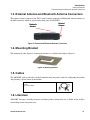
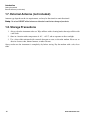
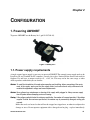
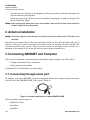
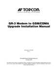
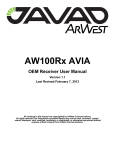
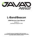
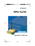
AW900BT User Manual Version 1.2 Last Revised April 12, 2013 All contents in this manual are copyrighted by ArWest Communications. All rights reserved. The information contained herein may not be used, accessed, copied, stored, displayed, sold, modified, published, or distributed, or otherwise reproduced without express written consent from ArWest Communications. www.arwestcom.com TABLE OF CONTENTS Preface . . . . . . . . . . . . . . . . . . . . . . . . . . . . . . . . . . . . . . . . . . . . . . . . . . . . . . . . .7 Terms and Conditions. . . . . . . . . . . . . . . . . . . . . . . . . . . . . . . . . . . . . . . . . . . . . . . . . . . . . . . . 7 Regulatory Information . . . . . . . . . . . . . . . . . . . . . . . . . . . . . . . . . . . . . . . . . . . . . . . . . . . . . . 9 Manual Conventions. . . . . . . . . . . . . . . . . . . . . . . . . . . . . . . . . . . . . . . . . . . . . . . . . . . . . . . . 10 Screen Captures . . . . . . . . . . . . . . . . . . . . . . . . . . . . . . . . . . . . . . . . . . . . . . . . . . . . . . . . . . . 10 Technical Assistance . . . . . . . . . . . . . . . . . . . . . . . . . . . . . . . . . . . . . . . . . . . . . . . . . . . . . . . 10 Chapter 1. Introduction . . . . . . . . . . . . . . . . . . . . . . . . . . . . . . . . . . . . . . . . . . .11 1. Getting Acquainted. . . . . . . . . . . . . . . . . . . . . . . . . . . . . . . . . . . . . . . . . . . . . . . . . . . . . . . 12 1.1. LEDs. . . . . . . . . . . . . . . . . . . . . . . . . . . . . . . . . . . . . . . . . . . . . . . . . . . . . . . . . . . . . 12 1.2. Data and Power Port. . . . . . . . . . . . . . . . . . . . . . . . . . . . . . . . . . . . . . . . . . . . . . . . . 12 1.3. External Antenna and Bluetooth Antenna Connectors. . . . . . . . . . . . . . . . . . . . . . . 13 1.4. Mounting Bracket. . . . . . . . . . . . . . . . . . . . . . . . . . . . . . . . . . . . . . . . . . . . . . . . . . . 13 1.5. Cables . . . . . . . . . . . . . . . . . . . . . . . . . . . . . . . . . . . . . . . . . . . . . . . . . . . . . . . . . . . . 13 1.6. Literature . . . . . . . . . . . . . . . . . . . . . . . . . . . . . . . . . . . . . . . . . . . . . . . . . . . . . . . . . 13 1.7. External Antenna (not included) . . . . . . . . . . . . . . . . . . . . . . . . . . . . . . . . . . . . . . . 14 1.8. Storage Precautions . . . . . . . . . . . . . . . . . . . . . . . . . . . . . . . . . . . . . . . . . . . . . . . . . 14 Chapter 2. Configuration. . . . . . . . . . . . . . . . . . . . . . . . . . . . . . . . . . . . . . . . . .15 1. Powering AW900BT . . . . . . . . . . . . . . . . . . . . . . . . . . . . . . . . . . . . . . . . . . . . . . . . . . . . . 15 1.1. Power supply requirements . . . . . . . . . . . . . . . . . . . . . . . . . . . . . . . . . . . . . . . . . . . 15 2. Antenna Installation . . . . . . . . . . . . . . . . . . . . . . . . . . . . . . . . . . . . . . . . . . . . . . . . . . . . . . 16 3. Connecting AW900BT and Computer . . . . . . . . . . . . . . . . . . . . . . . . . . . . . . . . . . . . . . . . 16 3.1. Connecting through serial port . . . . . . . . . . . . . . . . . . . . . . . . . . . . . . . . . . . . . . . . . 16 3.2. Connecting through USB port . . . . . . . . . . . . . . . . . . . . . . . . . . . . . . . . . . . . . . . . . 17 3.3. Connecting through Bluetooth® . . . . . . . . . . . . . . . . . . . . . . . . . . . . . . . . . . . . . . . 17 4. Configuring AW900BT . . . . . . . . . . . . . . . . . . . . . . . . . . . . . . . . . . . . . . . . . . . . . . . . . . . 18 4.1. Checking firmware version . . . . . . . . . . . . . . . . . . . . . . . . . . . . . . . . . . . . . . . . . . . 19 4.2. New Firmware Downloading . . . . . . . . . . . . . . . . . . . . . . . . . . . . . . . . . . . . . . . . . . 20 Chapter 3. Command Line Interface . . . . . . . . . . . . . . . . . . . . . . . . . . . . . . . .21 3.1. Command Line Interface Convention . . . . . . . . . . . . . . . . . . . . . . . . . . . . . . . . . . . . . . . 21 3.1.1. Software Switching to Maintenance Mode . . . . . . . . . . . . . . . . . . . . . . . . . . . . . . 22 3.1.2. Switching to Data Mode . . . . . . . . . . . . . . . . . . . . . . . . . . . . . . . . . . . . . . . . . . . . 22 www.arwestcom.com 3 3.1.3. Software Switching to Data Route Mode. . . . . . . . . . . . . . . . . . . . . . . . . . . . . . . 23 3.1.4. Return from Data Route Mode . . . . . . . . . . . . . . . . . . . . . . . . . . . . . . . . . . . . . . . 23 3.2. Modem Commands. . . . . . . . . . . . . . . . . . . . . . . . . . . . . . . . . . . . . . . . . . . . . . . . . . . . . 3.2.1. LINK. . . . . . . . . . . . . . . . . . . . . . . . . . . . . . . . . . . . . . . . . . . . . . . . . . . . . . . . . . . 3.2.2. MAP F . . . . . . . . . . . . . . . . . . . . . . . . . . . . . . . . . . . . . . . . . . . . . . . . . . . . . . . . . 3.2.3. MAP FTX. . . . . . . . . . . . . . . . . . . . . . . . . . . . . . . . . . . . . . . . . . . . . . . . . . . . . . . 3.2.4. MAP Fddddddddd . . . . . . . . . . . . . . . . . . . . . . . . . . . . . . . . . . . . . . . . . . . . . . . . 3.2.5. MAP FTX ddddddddd . . . . . . . . . . . . . . . . . . . . . . . . . . . . . . . . . . . . . . . . . . . . . 3.2.6. RGN . . . . . . . . . . . . . . . . . . . . . . . . . . . . . . . . . . . . . . . . . . . . . . . . . . . . . . . . . . . 3.2.7. TRFC . . . . . . . . . . . . . . . . . . . . . . . . . . . . . . . . . . . . . . . . . . . . . . . . . . . . . . . . . . 3.2.8. LSRT . . . . . . . . . . . . . . . . . . . . . . . . . . . . . . . . . . . . . . . . . . . . . . . . . . . . . . . . . . 3.2.9. DCRC . . . . . . . . . . . . . . . . . . . . . . . . . . . . . . . . . . . . . . . . . . . . . . . . . . . . . . . . . . 3.2.10. DLNG . . . . . . . . . . . . . . . . . . . . . . . . . . . . . . . . . . . . . . . . . . . . . . . . . . . . . . . . . 3.2.11. DSRV . . . . . . . . . . . . . . . . . . . . . . . . . . . . . . . . . . . . . . . . . . . . . . . . . . . . . . . . . 3.2.12. LBT. . . . . . . . . . . . . . . . . . . . . . . . . . . . . . . . . . . . . . . . . . . . . . . . . . . . . . . . . . . 3.2.13. WHT . . . . . . . . . . . . . . . . . . . . . . . . . . . . . . . . . . . . . . . . . . . . . . . . . . . . . . . . . . 3.2.14. SRC. . . . . . . . . . . . . . . . . . . . . . . . . . . . . . . . . . . . . . . . . . . . . . . . . . . . . . . . . . . 3.2.15. DST. . . . . . . . . . . . . . . . . . . . . . . . . . . . . . . . . . . . . . . . . . . . . . . . . . . . . . . . . . . 3.2.16. KNW. . . . . . . . . . . . . . . . . . . . . . . . . . . . . . . . . . . . . . . . . . . . . . . . . . . . . . . . . . 23 23 24 24 24 24 24 25 25 26 26 26 26 27 27 27 27 3.3. Special Commands . . . . . . . . . . . . . . . . . . . . . . . . . . . . . . . . . . . . . . . . . . . . . . . . . . . . . 3.3.1. BOOT . . . . . . . . . . . . . . . . . . . . . . . . . . . . . . . . . . . . . . . . . . . . . . . . . . . . . . . . . . 3.3.2. HELP . . . . . . . . . . . . . . . . . . . . . . . . . . . . . . . . . . . . . . . . . . . . . . . . . . . . . . . . . . 3.3.3. SAVE . . . . . . . . . . . . . . . . . . . . . . . . . . . . . . . . . . . . . . . . . . . . . . . . . . . . . . . . . . 3.3.4. CFG2DFLT . . . . . . . . . . . . . . . . . . . . . . . . . . . . . . . . . . . . . . . . . . . . . . . . . . . . . 3.3.5. XMOD IMAGE . . . . . . . . . . . . . . . . . . . . . . . . . . . . . . . . . . . . . . . . . . . . . . . . . . 28 28 28 28 29 29 3.4. Identification and Diagnostics Commands . . . . . . . . . . . . . . . . . . . . . . . . . . . . . . . . . . . 3.4.1. INFO. . . . . . . . . . . . . . . . . . . . . . . . . . . . . . . . . . . . . . . . . . . . . . . . . . . . . . . . . . . 3.4.2. STATE . . . . . . . . . . . . . . . . . . . . . . . . . . . . . . . . . . . . . . . . . . . . . . . . . . . . . . . . . 3.4.3. IC . . . . . . . . . . . . . . . . . . . . . . . . . . . . . . . . . . . . . . . . . . . . . . . . . . . . . . . . . . . . . 3.4.4. FCC ID . . . . . . . . . . . . . . . . . . . . . . . . . . . . . . . . . . . . . . . . . . . . . . . . . . . . . . . . . 3.4.5. GTX . . . . . . . . . . . . . . . . . . . . . . . . . . . . . . . . . . . . . . . . . . . . . . . . . . . . . . . . . . . 3.4.6. RSS . . . . . . . . . . . . . . . . . . . . . . . . . . . . . . . . . . . . . . . . . . . . . . . . . . . . . . . . . . . . 3.4.7. RSSI . . . . . . . . . . . . . . . . . . . . . . . . . . . . . . . . . . . . . . . . . . . . . . . . . . . . . . . . . . . 3.4.8. RSSM . . . . . . . . . . . . . . . . . . . . . . . . . . . . . . . . . . . . . . . . . . . . . . . . . . . . . . . . . . 3.4.9. RSSC . . . . . . . . . . . . . . . . . . . . . . . . . . . . . . . . . . . . . . . . . . . . . . . . . . . . . . . . . . 3.4.10. RNSS . . . . . . . . . . . . . . . . . . . . . . . . . . . . . . . . . . . . . . . . . . . . . . . . . . . . . . . . . 3.4.11. NSCN . . . . . . . . . . . . . . . . . . . . . . . . . . . . . . . . . . . . . . . . . . . . . . . . . . . . . . . . . 3.4.12. SCAN . . . . . . . . . . . . . . . . . . . . . . . . . . . . . . . . . . . . . . . . . . . . . . . . . . . . . . . . . 3.4.13. SCNS . . . . . . . . . . . . . . . . . . . . . . . . . . . . . . . . . . . . . . . . . . . . . . . . . . . . . . . . . 29 29 29 30 30 30 30 31 31 31 31 31 31 32 3.5. Modem protection from interference . . . . . . . . . . . . . . . . . . . . . . . . . . . . . . . . . . . . . . . 32 3.5.1. NLST . . . . . . . . . . . . . . . . . . . . . . . . . . . . . . . . . . . . . . . . . . . . . . . . . . . . . . . . . . 32 3.5.2. NADD. . . . . . . . . . . . . . . . . . . . . . . . . . . . . . . . . . . . . . . . . . . . . . . . . . . . . . . . . . 32 4 www.arwestcom.com 3.5.3. NAPL. . . . . . . . . . . . . . . . . . . . . . . . . . . . . . . . . . . . . . . . . . . . . . . . . . . . . . . . . . . 32 3.5.4. NDEL . . . . . . . . . . . . . . . . . . . . . . . . . . . . . . . . . . . . . . . . . . . . . . . . . . . . . . . . . . 32 3.6. Data Route Mode Commands . . . . . . . . . . . . . . . . . . . . . . . . . . . . . . . . . . . . . . . . . . . . . 33 3.6.1. JLDEV. . . . . . . . . . . . . . . . . . . . . . . . . . . . . . . . . . . . . . . . . . . . . . . . . . . . . . . . . . 33 3.6.2. JLBT . . . . . . . . . . . . . . . . . . . . . . . . . . . . . . . . . . . . . . . . . . . . . . . . . . . . . . . . . . . 34 3.6.3. JLROUTE . . . . . . . . . . . . . . . . . . . . . . . . . . . . . . . . . . . . . . . . . . . . . . . . . . . . . . . 34 3.6.4. JLINFO . . . . . . . . . . . . . . . . . . . . . . . . . . . . . . . . . . . . . . . . . . . . . . . . . . . . . . . . . 35 3.6.5. JLSTATE. . . . . . . . . . . . . . . . . . . . . . . . . . . . . . . . . . . . . . . . . . . . . . . . . . . . . . . . 35 3.6.6. XMOD IMAGE. . . . . . . . . . . . . . . . . . . . . . . . . . . . . . . . . . . . . . . . . . . . . . . . . . . 36 3.6.7. MCU BOOT . . . . . . . . . . . . . . . . . . . . . . . . . . . . . . . . . . . . . . . . . . . . . . . . . . . . . 36 3.6.8. JLDEV SLEEP ON . . . . . . . . . . . . . . . . . . . . . . . . . . . . . . . . . . . . . . . . . . . . . . . . 36 Appendix A. Specifications. . . . . . . . . . . . . . . . . . . . . . . . . . . . . . . . . . . . . . . .37 A.1. Technical Specifications . . . . . . . . . . . . . . . . . . . . . . . . . . . . . . . . . . . . . . . . . . . . . . . . . 37 A.1.1. Radio Receiver . . . . . . . . . . . . . . . . . . . . . . . . . . . . . . . . . . . . . . . . . . . . . . . . . . . 37 A.1.2. Radio Transmitter. . . . . . . . . . . . . . . . . . . . . . . . . . . . . . . . . . . . . . . . . . . . . . . . . 38 A.1.3. Modem . . . . . . . . . . . . . . . . . . . . . . . . . . . . . . . . . . . . . . . . . . . . . . . . . . . . . . . . . 38 A.1.4. Environmental Specifications. . . . . . . . . . . . . . . . . . . . . . . . . . . . . . . . . . . . . . . . 38 A.1.5. Compliance. . . . . . . . . . . . . . . . . . . . . . . . . . . . . . . . . . . . . . . . . . . . . . . . . . . . . . 39 A.2. Connector Specifications . . . . . . . . . . . . . . . . . . . . . . . . . . . . . . . . . . . . . . . . . . . . . . . . 39 A.2.1. DB15 Connector. . . . . . . . . . . . . . . . . . . . . . . . . . . . . . . . . . . . . . . . . . . . . . . . . . 39 A.2.2. External Antenna RF Connector . . . . . . . . . . . . . . . . . . . . . . . . . . . . . . . . . . . . . 40 Appendix B. Safety Warnings. . . . . . . . . . . . . . . . . . . . . . . . . . . . . . . . . . . . . .41 B.1. General Warnings . . . . . . . . . . . . . . . . . . . . . . . . . . . . . . . . . . . . . . . . . . . . . . . . . . . . . . 42 Appendix C. Warranty Terms . . . . . . . . . . . . . . . . . . . . . . . . . . . . . . . . . . . . . .43 www.arwestcom.com 5 6 www.arwestcom.com PREFACE Thank you for purchasing this product. The materials available in this Manual (the “Manual”) have been prepared by ArWest Communications, Corp. (“ArWest”) for owners of ArWest products. It is designed to assist owners with the use of AW900BT and its use is subject to these terms and conditions (the “Terms and Conditions”). Note: Please read these Terms and Conditions carefully. Terms and Conditions USE – ArWest modems are designed to be used by a professional. The user is expected to have a good knowledge and understanding of the user and safety instructions before operating, inspecting or adjusting. COPYRIGHT – All information contained in this Manual is the intellectual property of, and copyrighted material of ArWest. All rights are reserved. You may not use, access, copy, store, display, create derivative works of, sell, modify, publish, distribute, or allow any third party access to, any graphics, content, information or data in this Manual without ArWest’ express written consent and may only use such information for the care and operation of your AW900BT. The information and data in this Manual are a valuable asset of ArWest and are developed by the expenditure of considerable work, time and money, and are the result of original selection, coordination and arrangement by ArWest. TRADEMARKS – AW900BT™, TRIUMPH-1™, ModemVU™, ArWest® are trademarks or registered trademarks of ArWest Communications Corp. Windows ® is a registered trademark of Microsoft Corporation; Bluetooth® word mark is owned by the Bluetooth SIG, Inc. Product and company names mentioned herein may be trademarks of their respective owners. DISCLAIMER OF WARRANTY – EXCEPT FOR ANY WARRANTIES IN THIS MANUAL OR A WARRANTY CARD ACCOMPANYING THE PRODUCT, THIS MANUAL AND THE AW900BT MODEM ARE PROVIDED “AS-IS.” THERE ARE NO OTHER WARRANTIES. ARWEST DISCLAIMS ANY IMPLIED WARRANTY OF MERCHANTABILITY OR FITNESS FOR ANY PARTICULAR USE OR PURPOSE. ARWEST AND ITS DISTRIBUTORS SHALL NOT BE LIABLE FOR TECHNICAL OR EDITORIAL ERRORS OR OMISSIONS CONTAINED HEREIN; NOR FOR INCIDENTAL OR CONSEQUENTIAL DAMAGES RESULTING FROM THE FURNISHING, PERFORMANCE OR USE OF THIS MATERIAL OR THE AW900BT MODEM. SUCH DISCLAIMED DAMAGES INCLUDE BUT ARE NOT LIMITED TO LOSS OF TIME, LOSS OR DESTRUCTION OF DATA, LOSS OF PROFIT, SAVINGS OR REVENUE, OR LOSS OF THE PRODUCT'S USE. IN ADDITION, ARWEST IS NOT RESPONSIBLE OR LIABLE FOR DAMAGES OR COSTS INCURRED IN CONNECTION WITH OBTAINING SUBSTITUTE PRODUCTS OR SOFTWARE, CLAIMS BY OTHERS, INCONVENIENCE, OR ANY OTHER COSTS. IN ANY www.arwestcom.com 7 Preface Terms and Conditions EVENT, ARWEST SHALL HAVE NO LIABILITY FOR DAMAGES OR OTHERWISE TO YOU OR ANY OTHER PERSON OR ENTITY IN EXCESS OF THE PURCHASE PRICE FOR AW900BT. LICENSE AGREEMENT – Use of any computer programs or software supplied by ARWEST or downloaded from a ArWest website (the “Software”) in connection with AW900BT constitutes acceptance of these Terms and Conditions in this Manual and an agreement to abide by these Terms and Conditions. The user is granted a personal, non-exclusive, non-transferable license to use such Software under the terms stated herein and in any case only with a single AW900BT or single computer. You may not assign or transfer the Software or this license without the express written consent of ArWest. This license is effective until terminated. You may terminate the license at any time by destroying the Software and Manual. ArWest may terminate the license if you fail to comply with any of the Terms or Conditions. You agree to destroy the Software and manual upon termination of your use of AW900BT. All ownership, copyright and other intellectual property rights in and to the Software belong to ArWest. If these license terms are not acceptable, return any unused software and manual. CONFIDENTIALITY – This Manual, its contents and the Software (collectively, the “Confidential Information”) are the confidential and proprietary information of ArWest. You agree to treat ArWest' Confidential Information with a degree of care no less stringent that the degree of care you would use in safeguarding your own most valuable trade secrets. Nothing in this paragraph shall restrict you from disclosing Confidential Information to your employees as may be necessary or appropriate to operate or care for AW900BT. Such employees must also keep the Confidentiality Information confidential. In the event you become legally compelled to disclose any of the Confidential Information, you shall give ArWest immediate notice so that it may seek a protective order or other appropriate remedy. WEBSITE; OTHER STATEMENTS – No statement contained at the ArWest website (or any other website) or in any other advertisements or ArWest literature or made by an employee or independent contractor of ArWest modifies these Terms and Conditions (including the Software license, warranty and limitation of liability). SAFETY – Improper use of AW900BT can lead to injury to persons or property and/or malfunction of the product. The AW900BT modem should only be repaired by authorized ArWest warranty service centers. Users should review and heed the safety warnings in Appendix C. MISCELLANEOUS – The above Terms and Conditions may be amended, modified, superseded, or canceled, at any time by ArWest. The above Terms and Conditions will be governed by, and construed in accordance with, the laws of the State of California, without reference to conflict of laws. 8 www.arwestcom.com Preface Regulatory Information FCC Class A Compliance Regulatory Information FCC Class A Compliance This equipment has been tested and found to comply with the limits for a Class A digital device, pursuant to part 15 of the FCC Rules. These limits are designed to provide reasonable protection against harmful interference when the equipment is operated in a commercial environment. This equipment generates, uses, and can radiate radio frequency energy and, if not installed and used in accordance with the instruction manual, may cause harmful interference to radio communications. Operation of this equipment in a residential area is likely to cause harmful interference in which case the user will be required to correct the interference at his own expense. CAUTION: Any changes or modifications to the equipment not expressly approved by the party responsible for compliance could void your authority to operate such equipment. Canadian Emissions Labeling Requirements This Class A digital apparatus meets all requirements of the Canadian Interference-Causing Equipment Regulations. Cet appareil numérique de la classe A respecte toutes les exigences du Réglement sur le matériel brouilleur du Canada. Industry Canada The term “IC:” before the equipment certification number only signifies that the Industry Canada technical specifications were met. WEEE Directive The following information is for EU-member states only: The use of the symbol indicates that this product may not be treated as household waste. By ensuring this product is disposed of correctly, you will help prevent potential negative consequences for the environment and human health, which could otherwise be caused by inappropriate waste handling of this product. For more detailed information about the take-back and recycling of this product, please contact your supplier where you purchased the product or consult. www.arwestcom.com 9 Preface Manual Conventions WEEE Directive Manual Conventions This manual uses the following conventions: Example Description FileExit Click the File menu and click Exit Link Space This format represents titles of dialog windows/boxes, names of menu options, identifies program interface objects, such as checkboxes, edit boxes, radio buttons, etc. Temp This format is used to enter various string information (e.g., file and directory names) as well as operator commands. Screen Captures This manual includes sample screen captures. Your actual screen can look slightly different from the sample screen due to the modem you have connected, operating system used and settings you have specified. This is normal and not a cause for concern. Technical Assistance If you have a problem and cannot find the information you need in the product documentation, contact your local dealer. Alternatively, request technical support using the [email protected]. 10 www.arwestcom.com Chapter 1 INTRODUCTION External extra rugged digital high power UHF radio transceiver is designed as universal license-free modem. It uses 902-928 MHz ISM (industrial, scientific and medical) license free USA/Australia band frequency hopping transmission techniques for excellent reliability in noisy plant environments and European CEPT license free 868-870 MHz band, allocated for narrow band telemetry, alarms and data transfer applications. Figure 1. AW900BT The AW900BT is a wireless system, based on FH915 – Spread Spectrum Radio Transceiver. The Digital Data is delivered to/from the FH915 Radio Transceiver through the Serial (RS232) connection, through USB- to-Serial adapter or through the Bluetooth module. The modem status is indicated by LEDs. The AW900BT radio transceiver provides a high-speed Point-to-Point and Point-to-Multipoint wireless data transfer at up to 64.0 kbps. AW900BT supports GMSK modulation technique, which allows the user to achieve the highest data speed. It also includes a forward error correction, data packets doubling technique and data scrambling, which improve the functioning of the radio modem with frequency hopping under interference. The output power is programmable up to 1 W. The sophisticated features of AW900BT include user selectable frequency hopping sequences and transmit output power level, low power consumption sleep modes and plug-and-play installation for remote terminals. The firmware of the AW900BT radio transceiver resides in a flash memory. The updating of the radio modem programs is entirely software-based. The flash memory is reprogrammable through an RS232 interface, USB, or Bluetooth. The unit’s user settings can be changed through the built-in Command Line interface (CLI) or through the supporting software ModemVU - Windows based Unit Configuration and Maintenance Software Application running on a IBM PC compatible computer and connecting to the device over RS-232 interface or USB. www.arwestcom.com 11 Introduction Getting Acquainted LEDs The diagnostic feature of the FH915 system provides the information to monitor and maintain user’s communications link. The output transmit power, received signal strength (RSSI) and data decode performance are transmitted online without application interruption. The product is designed for maximum performance and reliability even in the harshest environments. 1. Getting Acquainted The AW900BT is a rugged and very powerful external radio transceiver 146 mm wide 75 mm deep 44 mm high, weighs 488 g. 1.1. LEDs External LED's (see Figure 2) are used for Link and Line status indication: Position LED Name Color Description 1 PWR Green Active if power connected to modem 2 RX Green Active if modem receives data 3 TX Green Active if modem transmits data 4 BT Blue Active if modem receives or transmits data over Bluetooth 1.2. Data and Power Port The AW900BT data and power port is placed on the front of the unit (Figure 2). Data and power port LEDs Figure 2. AW900BT front side Through the DB15 port the AW900BT can be connected to PC with Accessory Data-Ser-Pwr Cable, DB9/DB15/SAE (6ft/1.8m) p/n 14-578108-02 and can be powered. See “Powering AW900BT” on page 13 for detailed information. 12 www.arwestcom.com Introduction Getting Acquainted External Antenna and Bluetooth Antenna Connectors 1.3. External Antenna and Bluetooth Antenna Connectors The external antenna connects to the TNC external antenna connector and Bluetooth antenna connects to the SMA connector which are placed on the back panel of AW900BT. External Bluetooth Antenna Antenna Figure 3. External and Bluetooth Antenna Connectors 1.4. Mounting Bracket The mounting bracket (Figure 4) connects the modem to a standard pole/adapter (Figure 4). Figure 4. Mounting Bracket 1.5. Cables The AW900BT package includes standard communication and power cables for configuring the modem and providing a power source to the modem. Accessory Data-Ser-Pwr Cable, ODU-7/DB15/SAE (1,8m) p/n 14-578110-02 1.6. Literature AW900BT literature, including manuals and other product information are available on the ArWest website http://www.arwestcom.com. www.arwestcom.com 13 Introduction Getting Acquainted External Antenna (not included) 1.7. External Antenna (not included) Antenna type depends on the site requirements, and may be directional or omni-directional. Warning: Do not use AW900BT without antenna our attenuator to avoid serious damage of your device. 1.8. Storage Precautions 1. Always clean the instrument after use. Wipe off dust with a cleaning brush, then wipe off dirt with a soft cloth. 2. Store in a location with a temperature of -40°... +85°C, and no exposure to direct sunlight. 3. Use a clean cloth, moistened with a neutral detergent or water, to clean the modem. Never use an abrasive cleaner, ether, thinner benzene, or other solvents. Always make sure the instrument is completely dry before storing. Dry the modem with a soft, clean cloth. 14 www.arwestcom.com Chapter 2 CONFIGURATION 1. Powering AW900BT To power AW900BT use the Battery kit 1 (p/n 99-587300-10). Figure 1. Battery Kit 1 1.1. Power supply requirements A single external power supply is necessary to operate AW900BT. The external power supply needs to be Listed for US and Certified for EU countries, it needs also to be a Limited Power Source and rated for Outdoor Use and have an output rated for +9... +36V, 4A. This may not be the same range as other ArWest products with which you are familiar. CAUTION: To avoid the introduction of hazards when operating and installing, before connecting of the equipment to the supply, make sure that the supply meets local and national safety ordinances and matches the equipment’s voltage and current requirements. CAUTION: Never attempt any maintenance or cleaning of the supply while plugged in. Always remove supply from AC power before attempting service or cleaning. Warning: If the voltage supplied is below the minimum specification, the modem will suspend operation. If the voltage supplied is above the maximum specification, the modem may be permanently damaged, voiding your warranty. Make sure cords are located so that will not be stepped on, tripped over, or otherwise subjected to damage or stress. Do not operate equipment with a damaged cord or plug – replace immediately. www.arwestcom.com 15 Configuration Antenna Installation Connecting through serial port To reduce the risk of damage to the equipment, pull by the plug body rather than the output cord when disconnecting the equipment. Do not operate the supply if it has received a sharp blow, been dropped, or otherwise damaged. Do not disassemble the supply. Warning: Before connecting the external power source and the modem, make sure that the power source matches the modem’s voltage and current requirements. 2. Antenna Installation Warning: To avoid the equipment serious damage, do not switch the modem to transmit mode if RF antenna is not connected! Select the type of antenna that best fits your application and the one that offers the highest dB gain. In addition, setup your system in the highest possible location to minimize obstacles between the transmitting and receiving systems. Always place the antenna on the highest point available. At a minimum, set the antenna to at least ten feet above the terrain using an antenna mast. 3. Connecting AW900BT and Computer Once you have established a connection between the modem and the computer, you will be able to: • Configure the modem and its components • Send commands to the modem Use ModemVU to load new firmware to the modem. 3.1. Connecting through serial port To configure, or maintain AW900BT, you need to connect the modem and a computer using an Accessory Data-Ser-Pwr Cable, DB9/DB15/SAE (1,8m), p/n14-578108-02. Figure 2. Accessory Data-Ser-Pwr Cables DB9/DB15/SAE Default parameters for Serial port are: • Baud Rate:115200 • Data Bits:8 • Stop Bits:1 16 www.arwestcom.com Configuration Connecting AW900BT and Computer Connecting through USB port • Parity:None • Flow control:RTS/CTS 3.2. Connecting through USB port Make sure the computer has special USB driver installed (available from www.arwestcom.com) before continuing. To configure, or maintain AW900BT using USB port, you need to connect the modem and a computer using special cable Access Data-Ser Cable, USB/DB15/SAE (1,8m) (p/n 14-578123-02). Figure 3. Cable p/n 14-578123-01 1. Download the zip-archive with USB driver from www.arwestcom.com; 2. Extract the archive to the new empty folder; 3. Connect the USB port of the computer to the data port of the modem at the switched off power supply by using of a cable. 4. Turn on your computer. 5. Power AW900BT. 6. Widows will detect USB driver automatically. Otherwise it will ask to specify driver location. Select the folder with extracted file. Default parameters for USB Bridge port are: • • • • • Baud Rate:115200 Data Bits:8 Stop Bits:1 Parity:None Flow control:RTS/CTS 3.3. Connecting through Bluetooth® Note: Do not forget to attach the Bluetooth® antenna to Bluetooth antenna connector on the back panel of the modem. The AW900BT modem contains Bluetooth® wireless technology that allows synchronization between the modem and any other external device that supports Bluetooth® wireless technology; for example, an IPAQ, or a computer with USB-to-Bluetooth® adapter or PCMCA-to-Bluetooth® adapter installed, etc. AW900BT and external device connection procedure varies slightly depending on the type of external device used. In general, the connection procedure is as follows: www.arwestcom.com 17 Configuration Configuring AW900BT Connecting through Bluetooth® Note: Refer to your Bluetooth ® -enabled external device documentation for more detailed connection information. 1. Turn on a Bluetooth®-enabled external device and your receiver. The default external device mode is Master; the modem’s Bluetooth® module mode is Slave. 2. Instruct the external device (Master) to search for the modem (Slave). 3. Once the Master device detects the modem, use the procedure described in the external device’s documentation to connect it with the modem. 4. Configuring AW900BT 1. Connect the computer and AW900BT, as described in“Connecting AW900BT and Computer” on page 16. 2. Turn on the AW900BT. 3. Start ModemVU. Main window appears (Figure 4). Choose AW900BT modem and click OK. Then select the COM port the modem is connected to, and click Connect.: Figure 4. Main window 4. Once the connection is established the window with General, Interface, BT, and Identification subtabs will appear: 18 www.arwestcom.com Configuration Configuring AW900BT Checking firmware version Figure 5. General tab 5. Set the needed parameters. To save the changes click Apply button. 4.1. Checking firmware version Identification tab shows versions of AW900BT components: Figure 6. Identification tab This tab lists important information about the hardware accessories and software properties. This list includes the following, which you will need if you contact ArWest Communications or your dealer: www.arwestcom.com 19 Configuration Configuring AW900BT New Firmware Downloading • • • • • • Unit Type Unit Name Modem Serial Number Firmware Version Hardware Version BootLoader Version 4.2. New Firmware Downloading 1. To download new firmware use Tools tab. Figure 7. Tools tab 2. Click Download FW modem, select the file with the new modem firmware and click OK. 3. Click Download FW MCU, select the file with the new MCU firmware and click OK. 4. Use the latest firmware version, available for download from the ArWest website www.arwestcom.com, to ensure your modem has the most recent updates. 20 www.arwestcom.com Chapter 3 COMMAND LINE INTERFACE The built-in user-friendly Command Line Interface (CLI) allows user to perform a full configuration of the unit and read the statistics and alarm status. It is the most powerful tool to configure the unit. It makes changes to all possible settings that system will not be able to determine automatically. Note: The unit’s configuration that is set or modified through the CLI will be lost after unit’s reboot, unless the saving operation is used to store a new setting in the unit’s configuration file. The CLI commands also provide filing operations, which include: • Downloading Software Images • Saving into the configuration files the configuration parameters modified through the CLI. 3.1. Command Line Interface Convention The following convention is implemented in FH915 Command Line Interface (CLI): • The Carriage Return/Line Feed (CR/LF, 0x0D/0x0A) is a command delimiter. Command delimiters CR or LF or CR+LF are valid. Preferable delimiter - LF. • The Carriage Return/Line Feed (CR/LF, 0x0D/0x0A) is a reply delimiter followed by the “CLI>” prompt if Echo option is On. • The Carriage Return/Line Feed (CR/LF, 0x0D/0x0A) is a reply delimiter if Echo option is Off (default option). • The 2-digit number followed by “@” in the unit’s reply indicates the error code (refer to Table 31 for description), if Echo Off is selected. • A successfully performed command is replied by @00 code, if Echo Off is selected. • A command with the certain [Parameter Name] and blank [Parameter List] displays the current settings for a given parameter. • To set the mode ordered by CLI commands as permanent User Setting (the setting automatically selected for the boot-up unit) the SAVE command must be asserted. • [/?] orders to show the help information for the given command. • Commands are not key sensitive; small, none capital characters can be used to enter CLI commands. Table 3-1. Command Line Interface Error Codes Error Code Short Description 0x01 Command Syntax Error. 0x02 The parameter has a format error. www.arwestcom.com 21 Command Line Interface Command Line Interface Convention Software Switching to Maintenance Mode Error Code Short Description 0x03 The parameter is out of allowed range. 0x04 The command is not valid for specific radio model. 0x05 Unspecified Error 3.1.1. Software Switching to Maintenance Mode To switch to Maintenance mode the special byte-sequences with special meanings are used: • Escape-Sequence: “+++” with 20 ms guard time before and after the command characters • Escape-Acknowledge: “@00<CR><LF>”. Happy Flow 1. In data-mode the unit starts looking for the Escape-sequence if there is no data from DTE for more than 20 ms (Start Guard Time). 2. If the unit detects the Escape-Sequence: • The transmitter continues sending over the air the data received from DTE before EscapeSequence; • The Receiver immediately stops forwarding to DTE the data received over the air and buffers it instead. 3. The radio unit waits for 20 ms and then sends Escape-Acknowledge to DTE if there is no data from DTE during 20 ms of Stop Guard Time. 4. The unit goes to Maintenance mode and discards Escape-Sequence from input buffer. The modem is immediately ready to receive commands. At the same time it continues buffering the data received over the air since step 2. Escape-Sequence in Data During its waiting in step 3, the unit receives data from DTE: • The unit sends buffered Escape-Sequence from DTE to the air; • The unit sends all buffered data received from the air since step 2 to DTE and stays in data-mode (i.e. transmits data received from DTE over the air – including the just received, unexpected, data and forwards data received over the air to DTE.) 3.1.2. Switching to Data Mode • DTE sends the CLI command “DATAMODE<CR>” or „DATAMODE<LF>” to the unit. Note: Command “DATAMODE<CR><LF>” will be accepted as command “DATAMODE<CR>” and Data Byte=0x0A. • Unit immediately goes to datamode, so that the DTE can start sending data. 22 www.arwestcom.com Command Line Interface Modem Commands Software Switching to Data Route Mode • The data received over the air goes from buffer to DTE. If you need clear the buffer before going to datamode use the CLI command “DATAMOD<LF>”. • If no valid CLI commands received from DTE within 1 minute, the unit will automatically switch back to data-mode. Note: The data received over the air could be lost due to Rx buffer overflow if the unit stays in Maintenance mode long time. 3.1.3. Software Switching to Data Route Mode To switch to Data Route Mode the special byte-sequences with special meanings are used: • Escape-Sequence: “####” with 20 ms guard time before and after the command characters; • Escape-Acknowledge: “@00<CR><LF>”. 3.1.4. Return from Data Route Mode • Command “MCU CLI OFF<CR>” returns modem from Data Route Mode. • Unit immediately goes to datamode, so that the DTE can start sending data. 3.2. Modem Commands 3.2.1. LINK The LINK command is responsible for configuring radio’s operation mode. LINK [Parameter Name] [Parameters List] [/?] LINK commands are as common so specific for two bands: 902-928 MHz band and 868-870 MHz band: Parameter Name Parameter List FEC 0 – Disable Forward Error Correction (a default setting) 1 – Enable Forward Error Correction FHOP (0-9) - Frequency Hoping Pattern numbers for USA; (10-19) - Frequency Hoping Pattern numbers for Australia; For EU parameter FHOP not applied MOD 5 - GMSK PWRB (15 – 30) – RF output Power in dBm SCRAM 0 – No Scrambling 1 - Scrambling with Pseudo-Random Sequence Generator (a default setting) 2 - Scrambling with User defined SEED. SCR 001,...,511 - User defined decimal SEED SPACE 0 - 25.0 kHz Channel Spacing (a default setting) 1 - 12.5 kHz Channel Spacing 2 - 6.25 kHz Channel Spacing www.arwestcom.com 23 Command Line Interface Modem Commands MAP F Parameter Name Parameter List PMP 0 – “Any transmits, any receives”. At the receiver side neither the source nor the recipient is validated. If parameter PMP =0, then its value is not displayed in a “link\n” response. (a default setting) 1 – “Any transmits to me only”. The receiver compares the received code DST with its code SRC. If the received code DST coincides with the code SRC of the receiver, the received data are distributed to the port. If the received code DST is not coincide with the code SRC of the receiver, the received data to the port are not provided. 2 – “Certified Base transmits to any”. The receiver compares the received code SRC and code KNW. If the received code SRC coincides with the code KNW, stored in the configuration file of the receiver, the received data are distributed to the port. If the received code SRC is not coincide with the code KNW, then the received data to the port are not provided. 3 – “Certified Base transmits to me only”. The receiver compares the received codes: code DST with its code SRC and the code SRC with the code KNW. If these codes match the received data are distributed to the port. REP 0 – Repeater mode is disabled. If parameter REP =0, then its value is not displayed in a “link\n” response. (a default setting) 1 - Repeater mode is enabled. Modem retransmits the received data. The LINK command without Parameter Name indicates all values. 3.2.2. MAP F The MAP F command prints the initial frequency of the receiver: 915000000 3.2.3. MAP FTX The MAP FTX command prints the initial frequency of the transmitter: 915000000 3.2.4. MAP Fddddddddd The MAP Fddddddddd command sets the initial frequency of the receiver. For example: ddddddddd = 912000000 sets the initial frequency 912000000 Hz. 3.2.5. MAP FTX ddddddddd The MAP FTX ddddddddd command sets the initial frequency of the receiver. For example: ddddddddd = 924000000 sets the initial frequency 924000000 Hz. 3.2.6. RGN The RGN command is also responsible for configuring radio’s operation mode. 24 www.arwestcom.com Command Line Interface Modem Commands TRFC RGN [Parameters List] Parameter List Short Description 0 Sets EUR region 1 Sets USA region (a default setting) 2 Sets AUS region The RGN command without parameter prints the Region number. 3.2.7. TRFC The TRFC command is also responsible for configuring radio’s operation mode. TRFC [Parameters List] Parameter List Short Description 0 0 – Disable Packet repeating 1 1 – Enable Packet repeating (a default setting) 2 2 - Transparent mode If the TRFC=1 each Data Packet is transmitted twice: first time on the current time and frequency, second time on the next time and frequency position. If TRFC=2 (“Transparent mode” On) two modems implement a “full duplex” - duplex transmission mode in which data transfer maintained “simultaneously” with the reception of data. 3.2.8. LSRT The LSRT command is specific for USA and AUS region. It changes Link Simbol Rate. LSRT [Parameters List] Parameter List Short Description 0 64000 kHz (a default setting) 1 32000 kHz 2 16000 kHz 3 8000 kHz The LSRT command without Parameter prints Link Symbol Rate parameter. www.arwestcom.com 25 Command Line Interface Modem Commands DCRC 3.2.9. DCRC The DCRC (“Data CRC”) command is manage the output of the received data to the port. DCRC [Parameters List] Parameter List Short Description 0 0 - received data are distributed to the port, regardless of the received data CRC. (a default setting) 1 1 - data are distributed to the port only if the CRC is correct. The DCRC command without Parameter prints DCRC parameter. 3.2.10. DLNG The DLNG (“Data Subpackage Length”) command enables the validation of the receipted parameter length of subpackage. DLNG [Parameters List] Parameter List Short Description 0 0 - validation of the receipted parameter length subpackage is not used. (a default setting) 1 1 - validation of the parameter is used The DLNG command without parameter prints DLNG parameter. 3.2.11. DSRV The DSRV (“Data Service”) command allows the transmitter to control the tuning of the receiver. When DSRV = 1 the receiver settings - FEC, SCRAM, TRFC - transmitted from the transmitter to the receiver through the air. DSRV [Parameters List] Parameter List Short Description 0 0 - the receiver's parameters are set from the configuration file. (a default setting) 1 1 – FEC, SCRAM, TRFC are set from service data passed to the receiver through the air. The DSRV command without parameter prints DSRV parameter. 3.2.12. LBT The LBT (“Listen Before Talk”) command allows to verify the channel occupancy before subpackage transmitting. If the channel was occupied at the previous slot, the current slot is not used for data transmission. 26 www.arwestcom.com Command Line Interface Modem Commands WHT LBT [Parameters List] Parameter List Short Description 0 0 - Listen Before Talk mode is turned off. 1 1 - Listen Before Talk mode is enabled. (a default setting) The LBT command without parameter prints LBT parameter. 3.2.13. WHT The WHT command defines type of data. WHT [Parameters List] Parameter List Short Description 43 43 - The receiver sees the received data as Command. 44 44 - The receiver sees the received data as Data. (a default setting) The WHT command without parameter prints WHT parameter. 3.2.14. SRC The SRC command defines “address” of data (the data source code). By defaults SRC coincides with the last three symbols of the transmitter SN, but can be reprogrammed. SRC [Parameters List] Parameter List XXX Short Description XXX - the data source code (three hex symbols). The SRC command without parameter prints SRC code. 3.2.15. DST The DST command defines destination “address” of data. Destination address corresponding to the source code of the recipient. DST [Parameters List] Parameter List XXX Short Description XXX - the data destination code (three hex symbols). The DST command without parameter prints DST code. 3.2.16. KNW The KNW command defines the code of the certified data source. www.arwestcom.com 27 Command Line Interface Special Commands BOOT KNW [Parameters List] Parameter List XXX Short Description XXX - the certified data source (three hex symbols). The KNW command without parameter prints KNW code. 3.3. Special Commands 3.3.1. BOOT The BOOT command is intended to reboot the unit. 3.3.2. HELP The HELP command types the list of popular commands: Popular Commands BOOT- Reboot the unit INFO- Product ID along with Hardware/Software Versions STATE- Transceiver Status SAVE- Save Current Configuration into Configuration File +++ - (without <CR>) - Exit Data Mode DATAMODE - Exit Command Mode LINK - Print RF Link Operation Mode XMOD IMAGE - Activate X-Modem Protocol to load Firmware TSTSGL /? - Displays Test Signals particularity See Manual for details @00 3.3.3. SAVE The SAVE command is intended to store the unit’s currently used configuration into the Configuration file. The configuration stored in the Configuration file is activated automatically after unit’s reboot. 28 www.arwestcom.com Command Line Interface Identification and Diagnostics Commands CFG2DFLT 3.3.4. CFG2DFLT The CFG2DFLT command cleans current Configuration. After BOOT command all configuration parameters will be default. 3.3.5. XMOD IMAGE The XMOD IMAGE command in Maintains Mode activates X-modem protocol to download the Modem part of the Firmware Image. Use this command with one delimiter: “XMOD IMAGE<CR>“ or Command “XMOD IMAGE<LF>“. Note: Command “XMOD IMAGE<CR><LF>“ will be accepted as command “XMOD IMAGE<CR>” and byte of Firmware Image 0x0A. 3.4. Identification and Diagnostics Commands 3.4.1. INFO The INFO command is used to retrieve the FH915 Radio ID along with its Hardware version, the loaded real- time software version/revision and BootLoader’s version. INFO [Parameter Name] [/?] Parameter Name Short Description ID Product ID SN Serial Number (SN) HW 3 – hardware revision FW 2.2.30 - firmware version BL 4.03 - BootLoader Version The INFO command without Parameter Name indicates all values: FH915 Land Mobile Radio, Javad GNSS. Product ID =41 S/N =30196 Hardware =3 Firmware =2.2.32 BootLoader =4.03 3.4.2. STATE The STATE command is used to check the state of the wireless link. www.arwestcom.com 29 Command Line Interface Identification and Diagnostics Commands IC STATE [Parameter Name][/?] Parameter Name Short Description Region 0-EU; 1-USA; 2-Australia Tx Displays the initial frequency of the transmitter Rx Displays the initial frequency of the receiver T -30°C to 100°C – Displays the temperature inside of enclosure The STATE command without Parameter Name indicates all values: Region =1 Tx =915000000 Rx =915000000 T=46.00 3.4.3. IC The IC command prints string: IC: 3504A-FH915 @00 3.4.4. FCC ID The FCC ID command prints string: FCC ID: WJ4FH915 @00 3.4.5. GTX The GTX command allows get from port the Number of transmitted bytes. GTX [Parameters List] Parameter List Short Description 0 0 – Disable send to port the Number of the transmitted bytes (a default setting). 1 1 – Enable send to port the Number of the transmitted bytes. 3.4.6. RSS The RSS command send to port the string: 00 0031 -85.7 Where: 0031 - the received Packets Number; 00 - the received Packets Number with bad Checksum; 30 www.arwestcom.com Command Line Interface Identification and Diagnostics Commands RSSI -85.7 - RSSI (dBm) calculated along the last Packet; After reading both the received Packets Number and the received Packets Number with bad Checksum are cleaned. 3.4.7. RSSI The RSSI command send to port RSSI (dBm) calculated along the last Packet. 3.4.8. RSSM Modem stores the last RSSI values for each particular frequency on which a subpackage was received. An array of the last RSSI for 128 possible frequencies can be read by command “rssm\n”. 3.4.9. RSSC The command RSSC clears particular RSSI values obtained by using the command RSSM to default value -140.7 dBm. 3.4.10. RNSS The command RNSS prints last Noise Strength measured between Data Sabpackages. 3.4.11. NSCN The command NSCN allows to get the power of noise and interference for 128 frequencies from 902200000 to 927600000. NSCN [Parameters List] Parameter List Short Description d d – threshold, dB 3.4.12. SCAN The command SCAN allows to get the power of noise and interference for defined range of frequency with defined step. SCAN [Parameters List] Parameter List ddddddddd DDDDDDDDD sssss www.arwestcom.com Short Description ddddddddd – Begin frequency, Hz DDDDDDDDD – End frequency, Hz sssss – step, Hz 31 Command Line Interface Modem protection from interference SCNS 3.4.13. SCNS The command SCNS stop scanning. 3.5. Modem protection from interference If interference contains a big power at some frequency such frequency (“unwanted frequency”) can be excluded from the use. To eliminate unwanted frequencies they should be placed to list and saved in configuration file. 3.5.1. NLST The NLST command prints the list of “unwanted frequencies”. By default the list is empty. 3.5.2. NADD The NADD command adds some frequency to the list of “unwanted frequencies”. The added value of the frequency is rounded to the nearest used for frequency hopping. NADD [Parameters List] Parameter List ddddddddd Example: Short Description ddddddddd – frequency value, Hz The command “nadd 915666777\n” add to list frequency 915600000 Hz. Its number equal 0x43. The command “nadd 918111222\n” add to list frequency 918200000 Hz. Its number equal 0x50. The NLST command prints the list: 43 915600000 50 918200000 @00 3.5.3. NAPL The NAPL command applies the list of “unwanted frequencies” and forms the frequency hopping sequence without “unwanted frequencies”. The list of “unwanted frequencies” from configuration file will be applied automatically by Reset or Power On of the modem. To save the list in the configuration file, you must issue the command save\n. 3.5.4. NDEL The NDEL command deletes frequency from the list of “unwanted frequencies”. 32 www.arwestcom.com Command Line Interface Data Route Mode Commands JLDEV NDEL [Parameters List] Parameter List HH Example: Short Description HH – hex frequency number The command “ndel 43\n” deletes frequency 915600000 Hz from the list. 3.6. Data Route Mode Commands 3.6.1. JLDEV The JLDEV command is responsible for configuring of unit interface. JLDEV [/?] JLDEV [Parameter Name] [Parameters List] Parameter Name Short Description MEM INIT All parameters will be set to their default values ECHO OFF – Disabling of echo mode ON – Enabling of echo mode BT OFF – Turning off of Bluetooth module ON – Turning on of Bluetooth module MDM OFF – Turning off of Radio modem ON - Turning on of Radio modem SER RS232 – Setting of RS232 type for serial port RS422 – Setting of RS422 type for serial port RS485 – Setting of RS485 type for serial port SRATE 9600 – Setting of 9600 baud rate for serial port 19200 – Setting of 19200 baud rate for serial port 38400 – Setting of 38400 baud rate for serial port 57600 – Setting of 57600 baud rate for serial port 115200 – Setting of 115200 baud rate for serial port URATE 9600 – Setting of 9600 baud rate for USB port 19200 – Setting of 19200 baud rate for USB port 38400 – Setting of 38400 baud rate for USB port 57600 – Setting of 57600 baud rate for USB port 115200 – Setting of 115200 baud rate for USB port CURPORT Retrieves the current interface: SER - for serial interface USB – for USB interface BT – for Bluetooth interface Note: The following of Serial and USB ports parameters to have on PC for communication with unit: Data Bits:8 Parity:None Stop Bits:1 www.arwestcom.com 33 Command Line Interface Data Route Mode Commands JLBT Flow control: RTS/CTS The JLDEV command without Parameter Name indicates all values: ECHO =OFF BT =OFF MDM =ON SER =RS232 SRATE =115200 URATE =115200 CURPORT =SER 3.6.2. JLBT The JLBT command is responsible for configuring of Bluetooth interface. JLBT [/?] JLBT [Parameter Name] [Parameters List] Parameter Name Short Description NAME Setting of Bluetooth name (maximum 14 symbols) For example: JLBT NAME AW900BT OWNADDR Retrieves the Bluetooth own address SW Retrieves the software version of Bluetooth module PIN Setting of PIN code (maximum 8 symbols) For example: JLBT PIN 1234 MASTER OFF – Disabling of master mode ON – Enabling of master mode DSTADDR Setting of Bluetooth destination address (maximum 12 symbols) for master mode For example: JLBT DSTADDR 001E58EBCC29 Note: The JLBT parameters will be applied after resetting of device. Use the command MCU BOOT for resetting of device. The JLBT command without Parameter Name indicates all values: NAME =AW900BT_00001 OWNADDR =00:18:D7:00:3E:6E SW =1.0.0 b2 PIN =1234 MASTER =OFF DSTADDR =000000000000 3.6.3. JLROUTE The JLROUTE command is responsible for configuring of routing between interfaces. 34 www.arwestcom.com Command Line Interface Data Route Mode Commands JLINFO JLROUTE [/?] JLROUTE [Parameters List] Parameter List Short Description MDMSER Setting of routing between Radio modem and Serial port MDMUSB Setting of routing between Radio modem and USB port MDMBT Setting of routing between Radio modem and Bluetooth 3.6.4. JLINFO The JLINFO command is used to retrieve the information about unit. JLINFO [/?] JLINFO [Parameter Name] Parameter Name Short Description ID Product ID SN Serial Number HW Hardware revision HWRF Hardware version of RF board SW Software version BL Bootloader version MT Type of Radio modem The JLINFO command without Parameter Name indicates all values: AW900BT RADIO Product ID =51 S/N =00001 Hardware =Ver. 1 Hardware RF =Ver. 1 Software =Ver. 1.0 Rev 03 B8 BootLoader =Ver. 1.0 Rev 2 B7 Modem Type =FH915 @00 3.6.5. JLSTATE The JLSTATE command is used to retrieve the status information. JLSTATE [/?] www.arwestcom.com 35 Command Line Interface Data Route Mode Commands XMOD IMAGE JLSTATE [Parameter Name] Parameter Name TEMP Short Description Retrieves the temperature (in degree). The JLSTATE command without Parameter Name indicates all values: TEMP =29.87 @00 3.6.6. XMOD IMAGE The “XMOD IMAGE” command in Data Route Mode activates X-modem protocol to download the Data Route part of the Firmware Image. 3.6.7. MCU BOOT The MCU BOOT command is intended to reboot the unit. 3.6.8. JLDEV SLEEP ON The JLDEV SLEEP ON command is intended to minimize the modem power consumption. 36 www.arwestcom.com Appendix A SPECIFICATIONS The Spread Spectrum module provides half-duplex communication with transmitter output power of 1 W (+30 dBm) in the frequency band 902-928 MHz z. In 868-870 MHz band module provides half-duplex communication with transmitter output power up to 0.5W (+27 dBm) with channel spacing 25.0/12.5 kHz. It supports GMSK modulation method. Features • • • • • DSP-Modem Zero-IF Technologies 902-928 MHz (USA), 915-928 MHz (Australia), 868-870 MHz (EU) Frequency Bands Up to 115200 bps Serial and USB Interface Data Rate Compact Design A.1. Technical Specifications A.1.1. Radio Receiver Table A-1. Radio Transceiver Specifications Parameter Details Frequency Range 902-928 MHz (USA) 915-928 MHz (Australia) 868-870 MHz (EU) with 25/12.5 kHz CS Link Rate, symbols/second 8000, 16000, 32000, 64000 (USA/Australia) 4800, 9600 (EU) Carrier Frequency Stability ±1 ppm Modulation GMSK Communication Mode Half duplex, simplex Receiver Sensitivity for GMSK (BER 1x 10⁻⁴) -104 dBm for 64 kHz (USA, AUS) -110 dBm for 25 kHz CS (EUR) -112 dBm for 12.5 kHz CS (EUR) Receiver Dynamic Range www.arwestcom.com -119 to -10 dBm 37 Specifications Technical Specifications Radio Transmitter A.1.2. Radio Transmitter Table A-2. Transmitter Specifications Parameter Output Power Details USA, AUS 15 dBm to 30 dBm in 1 dB steps (32mW to 1W) EUR 7 dBm up to 27 dBm in 1 dB steps (5mW to 0.5W) Output Power Control Accuracy ±1.5 dB (at normal test conditions) Carrier Frequency Stability ±1.5 ppm initial stability over temp with ±3.0 ppm aging/year Max. Frequency Error ±1.0 kHz (at normal test conditions) ±1.5 kHz (under extreme test conditions) A.1.3. Modem Table A-3. Modem Specifications Parameter Details Interface Serial (RS232, RS422, RS485) USB Bluetooth Interface Connector DB15 Connector Data Speed of Serial Interface 9600 - 115200 bps Data Rate of Radio Interface (USA/Australia) 8000 bps – GMSK 16000 bps –GMSK 32000 bps – GMSK Data Rate Radio Interface (25 kHz CS) 9600 bps – GMSK Data Rate Radio Interface (12.5 kHz Channel Spacing) 4800 bps – GMSK Forward Error Correction (FEC) Convolution code Data scrambling Yes A.1.4. Environmental Specifications Table A-4. Environmental Specifications Parameter 38 Details Temperature Operating –40oC to +60oC Storage –40oC to +85oC Environmental IP 66 Dimensions (H x W x D) 146 mm x75 mm x 44 mm Weight 488 g www.arwestcom.com Specifications Connector Specifications Compliance Power Supply Voltage +9 to +36 VDC nominal Power Consumption (Average, 50% Duty Cycle) 3W/1.8W/0.2W - Transmit/Receive/Sleep UHF Antenna Connector TNC, 50 Om A.1.5. Compliance Parameter Details FCC FCC Part 15.247 ETSI EN 300 220-1, EN 301 489-1 A.2. Connector Specifications A.2.1. DB15 Connector This connector provides DB15 connectivity for the AW900BT with a DB9 for connection to a PC/CE Device for configuration. Figure A-1. DB15 Fem Connector Note: About using and configuration RS-485 please contact ArWest support. Table A-5. DB15 Connector Specifications Number Signal Name Dir Details 1 DCD_OUT O Data Carrier Detect (RS-232) 2 DTR_OUT O Data Terminal Ready (RS-232) 3 RX+/CTS_IN I Receive Data positive line (RS-422)/ Clear to Send (RS-232) 4 RX-/RX_IN I Receive Data negative line (RS-422)/ Receive Data (RS-232) 5 PWR_IN I +9 to +36 VDC Power Input 6 USB_PWR I Power Input line (USB) 7 Ground - Power Ground 8 PWR_IN I +9 to +36 VDC Power Input 9 DSR_IN I Data Set Ready (RS-232) 10 TX+/RTS_OUT O Transmit Data positive line (RS-422) / Request to Send (RS232) www.arwestcom.com 39 Specifications Connector Specifications External Antenna RF Connector 11 TX-/TX_OUT O Transmit Data negative line (RS-422) / Transmit Data (RS-232) 12 Ground - Power Ground 13 USB_D+ I/O Positive line (USB) 14 USB_D- I/O Negative line (USB) 15 Ground - Power Ground A.2.2. External Antenna RF Connector The external antenna connector type is a TNC RF connector AEP Connectors 6001-7051-003. 40 www.arwestcom.com Appendix B SAFETY WARNINGS Read these instructions. • • • • • • • • • • Keep these instructions. Heed all warnings. Follow all instructions. Clean only with a damp cloth. Do not block any of the ventilation openings. Install in accordance with the manufacturer's instructions. Do not install near any heat sources such as radiators, heat registers, stoves, or other apparatus (including amplifiers) that produce heat. Protect the power cord from being walked on or pinched particularly at plugs, convenience receptacles, and the point where they exit from the apparatus. Only use attachments/accessories specified by the manufacturer. Refer all servicing to qualified service personnel. Servicing is required when the apparatus has been damaged in any way, such as power-supply cord or plug is damaged, liquid has been spilled or objects have fallen into the apparatus, or has been dropped. Apparatus shall not be exposed to dripping or splashing and no objects filled with liquids, shall be placed on the apparatus. www.arwestcom.com 41 Safety Warnings General Warnings B.1. General Warnings AW900BT is a wireless device used in a mobile application, at least 100 cm from any body part of the user or nearby persons. Note: Minimum separation distance of 100 cm between the antenna and persons must be maintained. This product should never be used: • • • • Without the user thoroughly understanding operator’s manual. After disabling safety systems or altering the product. With unauthorized accessories. Contrary to applicable laws, rules, and regulations. DANGER: THE AW900BT SHOULD NEVER BE USED IN DANGEROUS ENVIRONMENTS. 42 www.arwestcom.com Appendix C WARRANTY TERMS ArWest electronic equipment are guaranteed against defective material and workmanship under normal use and application consistent with this Manual. The equipment is guaranteed for the period indicated, on the warranty card accompanying the product, starting from the date that the product is sold to the original purchaser by ArWest’ Authorized Dealers1. During the warranty period, ArWest will, at its option, repair or replace this product at no additional charge. Repair parts and replacement products will be furnished on an exchange basis and will be either reconditioned or new. This limited warranty does not include service to repair damage to the product resulting from an accident, disaster, misuses, abuse or modification of the product. Warranty service may be obtained from an authorized ArWest warranty service dealer. If this product is delivered by mail, purchaser agrees to insure the product or assume the risk of loss or damage in transit, to prepay shipping charges to the warranty service location and to use the original shipping container or equivalent. A letter should accompany the package furnishing a description of the problem and/or defect. The purchaser's sole remedy shall be replacement as provided above. In no event shall ArWest be liable for any damages or other claim including any claim for lost profits, lost savings or other incidental or consequential damages arising out of the use of, or inability to use, the product. 1. The warranty against defects in ArWest battery, charger, or cable is 90 days. www.arwestcom.com 43 900 Rock Avenue, San Jose, CA 95131 USA Tel: + 1(408) 770-1790 Fax: + 1(408) 770-1799 www.arwestcom.com Copyright © ArWest Communications, 2012 All rights reserved. No unauthorized duplication.