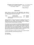
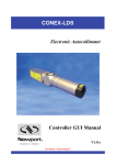
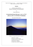
1
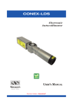
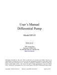
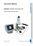
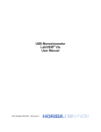
Specification of the varied-line-spacing plane grating
monochromator for the TPS port-24 beamline at NSRRC
July, 2014
Copyright © 2014 National Synchrotron Radiation Research Center (NSRRC) . This
document is the property of National Synchrotron Radiation Research Center (NSRRC) . No
exploitation or transfer of any information contained herein is permitted in the absence of an agreement with
NSRRC, and neither the document nor any such information may be released without the written consent of
NSRRC.
National Synchrotron Radiation Research Center (NSRRC)
101 Hsin-Ann Road, Hsinchu Science Park,
Hsinchu 30076, Taiwan
Table of Contents
I. INTRODUCTION......................................................................................................................................... 1
1. Purpose...........................................................................................................................................................1
2. Scope of specification ...................................................................................................................................1
II. SPECIFICATION AND REQUIREMENTS…….........................................................................................2
1. Introduction....................................................................................................................................................2
2. Axis rotation mechanism................................................................................................................................3
3. Plane mirror and grating holders....................................................................................................................4
4. Protection plates.............................................................................................................................................4
5. Cooling system...............................................................................................................................................4
6. Specifications of the pitch axis of plane mirror and gratings ........................................................................5
7. Specifications of switch of the plane mirror and gratings..............................................................................5
8. Adjustments plane mirror and gratings..........................................................................................................5
9. Chamber.........................................................................................................................................................6
10. Monochromator installation and alignment.................................................................................................7
11. Vibrations of the monochromator.................................................................................................................7
12. Vibrations of the plane mirror and gratings…………………......................................................................8
13. Bake-up system……………........................................................................................................................8
14. Bakeout stability………………………………………………………………….......................................8
15. Vacuum…………….....................................................................................................................................8
16. Electrical system, motors and controls…………….....................................................................................9
III. FACTORY ACCEPTANCE TEST (FAT)...............................................................................................10
IV. WATER AND ELECTRICITY……………...............................................................................................12
V. DAMAGEABLE PARTS…………….........................................................................................................12
VI. DRAWINGS……………..........................................................................................................................12
VII. USER MANUAL…………….................................................................................................................13
VIII. QUALITY AND ASSURANCE……………………………………………………….........................13
IX. PREPARATION FOR DELIVERY…………….......................................................................................13
Appendix: Drawings……………....................................................................................................................15
I. INTRODUCTION
1. Purpose
This document contains the specifications for a variable-line-spacing (VLS) plane grating
monochromator (PGM) (SX-700 type) for the TPS port-24 beamline (Fig. 3) at the National
Synchrotron Radiation Research Center (NSRRC).
2. Scope of specification
1.1
1.2
1.3
1.4
1.5
1.6
The monochromator fabrication, including
(1) The monochromator chamber
(2) One plane mirror holder
(3) Three Grating holders
(4) Plane mirror scan mechanism
(5) Gratings scan mechanism
(6) P1ane mirror switching mechanism
(7) Gratings switching mechanism
(8) Position and orientation adjustment mechanism of the chamber
(9) Vacuum system (including 400 l/s Ti sublimation ion pump, turbomolecular pump (8
inch flange), manual valve (8 inches CF) with metric threads, two pneumatic valves (4.5
inches CF) with metric threads, gauges with the controller and so on)
(10) Bake-up system
(11) Contro1 system (including two water coolers, the water flow rate is 2 L/min; reservoir
capacity 13 liters)
(12) Water cooling system for plane mirror and gratings
(13) Mirror and grating installation tools
(14) A granite base shall be used to decrease the vibrations of the monochromator.
Factory acceptance test
Packing and transportation
Installation at NSRRC
Final acceptance test at NSRRC
Providing once free service on NSRRC’s Jobsite in the first year
1
II. SPECIFICATION AND REQUIREMENTS
1. Introduction
Fig. 1 The optical layout of the VLS plane grating monochromator
Energy range
200eV~2600eV
Work mode
Fixing incoming and outgoing beams
Number of plane mirror
1 (side water cooled)
Number of grating
3 (side water cooled)
Dispersion plane
vertical
Rotation range
Plane
mirror
Accuracy
Repeatability
θ = -0.5∘~ 12∘
VLS
grating
90 - α = -0.5∘~ 16∘
Plane
mirror
≤ ±0.5 arcsec in the full range
VLS
grating
≤ ±0.5 arcsec in the full range
Plane
mirror
≤ ±0.05 arcsec in the full range
VLS
grating
≤ ±0.05 arcsec in the full range
2
Rotation resolution
Optical size
(Fig. 5 and Fig. 6)
Plane
mirror
≤ ±0.05 arcsec in the full range
VLS
grating
≤ ±0.05 arcsec in the full range
Plane
mirror
70 mm × 400 mm × 60 mm
VLS
grating
30 mm × 220 mm × 30 mm
(three gratings have the same size)
Distance between incoming
and outgoing beam (h)
20 mm
Entrance and exit flange size
63 mm (inner diameter)
Incoming beam angle
2.4∘
Outgoing beam angle
2.4∘
The
maximum
distance
between the outside edge of
the entrance flange and the
center of the grating.
600 mm
The
maximum
distance
between the outside edge of
the exit flange and the center
of the grating.
250 mm
≤ 2 × 10⁻¹⁰ torr
Vacuum
Table 1 Main specifications of the VLS plane grating monochromator
The optical layout of the VLS plane grating monochromator is shown in Fig. 1. There are one
plane mirror and three VLS gratings in the monochromator chamber. Each grating can be moved
into the beam along the x axis. The plane mirror contains two coating areas. Each coating area of
the plane mirror can also be switched into and out of the beam along x axis. The main
specifications of the VLS plane grating monochromator are shown in table 1.
2. Axis rotation mechanism
The axis rotation mechanism of the plane mirror and the VLS grating is shown in figure 2. The
grating rotation axis is GRC (0 mm, 0 mm). The plane mirror rotation axis is MCR (0 mm, 10 mm).
Distance between the plane mirror axis and its surface is D = 20mm. Distance between the right
3
edge of the mirror and the perpendicular foot of the axis is d = 45 mm. The tolerances are all ±5μm
in vertical and horizon directions.
Fig.2 Axis rotation mechanism of the plane mirror and the grating
The synchronous rotation of both the plane mirror and grating shall be mechanically independent,
i.e., each mechanism has its own drive system with motors, encoders, and associated electronics.
Synchronization is achieved via the computer control system. Sine bar structure shall be used in
the rotation mechanism of the plane mirror and gratings. The contractor shall provide the FEA
analysis of the stress of the sine bar. Two UHV compatible angle encoders, the Renishaw RESR
series, are recommended to be provided to directly measure the rotation angles of the grating and
the plane mirror. Other equivalent device can also be accepted but shall be approved by NSRRC.
3. Plane mirror and grating holders
The plane mirror and gratings shal1 be adiabatic with the holders. UHV compatible wires shall be
connected to the edge of the surface of the plane mirror and gratings to measure the photon
current from the surface of each optical element. The wires shall not damage the optical area on
the surfaces of the plane mirror and the gratings. The wires shall be connected outside the
chamber through flange.
4. Protection plates
Protection plates shall be installed at the upstream side surface of each optical element to prevent
the side surface being illuminated by the SR beam. The protection plates shall be electronically
insulated from other parts. The protection plates shall be gold coated and connected outside the
chamber by UHV compatible wires to monitor the photocurrent on the protection plates. The
protection plates of all the gratings can be connected together. The protection plate of the plane
mirror shall be connected separately. The protection plates shall be water cooled.
5. Cooling system
The plane mirror and all gratings will be side-water-cooled. The surface of the cooling plate
contacted to the grating shall have the flatness less than 25 μm. The tubes for water cooling
systems have to be low-vibration flexible hoses. All cooling water tube of the plane mirrors and
gratings shall be surrounded by low vacuum guard tubes with the pressure of ~mTorr. The water
flow rate, the pressure at the outlet and the water temperature shall be measured. The values shall
be sent to NSRRC monitor system. The cooling circuit of each grating and the protection plates
shall be in series, which shall be isolated with that of the plane mirror. The water flow rate is 2
4
L/min and reservoir capacity is 13 liters.
6. Specifications of the pitch axis of plane mirror and gratings
The angle between the pitch axis of plane mirror and gratings shall be less than 4 arcsec in roll and yaw.
The radial vibration of the pitch axis of both the plane mirror and the gratings shall be less than 0.5μm
during the full rotation range.
7. Specifications of switch of the plane mirror and gratings
During the switch, the plane mirror and the gratings will move along their respective switch axis.
7.1 Switch range
Plane mirror: Each center of the two coating areas can be moved into the beam position.
Gratings: The switch range of the gratings shall be determined according to the distance between
each neighbor grating. Each grating center can be moved into the beam position. More 10mm
shall be provided on each side in the switch range for both the plane mirror and gratings.
7.2 Parallelism between switch direction and pitch axis
The angle between switch direction and pitch axis of plane mirror shall be less than 30 arcsec.
The angle between switch direction and pitch axis of gratings shall be less than 3 arcsec.
7.3 Repeatability of the optics at every switch position
Plane mirror: Height: < ±3 μm; Rol1: < ±0.24 arcsec; Yaw: < ±10 arcsec; Pitch: ≤ 0.1 arcsec
Gratings: Height: < ±1 μm; Rol1: < ±0.24 arcsec; Yaw: < ±10 arcsec; Pitch: ≤ 0.1 arcsec
8. Adjustments plane mirror and gratings
In atmospheric pressure (Coarse adjustment)
Range
Plane mirror
Grating
Height (z)
±3 mm
Pitch
±2∘
Roll
±3∘
Height (z)
±3 mm
Pitch
±2∘
Roll
±3∘
Yaw
±2∘
In vacuum (fine adjustment of the grating in the operation position actuated from outside the
5
chamber when the chamber is under the vacuum)
The plane mirror and each grating shall be able to be aligned manually in vacuum. The
specifications of the alignments are listed below.
Plane mirror
Grating
Range
Resolution
Height (z)
±0.1 mm
< 1μm
Pitch
±0.05∘
0.5 arcsec
Roll
±0.05∘
0.5 arcsec
Height (z)
±0.1 mm
< 1μm
Pitch
±0.05∘
0.5 arcsec
Roll
±0.05∘
0.5 arcsec
Yaw
±0.05∘
0.5 arcsec
9. Chamber
This ultra-high vacuum chamber must be fitted with ports appropriate for incoming and outgoing
beams, pumping, pressure gauges, turbomolecular pump, Ti sublimation pumping (This port
needs a mask to avoid Ti coating on the surface of the optical components), discharge cleaning
etc. and the following specific features:
9.1 A grating observation viewport which allows viewing of the entire ruled surface of the grating
in the operation position.
9.2 A grating adjustment 8 inch viewport which allows viewing of the yaw, roll, or pitch
adjustment of the grating in the operation position. A removable port should be large enough
(i.e. 14 inch) for grating holder installation.
9.3 A grating carriage observation viewport which allows viewing of the selection grating motion.
9.4 An arrangement of viewport (either the one large grating viewport described in item 9.2 or a set
of other viewports) for He-Ne laser alignment using the ports from the grating at large grazing
angles of incidence.
9.5 Ion gauge and two spare 2.75 inch ports.
9.6 The chamber shall be made of Stainless Steel AISI 316L and the standard flange material shall
be Stainless Steel AISI 304L. Inside the chamber, stainless steel should be type 304L,
aluminum should be type 6061-T6, all ceramics must be vacuum fired to minimize water
content, all fastening screws must be silver plate. To absorb the bremsstrahlung radiation, the
chamber wall thickness shall be no less than 3mm. The observing window shal1 be made of
lead (Pb) glass (7056 glass steel viewport). The thickness of the observing window shall be no
less than 6mm and its density shall be no less than 4.5 g/cm3. The use of the types of materials
6
(including any ultra-high vacuum lubricants) is subject to NSRRC approval.
9.7 The monochromator chamber shall have the ability of manual adjustment in XYZ directions
and roll, yaw and pitch rotations. The specifications of other adjustment are listed below.
Range
Resolution
X
±15 mm
0.01 mm
Y
±15 mm
0.01 mm
Z
±25 mm
0.01 mm
Pitch
±1.5∘
5 arcsec
Roll
±1.5∘
5 arcsec
Yaw
±1.5∘
5 arcsec
10. Monochromator installation and alignment
The contractor shall be responsible for installation and alignment of the monochromator after
delivery to NSRRC with the assistance of NSRRC, including:
1. The installation and alignment method, which shall be approved by NSRRC.
2. Install the monochromators to the beamline.
3. Align the pitch axis of gratings to make the angle between it and x axis less than 4 arcsec. x
axis shall be defined and supplied by the NSRRC coordination system.
4. Install the plane mirror and gratings to the chamber. The plane and two gratings shall be
installed into the chamber after the monochromator shipment to NSRRC.
5. Align the roll of plane mirror with the error less than 0.1 arcsec.
6. Align the roll of gratings to make the error less than 0.1 arcsec.
7. Align the yaw of gratings to make the error less than 30 arcsec.
8. Align the distance between the surface of plane mirror and its pitch axis to make the error less
than 5μm.
9. Align the distance between the surface of each grating and its pitch axis to make the error less
than 5μm.
10. Align the chamber to make that the surface center of the grating is 1705 mm.
11. Vibrations of the monochromator
7
A granite base shall be used to decrease the vibrations of the monochromator. NSRRC will supply
the vibration frequency spectrum of the ground. The contractor shall measure the vibration
frequency spectrum of the monochromator. The frequency of the vibration spectrum of the
monochromator system shall be greater than 20Hz.
12. Vibrations of the plane mirror and gratings
The RMS vibrations of the plane mirror and gratings should be less than 0.01 arcsec (measured by
the rotary encoders) at the manufacture’s factory.
13. Bake-up system
The power supply is 220V (60Hz). Heating wires shall be installed surrounding the chamber for
baking-up. Automatic temperature controller shall be supplied to control the baking temperature.
The baking-up temperature increasing/decreasing speed shall not exceed l5 ℃/hr with optics.
The final baking process with optics at NSRRC shall be monitored by NSRRC.
14. Bakeout stability
The baking-up temperature increasing/decreasing speed shall not exceed l5 ℃/hr with optics.
After a standard 120 ℃ bakeout of this grating chamber (the chamber has already met the
vacuum requirement of 15), the z-position of all gratings must be maintained within 2 μm of their
positions before baking and the yaw, roll, and pitch angles must be maintained within 0.5 arcsec.
15. Vacuum
The product must meet the following vacuum requirements
15.1 No organic or high vapor pressure inorganic materials may be on any of the internal parts or
on the vacuum side of the chamber wall after final clean.
15.2 The chamber without encoders and optics shall be baked at 150℃ for 7 days.
15.3 Prior to shipping, the contractor shal1 assemble, pump down, bake, and vacuum test the entire
UHV assembly. This bake will be done without optics. A high sensitivity quadrupole type
residual gas analyzer (RGA) shall be used to test for unacceptable mass peaks from 1 amu to
at least 80 amu. The test results shall satisfy the fol1owing table. The residual gas analysis,
bakeout, and vacuum data shall then be provided to NSRRC for approval prior to shipment.
Suitable well baked
AMU 2 > 5× AMU 18
Leak tight
AMU 28 > 4× AMU 32
AMU 14 < AMU 16
General Contaminants
< 0.1 % of total pressure
Chlorine Residue
< 0.1% of total pressure
(sum of AMUs 35 and 37)
Hydrocarbon
< 0.1% of total pressure
Residue
(sum of AMUs 69 and 77)
15.4 The grating chamber and all of its internal parts must not produce carbon-containing vacuum
contaminants at partial pressures above 1×10-12 Torr after normal bakeout procedures in
ultra-high vacuum, i.e. pressures less than 1×10⁻¹⁰ Torr with 400 liters/sec pumping speed
through the pumping port. The total leak rate as measured by stand He leak detection
8
techniques must be less than 2×10⁻¹⁰ atm cc/sec He.
15.5 All flanges shall be of the conflat type unless approved by NSRRC. All vacuum gauge heads
shall be out of line of sight of any optical surfaces. Al1 vacuum gauges shall be supplied by
NSRRC. A suitable port with a metal sealed roughing valve shall be available for initial
evacuation with a turbo pump. The turbo pump wil1 be supplied by NSRRC. The contractor
shall supply the turbo pump in factory test. The UHV assembly shall be sealed and pumped to
low vacuum prior to shipment. No water to vacuum joints, welds, or brazed joints are
permitted.
16. Electrical system, motors and controls
The power supply is 110V (60Hz). 5-phase stepping motors shall be used to drive the rotation and
switch of the plane mirror and gratings. The contractor shall choose the motors and drivers which
will be approved by NSRRC. The contractor shall provide the control system outside the chamber.
The control system of the plane mirror and gratings shall have the software interface for Labview
programming and EPICS control. To compensate the energy drift, the control system shall move
the energy to the set value according to the readback from the encoder every 10 seconds when the
monochromator is not in moving or scanning operation. This function can be turned on and off in
the software interface. The contractor shall provide both software and hardware protection to
prevent collision between the gratings and the plane mirror. The coordinated scan of the plane
mirror and grating over their full scanning range shall be done in less than 10 minutes. Type K
thermocouples shall be installed on the side surface of each grating and plane mirror for
monitoring the bulk temperature on the optics. The signals of the thermocouples shall be
connected outside the chamber. The temperature of the holders of plane mirror and gratings shall
be monitored by type K thermocouples. The temperature of the encoders shall be monitored by
type K thermocouples. All motor drivers、cables and motion controllers required to operate the
monochromator should be supplied by the manufacturer. Generally the cable between the driver
and motor shall be 20 m in length. Proposals for full control system including software should be
included in the tender. The supplier are strongly encouraged to make recommendations on control
system that may lead to an improvement in performance, efficiency, reliability, safety, or a
reduction in cost.
16.1 Monochromator control system
NSRRC has applied the EPICS control system tool kit for the NSRRC accelerators, beamlines
and conventional facilities. The monochromator control system shall be based on this standard
to enable cost effective and seamless integration with the rest of the facilities on NSRRC.
NSRRC beamline control system is based on Galil 4080 motion controller and EPICS. The
contractor is required to supply the control system in EPICS. All the motors should be driven
by the EPICS Motor Record. We recommend the supplier to use the same controller. Other
motion controller shal1 be approved by NSRRC. The supplier must take responsibility for
ensuring the motion controller chosen can realize the performance required. The supplier shall
present the outline design for the control system at tender return. Detail design, including
choice of hardware the specifications of the hardware the control functionality description, the
software and hardware requirements to control the motors list of control parameters and
description of the operator interfaces must be presented at the design review to be approved
by NSRRC.
16.2 Limit switches
9
Each actuated drive shall include two limit switches to define the two extreme positions of
each motion and one limit switch to define the home position. The limit switches should be
the mechanical switches. Wherever possible the limit switches shall be externally mounted
and manually adjustable, and shall have NC (normally closed) contacts. Information regarding
the proposed switches shall be submitted to NSRRC for approval. Limit switch connector
brackets are to be provided by the contractor.
16.3 Cabling
All cable and wiring must be LSOHFR (Low Smoke, Zero Halogen, Fire Retardant) unless
specifically agreed otherwise complying with IEC 60754-1 and IEC 60332. The oxygen index
must be higher than 28 and acid gas emission less than 4% for the outer sheath. PVC
compound must not be used. Where movement is required, cable must be highly f1exible
having minimal effect on mechanical performance, but offering suitable mechanical
protection. The equipment is to be suitably earthed with all sub-assemblies and components
bonded to a main earth terminal. All cables are to be identified at both ends using cable
markers applied to the cable by using a carrier strip and cable ties. Al1 visible cores of the
cable are to be identified such that they can be related to their associated multi-pair cable. The
supplier shall install one control rack/box to route and connect the electrical cables from the
f1anges. The motor and limit switches cables should be connected from the control box to the
drivers. We recommend the control box is also used for other signals except the encoder
signals. The cables and connectors between the f1anges and the control box should be tight
and reliable. It is the responsibility of the contractor to use some protected methods from
easily loosing while being touched. The connectors of the motors and limit switches in the
control box should use Souriau connectors and its pins to ensure the electrical wiring reliable.
16.4 Electrical standards
The equipment purchased, or constructed for NSRRC are required to comply with the
standard of safety and general product safety applied in Taiwan.
III. FACTORY ACCEPTANCE TEST (FAT)
The contractor shall provide a test plan for the factory acceptance test including the test methods
and tools, which shall be approved by NSRRC. The following tests and corresponding testing
procedures shall be provided by the contractor before the delivery.
1. Test showing compliance with vacuum requirements described above. The leak rate and
maximum vacuum without optics shall be provided.
2. Residual gas analyzer test showing compliance with the requirements described above.
3. The parallel integrity of the rotation axes and synchronization of the scan angles for both the
plane mirror and grating optical surfaces shall be demonstrated to be better than 0.1 arcsec in
both pitch and roll using autocollimation over the zero order scan range.
4. Autocollimator results (turning on water coolers) showing the resolution and repeatability of
the plane mirror and grating rotations. The accuracy of the autocollimator shall be 0.05 arcsec.
The short term RMS vibrations measured with autocollimator shall be less than 0.1 arcsec.
5. Autocollimator results (turning on water coolers) showing the long term (more than 24 hours)
stability of the plane mirror and grating position. The vibration in any short period (~ ten
10
seconds) during the long period shall be no more than 0.1 arcsec (RMS).
6. Long term stability test of the plane mirror and grating position (read from encoders), which
shall be no more than 0.01 arcsec (RMS).
7. Autocollimator results showing the repeatability of the switch mechanism of the plane mirror
and gratings which shall be satisfy the requirements described above.
8. Figure 3 describes the relation between the position of optical components and time, which ∆θ
shall be no more than 0.1 arcsec (RMS) and ∆t shall be no more than 1 sec.
Fig.3 The relation between the position of optical components and time
9. Test data of the surface flatness of the cooling plates for the gratings.
10. Test data of the insulation between the mirror/gratings and their holders, which shall show a
current less than 2E-14 A measured with a picoammeter.
11. Test data of the insulation between the protection plates and other parts, which shall show a
current less than 2E-14 A measured with a picoammeter.
12. Vibration frequency spectrum test of the monochromator. The frequency of the vibration
spectrum of the monochromator system shall be greater than 20Hz.
13. Collision protection test (both software and hardware) between the gratings and the plane
mirror.
14. Mechanical test. Including:
(1) Range and limit switches of the mirror and grating rotation drive.
(2) Range and limit switches of the mirror and grating translation drive.
(3) Repeatability tests of the mirror and grating translation drive.
(4) Range and resolution tests of the in-vacuum-adjustments mechanism of plane mirror and
gratings.
(5) Range and resolution tests of the chamber adjustment mechanism.
15. Control test. The tests include control and operation for monochromator, including: any or all
of the controls and safety interlock specified in the technical specification.
16. Test of the sine bar length.
17. Test of the cooling circuit. The cooling circuit should be filled under 0.3MPa pressure for at
least 1 hour without optics.
11
After de1ivery to NSRRC, all the tests listed above shall be performed again.
The acceptance shall be done when all the tests results satisfy the requirements and all the
installation and alignments are finished according to the requirements.
IV. WATER AND ELECTRICITY
1. The contractor shall provide the request on water and electricity of the monochromator.
2. The power supply in NSRRC is 220V (60Hz), 110V (60Hz) and Taiwanese style sockets.
The electrical systems use 110V (60Hz) and the bake-up system uses 220V (60Hz).
3. Two water coolers shall be used to supply cooling water for the plane mirror and gratings,
respectively. The temperature of the cooling water shall be from 1℃ to 40℃ and 0.01℃
temperature stability. The pressure flow rate of the cooling water is 12 to 25 L/min (5-speed).
V. DAMAGEABLE PARTS
The contractor shall supply the list of the damageable parts and some spare parts, which shall be
approved by NSRRC.
VI. DRAWINGS
The drawings of the monochromator including the granite base shall be approved by NSRRC
before the manufacture. The contractor shall supply the drawings of the following parts of the
monochromator to NSRRC.
1. The cooling circuit connector with the plane mirror and the gratings
2. The assembly drawing of the parts inside the chamber
3. The mirror and gratings holders
4. The grating chamber
5. The grating scanning system
6. 3D assemble drawing including all parts
7. Drawings of the damageable parts
8. Electrical drawings
Electrical drawings must be provided in AutoCAD 2D format or PDF format to the requirements of
NSRRC. Full maintenance information must be provided, sufficient to locate faults down to
individual electronic component level, including but not limited to:
(1) System blocks diagram and general assembly drawings.
(2) Sub-assembly drawings including component layout and electrical schematics.
(3) Setting up calibration or configuration instructions user manual if required.
(4) The detail lists for al1 electronic components (motors, encoders, limit switches, connectors, pins
12
and thermal sensors) include the types, series manufactures and its contact information.
(5) The detail lists for all spare components.
VII. USER MANUAL
The contractor shall supply the detailed user’s manual of the monochromator to NSRRC.
VIII. QUALITY AND ASSURANCE
1. Responsibility for inspection
Unless otherwise specified in the contract or order, the supplier is responsible for the performance
of all inspection requirements as specified herein. Except as otherwise specified, the vendor may
utilize his own facilities or any commercial laboratory acceptable to NSRRC. NSRRC reserves
the right to perform any of the inspections and set forth in the specification where such
inspections are deemed necessary to assure supplies and services conform to prescribed
requirements.
2. Inspection of final design
In order to meet these specifications, NSRRC reverses the right to inspect and require alterations
of the completed designs of the grating chamber and its internal mechanisms. Agreement between
NSRRC and the vendor on the entire design drawings must be occurred before any actual
fabrication process begins.
3. Precision and stability
The vendor will install the ruled grating into the grating chamber and provide evidence (must be
in conjunction with a NSRRC representative) that the specifications stated herein with respect to
precision and stability of the various motions have been satisfied. This will generally include
various laser alignment and laser interferometer tests.
4. Alignment aids
For alignment and testing of the grating chamber on the NSRRC floor, the vendor will provide a
means of generating a reference line parallel to the line which passes through the pole of each
grating (e.g. drill < 2mm holes through the center of the grating carriage pivots), or provide a
space at the center of the grating carriage pivots for an alignment target.
5. Vacuum requirements compliance
The vendor shall supply NSRRC with evidence that the completed grating chamber meets the
vacuum compatibility requirements in paragraph 15. Vacuum in II. SPECIFICATION AND
REQUIREMENTS. The nature of the test used to ensure compliance shall be a residual gas
analysis at ultra-high vacuum (UHV) pressures (≤ 1 × 10⁻¹⁰ Torr). NSRRC must approve the
details of the test method proposed by the vendor and will offer guidance as to how the test shall
be performed if so requested. Use of the services of an independent testing laboratory is subject to
the approval of NSRRC.
IX. PREPARATION FOR DELIVERY
13
1. The finished pieces must be thoroughly clean and free from any organic low-vapor pressure material
or cutting fluid. The pieces must meet UHV requirements outlined in paragraph 15. Vacuum in II.
SPECIFICATION AND REQUIREMENTS.
2. Packaging
The grating chamber must be packaged in such a way that foreign materials (gases, particulates, etc.)
can not enter the UHV portions of the chamber. The suggested method of accomplishing this
requirement is to ship the chamber in a sealed state filled with slight larger than 1 atm dry nitrogen.
The packaging method is subject to NSRRC approval.
3. Packing
Packing for shipment must insure that the grating chamber is insulated from severe shock and rough
handling. Package markings shall indicate the fragile nature of the contents.
4. Before the delivery the vendor shall supply the factory acceptance test (FAT) and the FAT shall be
approved by NSRRC.
14
Appendix: Drawings
TOP VIEW
177.6
Sin
VFM
1
HFM
1.35
VFM
7
2
26
Sin
0.02
177.6
28
0.98
VLSG VRFM
PM
177.6°
34.994 35.992 36.971
Fig.4 The layout of the TPS port-24 beamline
Fig.5 The drawing of the plane mirror (PM)
15
5.02
Sout
1.746
SIDE VIEW (UNITS: m)
0
Sout
VRFM
PM
HFM
S
VLSG
1.705
S
41.991
Fig.6 The drawing of the grating
16