1
MAPLOGIC CORPORATION
GIS Software Solutions
MapLogic Layout Manager
User’s Manual
MapLogic Layout Manager User’s Manual
2015 MapLogic Corporation
All Rights Reserved
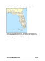
330 West Canton Ave., Winter Park, Florida 32789
Phone (407) 657-1250 • Fax (407) 657-7008
MapLogic Layout Manager is a trademark of MapLogic Corporation.
ArcGIS, ArcMap and ArcView are registered trademarks of ESRI.
Table of Contents
Introduction _____________________________________________________________________ 1
What Is MapLogic Layout Manager? ____________________________________________ 1
MapLogic Layout Manager User Interface ____________________________________________ 2
The MapLogic Layout Manager Toolbar _________________________________________ 2
The Layouts Dockable Window ________________________________________________ 4
Element Properties __________________________________________________________ 4
Before You Get Started ____________________________________________________________ 6
How MapLogic Layout Manager Changes The ArcMap Document ____________________ 6
Different Licenses For The MapLogic Layout Manager _____________________________ 6
Basic Concepts ___________________________________________________________________ 9
Multiple Layouts Within The ArcMap Document __________________________________ 9
The Map Series Layout _______________________________________________________ 9
The Map Book Layout ______________________________________________________ 10
New Elements You Can Add To Map Series And Book Layouts _____________________ 11
Two-Sided Map Book Setup And Printing _______________________________________ 18
Where To Go From Here?____________________________________________________ 18
Working With Expressions ________________________________________________________ 19
The MapLogic Expression Builder Dialog _______________________________________ 19
Reserved Words ___________________________________________________________ 20
Database Fields ____________________________________________________________ 22
Text Formatting Tags _______________________________________________________ 25
The Label Expression _______________________________________________________ 25
Verifying That An Expression Is Correct ________________________________________ 25
Quickly Generating A Map Series Or Map Book _______________________________________ 26
The Book Wizard __________________________________________________________ 26
MapLogic Layout Manager User’s Manual
Page i
Creating Map Series Index Layers __________________________________________________ 34
The Grid Wizard ___________________________________________________________ 34
Grid An Area______________________________________________________________ 35
Follow A Line _____________________________________________________________ 38
Layer To Grid _____________________________________________________________ 41
Single Grid _______________________________________________________________ 42
Editing Grids ______________________________________________________________ 42
Generating The Index Layer __________________________________________________ 44
Managing Page, Map Series And Book Layouts _______________________________________ 45
Displaying Popup Menus In The Layouts Dockable Window ________________________ 45
Creating A New Layout _____________________________________________________ 46
Copying An Existing Layout__________________________________________________ 46
Moving Back And Forth Between Layouts_______________________________________ 47
Renaming Layouts _________________________________________________________ 47
Removing (Deleting) Layouts_________________________________________________ 47
Rearranging Layouts ________________________________________________________ 48
Managing Page and Map Series Layout Properties_________________________________ 48
Managing Map Book Properties _______________________________________________ 48
Managing Section Properties _________________________________________________ 49
Page Numbering ___________________________________________________________ 50
Master And Alternate Templates ______________________________________________ 51
Where To Go From Here?____________________________________________________ 54
The Map Series Frame ___________________________________________________________ 55
What Is A Map Series Frame? ________________________________________________ 55
Adding A Map Series Frame To A Layout _______________________________________ 55
Converting An Existing Data Frame To A Map Series Frame ________________________ 56
Modifying The Properties Of A Map Series Frame ________________________________ 57
Modifying The Series Properties Of A Map Series Frame ___________________________ 57
Modifying The Scale Properties Of A Map Series Frame ___________________________ 59
Modifying The Adjacent Page Listing Properties Of A Map Series Frame ______________ 61
Modifying The Coordinate System Of A Map Series Frame _________________________ 64
Modifying The Definition Queries Of Layers In A Map Series Frame _________________ 65
Modifying The Options Of A Map Series Frame __________________________________ 69
Modifying The Custom Code Of A Map Series Frame _____________________________ 72
MapLogic Layout Manager User’s Manual
Page ii
The Thematic Series Frame _______________________________________________________ 76
What Is A Thematic Series Frame?_____________________________________________ 76
Adding A Thematic Series Frame To A Layout ___________________________________ 76
Converting An Existing Data Frame To A Thematic Series Frame ____________________ 77
Modifying The Properties Of A Thematic Series Frame ____________________________ 78
Adding, Removing, Rearranging And Activating Themes ___________________________ 78
Modifying The Custom Code Of A Thematic Series Frame__________________________ 80
Editing The Properties Of A Theme ____________________________________________ 82
Modifying The Layer Visibility Properties Of A Theme ____________________________ 83
Modifying The Layer Order Properties Of A Theme _______________________________ 83
Modifying Map Extent Of A Theme____________________________________________ 84
Modifying Custom Text Of A Theme___________________________________________ 86
Modifying The Options A Theme______________________________________________ 87
The Series Locator Frame _________________________________________________________ 88
What Is A Series Locator Frame? ______________________________________________ 88
Adding A Series Locator Frame To A Layout ____________________________________ 88
Converting An Existing Data Frame To A Series Locator Frame _____________________ 88
Modifying The Properties Of A Series Locator Frame ______________________________ 89
Modifying The Locator Properties Of A Series Locator Frame _______________________ 90
Modifying The Current Page Symbol Properties Of A Series Locator Frame ____________ 92
Modifying The Options Of A Series Locator Frame _______________________________ 93
The Series Key Frame ____________________________________________________________ 95
What Is A Series Key Frame? _________________________________________________ 95
Adding A Series Key Frame To A Layout _______________________________________ 95
Converting An Existing Data Frame To A Series Key Frame ________________________ 96
Modifying The Properties Of A Series Key Frame_________________________________ 97
Modifying The Key Properties Of A Series Key Frame _____________________________ 97
Modifying The Key Labels Properties Of A Series Key Frame _______________________ 98
Modifying The Options Of A Series Key Frame _________________________________ 100
The Dynamic Legend Element ____________________________________________________ 102
What Is A Dynamic Legend Element? _________________________________________ 102
Adding A Dynamic Legend Element To A Layout _______________________________ 103
Modifying The Properties Of A Dynamic Legend Element _________________________ 103
Modifying Legend Source Properties Of A Dynamic Legend Element ________________ 105
MapLogic Layout Manager User’s Manual
Page iii
Modifying Dynamic Layers Properties Of A Dynamic Legend Element _______________ 107
Modifying Options Of A Dynamic Legend Element ______________________________ 109
The Detail Frame _______________________________________________________________ 111
What Is A Detail Frame?____________________________________________________ 111
Adding A Detail Frame To A Layout __________________________________________ 111
Modifying The Properties Of A Detail Frame ___________________________________ 112
Modifying The Source Of A Detail Frame ______________________________________ 114
Modifying Detail Map Size/Scale Of A Detail Frame _____________________________ 116
Modifying The Layers Of A Detail Frame ______________________________________ 118
Modifying The Title Of A Detail Frame ________________________________________ 119
Modifying Detail Frame Options _____________________________________________ 121
The Series Text Element _________________________________________________________ 122
What Is A Series Text Element? ______________________________________________ 122
Adding A Series Text Element To A Layout ____________________________________ 122
Converting An Existing Text Label To A Series Text Element ______________________ 122
Modifying The Properties Of A Series Text Element ______________________________ 123
Modifying The Series Text Properties Of A Series Text Element ____________________ 125
The Geo-Text Element ___________________________________________________________ 127
What Is A Geo-Text Element? _______________________________________________ 127
Adding A Geo-Text Element To A Layout______________________________________ 127
Converting An Existing Text Label To A Geo-Text Element _______________________ 128
Modifying The Properties Of A Geo-Text Element _______________________________ 129
Modifying The Text Source Properties Of A Geo-Text Element _____________________ 130
Modifying The Query Point Properties Of A Geo-Text Element _____________________ 132
Modifying Options Of A Geo-Text Element ____________________________________ 134
The Page Index Element _________________________________________________________ 136
What Is A Page Index Element _______________________________________________ 136
Adding A Page Index Element To A Layout ____________________________________ 137
Modifying The Properties Of A Page Index Element ______________________________ 137
Modifying The Index Source Properties Of A Series Index Element __________________ 138
Modifying The Index Layout Properties Of A Page Index Element___________________ 141
Modifying The Display And Sort Order Properties Of A Page Index Element __________ 145
Modifying The Options Of A Page Index Element________________________________ 146
The Series Index Element ________________________________________________________ 150
MapLogic Layout Manager User’s Manual
Page iv
What Is A Series Index Element ______________________________________________ 150
Adding A Series Index Element To A Layout ___________________________________ 151
Modifying The Properties Of A Series Index Element _____________________________ 151
Modifying The Index Source Properties Of A Series Index Element __________________ 152
Modifying The Index Layout Properties Of A Series Index Element__________________ 155
Modifying The Display And Sort Order Properties Of A Series Index Element _________ 160
Modifying The Options Of A Series Index Element_______________________________ 161
Creating Index Databases ________________________________________________________ 165
What Is An Index _________________________________________________________ 165
The Indexing Wizard_______________________________________________________ 165
Indexing Maps____________________________________________________________ 167
Indexing Layers___________________________________________________________ 168
Indexing Boundaries _______________________________________________________ 170
Output Columns __________________________________________________________ 172
Sort Order _______________________________________________________________ 174
Output __________________________________________________________________ 175
The Legend Symbol Labeler ______________________________________________________ 178
What Is The Legend Symbol Labeler? _________________________________________ 178
Displaying the Legend Symbol Labeler Dialog __________________________________ 178
The Expression Tab________________________________________________________ 180
Database Fields ___________________________________________________________ 181
Formatting Statements _____________________________________________________ 182
The Label Expression ______________________________________________________ 183
The Options Tab __________________________________________________________ 184
Options _________________________________________________________________ 185
Tool Options _____________________________________________________________ 186
Applying The Expression to the Legend’s Symbol Labels __________________________ 187
Creating Legend Symbol Expressions _________________________________________ 187
The Different Parts Of An Expression _________________________________________ 188
Database Fields ___________________________________________________________ 188
Database Field Summary Methods ____________________________________________ 188
Formatting Statements _____________________________________________________ 189
Legend Label and Value ($$Label and $$Value) _________________________________ 191
Plain Text _______________________________________________________________ 191
MapLogic Layout Manager User’s Manual
Page v
Modifying The Anchor Properties Of An Element ________________________________ 193
Modifying The Primary Anchor Properties Of An Element _________________________ 194
Anchoring Elements ____________________________________________________________ 196
What Is Anchoring An Element? _____________________________________________ 196
Adding Anchor Properties To An Existing Element_______________________________ 196
Accessing The Anchor Properties Of An Element ________________________________ 197
Modifying The Anchor Properties Of An Element ________________________________ 198
Modifying The Primary Anchor Properties Of An Element _________________________ 199
Modifying The Alternate Anchor Properties Of An Element ________________________ 201
Modifying The Anchor Options Of An Element__________________________________ 203
Previewing, Printing And Exporting Map Series And Map Books ________________________ 205
Previewing Map Series Or Map Book Pages ____________________________________ 205
Printing A Map Book ______________________________________________________ 207
Exporting A Map Book _____________________________________________________ 208
Selecting Print And Export Page Ranges Using List, Map or Query __________________ 210
Miscellaneous Tools_____________________________________________________________ 214
Search And Replace Text In Layouts __________________________________________ 214
Copy Layers To Multiple Layouts ____________________________________________ 217
Merge PDFs _____________________________________________________________ 221
Remove All MapLogic Multi-Page Objects From MXD ___________________________ 221
Replace Dataset Paths In Layouts _____________________________________________ 222
Receiving Technical Support______________________________________________________ 223
Contacting MapLogic Corporation _________________________________________________ 224
MapLogic Layout Manager User’s Manual
Page vi
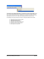
Introduction
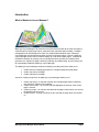
What Is MapLogic Layout Manager?
MapLogic Layout Manager is an extension to ArcGIS which provides all the tools necessary to
create and print multiple page layouts, map series and map books within ArcMap. ArcMap’s
cartographic tools were designed to create very sophisticated individual maps. MapLogic
Layout Manager was designed around the concept of multi-page maps. However, MapLogic
Layout Manager does much more than breaking up a map onto multiple pages. It handles all
the details necessary for creating a true multi-page document just like your standard word
processor will. Options like page numbering, indexing, two-sided printing, print previewing are
all automatically handled by MapLogic Layout Manager.
The MapLogic Layout Manager enhances ArcMap by providing tools which allow you to:
1. Create and store multiple page layouts in a single ArcMap document (Mxd)
2. Create map series in ArcMap
3. Create map books in ArcMap
As part of creating a map book, the MapLogic Layout Manager allows you to:
1. Create map series – a map that is broken into multiple pages based on different
map extents or different layer visibilities
2. Create locator maps – an overview map that highlights the location of the current
page in a series
3. Create key maps – an overview map that lists the page number where you can see
the detailed map of an area
4. Create indexes – a listing of features on the map and the page where are located
on
MapLogic Layout Manager User’s Manual
Page 1
MapLogic Layout Manager User Interface
Everything you need to get to in order to use the MapLogic Layout Manager extension is in one
of three locations:
The “MapLogic Layout Manager” toolbar
The “Layouts” dockable window
The properties of different layout elements and data frames
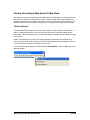
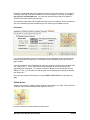
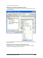
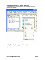
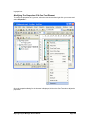
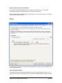
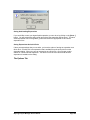
The MapLogic Layout Manager Toolbar
The MapLogic Layout Manager toolbar is a new toolbar that is added to ArcMap by the
extension. Within this toolbar you will find all of the tools needed to put together a map book. If
the toolbar is not visible after you install the extension go to Customize > Toolbars > MapLogic
Layout Manager on ArcMap’s Main Menu to display the toolbar.
MapLogic Layout Manager User’s Manual
Page 2
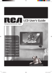
The above diagram shows the toolbar and all of its sub-menus. You will notice that the toolbar
layout is very similar to ArcMap’s Main Menu. This will enable you to quickly find the right
commands in the extension based on where you would expect to find similar commands in
ArcMap.
Different commands in the toolbar are enabled and disabled based on:
1. What kind of layout is currently active (page layout, map series layout or book
layout)
2. What kind of element is currently selected in the layout
3. What kind of MapLogic Layout Manager license you have (Viewer, Basic,
Advanced or Pro)
MapLogic Layout Manager User’s Manual
Page 3
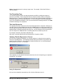
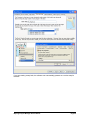
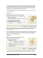
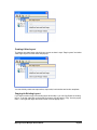
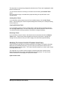
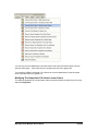
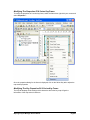
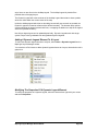
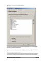
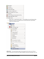
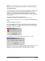
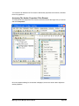
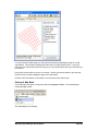
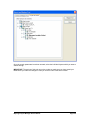
The Layouts Dockable Window
The Layouts is a new dockable window that is added to the ArcMap by MapLogic Layout
Manager. If the Layouts window is not visible after you install the extension, you can make it
visible by selecting View > Layouts Table of Contents… on the MapLogic Layout Manager
toolbar.
This window is where you move around the different layouts contained in the Mxd. Doubleclicking on any layout will activate it (make it visible). You can only have one layout active at
any time.
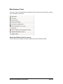
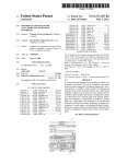
Click on any item listed in the Layouts window using your right-mouse button and you will see a
menu of things you can do with that item. The above diagram shows all the different popup
menus for the different kinds of items contained in the layouts table of contents.
This is where you will do most of the work of managing layouts, map series and map books
(adding/removing new books and layouts, changing the order of sections, etc.). Different
commands on these menus are enabled and disabled based on what kind of MapLogic Layout
Manager license you have (Viewer, Basic, Advanced or Pro).
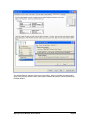
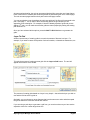
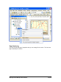
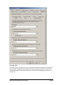
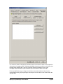
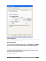
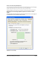
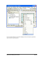
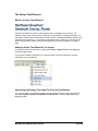
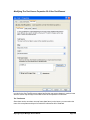
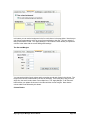
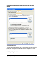
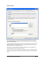
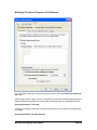
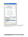
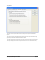
Element Properties
When you insert a new MapLogic Layout Manager element (for example a, Map Series Frame),
the element is added to the active page layout just as in ArcMap’s Insert Menu. To set the
properties of the element, select it, click the right mouse button and then select “Properties…”
on the popup menu. You can also double-click on the element.
MapLogic Layout Manager User’s Manual
Page 4
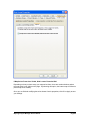
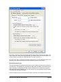
The above example displays the properties of a map series frame. You will notice that the
element will have all the normal properties you would expect for that type of element with an
added tab for properties specific to our extension. Modify the element properties just like you
would with any other element in ArcMap.
MapLogic Layout Manager User’s Manual
Page 5
Before You Get Started
It is very important that the user understand that a map book is a much more sophisticated and,
therefore, more complicated document when compared to a single page layout. If you are not
comfortable about how to use the extension, you will save a great deal of time by reviewing the
Getting Started With MapLogic Layout Manager document. We would also suggest reading the
next section which details the conceptual framework for setting up a map book.
You will also save time by planning the design of your map book before you start creating one.
Simple choices like the page size and margins you select for your map book will affect every
page of your map book. How you choose to break apart your map onto multiple sheets of your
map book will affect the scale and detail visible on each page.
So, even though you might want to create some quick map books just to figure out how
MapLogic Layout Manager works, when it comes to creating a final product a little planning
before hand can save you a lot of time.
Finally, as many of you have already figured out, GIS requires considerable computing power.
Every time you flip the page on a map book, MapLogic Layout Manager has to perform a
number of very intensive manipulations to render the page. Remember this when choosing the
computer you are going to use for your work.
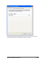
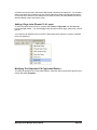
How MapLogic Layout Manager Changes The ArcMap Document
The extension adds a container to the ArcMap document (Mxd) where it holds layouts, map
series and map books. The contents of this container are displayed in a new dockable window
called Layouts.
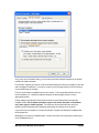
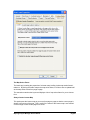
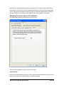
Can a user who does not have the MapLogic Layout Manager extension open an ArcMap
document that has been modified by the extension?
Yes. We have designed the extension so that it will allow the Mxd to be opened on other
copies of ArcMap whether the extension is present or not.
What will ArcGIS users who don’t have the MapLogic Layout Manager extension see
when they open an ArcMap document modified by the extension?
The user will see the layout that was active when the ArcMap document was last saved.
However, keep in mind that the MapLogic Layout Manager has a free “Viewer” license level,
which allows the user to move around the layouts and preview (but not print) map books.
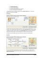
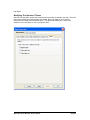
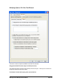
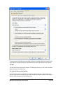
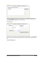
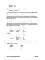
Different Licenses For The MapLogic Layout Manager
The MapLogic Layout Manager has four different license levels: Viewer, Basic, Advanced and
Pro. Depending on the license level that you have purchased, you will have different tools and
capabilities available to you. The following table will give you a quick overview of what you can
do at each license level. Don’t worry if you aren’t sure what some of the items listed in the table
mean, as we will provide plenty of explanation as we get further into the book.
MapLogic Layout Manager User’s Manual
Page 6
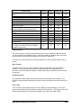
License Level:
View different Layouts in ArcMap document
(Mxd)
Preview map series and map books
Print single layouts
Print maps series and map books
Create/edit layouts and map series
Create/edit map books
Create location listings in map books (i.e.
Main street, page 1)
Anchor elements to specific locations on the
Layout (including two-sided page setups)
Create multi-column location listings in map
books
Geo-Text elements
Dynamic legends
Create automatic detail maps
Create advanced legend labels
Create multi-layout/multi-layer location listings
in map books
Create multi-template sections in map books
(i.e. Page 9 in a map series uses a different
template from the rest)
Viewer
Basic
Advanced
Pro
Yes
Yes
Yes
Yes
Yes
Yes
No
No
No
Yes
Yes
Yes
Yes
No
Yes
Yes
Yes
Yes
Yes
Yes
Yes
Yes
Yes
Yes
No
No
Yes
Yes
No
Yes
Yes
Yes
No
No
No
Yes
No
No
No
No
No
No
No
No
No
No
No
No
Yes
Yes
Yes
Yes
No
No
No
Yes
No
No
No
Yes
Viewer License
The Viewer license is a free license which allows other users to explore the different layouts
you have placed in the ArcMap document. Users can activate the different page, series and
book layouts as well as preview the pages of a map book or map series.
The user can’t create, modify, print or export map series or map book layouts with a Viewer
license.
Basic License
The Basic license gives the user the ability to create new page and map series layouts in
ArcMap. The user can also print map books created by other users using this license.
However, none of the map book creation or editing functionality is available to the user at this
license level.
Advanced License
The Advanced license enables most of the map book functionality for the extension. This
includes creating, editing and printing map books as well as indexing the feature locations in a
book.
Pro License
The Pro license is the highest license level of the MapLogic Layout Manager. At this level,
users have the ability to create multi-layout sections in the map book. This allows you to create
different page layouts for the odd and even pages in the map for two-sided printing.
MapLogic Layout Manager User’s Manual
Page 7
The Pro license user can also create multi-column indexes. For example, if you would like to
create an index that show the location of roads in a map book as well as the location of each
address range in that road, a Pro license is required.
MapLogic Layout Manager User’s Manual
Page 8
Basic Concepts
In this section, we attempt to familiarize the user with the conceptual framework of MapLogic
Layout Manager. Spending a few minutes to review this section will help you greatly in
understanding how MapLogic Layout Manager works. We assume that the user has a working
knowledge of ArcMap Views and Layouts.
Multiple Layouts Within The ArcMap Document
Before you installed the MapLogic Layout Manager, your ArcMap document was a single layout
document. In other words, you were always working on a single printed map called a page
layout. After installing the extension, your ArcMap document is a multi-layout document. You
are no longer limited to a single layout in your ArcMap document (Mxd).
Also, we have added two new types of layouts to the document; the map series layout and the
book layout. A map series layout is very similar to a regular layout except that it generates
multiple pages at print time.
A map book layout is basically a collection of page layouts and map series layouts that are
linked together in a single book. The key is that the items in a map book are linked. The
different parts of a book are aware of each other and update themselves when something
changes.
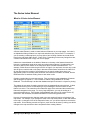
The Map Series Layout
As we mentioned earlier, a map series layout generates multiple pages at print time. A map
series knows how to move the visible area of the map from one area to the next or to turn
MapLogic Layout Manager User’s Manual
Page 9
different layers on and off for each page in the series.
The ability of a map series layout to update the visible area of the map is due to the fact that
one or more of the Data Frames (map windows) in the layout is a Map Series Frame or a
Thematic Series Frame. Map series frames and thematic series frames are new kinds of data
frames that you can add to your layout once you’ve installed the MapLogic Layout Manager.
The Map Series Frame Index Layer
The number and order of pages in a map series frame and the location of each page is based
on a layer in the map called an Index Layer. The Index Layer is a polygon (area) layer in your
map where each polygon represents a page in your map series.
Here are some characteristics about an Index Layer:
-
-
It must be a polygon layer.
The polygons don’t have to be rectangles. For example, you can use the boundary
of each state as the Index Layer for an atlas of the United States. However,
rectangular indexes often provide the best results.
The polygons don’t have to be the same size or the same shape.
Not every polygon in the layer has to be a page in the map book.
The layer need not be turned on; it just needs to be present in your map’s table of
contents.
The number of polygons in the Index Layer determines the number of pages in the series. If
the layer has a definition query (see ArcMap Help for more information), then only those
polygons that meet the conditions of the query are considered.
The MapLogic Layout Manager can use any polygon layer as an Index Layer.
The Map Book Layout
Just as a map series layout is an extension of a page layout, the map book layout is an
extension of map series layouts.
A Map Book Document Can Have Multiple Sections
The first difference you will notice between a map book layout and any other layout is that a
map book can have multiple sections. A section is a group of pages in the map book which
display similar content. For example, if you are creating a road map book you might have a
section containing the individual sheets of the map, while another section might contain an
index of road names and the pages they appear on.
The location of any section in the map book determines the order in which it is printed and the
page numbers that are assigned to it. MapLogic Layout Manager prints the map book from top
down, so the very first page of the top most section in the list is page 1. Right-clicking on the
name of a section in the map book provides the user with some tools to rearrange the sections
as needed.
A Section Can Have Single Or Multiple Pages
Depending on the content of a section, it can have one or more pages. You define the contents
of a section by creating one or more templates for that section and MapLogic Layout Manager
handles the rest of the pages. For example, if your road map is going to be broken up over 20
sheets, you will set up the first sheet (its scale, grid style, etc.) and MapLogic Layout Manager
will take care of the other 19 pages.
MapLogic Layout Manager User’s Manual
Page 10
A Section Can Have Multiple Layouts (Pro License Required)
One important tool available to Pro license users is the ability to have multiple layouts for a
section. For example, suppose you would like to have different layouts for the odd and even
pages on the map. You can achieve this by inserting a new layout into the section and then
setting the section properties to alternate back and forth between the two layouts.
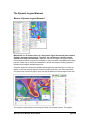
New Elements You Can Add To Map Series And Book Layouts
Earlier we mentioned the map series frame, which is a new element you can add to a layout to
make it print over multiple pages. The MapLogic Layout Manager makes a number of new
elements available to you when creating map series and books.
The above sample shows just a few examples of the types of elements you can add to a layout.
Each element has its own purpose and properties. Each element knows how to update itself
based on its properties, which is what makes the extension so powerful.
A Map Series Frame Breaks A Map Onto Multiple Pages Based On Different Map Extents
MapLogic Layout Manager User’s Manual
Page 11
A map series frame is how you display areas of the map in a map series (similar to a data
frame). However, unlike a data frame, a map series frame knows how to break the map onto
multiple pages using the contents of a special polygon layer called the index layer. For
example if your index layer is breaking your map into 20 pages, the map series frame will make
the layout 20 pages long.
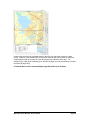
A Thematic Series Frame Creates Multiple Pages Based On Layer Visibility
MapLogic Layout Manager User’s Manual
Page 12
A thematic series frame is how you display different map themes (similar to a data frame).
However, unlike a data frame, a thematic series frame knows how to create multiple pages
using different layer themes that you setup for the map. For example, if you want to create a
land use and a zoning map, you create two themes one of which turns on all the layers
appropriate for a land use map, another which turns on all the layers appropriate for the zoning
map.
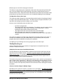
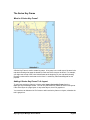
A Series Locator Frame Shows Which Page Is Currently Being Displayed
A series locator frame shows you which part of the overall map is being displayed on the
current page. For example, if you create a map book of U.S. States, you might want a small
map of the entire United States on each page highlighting the location of the state that is
currently being displayed. A series locator frame is designed for this purpose.
MapLogic Layout Manager User’s Manual
Page 13
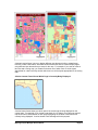
A Series Key Frame Shows The Page Number Of The Pages In A Map Series Frame
A Series Key Frame is used to create key maps. For example, you might want a map of the
entire United States at the beginning of your map book showing the page number where each
state can be found. A Series Key Frame was designed for this purpose.
A Detail Frame Will Generate Automated Detail Maps For The Map
MapLogic Layout Manager User’s Manual
Page 14
A Detail Frame is an area set aside on the layout for detail maps. Detail maps are created
based on a user-selected layer. As the map moves from page to page, the detail frame will
examine the layout to see if features from the selected layer are present on the visible extent of
the map and automatically generate detail maps highlighting the location of the features.
A Dynamic Legend Element Displays Legend Items For The Visible Extent Of The Map
A Dynamic Legend will compare the ArcMap legend against the features that are currently on
display on the map and only display the legend symbols pertaining to the visible map extent.
As a map series moves from page to page, the legend updates to reflect changes on the map.
MapLogic Layout Manager User’s Manual
Page 15
A Series Text Element Creates Text That Changes From Page To Page
A Series Text Element is used to create dynamic text on the pages of a map book. For
example, if each page of a map book is showing a unique Section, Township And Range, you
may want to create a text box that shows what the Section, Township And Range values are on
each page of the map book. If you have this information in your Index Layer, you can use the
Series Text Element to create a text box that dynamically lists this information from page to
page.
A Geo-Text Element Creates Text Based On The Attributes Of A Selected Layer
Geo-Text is similar to the Series Text element in the sense that the text element gets refreshed
as you move from page to page in a series. However, unlike the Series Text which could only
extract information from the attribute table of the Index Layer (grid layer), the Geo-Text element
can extract information from any layer’s attribute table.
For example, if the map series moves over a number of different municipalities and you would
like a label on your map layout showing the name of the municipality you are currently on. With
the Geo-Text element you can link the text label to the municipality layer and extract the name
and place it as a label on the page layout.
A Page Index Element Indexes The Contents Of The Current Map Page
MapLogic Layout Manager User’s Manual
Page 16
A Page Index Element is used to create indexes of features on the current map page. For
example, if you are creating a road map book, you may wish to have a listing of where each
road can be found on each page of the map book (for example, Main Street….B4). A Page
Index Element must always be on the same layout as the map.
A Series Index Element Indexes The Contents Of An Entire Section
A Series Index Element is used to create indexes of features on your map pages. For example,
if you are creating a road map book, you may wish to have a listing of where each road can be
found in the map book (for example, Main Street….Page 2 B-4). Depending on how many
listings there are, a Series Index Element can occupy one or more pages.
MapLogic Layout Manager User’s Manual
Page 17
Two-Sided Map Book Setup And Printing
Another basic difference between MapLogic Layout Manager and the rest of ArcMap is the
ability to setup and map book for printing on both sides of a page (Pro license required).
Obviously the number of printers that can print on both sides of a page are not many, and there
are probably no plotters that can print on both sides of your paper. MapLogic Layout Manager
can’t actually send a command to a printer to print something on a page and then flip the page
over and print on the other side of the page. However, it does properly setup your map book so
that you could manually print to both sides of the paper or photocopy onto both sides of a page.
You do this by setting up two different layouts for a section and then telling the extension to
alternate between the two.
Where To Go From Here?
This section has provided you with a basic overview of the conceptual framework for the
MapLogic Layout Manager and some key capabilities and features as well as some important
information about using the software’s user interface. Hopefully, the user will have an overall
understanding of how things are organized in MapLogic Layout Manager and the basic
components of map series and books. In the following sections we will provide much more
detailed instructions on how to setup, customize and print page, series and book layouts.
Keep in mind that this is not a tutorial. If you would like step by step instructions on setting up
map series and books, please refer to the Getting Started With MapLogic Layout Manager
document.
MapLogic Layout Manager User’s Manual
Page 18
Working With Expressions
One of the key features of the MapLogic Layout Manager is that no text label in a map series or
map book is ever hardwired. Whether the label is a page number, a page title, a listing in a
series index, or any other text item in the map book, you determine the contents of that label by
composing an expression for it.
Why use an expression? Well this allows you to have total control over what the label says.
For example, by default the adjacent page label expression is “See Page
$$ADJACENT_PAGE_NUMBER”. The actual label might look like “See Page 3”. Suppose
you prefer the label to say “Go To 3”. All you would need to do is to change the expression to
say “Go To $$ADJACENT_PAGE_NUMBER”.
Although there is a default expression for every text label that the extension creates, you will
probably want to learn how to modify these labels to best meet your requirements.
All expressions are created using the MapLogic Expression Builder Dialog. Whenever you see
a label expression on any of our dialogs, you will see an Expression button next to it which
brings up the expression builder dialog.
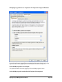
The MapLogic Expression Builder Dialog
MapLogic Layout Manager User’s Manual
Page 19
The Expression dialog lets you build an expression from which a label is created. This dialog is
divided into four areas:
1.
2.
3.
4.
The reserved words
The database fields and field formatting statements
The text formatting tags
The expression
The label expression is a coded by combining reserved words, database fields, formatting
statements and other text into a statement which the tool can understand. Fortunately the
coding rules are very simple and the tool does most of the work for you.
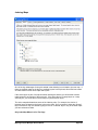
Reserved Words
Anytime you see an item in an expression that starts with $$, you are looking at a reserved
word. A reserved word is a word that the extension understands and substitutes for an
appropriate value. For example, “See Page $$ADJACENT_PAGE_NUMBER” will be translated
into a label that might look like “See Page 3”.
Depending on what item you are creating an expression for, different reserved words will be
presented to you to choose from. Select a reserved word from the list, and a short description
of the meaning of the word will appear below it.
MapLogic Layout Manager User’s Manual
Page 20
The following is a list of available reserved words:
General
$$BOOK_NAME – The name assigned to a map book
$$BOOK_PAGE_COUNT – The total number of pages in a map book
$$DATE – Today’s date formatted according to your computer’s default date format
$$DATE_LONG – Today’s date formatted according to your computer’s long date format
$$DATE_MEDIUM – Today’s date formatted according to your computer’s medium date format
$$DATE_SHORT – Today’s date formatted according to your computer’s short date format
$$PAGE_NUMBER – Current page number
$$PROJECT_DRIVE – The drive letter where the MXD is located
$$PROJECT_NAME – The MXD file name
$$PROJECT_FULLNAME – The MXD file name and full path to where its located
$$PROJECT_PATH – The full path name to where the MXD is located
$$SECTION_NAME – The name assigned to the current section
$$SECTION_PAGE_COUNT – The total number of pages in the current section
$$TEMPLATE_NAME - The name assigned to the current template layout
$$TEMPLATE_PAGE_COUNT - The total number of pages in the current template layout
$$TIME_LONG – Current time formatted according to your computer’s long time format
$$TIME_MEDIUM – Current time formatted according to your computer’s medium time format
$$TIME_SHORT – Current time formatted according to your computer’s short time format
Indexing Location Of Features In Map Series
$$CENTERX – The X coordinate of the center point of the feature being indexed
$$CENTERY – The Y coordinate of the center point of the feature being indexed
$$FRAME_NAME – The name of the map series frame being indexed
Map Series Frames
$$ADJACENT_PAGE_NUMBER – The page number of the page adjacent to the current page
$$ADJACENT_PAGE_TOP – The page adjacent to the top edge of the current page
$$ADJACENT_PAGE_BOTTOM – The page adjacent to the bottom edge of the current page
$$ADJACENT_PAGE_LEFT – The page adjacent to the left edge of the current page
$$ADJACENT_PAGE_RIGHT – The page adjacent to the right edge of the current page
$$ADJACENT_PAGE_TOP_LEFT – The page adjacent to the top left corner of the current
page
$$ADJACENT_PAGE_TOP_RIGHT – The page adjacent to the top right corner of the current
page
$$ADJACENT_PAGE_BOTTOM_LEFT – The page adjacent to the bottom right corner of the
current page
$$ADJACENT_PAGE_BOTTOM_RIGHT – The page adjacent to the bottom left corner of the
current page
$$ADJACENT_PAGE_TOP_ALL – All pages adjacent to the top edge of the current page
$$ADJACENT_PAGE_BOTTOM_ALL – All pages adjacent to the bottom edge of the current
page
$$ADJACENT_PAGE_LEFT_ALL – All pages adjacent to the left edge of the current page
$$ADJACENT_PAGE_RIGHT_ALL – All pages adjacent to the right edge of the current page
$$ADJACENT_PAGE_ALL – All pages adjacent to the current page on all sides
Page Index and Series Index
$$COLUMN – The frame’s grid column location of the feature being indexed
$$DOTS – Expand the text in a column to the column width using dots (i.e. Main St……….Pg 3)
$$ROW – The frame’s grid row location of the feature being indexed
MapLogic Layout Manager User’s Manual
Page 21
Series Text
$$FIRST_3CHAR – First 3 characters of first listing on current page (must be linked to series
index)
$$FIRST_CHAR – First character of first listing on current page (must be linked to series index)
$$FIRST_LISTING –listing on current page (must be linked to series index)
$$FIRST_WORD – First word of first listing on current page (must be linked to series index)
$$LAST_3CHAR – First 3 characters of last listing on current page (must be linked to series
index)
$$LAST_CHAR – First character of last listing on current page (must be linked to series index)
$$LAST_LISTING – Last listing on current page (must be linked to series index)
$$LAST_WORD – First word of last listing on current page (must be linked to series index)
Geo-Text
$$MAPX – Geo-Text query point’s X coordinate (in map units)
$$MAPY – Geo-Text query point’s Y coordinate (in map units)
Thematic Series Frames
$$THEME_NAME – The name of the currently active theme
$$CUSTOM_TEXT_1 – Active theme’s custom text 1
$$CUSTOM_TEXT_2 – Active theme’s custom text 2
$$CUSTOM_TEXT_3 – Active theme’s custom text 3
$$CUSTOM_TEXT_4 – Active theme’s custom text 4
Detail Frames
$$DETAIL_NUMBER – The number of the current detail map
If there are no reserved words available for an expression, the area is grayed out.
You can add a reserved word to your expression by selecting it and clicking the Add button.
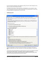
Database Fields
The database fields area displays all the available database fields for the expression you are
building. It is the information from these fields that are extracted and placed in the text label.
Geometry (shape) and Blob fields cannot be used in a label expression.
Database field names are always enclosed in square brackets “[ ]”. For example, a field called
"State_Name" would be written as [State_Name].
You can add a field to the label expression by selecting it and clicking the Add button. If there
are no database fields available for an expression, the area is grayed out.
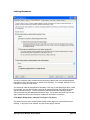
Formatting Statements
Formatting statements allow you to modify the information extracted from database fields. For
example, you might want to round a numeric value, or change text to upper case, or change the
way a date is displayed.
Select any formatting statement from the list and a short description will appear on the dialog
explaining what the statement does.
MapLogic Layout Manager User’s Manual
Page 22
After you have selected a formatting statement, click Add to add the formatting to the
expression. The tool will make sure the information is added using the correct expression
coding syntax.
For example:
[Population1990].Round(0)
A formatting statement that is mismatched with the field type is ignored. For example, if you
attempt to change the number of decimals on a text field, it will be ignored.
Formatting statements are added after the field with only a "." between the two (for example,
[State_Name].UCase).
You can apply multiple formatting statements to a field by adding them one after the other.
Formatting statements will be applied to the value of the field starting from the left and moving
to the right. For example, [State_Name].UCase.LCase will result in a lower case label because
the LCase statement was the last formatting statement.
Some examples of formatting statements are:
Using the layer: US States
Using the legend label text definition: [State_Name].UCase
Would result in the following label in your legend for the state of Florida: FLORIDA
Using the layer: US States
Using the legend label text definition: [State_Name].Replace("A","IAN").UCase
Would result in the following label in your legend for the state of Florida: FLORIDIAN
The following is a list of all available formatting statements:
Abs - Absolute value of a number. For example: -3.Abs = 3
FormatCurrency - Number formatted to system currency. For example: 100.FormatCurrency =
$100.00
Format(Instructions) - The Format function converts a value to a text string and gives you
control over the string's appearance. For example, you can specify the number of decimal
places for a numeric value, leading or trailing zeros, currency formats, and portions of the date.
Format is a very powerful statement and can do many different things.
The instructions for the Format statement can be one of many named formats or a user defined
instruction.
Named Formats:
General Number - Shows numbers as entered.
Currency - Shows negative numbers inside parentheses.
Fixed - Shows at least one digit.
Standard - Uses a thousands separator.
Percent - Multiplies the value by 100 with a percent sign at the end.
Scientific - Uses standard scientific notation.
General Date - Shows date and time if expression contains both. If expression is only a
date or a time, the missing information is not displayed.
Long Date - Uses the Long Date format specified in the Regional Settings dialog box of
the Microsoft Windows Control Panel.
Medium Date - Uses the dd-mmm-yy format (for example, 03-Apr-93)
Short Date - Uses the Short Date format specified in the Regional Settings dialog box
MapLogic Layout Manager User’s Manual
Page 23
of the Windows Control Panel.
Long Time - Shows the hour, minute, second, and "AM" or "PM" using the h:mm:ss
format.
Medium Time - Shows the hour, minute, and "AM" or "PM" using the "hh:mm AM/PM"
format.
Short Time - Shows the hour and minute using the hh:mm format.
Yes/No - Any nonzero numeric value (usually - 1) is Yes. Zero is No.
True/False - Any nonzero numeric value (usually - 1) is True. Zero is False.
On/Off - Any nonzero numeric value (usually - 1) is On. Zero is Off.
Beyond the named formats, you can also create custom formats using syntax that the Format
statement understands. The following examples of user defined formats assume that the
country in the Windows Control Panel is set to "English (United States)."
Format("00000.00") will result in a number like 08315.40
Format("#####.##") will result in a number like 8315.4
Format("##,##0.00") will result in a number like 8,315.40
Format("$##0.00") will result in a number like $315.40
Format("0.00%") will result in a number like 700.00%
Format("m/d/yy") will result in a date like 1/27/93
Format("dddd, mmmm dd, yyyy") will result in a date like Wednesday, January 27, 1993
The Format statement is based on the Visual Basic Format function and can do many things.
For more information on how Format works, visit the Microsoft website for this function at:
http://msdn.microsoft.com/library/default.asp?url=/library/en-us/vblr7/html/vafctformat.asp
FormatNumber(0) - Sets number of decimal places for a numeric value. For example:
2.53.FormatNumber(4) = 2.5300
LCase - Sets all characters in a string to lower case. For example: "Hello World".LCase =
"hello world"
Left(0) - Returns left x number of characters in a string. For example: "Hello World".Left(2) =
"He"
LTrim - Removes spaces to left of string. For example: " Hello World".LTrim = "Hello World"
Mid(0,0) - Returns the middle x number of characters at position y. For example: "Hello
World".Mid(7,3) = "Wor"
Replace(Search,Replace) – Search and replace text in a string. For example: "Hello
World".Replace(o,xx) = "Hellxx Wxxrld"
Right(0) - Returns the right x number of characters. For example: "Hello World".Right(2) = "ld"
Round(0) - Rounds a number to decimal x places. For example: 2.67.Round(0) = 3
RTrim - Removes spaces to right of a string. For example: "Hello World
World"
".RTrim = "Hello
Spaces(0) - Inserts spaces between characters of a string. For example: "GIS".Spaces(3) = "G
I S"
Trim - Removes spaces from both sides of a string. For example: " Hello World
"Hello World"
MapLogic Layout Manager User’s Manual
".Trim =
Page 24
UCase - Sets all characters in a string to upper case. For example: "Hello World".UCase =
"HELLO WORLD"
Text Formatting Tags
Text formatting tags are HTML–like tags supported by ArcGIS for modifying text styles of
portions of your labels. These change the text font, whether its bold or italics, the character
spacing and so on. Select any formatting tag from the list and a short description will appear on
the dialog explaining what the statement does. For more information on text formatting tags,
refer to your ArcMap documentation. After you have selected a formatting statement, click Add
to add the formatting to the expression.
The Label Expression
The expression text box is where the code for the label expression is composed. Although you
can select items from the available lists and click the Add buttons to create the expression, you
can also type the expression directly in this text box. An expression is composed by combining
database fields, formatting statements and other text. Any text entered in the text box that the
tool can’t interpret as a database field or formatting statement is treated as plain text.
For example: Population: [Population1990].Round(0)
Will result in a symbol label that will look something like: Population 874923
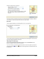
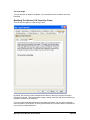
Verifying That An Expression Is Correct
Once you have created an expression, you can test whether it is using the correct syntax by
clicking on the Verify button. The Expression Builder dialog will examine the expression and
prompt you with a response. If the expression contains a syntax error, you will be prompted
with the nature of the error. For example,
If the expression is valid, detailed information about how the tool is interpreting your expression
is presented. For example,
Saving The Expression
Once you have created the expression you like, click the OK button to save it.
MapLogic Layout Manager User’s Manual
Page 25
Quickly Generating A Map Series Or Map Book
Generating a map book or map series using MapLogic Layout Manager is a multi-step process
with numerous options and settings at each step. However, MapLogic Layout Manager also
includes a wizard which can create a map series or book with only a few quick selections. The
wizard automates the entire process using the most commonly selected options and settings.
The Book Wizard
The Book Wizard will create a map series or book using the most commonly used options. In
order to create the map series or book you will need to have an index layer loaded into the
active map. This is the polygon layer in which each polygon represents the boundary of a page
in the series.
Keep in mind that there are many more options available in MapLogic Layout Manager for
every step of the book creation process. The Book Wizard also includes information on how to
access the options available on each step of the process.
You can open the Book Wizard by selecting Tools > Book Wizard… from the MapLogic Layout
Manager toolbar.
MapLogic Layout Manager User’s Manual
Page 26
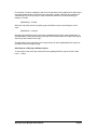
The Book Wizard dialog is designed to make the process of creating a map book or map series
quick and easy by including extensive help and visuals.
MapLogic Layout Manager User’s Manual
Page 27
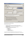
The first option is to choose whether you are creating a map series or a map book. As can be
seen, a map book is a map series that also includes an overview map and an index of features
(for example a street index). While the map series is available at all license levels, you need an
Advanced or Pro license to generate a map book.
MapLogic Layout Manager User’s Manual
Page 28
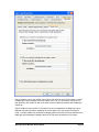
The index layer is necessary to create a map series or book. The polygons in the index layer
will become pages in the series. The sort field determines the order by which the pages are
added to the series.
MapLogic Layout Manager User’s Manual
Page 29
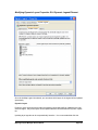
If you are creating a map book, the software can automatically generate an overview map for
the book.
MapLogic Layout Manager User’s Manual
Page 30
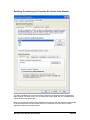
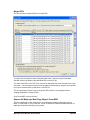
If you are generating a map book, the software can also index a layer and add a table to the
end of the book listing the location of features in the book. A street index is the most commonly
generated index. In order to create an index, you will need to select a layer to index and the
field from that layer to include in the index.
As part of the indexing process, the software needs to store its results in a database which will
later be used to generate the table. Use the folder tool to select a destination for the index
database.
MapLogic Layout Manager User’s Manual
Page 31
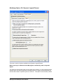
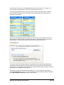
The wizard offers two options for the layout of the index. Keep in mind that, as with all other
steps in the process, there are many more options available beyond the choices presented by
the Book Wizard.
MapLogic Layout Manager User’s Manual
Page 32
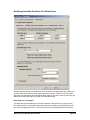
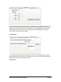
Once you have selected all the necessary options on the book wizard, click the Create Map
Book button to generate the map series or book. The summery window will update you as
each step in the process is completed.
MapLogic Layout Manager User’s Manual
Page 33
Creating Map Series Index Layers
The ability of MapLogic Layout Manager to create a map series is based on the Index Layer.
As we mentioned earlier, the Index Layer is a polygon layer that contains all the information
needed to break the map apart into multiple pages. Essentially, polygons within your Index
Layer represent pages on your map book.
The MapLogic Layout Manager can use any polygon layer as an Index Layer. The extension
provides you with a wizard that creates grid and linear index layers for you. If the tools provided
by the extension don’t meet your requirements, you can always create your own Index Layer
using the layer creation and editing tools provided by ArcMap.
The Grid Wizard
The Grid Wizard provides tools which allow you use a number of different methods to generate
a grid layer. Grids can cover an area, follow a line, follow the extent of map features or even
entered manually. Additionally, the resulting grids can be edited, moved, merged or split. You
can preview your results on the map before committing the grids to a shapefile or feature class.
Grid an Area
Follow a Line
Map Feature Extents
You can create a grid index layer by selecting Tools > Grid Wizard… from the MapLogic
Layout Manager toolbar.
The process of creating an Index Layer using the Grid Wizard is to use one or more of the grid
tools available on the wizard to populate the Grid List. The grid list is essentially a list of
rectangles. For each rectangle there is a set size and position and, optionally, a name, scale
and rotation.
MapLogic Layout Manager User’s Manual
Page 34
Grid An Area
The most common type of grid used in a map series is to take a large area and split it into
uniform smaller pieces.
The Grid an Area tool can be used to easily generate this type of grid. In order to create the
grid the software needs to know:
MapLogic Layout Manager User’s Manual
Page 35
1.
2.
3.
4.
5.
The extent of the grid
The size of each grid cell
The order of the grid cells
Rules for limiting grid placement (optional)
Rules for naming grid cells (optional)
To begin the process of creating an area grid click the Grid an Area button. The tool will
appear at the bottom of the wizard.
Grid Extent
The grid extent is the limit of the area for which you want to create a grid index layer for. You
can type in the coordinate limits of the extent, click on the Full Extent button to select the area
covered by all layers in the map, click on the Current Extent button to select the area of the
map that is currently visible or use the rectangle tool to draw the extent on the map.
By default the current visible extent of the active map is selected for the grid extent.
Grid Size
Once you have determined the area you are going to make a grid for, you need to tell the
wizard what the size of each grid cell should be. You can set the cell size automatically or in
page units or map units.
MapLogic Layout Manager User’s Manual
Page 36
To set the size automatically, you set how many rows and columns the area is to be divided
into.
To set the cell size in page units, you must tell the wizard at what scale you will be printing the
map series and how big you want each cell to be on the printed page. This is the preferred
method of creating a grid since you generally want to print a map series at a particular scale.
The default values for the cell width and height is the current size of the frame on the layout.
This option is only available with projected coordinate systems.
To set the cell size in map units, you must tell the wizard how big an area you want each grid
cell to cover on the map.
By default the area is split into a 10 by 10 grid.
Grid Order
The grid order is the order in which the grid cells will be added to the grid list. When creating a
map series there is usually a preferred order in which the pages will flow in the series.
By default the order are the pages are from the upper left corner of the map to the lower right
corner.
Grid Limits
MapLogic Layout Manager User’s Manual
Page 37
By default a rectangular grid will be created covering the entire extent entered. If you want to
create grid cells only where there is data from one or more layers in your map, check Only
place grid if it overlaps data from. You must then select the layers which you want the
wizard to check while creating the grid cells.
The wizard will check each grid cell against the layers you have selected. If there is data from
one of the selected layers that overlaps the grid cell, then the grid is added to the list.
Grid Names
You can optionally assign a name to each page in the grid cell based on the row and column
location of the cell in the index grid. These names can be displayed on the map in place of
page numbers.
You can set whether or not the software should name grids as if the first grid is assumed to be
row 1 and column 1. This is useful if there are already grids in the grid list and you are
appending to the existing list. For example, if there are already 4 rows of grids and you are
adding a 5th row, you can make sure that the grids are named properly by setting the starting
row number to 5.
Once you have selected all the options, press the Add To Grid List button to generate the
grids.
Follow A Line
Another common way of creating grids is to follow a linear feature on a map. This is useful for
creating a map series that follows a road alignment, river, etc.
In order to create the grid the software needs to know:
MapLogic Layout Manager User’s Manual
Page 38
1.
2.
3.
4.
The grid path
The size of each grid cell
Rules for grid placement
Rules for naming grid cells (optional)
To begin the process of creating an area grid click the Follow a Line button. The tool will
appear at the bottom of the wizard.
Grid Path
The grid path consists of one or more lines along which the software will place grid cells. The
path can be drawn on the map, imported from an existing graphic line on the map or imported
from a linear feature layer.
If the lines are being imported from a layer, you have the option of importing all line features or
just the selected features. The direction of the line features is important as the software will
begin at the starting node of the line and move to the ending node.
Grid Size
Once you have determined the path to make a grid for, you need to tell the wizard what the size
of each grid cell should be. You can set the cell in page units or map units.
MapLogic Layout Manager User’s Manual
Page 39
To set the cell size in page units, you must tell the wizard at what scale you will be printing the
map series and how big you want each cell to be on the printed page. This is the preferred
method of creating a grid since you generally want to print a map series at a particular scale.
The default values for the cell width and height is the current size of the frame on the layout.
This option is only available with projected coordinate systems.
To set the cell size in map units, you must tell the wizard how big an area you want each grid
cell to cover on the map.
Grid Placement
Grids that follow linear features can either maintain a horizontal orientation or rotate in line with
the direction of the path they are following. Rotating grids try to keep the linear feature
centered on the page.
Another placement option relates to the position of the starting grid. The first grid can either be
centered on the starting point of the linear feature or placed so the line starts at the edge of the
page. If you choose the start at edge option, you can set an offset so there is a small gap
between the edge of the page and the line.
Grid Names
You can optionally assign a name to each page in the grid cell based on the path and page
number of the grid. These names can be displayed on the map in place of page numbers.
MapLogic Layout Manager User’s Manual
Page 40
As was mentioned earlier, the tool can generate grids that follow more than one linear feature.
Each of these lines is called a path and each grid that is placed along the line is called a page.
The tool can name pages based on their path number and page number.
You can set whether or not the software should name grids as if the first grid is assumed to be
path 1 and page 1. This is useful if there are already grids in the grid list and you are
appending to the existing list. For example, if there are already 4 paths of grids and you are
adding a 5th path, you can make sure that the grids are named properly by setting the starting
path number to 5.
Once you have selected all the options, press the Add To Grid List button to generate the
grids.
Layer To Grid
Another common way of creating grids is to match the extents of features in a layer. For
example, if you want to create a map series of school locations, or hazardous wastes sites, etc.
To begin the process of creating an area grid click the Layer to Grid button. The tool will
appear at the bottom of the wizard.
The process of creating grids based on a layer is very simple. Just select the layer you wish to
use and the field to sort the grids on.
Optionally, you can choose to merge features that have the same sort value and also expand
the grid so that there is a buffer around each feature.
If you are using a point layer to generate a grid from, you need to make sure you have set the
expansion value to a number larger than zero.
MapLogic Layout Manager User’s Manual
Page 41
Once you have selected all the options, press the Add To Grid List button to generate the
grids.
Single Grid
If none of the automated methods for generating grids is appropriate for what you are trying to
do, you can always generate the grids manually.
To begin the process of creating an area grid click the Single Grid button. The tool will appear
at the bottom of the wizard.
Creating a new grid is very simple. You can either type in the size and position of the grid or
use the rectangle tool to draw the grid on the map.
Optionally, you can define a name, scale and rotation for the grid. The rotation value does not
actually rotate the grid. This value can be used in the map series properties to rotate the entire
map on the page represented by the grid.
If you plan to add more than one grid, check the Keep tool open after adding new grid option.
This will leave the tool open after grid has been added so you can create additional grid cells.
Once you have selected all the options, press the Add To Grid List button to generate the
grids.
Editing Grids
Once you have populated the grid list you have the option of editing, splitting, merging or
moving grid cells using the tools on the wizard
Edit Grid
MapLogic Layout Manager User’s Manual
Page 42
The edit tool allows you to change all of the parameters of an existing grid cell.
To edit a single grid, select the grid on the grid list and press the Edit button.
Split Grid
The split tool allows you to split a grid cell into smaller grids. This is useful when an area of the
map has too much detail and would be better served by multiple pages.
Because the split tool is generating new grid cells, you have options available to determine the
order of the new cells as well as the naming style for the new cells.
Merge Grids
The merge tool is the reverse of the split tool it allows you to merge multiple cells into one. This
is useful when an area of the map is sparse and would be better served by a single page.
MapLogic Layout Manager User’s Manual
Page 43
The merge tool does not maintain the geometry of the individual grids it is replacing. Rather a
new rectangle is created that matches the extent of the replaced grids.
Move Grids
The move grids tool allows you to shift the position of one or more grid cells.
You can either enter the horizontal and vertical offsets for the selected grids or use the line tool
to draw the direction and distance of the move.
Generating The Index Layer
Once you have populated the grid list with the grid cells, click the Create Grids button to
generate a shapefile of feature class from the grid list.
If you are not ready to create the final grid and would like to work on the grid list at a later time,
you can use the save
be loaded later.
and load
buttons to save the grid list to an external file which can
MapLogic Layout Manager User’s Manual
Page 44
Managing Page, Map Series And Book Layouts
As was mentioned previously, the MapLogic Layout Manager allows you to store multiple page,
map series and book layouts within the ArcMap document. You manage the collection of
layouts in the document through the Layouts dockable window.
The Layouts is a new dockable window that is added to the ArcMap by MapLogic Layout
Manager. If the Layouts window is not visible after you install the extension, you can make it
visible by selecting View > Layouts Table of Contents… on the MapLogic Layout Manager
toolbar.
You create, copy/paste, edit, delete, rename and rearrange page layouts, maps series layouts
and book layouts through the Layouts dockable window.
Displaying Popup Menus In The Layouts Dockable Window
Right-clicking on any item in the layouts dockable window will present you with popup a menu
which allows you to manage that item. For a full listing of all the different popup menus, please
refer to the section titled MapLogic Layout Manager User Interface.
MapLogic Layout Manager User’s Manual
Page 45
Creating A New Layout
To create a new page layout right-click your mouse on where it says “Page Layouts” and select
“New Page Layout” from the menu that pops up.
You can similarly create new maps series, map books, book sections and section templates.
Copying An Existing Layout
If you want to make a copy of an existing layout and modify it, you can Copy/Paste an existing
layout. To do this, right-click on the layout you want to copy and select “Copy” from the popup
menu. Then right-click again and select “Paste” from the popup menu.
MapLogic Layout Manager User’s Manual
Page 46
Moving Back And Forth Between Layouts
In order to see the contents of any layout in the ArcMap document you need to activate that
layout. In order to activate a layout, all you need to do is double-click on its name in the list or
right click on its name and select “Activate” from the pop-up menu. This will move the layout
that is currently being displayed to the background and print the new layout to the foreground of
your ArcMap session. The active layout is always displayed in bold letters in the table of
contents along with the word “(Active)” next to its name.
Renaming Layouts
To rename a page, map series or book layout, right-click on a layout and select “Rename…”.
Removing (Deleting) Layouts
If you would like to remove a layout from your ArcMap document, right-click on the layout you
would like to delete and select “Remove…” from the popup menu.
You should know that you can’t “undelete” a deleted layout. The extension will give you a
warning before deleting a layout.
MapLogic Layout Manager User’s Manual
Page 47
Rearranging Layouts
You can always rearrange the positions of a layout in the list of page layouts by right-clicking on
the name of the layout and then going to the “Order” menu.
Rearranging is particularly important when dealing with sections in a map book as the order of
the sections is the order in which they are printed.
Managing Page and Map Series Layout Properties
The properties of a page or map series layout, including its paper size, the location of different
elements on the page, and the properties of those elements are all modified just as you have
done in the past in ArcMap.
Managing Map Book Properties
A map book is a collection of sections. You add and remove contents from a map book by
adding and removing sections. You do this just as you would with layouts by right-clicking on
the name of the book or section in the Layout dockable window.
MapLogic Layout Manager User’s Manual
Page 48
A map book does not have any properties other than the sections it contains.
Each section in a map book can have one or more templates (A Pro license is required to add
multiple templates to a section). A template is a layout which determines the contents of a
section. The reason for having multiple templates in a section is so that you can create
different layouts for different pages in the section.
For example, if you are printing a two-sided map book, you may wish to switch the binding
margin for odd and even pages. Or you may wish to move the page number so that it is always
on the outside edge of the page.
Another example would be a situation where one area of the map is so different from the rest
that you would like to create a different layout for it.
Managing Section Properties
To manage the properties of a section right-click on the section name and select Properties…
from the popup menu.
MapLogic Layout Manager User’s Manual
Page 49
Page Numbering
There are two general types of properties that you can manage for the section. The first is the
page numbering for a section.
MapLogic Layout Manager User’s Manual
Page 50
As you can see in the dialog, the normal behavior of a section is for its page numbering to
continue from the previous section in the book. The MapLogic Layout Manager automatically
keeps track of how many pages exist in each section of the book and numbers the pages
accordingly.
You can, however, override the default page number and set the starting page number of a
section to a particular value. To do this, click the Start at: option and then enter a new page
number.
This is useful if you have pages in your map book which you do not want counted. For
example, the map book might have a cover page layout which wouldn’t normally be counted.
Master And Alternate Templates
If you have a Pro license, a section can have more than one template layout. When there is
more than one template in a section, one of them must be selected as the master template.
MapLogic Layout Manager User’s Manual
Page 51
The master template is the primary template for the section. All other templates modify the
master template by adding or substituting pages in the master template.
MapLogic Layout Manager User’s Manual
Page 52
As you can see in the above dialog, you can select how each alternate template in the section
modifies the master template.
For example, suppose you want to create a two-sided map book where the template for the odd
and even pages are different. Let’s say you want to move the page number so that it’s always
on the outside edge of the page.
First you would create a template layout for the section. Then copy/paste that layout so you
have a duplicate of it. Modify the duplicate template so that the page number is in the
appropriate position.
Finally, display the properties of the section and set the second template as an alternate
template. Select This template substitutes pages in the master template and Substitute
every other page in master template. The extension will now alternate back and forth
between the two templates when displaying and printing the contents of the sections.
If you have only one template in a section the Master Template and Alternate Templates tabs
will be grayed out.
Modifying the contents of templates within a section is the same as modifying any other layout
in the ArcMap document.
MapLogic Layout Manager User’s Manual
Page 53
Where To Go From Here?
In this chapter you have learned the basics of managing (creating, deleting, copy/pasting,
renaming) page, map series and book layouts in the ArcMap document. However, the
MapLogic Layout Manager adds a number of new graphic elements that you can add to your
layout. These graphic elements are what make creating map series and books possible.
In the next chapters we will discuss the details of each of these new graphic elements.
MapLogic Layout Manager User’s Manual
Page 54
The Map Series Frame
What Is A Map Series Frame?
A Map Series Frame is how you display areas of the map in a map series (similar to a data
frame). However, unlike a data frame, a map series frame knows how to break the map onto
multiple pages using the contents of a special polygon layer called the Index Layer. For
example, if your Index Layer is breaking your map into 20 pages, the map series frame will
make the layout 20 pages long.
Adding A Map Series Frame To A Layout
To add a new Map Series Frame to a layout select Insert > Map Series Frame from the
MapLogic Layout Manager toolbar. You can only add map series frames to active map series
and book layouts. If the active layout is a page layout, the tool is grayed out.
You must have a Basic, Advanced or Pro license to add a map series frame to a layout,
otherwise the tool is grayed out.
MapLogic Layout Manager User’s Manual
Page 55
Converting An Existing Data Frame To A Map Series Frame
You can also convert an existing data frame to a map series frame by selecting the data frame
and then selecting Edit > Convert Data Frame To Map Series Frame… from the MapLogic
Layout Manager Toolbar.
You can only convert a data frame to a map series when the active layout is a map series or
book layout. If the active layout is a page layout, the tool is grayed out.
You must have a Basic, Advanced or Pro license to convert a data frame to a map series
MapLogic Layout Manager User’s Manual
Page 56
frame, otherwise the tool is grayed out.
Modifying The Properties Of A Map Series Frame
To modify the properties of a map series frame, select the frame then right-click your mouse
and select Properties…
Once the properties dialog for the frame is displayed, click on the Map Series tab to adjust the
map series properties.
Modifying The Series Properties Of A Map Series Frame
The Series tab displays all the settings which determine how the contents of the map will
change as you move from page to page in a map series.
MapLogic Layout Manager User’s Manual
Page 57
The Index Layer
The Index Layer is a polygon layer in your map that determines the boundaries of each page in
the map series. Essentially, each polygon in the layer represents a page in the map series.
The extension examines the map and presents you with all the valid polygon layers for you to
choose from.
MapLogic Layout Manager User’s Manual
Page 58
The number of polygons in the index layer determines the number of pages in the series. If the
layer has a definition query (see ArcMap Help for more information), then only those polygons
that meet the conditions of the query are considered.
The Series Sort Order
Once you have selected the Index Layer, you have the option of sorting the pages in the layer
based on the value in one of the fields in the layer’s table. To do this check Sort the series
using this field: and then select the appropriate field name from the list.
If you created your Index Layer using one of the extension’s tools, there will be a field named
Pg_Number in your table which contains the page order you specified when the layer was
created.
The Reverse Order option reverses the sort order.
If no sorting option is selected, the order of the page in the series is the order of the features in
the layer’s table.
The Page Name
You have the option of assigning a page name to each page in the map series by selecting a
page name field. The page name does not appear anywhere on the layout itself, rather it is
used to display the names of pages in the Layouts table of contents as well as on the print and
export dialogs. This gives you additional options when selecting pages for display, print or
export.
The Page Rotation
If you would like the pages in your map series to have different angles, you can select a
numeric field from which the page rotation will be read.
If you created a linear index layer using the extension, there will be a field named Pg_Angle in
your table which contains the rotation of each page in your linear index.
The Page Reference Grid
If you would like the reference grid (A1, A2, B1, B2, etc) around the map to change from page
to page in a map series, you can create a field that contains the name of the reference grid for
each page in the series.
As the map series moves from page to page the name of the reference grid is read from the
selected field and the appropriate grid is turned on.
Modifying The Scale Properties Of A Map Series Frame
The Scale tab displays all the settings which determine the map scale properties of each page
in the map series.
MapLogic Layout Manager User’s Manual
Page 59
The Page Extent/Scale
You can set the extent of each page in the map series in one of three ways.
Automatic – This method zooms the boundaries of the map for each page so that the polygon
representing that page “best fits” the frame. If you select this option, you can also set an
amount of overlap between the pages.
The “Round scale to nearest” option will adjust the automatic scaling so that the map scale is a
MapLogic Layout Manager User’s Manual
Page 60
rounded value.
Minimum and Maximum scales set the limits of the automated scaling so the map can not zoom
in or out beyond set limits. Zero indicates that no minimum or maximum scales are set.
Fixed Scale – This method sets the scale of the map to a fixed value for all pages in the map
series. Each page will be centered on the polygon representing that page. If the polygons in
the index layer are of different sizes, the series will ignore the size difference.
Scale Each Page Using Field – This method reads the scale for each page from a numeric field
in the index layer’s table. This is useful if you have specific scales that you want each page of
the map series to be set to.
If you created your index layer using one of the extension’s tools, there will be a field named
Pg_Scale in your table which contains the scale specified when the layer was created.
The Reference Scale
If you would like each page in the map series to have a particular reference scale, you can do
so by selecting a reference scale field. The values from this field in your Index Layer’s table will
be used to update the reference scale of the map as you move from page to page.
Modifying The Adjacent Page Listing Properties Of A Map Series Frame
The Adjacent Page Listings tab displays all the settings which determine the properties of the
labels that appear on the edge of the map directing the user to the page where the map is
continued on.
MapLogic Layout Manager User’s Manual
Page 61
If you would like these labels to appear around your map check the Label map with
neighboring pages option.
The Label Expression
The label expression determines the text for the label. You can modify the expression by
clicking the Expression… button. For more information about expression syntax please refer
to the Working With Expressions section of this manual.
MapLogic Layout Manager User’s Manual
Page 62
The Label Symbol
To modify the label symbol click on the Symbol… button. The ArcMap Symbol Selector dialog
will be displayed to allow you to select a font symbol.
You have the option of selecting a uniform symbol for all four sides of the map or selecting a
different symbol for each side. Using different symbols for each side of the map allows you to
create marker backgrounds to the labels such as arrows.
The Label Offset
The label offset determines how far the label is placed from the edge of the map. The value of
this offset is in layout units (inches or centimeters).
The Label Rotation
The label rotation determines the angle of the labels around the map.
If the rotation is set to automatic, the extension will draw a line between the center of the
current page and the center of the neighboring page and then align the label with this line.
Otherwise, the angles are set according to the numbers that appear in the Top, Bottom, Left
and Right input boxes.
The Label Placement (Top, Bottom, Left And Right) Option
The label placement options determine the side of the map on which labels are placed.
If you don’t want adjacent page labels to appear on one side of the map (for example, the
binding side of the paper), you can turn placement off using the Top, Bottom, Left and Right
checkboxes.
The List All Adjacent Pages Option
The default behavior of the adjacent labels is that one label will be added to each side of the
map (top, bottom, left and right). If there is more than one neighboring page on one side of the
map, the extension will find the page that is best aligned with the middle of that side.
If you check the list all adjacent pages option, all adjacent labels will be displayed around the
map. The extension draws a line between the center of the current page and the center of the
neighboring page to determine the location of the label.
The Rotate Corner Labels Option
If you choose to display all the adjacent page labels, you can choose to rotate the corner labels
so they appear at a 45 degree angle.
This option will only work if the labels are at the exact corner of the frame. In order to insure
this, your index layer polygons must have the same aspect ratio as the data frame and must be
aligned corner-to-corner with each other.
The Expand Neighbor Search Area Option
Normally only those pages are considered adjacent to the current page whose boundary
polygons touch or overlap the current page polygon. This option allows the software to search
a user designated distance beyond the edge of the current page polygon to find nearby pages
which may not be touching the current page.
MapLogic Layout Manager User’s Manual
Page 63
Modifying The Coordinate System Of A Map Series Frame
As a Map Series moves from page to page, the coordinate system can be set to change based
on the values found in a field in the Index Layer’s attribute table.
Set coordinate system for each page using this field
By checking this option, you are indicating that you would like the coordinate system of the map
MapLogic Layout Manager User’s Manual
Page 64
to change based on the value found in the user selected field as the map moves from page to
page in a series. You will need to select the name of the field containing the coordinate system
information from the drop-down list of field names.
The information contained in the field can be one of three values:
1. A string of text describing the full parameters of the coordinate system. Please refer to
ArcGIS documentation for more details on coordinate system strings. Here is an
example of a coordinate system string:
GEOGCS["GCS_WGS_1984",DATUM["D_WGS_1984",SPHEROID["WGS_1984",6378
137,298.257223563]],PRIMEM["Greenwich",0],UNIT["Degree",0.0174532925199433]]
2. A File name for a projection “.prj” file containing the coordinate system information.
3. A coordinate system factory code. A factory code is an integer identifier that is unique
by coordinate system. Please refer to ArcGIS documentation for more details on factory
codes.
More than likely the file name option will be the most convenient option for storing coordinate
system information. If you choose this option, two additional parameters are available to assist
in finding the coordinate system file:
1. If the full path to the directory where the coordinate system files are located is not
contained in the field string, you can optionally add a path string to the field value to
create a complete file path.
2. If the file extension (“.prj”) is not contained in the field value, you can optionally add the
extension to the value to create a complete file path.
Once the coordinate system parameters have been set, the software will automatically update
the map coordinate system as the series moves from page to page.
Once you have modified all of the map series properties, click the OK or Apply button to save
the changes.
Modifying The Definition Queries Of Layers In A Map Series Frame
As a Map Series moves from page to page, the definition queries of any layer in the map can
be changed for that page.
MapLogic Layout Manager User’s Manual
Page 65
It is common to want to change layer definition queries to limit what is visible on the map as the
series moves from page to page. Although using Mask Layers is one solution to this issue (see
the Map Series Options tab), it may not create the desired visualization in every case.
Changing a layer’s definition query is another way to limit what is visible in the map.
For a layer definition query to change, the software must read an attribute value from the
current page’s Index (grid) Layer polygon and compare it to the value in one of the fields in the
selected layer.
MapLogic Layout Manager User’s Manual
Page 66
For example, if we were creating an atlas of the united states and we wanted each state map to
only show cities that were in that state, we would want to create a definition query where the
“State Name” field in the city layer is equal to whatever state we are currently viewing (for
example, “Florida”).
[StateName] = “Florida”
When the map series moves to another page, the definition query would change to a new
value.
[StateName] = “Georgia”
Changing layer definition queries also has the added benefit of limiting what is displayed in a
dynamic legend, where simply masking the layer will still allow items to be visible in the legend
even if they aren’t visible on the map.
The Map Series Frame maintains a list of layers which will have updated definition queries as
the series moves from page to page
Add, Remove or Edit layer definition queries
To add a layer to the list of layer’s which will have updating definition queries click the “Add
Layer…” button
MapLogic Layout Manager User’s Manual
Page 67
The Layer Definition Query dialog will allow you to set all the parameters needed to set up a
dynamic definition query for the selected layer.
Definition queries are set up by:
1. Selecting the name of the layer that will have updating definition queries
2. Selecting the Field Name in the layer which will be compared to the Index Layer’s
current page value
3. Selecting the Field Name in the Index Layer to be compared to
4. Selecting the relationship between the two fields:
a. Equal to ( = )
b. Not equal to ( < >)
c. Less than ( < )
d. Greater than ( > )
e. Less than or equal to ( <= )
f. Greater than or equal to ( >= )
You can create up to two relationships between the selected layer and the Index Layer.
Additionally you can add other unrelated statements to the definition query. These statements
MapLogic Layout Manager User’s Manual
Page 68
do not change from page to page but are added for other reasons. For example, if you are
changing the definition query on a layer depicting location of cities, you may wish to limit this
layer to only those cities that have a population greater than a specified value.
Apply definition query to all layers with matching name
If you are using multiple layers with the same name, checking this option will update the
definition query on all matching layers.
If you are using Advanced Legend Labels, update legend labels
Advanced Legend Labels are a feature of MapLogic Layout Manager which allows information
from a layer’s attribute table to be added to the layer’s legend symbols. For example, on a multi
symbol layer, you may want the sum area (acres, hectares, etc.) for each symbol to be added
to the legend. Advanced Legend Labels are able to do this automatically.
This option allows for these legend labels to get updated as the layer’s definition query
changes. For example, the legend on each page would display the sum of the acres or
hectares for each page as the series moves from page to page.
For more information on using advanced labels, please refer to the Advanced Legend Labeler
section in this document.
Once you have modified all of the map series properties, click the OK or Apply button to save
the changes.
Modifying The Options Of A Map Series Frame
The Options tab displays some options relating to map series frames.
MapLogic Layout Manager User’s Manual
Page 69
Clip Data To The Outline Of The Index Polygon
By default, when the map zooms to a page in the series, any overlapping areas around the
index polygon are displayed on the map. However, there are situations where you may wish
not to show the overlapping areas. For example, if you are doing a map book of US states, you
may wish to clip the displayed map to the boundary of each state. By checking this option, the
pages of the map series will be clipped to the boundary of each page’s index polygon.
Once you have modified all of the map series properties, click the OK or Apply button to save
your changes.
Mask Areas Outside Of The Index Polygon
MapLogic Layout Manager User’s Manual
Page 70
This option is similar to the clip option except that areas outside of the index polygon are
masked using a symbol rather than clipped.
Mask Symbol
You can choose any fill symbol as a mask. To modify the mask symbol click on the Symbol…
button. The ArcMap Symbol Selector dialog will be displayed to allow you to select a mask
symbol.
Mask Transparency
If you choose to create a Mask Layer you can also set the transparency for the mask layer.
This allows you to “fade” areas outside of the current page.
Mask Layer Vs. Mask Graphic
If you choose to mask areas outside of the index polygon, you have the option of placing the
mask as a layer or a graphic. If you choose layer masking, a layer is added to the ArcMap table
of contents. This allows you to modify the position of the mask layer and, therefore, modify
which layers are masked. However, a mask layer may not mask annotation labels.
Invert Mask
In some cases you may want to mask areas inside the index polygon rather than outside of the
index polygon. The Invert Mask Option allows you to mask areas inside the index polygon.
Expand Clip/Mask Boundary
This option allows you to expand the edge of the mask beyond the edge of the index polygon.
There are some cases where the boundary of the index polygon might be along a feature which
you don’t want to be hidden by the mask.
For example, if the edge of the index polygon follows a street center line, you may not want half
of the street itself to get masked. By expanding the mask boundary, you can control how far
away from the edge of the polygon the masking occurs.
The Default Page
The default page is the page that is normally displayed when you aren’t previewing all the
pages in a map series. Normally, the first page in a maps series is the default page. However,
there are some situations where the first page may not be very representative of what the
series is going to look like. For example, it might be in an outlying area with very few features
on the map. In such a situation, you may wish to want a different page to be displayed when
you are editing your layout.
This option is now primarily accessed through the Layouts dockable window. It exists on the
dialog for compatibility with older versions of the extension.
The Series Starting Page
This option allows you to offset the page on which the map series is displayed on the layout.
For example, you may have two map series frames in your layout and you want one of them to
start after the first one finishes. By setting a starting page other than 1, the map series will be
hidden from the layout until that the series reaches the starting page.
MapLogic Layout Manager User’s Manual
Page 71
This option is seldom used. It exists on the dialog for compatibility with older versions of the
extension.
Modifying The Custom Code Of A Map Series Frame
If there are certain tasks that you would like performed on the pages of a map series that
MapLogic Layout Manager does not do, you can create your own Python or Visual Basic code
and run it in between the pages of a map series. The Custom Code tab is where your custom
code is linked to the Map Series Frame.
The script that is to run before or after the page is refreshed must follow a specific syntax.
More information about this syntax is provided at the end of this section. You can run your
custom code before or after a page in a map series is drawn.
Depending on whether you choose to use Python or VBA customization, the options on this tab
will look slightly different.
Python Custom Code
MapLogic Layout Manager User’s Manual
Page 72
Python scripts are run in the context of the Python tool stored in an ArcTools toolbox. In order
for MapLogic Layout Manager to find the Python tool to run, you will need to provide the full
path location to the toolbox as well as the name of the tool within this toolbox which MapLogic
should run.
Python scripts tool must include a very specific set of input parameters so MapLogic Layout
Manager can pass information regarding the current page in the map series to the python
script. A sample toolbox and a number of sample python script tools have been included in the
MapLogic Layout Manager installation directory to help users develop their own scripts.
MapLogic Layout Manager User’s Manual
Page 73
Run Macro Before Drawing Page
This checkbox activates the macro selected to run before the page is refreshed.
Run Macro After Drawing Page
This checkbox activates the macro selected to run after the page is refreshed.
Visual Basic for Applications (VBA) Custom Code
MapLogic Layout Manager User’s Manual
Page 74
In order for MapLogic Layout Manager to find your custom script, you must tell it what
document, module and macro it is contained in.
Document Name
Document name can have one of three values Project, Normal or TemplateProject. This refers
to the location of the document in which the macro is stored. If you are storing the macro in the
current MXD then type Project for the document name. If the macro is stored in Normal.mxt
then type Normal for the document name. If the macro is stored in a template other than
Normal being referenced by the MXD, then type TemplateProject for the document.
Module Name
The module name refers to the module within the document where the macro is stored. See
ArcMap’s Visual Basic editor for more information about modules.
Macro Name
Once the document and module name have been entered, the final step is to enter the name of
the macro that will run between the pages of the map series.
Sample Macro (VBA Only)
The Sample Macro button will create a sample VBA macro that you can use to get started in
customizing the map series. This is useful because your macro must be declared with a very
specific syntax.
Public Sub MapSeriesSample(pMap As IMap, pIndexLayer As IFeatureLayer,
pFeature As IFeature, lPageNumber As Long)
'The above 4 arguements are required for any macro you are
running from the map series frame.
'These arguements allow you to get information about the map
series page that is currently active.
'pMap: The MapSeriesFrame map
'pIndexLayer: The MapSeriesFrame index layer
'pFeature: The polygon feature in the index layer for the
current page in series
'lPageNumber: The current page number in the series
MsgBox "Map Name: " & pMap.Name & vbNewLine _
& "Index Layer Name: " & pIndexLayer.Name & vbNewLine _
& "Current Page OID: " & pFeature.OID & vbNewLine _
& "Current Page Number: " & lPageNumber
End Sub
As you can see in the above sample macro, any custom macro that is defined to run in between
the pages of a map series must have four arguments. MapLogic Layout Manager will pass
important information to your macro through these four arguments. These include the map (as
an IMap object, index layer (as an IFeatureLayer object), polygon feature (as an IFeature
object) and page number (as a Long number) of the page that is about to be refreshed.
MapLogic Layout Manager User’s Manual
Page 75
The Thematic Series Frame
What Is A Thematic Series Frame?
A Thematic Series Frame is how you display themes of the map in a map series (similar to a
data frame). However, unlike a data frame, a thematic series frame knows how to generate
multiple pages using different layer settings. For example, a thematic series frame might
generate a land use and a zoning map from the same layout by changing layer visibility on
selected layers.
In order to create a thematic series, one or more Themes are created. Each theme controls:
1. The visibility settings of all layers in the map (i.e. whether a layer is turned on or off)
2. The order of the layers in the map
3. The map extent (optional)
4. Custom text. Custom text can be used to change text elements on the layout. For example,
map titles.
Adding A Thematic Series Frame To A Layout
To add a new Thematic Series Frame to a layout select Insert > Thematic Series Frame from
the MapLogic Layout Manager toolbar. You can only add thematic series frames to active map
series and book layouts. If the active layout is a page layout, the tool is grayed out.
You must have a Basic, Advanced or Pro license to add a thematic series frame to a layout,
otherwise the tool is grayed out.
MapLogic Layout Manager User’s Manual
Page 76
Converting An Existing Data Frame To A Thematic Series Frame
You can also convert an existing data frame to a thematic series frame by selecting the data
frame and then selecting Edit > Convert Data Frame To Thematic Series Frame… from the
MapLogic Layout Manager Toolbar.
You can only convert a data frame to a thematic series when the active layout is a map series
or book layout. If the active layout is a page layout, the tool is grayed out.
You must have a Basic, Advanced or Pro license to convert a data frame to a thematic series
frame, otherwise the tool is grayed out.
MapLogic Layout Manager User’s Manual
Page 77
Modifying The Properties Of A Thematic Series Frame
To modify the properties of a thematic series frame, select the frame then right-click your
mouse and select Properties…
Once the properties dialog for the frame is displayed, click on the Themes tab to adjust the
thematic series properties.
Adding, Removing, Rearranging And Activating Themes
A thematic series is created by generating one or more themes that control the layer settings for
a given map.
MapLogic Layout Manager User’s Manual
Page 78
The Theme List
Each time a new theme is created it is added to the list of available themes.
The order of themes in this list is the order in which they will be displayed in the Layouts
dockable window. You can rearrange the order of themes in the list by highlighting a theme
and using the up and down arrows on the dialog to rearrange its position.
There is a check box in front of each theme in the list. This check box controls whether the
theme is to be considered or ignored in the thematic series. An unchecked theme is essentially
dormant and will be excluded from the pages of a thematic series.
Activating A Theme
MapLogic Layout Manager User’s Manual
Page 79
The theme that is currently being displayed is called the Active Theme and is highlighted in bold
letters in the theme list.
You can activate a theme be selecting it in the theme list and clicking the Activate Theme
button.
Once you hit OK or Apply on the data frame properties dialog, the map will switch to the
activated theme.
Creating A New Theme
If you would like to add a new theme to the list of available themes, click the New Theme
button. This will bring up the Theme Properties dialog which will allow you to modify the setting
for the new theme.
Copying An Existing Theme
If you would like to make a copy of an existing theme, select the theme in the theme list and
click the Copy Theme button. This will create a copy of the theme and add it to the theme list.
You will then be able to edit the properties of this theme to change its settings.
Removing A Theme
If you would like to remove a theme, select the theme in the theme list and click the Remove
Theme button. This will remove the selected theme from the list of themes. Note that the
changes are not permanent until you hit OK or Apply on the data frame properties dialog.
Modifying The Custom Code Of A Thematic Series Frame
If there are certain tasks that you would like performed on the pages of a Thematic series that
MapLogic Layout Manager does not do, you can create your own Python code and run it in
between the pages of a map series. The Custom Code tab is where your custom code is linked
to the Map Series Frame.
The script that is to run before or after the page is refreshed must follow a specific syntax.
More information about this syntax is provided at the end of this section. You can run your
custom code before or after a page in a map series is drawn.
Python Custom Code
MapLogic Layout Manager User’s Manual
Page 80
Python scripts are run in the context of the Python tool stored in an ArcTools toolbox. In order
for MapLogic Layout Manager to find the Python tool to run, you will need to provide the full
path location to the toolbox as well as the name of the tool within this toolbox which MapLogic
should run.
Python scripts tool must include a very specific set of input parameters so MapLogic Layout
Manager can pass information regarding the current theme to the python script. A sample
toolbox and a number of sample python script tools have been included in the MapLogic Layout
Manager installation directory to help users develop their own scripts.
Run Macro Before Drawing Page
This checkbox activates the macro selected to run before the page is refreshed.
MapLogic Layout Manager User’s Manual
Page 81
Run Macro After Drawing Page
This checkbox activates the macro selected to run after the page is refreshed.
Editing The Properties Of A Theme
The properties of a theme can be modified by activating the Theme Properties dialog. To
display the properties of a theme, select the theme in the theme list and click the Properties
button.
The Theme Name
Each theme is assigned a default name when it is created. You can modify the name of a
theme by changing the Theme Name displayed in the theme properties dialog.
The theme name will be displayed in the Layouts dockable window. The theme name can also
be used when creating export file names.
It is a good idea to give each theme a meaningful name rather than the default name that the
software assigns it.
MapLogic Layout Manager User’s Manual
Page 82
Modifying The Layer Visibility Properties Of A Theme
The layer visibility properties of a theme control which layers will be turned on and which layers
will be turned off for a given theme.
You modify the visibility of a given layer by checking or un-checking the layer in the list.
Current Layer Visibility
The current layer visibility button will read the current layer settings for the map and assign
these settings to the layers in the list.
All On/All Off
These buttons will turn all layers on and off.
Modifying The Layer Order Properties Of A Theme
The layer order properties of a theme controls the arrangement of layers in the map.
MapLogic Layout Manager User’s Manual
Page 83
Turning on Layer Sorting
The Sort Layers checkbox activates the option to sort layers.
Rearranging The Layer Order
To rearrange the order of layers in the map select a layer and use the up and down arrow
buttons to move its position in the list of layers.
IMPORTANT: You can not change the order of layers within group layers.
Current Layer Order
The current layer button rearranges the layers according to how they currently appear in the
map.
Modifying Map Extent Of A Theme
The map extent properties of a theme control the visible extent of the theme. The map extent
of the map can be controlled in one of 4 ways.
MapLogic Layout Manager User’s Manual
Page 84
Do Not Adjust Map Extent
This option leaves the map extent unchanged. When the theme is activated the map extent will
remain the same as it was before the activation.
Set Map Extent Manually
This option allows you to manually define the map extent. The Current Extent and Full Extent
buttons allow you to read the lower left and upper right values of the extent from the current
map.
When the theme is activated, the software will read the lower left and upper right coordinates
entered here and zooms to the resulting extent.
Please note that if the coordinates entered does not match the aspect ratio of the map frame,
the map will be “best fit” given the extent values.
Set Extent From Bookmark
MapLogic Layout Manager User’s Manual
Page 85
If you have set up bookmarks for your map, you can use these bookmarks to control the extent
of the map when the theme is activated. You will be presented with a list of available book
marks to choose from.
Set Extent From Map Series Properties
If the thematic series frame is also a map series frame, the extent settings of the map series
overrides the extent settings of the thematic series.
For example, if the map series properties are dividing the map into 20 pages, and the thematic
series properties contain 2 themes, the result will be a 40 page series. In other words the
software will generate each theme over the twenty map extents.
Modifying Custom Text Of A Theme
Each theme can have up to four custom text settings. You can use these custom text settings
in conjunction with Series Text elements to generate dynamic text on the layout. More
information about series text elements can be found later in this document.
You can use the custom text settings to change map titles, notes or any other text on the layout.
This allows a theme to control more than just the layers. It can change the entire look of the
MapLogic Layout Manager User’s Manual
Page 86
map layout.
Modifying The Options A Theme
After a theme has been created, there may be new layers that are added to the map. Since the
theme was created before these layers were added, the theme settings do not include
instructions as to what to do with these layers. The options tab allows you to instruct the
software to turn new layers on, off, or just ignore them.
MapLogic Layout Manager User’s Manual
Page 87
The Series Locator Frame
What Is A Series Locator Frame?
A Series Locator Frame shows you which part of the overall map is being displayed on the
current page. For example, if you create a map book of U.S. States, you might want a small
map of the entire United States on each page highlighting the location of the state that is
currently being displayed. A series locator frame is designed for this purpose.
Adding A Series Locator Frame To A Layout
To add a new series locator frame to a layout, select Insert > Series Locator Frame from the
MapLogic Layout Manager toolbar. You can only add series locator frames to active map
series and book layouts. If the active layout is a page layout, the tool is grayed out.
You must have a Basic, Advanced or Pro license to add a series locator frame to a layout,
otherwise the tool is grayed out.
Converting An Existing Data Frame To A Series Locator Frame
You can also convert an existing data frame to a series locator frame by selecting the data
frame and then selecting Edit > Convert Data Frame To Series Locator Frame… from the
MapLogic Layout Manager toolbar.
MapLogic Layout Manager User’s Manual
Page 88
You can only convert a data frame to a series locator frame when the active layout is a map
series or book layout. If the active layout is a page layout, the tool is grayed out.
You must have a Basic, Advanced or Pro license to convert a data frame to a series locator
frame, otherwise the tool is grayed out.
Modifying The Properties Of A Series Locator Frame
To modify the properties of a series locator frame, select the frame then right-click your mouse
and select Properties…
MapLogic Layout Manager User’s Manual
Page 89
Once the properties dialog for the frame is displayed, click on the Series Locator tab to adjust
the map series properties.
Modifying The Locator Properties Of A Series Locator Frame
The Locator tab displays all the settings which determine how the contents of the map will
change as you move from page to page in a map series.
MapLogic Layout Manager User’s Manual
Page 90
The Map Series Frame
The basic step in setting the properties of a locator map is telling it what map series frame it
relates to. By linking the locator map to the map series frame, it will know how to update itself
as the map series moves from page to page.
The extension examines the layout and displays a list of map series frame for you to choose
from.
Always Center Locator Map
This option pans the locator map as you move from page to page so that the current page is
always in the center of the map. This is useful if the extent of the locator map is not zoomed
out far enough to show all the pages in a series.
MapLogic Layout Manager User’s Manual
Page 91
Rotate Locator Map Along With Map Series
If you have setup your map series so the rotation of the map changes as you move from page
to page, selecting this option will make the locator map to copy that rotation.
This is a good way to orient the user as to what is the direction of the page in a map series.
Modifying The Current Page Symbol Properties Of A Series Locator
Frame
The Current Page Symbol tab displays the settings which determine how the current page will
be highlighted as you move from page to page in a series.
Highlight The Current Page
MapLogic Layout Manager User’s Manual
Page 92
This option tells the extension that it should highlight the current page in a map series. This is
the normal behavior of a locator map. If you don’t select this option, the map will pan over to
the center of the current page, but nothing will be highlighted.
Current Page Symbol
The symbol property is the fill color and pattern you would like the current page of a map series
to be highlighted with. The default symbol is your ArcMap selection symbol. Click the
Symbol… button to change the current page symbol.
Highlight Layer Vs. Highlight Graphic
You have the option of placing the highlight as a layer or a graphic. If you choose to highlight
using a layer, a layer is added to the ArcMap table of contents. This allows you to modify the
position of the highlight layer and, therefore, modify which layers are covered by it. However, a
highlight layer may not cover annotation labels.
Highlight Transparency
If you choose to create a Highlight Layer you can also set the transparency for the highlight
layer. This allows you to “fade” the highlighted area.
Invert Highlighted Area
This option allows you to invert the area that is highlight for visual effect. So instead of:
You will get:
Modifying The Options Of A Series Locator Frame
There is only one option on a Series Locator Frame.
MapLogic Layout Manager User’s Manual
Page 93
If Map Series Frame Isn’t Visible, Hide Locator Frame As Well
Depending on how you have setup your map series frame, there are certain situations where
the map series is not visible on the page. By selecting this option, the locator map will follow its
parent map series visibility.
Once you are finished modifying the series locator frame’s properties, click OK or Apply to save
your settings.
MapLogic Layout Manager User’s Manual
Page 94
The Series Key Frame
What Is A Series Key Frame?
A Series Key Frame is used to create key maps. A key map is an overall map of the area in the
map book showing what page the details for each area of the map can be found. For example,
you might want a map of the entire United States at the beginning of your map book showing
the page number where each state can be found. A series key frame was designed for this
purpose.
Adding A Series Key Frame To A Layout
To add a new series key frame to a layout select Insert > Series Key Frame from the
MapLogic Layout Manager toolbar. You can only add series key frames to active book layouts.
If the active layout is a page layout or map series layout, the tool is grayed out.
You must have an Advanced or Pro license to add a series key frame to a layout, otherwise the
tool is grayed out.
MapLogic Layout Manager User’s Manual
Page 95
Converting An Existing Data Frame To A Series Key Frame
You can also convert an existing data frame to a series key frame by selecting the data frame
and then selecting Edit > Convert Data Frame To Series Key Frame… from the MapLogic
Layout Manager toolbar.
You can only convert a data frame to a series key frame when the active layout is a book
layout. If the active layout is a page layout or map series layout, the tool is grayed out.
You must have an Advanced or Pro license to convert a data frame to a series key frame,
otherwise the tool is grayed out.
MapLogic Layout Manager User’s Manual
Page 96
Modifying The Properties Of A Series Key Frame
To modify the properties of a series key frame, select the frame then right-click your mouse and
select Properties…
Once the properties dialog for the frame is displayed, click on the Series Key tab to adjust the
map series properties.
Modifying The Key Properties Of A Series Key Frame
The Key tab displays all the settings which determine where the key map will get the
information of the map series it relates to.
MapLogic Layout Manager User’s Manual
Page 97
In order for a key map to display the location of each page in a map series, it must be linked to
the map series that it will get the information from. A key map usually appears at the beginning
or end of a map book, detailing where the user can find the detailed map for an area. It is
usually placed in the layout of a section other than the map series itself.
Therefore, to link the key map to its parent map series, you must select the section, template
and map series frame.
Modifying The Key Labels Properties Of A Series Key Frame
The Key Labels tab displays all the settings which determine the properties of the labels that
appear on the map directing the user to the appropriate page in the map book containing the
detailed map for a page.
MapLogic Layout Manager User’s Manual
Page 98
The Label Expression
The label expression determines the text for the label. You can modify the expression by
clicking the Expression… button. For more information about expression syntax, please refer
to the Working With Expressions section of this manual.
The Label Symbol
To modify the label symbol click on the Symbol… button. The ArcMap Symbol Selector dialog
will be displayed to allow you to select a font symbol.
The Label Alignment
If your label has more than one line, you may want to set the alignment of the lines in the label.
MapLogic Layout Manager User’s Manual
Page 99
The Label Angle
You may also set an angle for the labels, if you want them to have a rotation other than
horizontal.
Modifying The Options Of A Series Key Frame
There is only one option on a Series Key Frame.
By default, the series key frame refreshes all the labels on the map every time the map is
previewed or printed. This insures that the page numbers in the key map are accurate as you
modify the contents of the map book.
If you do not like the default placement of the labels on the map, you may want to manually
move the location of the labels. By turning Auto-Refresh off, you insure that the extension will
not override your label placement.
MapLogic Layout Manager User’s Manual
Page 100
However, keep in mind that whenever you go back to the properties dialog of the key frame and
change the key map’s properties, the labels will be recreated when you hit Apply or OK.
Once you are finished modifying the series key frame’s properties, click OK or Apply to save
your settings.
MapLogic Layout Manager User’s Manual
Page 101
The Dynamic Legend Element
What Is A Dynamic Legend Element?
IMPORTANT: As of ArcGIS version 10.1 the dynamic legend functionality been added to
ArcMap’s standard legend element. Therefore, the use MapLogic’s dynamic legend
element is no longer recommended. MapLogic continues to support the dynamic legend
element and will include it as part of the software in order to maintain compatibility with existing
projects. Please refer to ArcGIS documentation for further information on setting up dynamic
legends using ArcMap’s standard legend tool.
A dynamic legend will compare the ArcMap legend against the features that are currently on
display on the map and only display the legend symbols pertaining to the visible map extent.
As a map series moves from page to page, the legend updates to reflect changes on the map.
The Dynamic Legend element must always be linked to an ArcMap Legend. The legend’s
MapLogic Layout Manager User’s Manual
Page 102
style, fonts, etc are all set in the ArcMap Legend. The ArcMap Legend is placed off the
printable area of the page layout.
The Dynamic Legend will create a subset of the ArcMap Legend that relate to those symbols
which are visible within the current extent of the map.
Unlike the ArcMap legend which has no bounding box and will grow as much as needed, the
Dynamic Legend is created as a frame with a definite boundary. The element offers options
such as shrinking the legend symbols and fonts, or wrapping the label text to help fit the legend
within the specified boundary.
Not all layer legend types can be updated dynamically. Dynamic Legends work with single
symbol, unique value, graduated color and graduated symbol legends.
Adding A Dynamic Legend Element To A Layout
To add a new dynamic legend element to a layout, select Insert > Dynamic Legend from the
MapLogic Layout Manager toolbar.
You must have a Pro license to add a dynamic legend element to a layout, otherwise the tool is
grayed out.
Modifying The Properties Of A Dynamic Legend Element
To modify the properties of a dynamic legend, select the element then right-click your mouse
and select Properties…
MapLogic Layout Manager User’s Manual
Page 103
Once the properties dialog for the element is displayed, click on the Dynamic Legend tab to
adjust the dynamic legend properties.
MapLogic Layout Manager User’s Manual
Page 104
Modifying Legend Source Properties Of A Dynamic Legend Element
In order for the Dynamic Legend Element to update itself is must be linked to an ArcMap
Legend on either current page layout or another layout stored within a map book.
Link to ArcMap Legend on current layout
This option will search the current page layout for an ArcMap Legend to link to.
Link to ArcMap Legend in another Section/Template of the map book
MapLogic Layout Manager User’s Manual
Page 105
This option will search a different layout in the map book for an ArcMap Legend to link to. This
option is useful if you would like to have a dedicated legend page within a map book. For this
option you must select the Section and Template name within the map book to link to.
ArcMap Legend
The Dynamic Legend element must always be linked to an ArcMap Legend. The legend’s
style, fonts, etc are all set in the ArcMap Legend. The ArcMap Legend is placed off the
printable area of the page layout.
The Dynamic Legend will create a subset of the ArcMap Legend that relate to those symbols
which are visible within the current extent of the map.
MapLogic Layout Manager User’s Manual
Page 106
Modifying Dynamic Layers Properties Of A Dynamic Legend Element
Once the ArcMap Legend is selected, you can select which layers in the legend will be updated
dynamically.
Dynamic Layers
Dynamic Layers are those layers within the ArcMap Legend which will be updated as the map
extent changes. Only those layers will be updated that are checked within the Dynamic Layers
list.
Updating layer legends can be computationally intensive. It is recommended that limit the
MapLogic Layout Manager User’s Manual
Page 107
number of dynamic layers as much as possible.
Not all layers can be updated dynamically. Dynamic Legends work with single symbol, unique
value, graduated color and graduated symbol legends.
Which Layer features to consider
The final option on the Dynamic Layers tab is the method by which features are selected on the
current map to determine if their symbols should be included on the map. You have the option
of selecting all the features that intersect the map or only those that are completely within the
map.
If the map is a map series, you also have the option of limiting the selection to the polygon for
the current page.
MapLogic Layout Manager User’s Manual
Page 108
Modifying Options Of A Dynamic Legend Element
There are a number of options available to the Dynamic Legend Element.
When a new layer is added to the ArcMap legend, automatically make it a dynamic
legend
This option will automatically make all new legend layers dynamic. As was mentioned earlier,
dynamic layers can require significant processing time so it is highly recommended that you
minimize the number of dynamic layers to a minimum. This option is not selected by defualt.
MapLogic Layout Manager User’s Manual
Page 109
Keep legend titles and legend symbols together
The Dynamic Legend element is designed to be a framed element with a bounding box.
Legend symbols are placed in the frame until a column is filled and, if there is additional space
is available, a new column of symbols are added to the frame. This option insures that the title
of a layer’s legend is not separated from the layer’s symbol when starting a new column of
symbols in the legend element.
Wrap text
This option allows layer titles and symbol descriptions to be wrapped onto multiple lines when
longer than a user specified number of characters. This can results in a more compact legend.
Allow legend graphics to shrink
Unlike an ArcMap legend which has no specific bounding box, the Dynamic Legend element is
designed to fit in a specific area on the layout. The element offers a number of strategies to
help insure the legend fits in the specified space. One option is to allow your legend symbols to
shrink when there is not enough space to fit the legend in the frame. You can set the shrinkage
limit so that labels are not too small to read.
Allow frame to expand as needed
This option removes the limitation of the Dynamic Legend element’s bounding box. The
element grows as needed to insure all the legend symbols are displayed. Without this option, if
the symbols can not fit within the required space, the Dynamic Legend stops adding symbols
when it runs out of space.
Once you are finished modifying the series text’s properties, click OK or Apply to save your
settings.
MapLogic Layout Manager User’s Manual
Page 110
The Detail Frame
What Is A Detail Frame?
A detail frame is an element that can be added to the layout which will automatically generate
detail maps as needed. The detail frame is linked to features in a layer on the map. As the
software moves from page to page in a series, it will create a detail map for each feature of the
selected layer that is within the visible extent of the map.
The detail frame is not the same as a single detail map. The detail frame represents and area
on the layout that is reserved for detail maps. The detail frame will fill this area with as many
detail maps as there are detail features in the visible extent of the map up to a maximum
number that will fit within the boundaries of the frame. The heading, size, scale and layers
present in the detail maps are all parameters that are set by the user.
Adding A Detail Frame To A Layout
To add a new detail frame to a layout, select Insert > Detail Frame from the MapLogic Layout
Manager toolbar.
You must have a Pro license to add a detail frame to a layout; otherwise the tool is grayed out.
MapLogic Layout Manager User’s Manual
Page 111
Modifying The Properties Of A Detail Frame
To modify the properties of a detail frame, select the element then right-click your mouse and
select Properties…
MapLogic Layout Manager User’s Manual
Page 112
Once the properties dialog for the element is displayed, click on the Detail Frame tab to adjust
the detail frame properties.
MapLogic Layout Manager User’s Manual
Page 113
Modifying The Source Of A Detail Frame
The detail frame must be linked to a data frame and a layer within that data frame.
Select map
This option lists available map frames on the layout. You must select one of the map frames for
the detail frame to link to.
Select layer showing areas that need detail maps
MapLogic Layout Manager User’s Manual
Page 114
Once a map has been selected, you must select one of the available layers within the map.
Features in this layer will represent locations on the map for which detail maps will be needed.
Point, line and polygon layers are all valid for the source of detail maps.
Create detail maps that
The final option on the Detail Source tab is the method by which features are selected for detail
maps. You have the option of selecting all the features that intersect the map or only those that
are completely within the map.
If the map is a map series, you also have the option of limiting the selection to the shape of the
polygon for the current page rather than the full map extent.
MapLogic Layout Manager User’s Manual
Page 115
Modifying Detail Map Size/Scale Of A Detail Frame
As was mentioned earlier, the detail frame is not the extent of a single detail map. Rather it is
an area on the layout where multiple detail maps can be placed. Therefore, you will need to
define the size and spacing of the individual detail maps as well as the order by which they are
added to the frame and, finally, the scale of the individual maps.
Detail map size and margins
The detail map size and spacing are entered in whatever units the layout is currently using.
The software will fit up to as many detail maps within the boundary of the detail frame as the
given size and spacing will allow. It is best to plan the size of the detail frame as well as the
MapLogic Layout Manager User’s Manual
Page 116
size and spacing of the individual map to make the most efficient use of the given space.
If the main map requires more detail maps than the size of the detail frame allows, the software
will simply stop adding detail maps when the frame is full. Therefore, it is important to set the
properties of the detail frame based on the worse case scenario.
Detail maps direction
By default the detail frame is populated with maps starting from the upper left and moving to the
lower right. Maps are added across rows first and then down columns. You have the option of
changing the direction of flow depending on your needs.
Since the detail frame will not be fully populated in most cases, selecting a flow direction that is
visually pleasing with the style of the layout will result in better looking maps.
Detail map scale
Detail maps can be automatically scaled to the size of the feature they are linked to or to a fixed
scale.
If automatic scaling is selected, the software will best-fit the map feature to the extent of the
detail map. The user may optionally add an amount of overlap between the map feature and
the surrounding areas as well as round the map scale to a more even number.
If the layer the detail maps are linked to is a point layer, the maps are set to a fixed scale. If no
th
fixed scale value is entered, the map is scaled to 1/10 the scale of the main map.
MapLogic Layout Manager User’s Manual
Page 117
Modifying The Layers Of A Detail Frame
The detail frame can display the same map layers as the main map or you can select which
layers will be displayed in the detail maps.
By default the detail map will use the same layers as the main map. However, you have the
option to individually select layers that are to be displayed in the detail maps.
When a new layer is added to the map
If you have selected the option to use a custom set of layers on the detail maps, you have the
option of what to do when a new layer is added to the map after the detail frame properties
MapLogic Layout Manager User’s Manual
Page 118
have been already set. New layers can either be ignored (left on or off depending on how they
appear in the main map), forced on or forced off.
Modifying The Title Of A Detail Frame
Individual detail maps can also have titles which provide additional information about the detail
map being displayed. For example, if the detail maps are showing the location of schools, the
name may be a useful title for each map.
Title expression
MapLogic Layout Manager User’s Manual
Page 119
The detail map title is composed using an expression which pulls information from the attributes
of the feature layer which it is linked to. The expression can include multiple field names and
other plain text. For more information about building expressions, please refer to the Working
With Expressions section of this manual.
Title symbol
The title can use any text symbol available in ArcMap. Use the Edit Symbol button to select a
title font that best meets your needs.
Title position
The detail map title can be located on the top, bottom, left or right of the detail map. Depending
on the position of the title, you may also want to change the rotation of the text so it is either
vertically or horizontally aligned.
Depending on the position and font size of the title you may need to adjust the detail frame map
spacing on the Detail Map Size/Scale tap to accommodate the title without running into
adjacent maps.
MapLogic Layout Manager User’s Manual
Page 120
Modifying Detail Frame Options
Currently there are no options to adjust on the detail frame.
MapLogic Layout Manager User’s Manual
Page 121
The Series Text Element
What Is A Series Text Element?
A Series Text Element is used to create dynamic text on the pages of a map book. For
example, if each page of a map book is showing a unique Section, Township and Range, you
may want to create a text box that shows what the Section, Township and Range values are on
each page of the map book. If you have this information in your index layer, you can use the
Series Text Element to create a text box that dynamically lists this information from page to
page.
Adding A Series Text Element To A Layout
To add a new series text element to a layout select Insert > Series Text from the MapLogic
Layout Manager toolbar.
You must have a Basic, Advanced or Pro license to add a series text element to a layout,
otherwise the tool is grayed out.
Converting An Existing Text Label To A Series Text Element
You can also convert an existing text label to a series text by selecting the text element and
then selecting Edit > Convert Text Element To Series Text… from the MapLogic Layout
Manager toolbar.
MapLogic Layout Manager User’s Manual
Page 122
You must have a Basic, Advanced or Pro license to convert a text element to a series text
element, otherwise the tool is grayed out.
Modifying The Properties Of A Series Text Element
To modify the properties of a series text, select the text element then right-click your mouse and
select Properties…
MapLogic Layout Manager User’s Manual
Page 123
Once the properties dialog for the element is displayed, click on the Series Text tab to adjust
the series text properties.
MapLogic Layout Manager User’s Manual
Page 124
Modifying The Series Text Properties Of A Series Text Element
In order for the Series Text Element to update itself as the map series moves from page to
page, it needs to know what the source of the label as well as the expression for the label.
The Label Source
A series text element can retrieve information from three different sources: the series layout, the
map series frame, and the series index frame. The current page number is a good example of
information you would get from the layout.
MapLogic Layout Manager User’s Manual
Page 125
The Series Layout – The series layout can provide information like the page number, the name
of the layout, section or map book, and the total number of pages in the map series and so on.
The Map Series Frame – The map series frame can provide all the information in the Index
Layer’s table for the current page of a map series. For example, if you have a map series of US
States, you can retrieve the name of each state from the Index Layer’s table.
The Thematic Series Frame – The thematic series frame can provide the theme name as well
as any of the four custom text objects that can be defined for each theme.
The Series Index Frame – A series index frame lists the location of features in a map book (i.e.
Main Street, Page 9). The series index frame can provide information about the first and last
listing of the index that is being displayed on the current page. Much like a phone book, you
may want to have a label on the page which shows what listings can be found on the current
page (i.e. “Main Street to University Avenue”).
The Label Expression
The label expression determines the text for the label. You can modify the expression by
clicking the Expression… button. For more information about expression syntax please refer
to the Working With Expressions section of this manual.
The Hide Label Option
Depending on how you have setup your map series frame, there are certain situations where
the map series is not visible on the page. By selecting this option, the series text will follow its
parent map series visibility.
Once you are finished modifying the series text’s properties, click OK or Apply to save your
settings.
MapLogic Layout Manager User’s Manual
Page 126
The Geo-Text Element
What Is A Geo-Text Element?
Geo-Text is similar to the Series Text element in the sense that the text element gets refreshed
as you move from page to page in a series. However, unlike the Series Text which could only
extract information from the attribute table of the Index Layer (grid layer), the Geo-Text element
can extract information from any layer’s attribute table.
For example, suppose your map series moves over a number of different municipalities and you
would like a label on your map layout showing the name of the municipality you are currently
on. With the Geo-Text element you can link the text label to the municipality layer and extract
the name and place it as a label on the layout.
A Geo-Text element is tied to a specific location on the layout (for example, the center point of
the map frame). The element translates that point on the layout into a corresponding
coordinate point on the map underneath it and then extracts information from a designated
layer’s attributes at that coordinate point. If the map is panned and zoomed, the layout point
does not change, but its corresponding map coordinate point does change and therefore the
Geo-Text changes to show attributes of the new location.
Adding A Geo-Text Element To A Layout
To add a new geo-text element to a layout select Insert > Geo-Text from the MapLogic Layout
Manager toolbar.
You must have a Pro license to add a geo-text element to a layout, otherwise the tool is grayed
out.
MapLogic Layout Manager User’s Manual
Page 127
Converting An Existing Text Label To A Geo-Text Element
You can also convert an existing text label to a geo-text by selecting the text element and then
selecting Edit > Convert Text Element To Geo-Text… from the MapLogic Layout Manager
toolbar.
You must have a Pro license to convert a text element to a geo-text element, otherwise the tool
MapLogic Layout Manager User’s Manual
Page 128
is grayed out.
Modifying The Properties Of A Geo-Text Element
To modify the properties of a geo-text, select the text element then right-click your mouse and
select Properties…
Once the properties dialog for the element is displayed, click on the Geo-Text tab to adjust the
properties.
MapLogic Layout Manager User’s Manual
Page 129
Modifying The Text Source Properties Of A Geo-Text Element
In order for the Geo-Text Element to update itself as the map extent changes, it needs to know
what the source map and layer of the label as well as the expression for the label.
The Text Source
Since there can be more than one map frame (data frame) on the layout, you must select the
name of the map frame and layer from which the information will be extracted.
MapLogic Layout Manager User’s Manual
Page 130
The Label Expression
The label expression determines the text for the label. You can modify the expression by
clicking the Expression… button. For more information about expression syntax please refer
to the Working With Expressions section of this manual.
Wrap Text
The wrap text option allows the text label to be split onto multiple lines if it is longer than a user
specified number of characters.
MapLogic Layout Manager User’s Manual
Page 131
Modifying The Query Point Properties Of A Geo-Text Element
In order for the Geo-Text Element to update itself it must start from a point on the layout and
then translate that point to a map coordinate on the underlying map data. This is called the
Geo-Text’s query point.
The Query Point
The Geo-Text’s query point can be set in one of three ways; the geo-text element’s current
position, a user specified position, or a relative position on the map frame.
MapLogic Layout Manager User’s Manual
Page 132
Geo-Text’s Current Position – This option uses the current location of the geo-text element as
its query point. User’s should use caution while using this option because as the text element is
updated, its size may change because of the change in the resulting label text. This can result
in the query point to be a move each time the map is updated.
Fixed Position – This option allows the user to specify a specific location on the layout for the
element’s query point. The position is entered as X and Y distances from the layout page’s
lower left corner.
Relative Position – This option allows the user to specify a relative position (Center, Upper Left,
Upper Right, etc.) on the map frame as a query point.
Offset Query Point
If a relative position is being used for the query point, it is sometimes useful to slightly offset the
point. For example if a the Geo-Text element is using a corner of the map for its label source,
you may want to offset the point slightly inside of the map frame to make sure the feature that is
used for the label point is visible on the map.
The offset amount is entered as X and Y distances from the query point.
Buffer Query Point
Buffering the query point will expand the query area to a circle of a specified distance. Adding a
buffer helps insure that a feature is found in situations where there may be gaps in the query
layer’s data.
The buffer distance is entered as map units.
MapLogic Layout Manager User’s Manual
Page 133
Modifying Options Of A Geo-Text Element
There are a number of options available to the Geo-Text element.
Only generate Geo-Text when layer is visible (turned on)
This option will link the geo-text to the visibility of its source layer. If the layer is not turned on
the geo-text element will be set to blank.
If no feature is found at the query point, set text label to
MapLogic Layout Manager User’s Manual
Page 134
This option allows the user to set an alternate text label for the geo-text in situation where no
map features are found at the specified query point.
Extract information from one or all features at the query point
If more than one layer feature is found at the query point, the user has the option to extract
information from all of the features found at that point or just one. If the all features option is
selected, the user can choose how the text label will be formatted.
Once you are finished modifying the series text’s properties, click OK or Apply to save your
settings.
MapLogic Layout Manager User’s Manual
Page 135
The Page Index Element
What Is A Page Index Element
A Page Index Element is used to create indexes of features on your map. An index is an
alphabetical listing of feature in a map and where they can be found. For example, if you are
creating a road map book, you may wish to have a listing of where each road can be found in
the map (Main Street…. B-4).
A page index is always created in conjunction with a data frame on the layout.
IMPORTANT: By default you must allow enough space for the index to list all the features that
appear on the page otherwise some features will be dropped from the index. There is an option
in the page index properties which allows the page index frame to expand until all the features
have been listed.
Indexes are created based on the labels of features on the map or the features themselves.
However, consideration needs to be made as to what is being indexed. Sometimes the user
will not be able to find a feature on the map unless there is a label associated with it. For
example, if Main Street is within the grid cell B-2 of a map, the user may not be able to figure
MapLogic Layout Manager User’s Manual
Page 136
out which road on the map in that area is Main Street unless there is a label for it. On the other
hand, the location of a fire station may not require a label since there is an appropriate symbol
on the map which shows the user where the fire station is located, and the likelihood of two fire
stations existing close to each other is slim.
Adding A Page Index Element To A Layout
To add a new page index element to a layout select Insert > Page Index from the MapLogic
Layout Manager toolbar. You can add page index elements to active page, map series, or book
layouts.
You must have an Advanced or Pro license to add a page index element to a layout, otherwise
the tool is grayed out.
Modifying The Properties Of A Page Index Element
To modify the properties of a Page Index Element, select the index element then right-click your
mouse and select Properties…
MapLogic Layout Manager User’s Manual
Page 137
Once the properties dialog for the element is displayed, click on the Page Index tab to adjust
the properties.
The properties are divided into four sections: the index source, the index layout, the display and
sort order and options. There are quite a number of properties for a page index. Fortunately,
most of the properties are assigned default values.
Modifying The Index Source Properties Of A Series Index Element
MapLogic Layout Manager User’s Manual
Page 138
To set the source of an index you must select the map to be indexed, the type of features that
will be indexed, the layer that will be indexed and how to choose the features to be indexed.
The Map
The map is the frame which will be indexed. The dialog will present you with a list of available
maps in the layout to choose from.
The Type Of Features To Be Indexed
You can index features in a map layer or annotation labels on the map. If the location map
features are going to be indexed, you will need to provide information on where in the feature’s
table the listing information will be extracted from.
MapLogic Layout Manager User’s Manual
Page 139
If you are indexing annotation, the listing text will be the annotation text.
Labels that ArcMap generates “on-the-fly” can not be indexed as their positions are not static.
The Layer To Be Indexed
For each of the different types of items to be indexed the dialog shows a list of available layers.
The page index properties are not complete unless a layer is selected.
Selecting Features
The final option on the Index Source tab is the method by which features are selected. You
have the option of selecting all the features that intersect the map or only those that are
completely within the map.
If the map is a map series, you also have the option of limiting the selection to the polygon for
the current page.
MapLogic Layout Manager User’s Manual
Page 140
Modifying The Index Layout Properties Of A Page Index Element
The index is displayed as a series of columns containing the listings and their corresponding
locations. For each column, you can define the column width, the font, the background color
and many other parameters.
If you have a Pro license, you can add additional columns to the index. For example, one
column might be the street name, another column the address range, and so on.
The Column Text
MapLogic Layout Manager User’s Manual
Page 141
The text for a column is determined by an expression. You can modify the expression by
clicking the Expression… button. For more information about expression syntax please refer
to the Working With Expressions section of this manual.
The Column Font
For each column in the listing you can select a different font and alignment. The “Apply Symbol
To All Columns” button allows you update all columns in the index with the currently selected
font.
The Column Background
MapLogic Layout Manager User’s Manual
Page 142
In this area you can set the background color for each column in the page index. Note that you
can choose to alternate the color as you go from each listing to the next. This can make the
listing a little easier to read. The “Apply Settings To All Columns” button allows you update all
columns in the index with the current background settings.
The Size and Margins
You can set the width of each column and the margins around each listing in the column. The
height of the column is determined by the size of the listing. If the listing is too long to fit on a
single line, the text is broken down onto multiple lines. The “Apply Margins To All Columns”
button allows you update all columns in the index with the current margins. Note that the
column width is not affected by this button.
Column Breaks
MapLogic Layout Manager User’s Manual
Page 143
You can add a break in the listings each time the first letter in the listings change. Thus, the
listings are broken down into groups of A’s and B’s and so on. You can set the break spacing
and whether there will be a label for each break.
Column Titles
You can set a title for each column in a listing including its font and background symbol. The
“Apply Symbols To All Columns” button allows you update all column titles in the index with the
currently selected symbols.
MapLogic Layout Manager User’s Manual
Page 144
Modifying The Display And Sort Order Properties Of A Page Index
Element
The Column Display Order
The column display order is the order in which the different elements in the listing are placed in
the page index. Normally the name of the feature is displayed first followed by its location.
However, you can modify this order by selecting a column and clicking on the up and down
buttons.
Left To Right Or Right To Left Column Layout
MapLogic Layout Manager User’s Manual
Page 145
In languages where text is written from right to left (Arabic and Hebrew) tables often follow a
right to left layout as well. This option allows for change the direction in which columns are
added to the index.
The Column Sort Order
You can select to sort the listings by selecting the Sort Index option. Additionally, you can
choose which items you want sorted, and the order in which they are sorted. The sort order is
determined by the order that the column names appear in the list (the top most item in the list is
the primary sort column, the next item is the secondary sort column, and so on.). You can
rearrange the columns by selecting them and clicking the up and down buttons.
Modifying The Options Of A Page Index Element
MapLogic Layout Manager User’s Manual
Page 146
Only Index The Center Point Of Line And Polygon Features
This option limits the indexing of a line or polygon feature to a single point (its center).
Otherwise, listings will be created for the entire area the feature covers. For example, a major
road that crosses many grid cells in a map will have multiple locations listed. If this option is
selected, the road will be listed once.
Combine Multiple Listings Of The Same Feature
This option combines listings so the same listing isn’t repeated over and over. For example, if
Main street appears on grid A2, A3 and B3 of the map, you generally would not want three
separate listings for main street:
MapLogic Layout Manager User’s Manual
Page 147
Main Street
Main Street
Main Street
A2
A3
B3
You can combine the listings so they appear as a single listing:
Main Street
A2,A3,B3
If you do choose to combine listings, you have the option of selecting what character separates
the listings.
If There Are More Than Two Listings, Just Show The First And Last Listing
This option allows you to drop all the locations for a feature other than the first and last one.
This helps reduce the number of locations listed for long linear features. In the above example
the listing would look like:
Main Street
A2-B3
Drop Text From Subsequent Rows When Listings Are The Same
This option allows you to drop repeating text from columns to give it a more professional look.
This option does not combine the listings as the above option. It is particularly useful when you
have a multi-column listing. For example:
CITY
Gainesville
Gainesville
Gainesville
Springfield
Springfield
STREET
Main St
University Ave
Willow Rd
Lincoln Ave
Main St
Grid
A1,B4
B2
C5
F2
G9,F10
STREET
Main St
University Ave
Willow Rd
Lincoln Ave
Main St
Grid
A1,B4
B2
C5
F2
G9,F10
Will become:
CITY
Gainesville
Springfield
Add A Starting Break When First Listing On First Page Is Not Numeric
This option allows you to place a column break before the very first listing if the listing does not
start with a number. For example:
STREET
Allen Ave
Arbor St
B
Boardwalk Ave
MapLogic Layout Manager User’s Manual
GRID
3A
2B
2A
Page 148
Will become:
STREET
A
Allen Ave
Arbor St
B
Boardwalk Ave
GRID
3A
2B
2A
Repeat Column Layout As Many Times As The Frame Will Allow
This option will repeat the column layout as many times as will fit into the size of the page index
element.
You can also set the spacing between the column groups.
Allow Frame To Expand As Needed
Normally the page index will stop listing items when the table fills in the boundary of the page
index frame. Any remaining features that have not been listed are dropped from the index.
This option allows the software to keep adding columns beyond the edge of the frame until all
the indexed features are listed. The index always expands in the left or right direction. Keep in
mind that, as the frame expands it may interfere with other elements of the layout or move
beyond the boundary of the printed page
Wrap Page Index Around Other Layout Graphics
This option will allow the page index columns to warp around any other elements that have
been placed over the boundaries of the index.
Once you are finished modifying the series locator frame’s properties, click OK or Apply to save
your settings.
IMPORTANT: You must allow enough space for the page index to list all the features that
appear on the page otherwise some features will be dropped from the index. The “Allow frame
to expand as needed” option allows you to override this behavior.
MapLogic Layout Manager User’s Manual
Page 149
The Series Index Element
What Is A Series Index Element
A Series Index Element is used to create indexes of features on your map pages. An index is
an alphabetical listing of feature in a map book and where they can be found. For example, if
you are creating a road map book, you may wish to have a listing of where each road can be
found in the map book (Main Street….Page 2 B-4). Depending on how many listings there are,
a series index element can occupy one or more pages.
Indexes are created based on the labels of features on the map or the features themselves.
However, consideration needs to be made as to what is being indexed. Sometimes the user
will not be able to find a feature on the map unless there is a label associated with it. For
example, if Main Street is within the grid cell B-2 on Page 3 of a map book, the user may not be
able to figure out which road on the map in that area is Main Street unless there is a label for it.
On the other hand, the location of a fire station may not require a label since there is an
appropriate symbol on the map which shows the user where the fire station is located, and the
likelihood of two fire stations existing close to each other is slim.
Creating a series index is a two step process. First you need to create a database of features
and the pages they appear on. This is called a Location Listing Database or an Index
Database. The second step is to take that database and put its contents in a layout for printing.
The reason the two steps of creating a series index are separated has to do with time. It takes
a significant amount of time for the MapLogic Layout Manager to find the location of each
feature in a series. The extension must create each page of the series and then examine the
features that appear on the page. For a very large map series, you may be looking at a
process that takes hours. If the location listing database was going to be created “on-the-fly”
each time it was accessed, the software would be too slow for any practical use.
However, this means that any changes made to the map series will require re-indexing of the
map series. For example, if you change the scale of the map series frame, or add new features
to the map, or change the size of the map series frame, etc. you will be required to re-index the
map series. Since indexing can take a long time, much time can be save by making sure all the
changes to the map series have been completed before creating indexes.
MapLogic Layout Manager User’s Manual
Page 150
MapLogic Layout Manager provides two tools for creating location listing databases; a standard
tool which can create an index database from a single layer in a single map and a more
advanced tool for Pro users which can index across multiple layers and multiple maps.
For more information about creating index databases please refer to the Creating Index
Databases section of this manual.
Adding A Series Index Element To A Layout
To add a new series index element to a layout select Insert > Series Index from the MapLogic
Layout Manager toolbar. You can only add series index elements to active book layouts. If the
active layout is a page or map series layout, the tool is grayed out.
You must have an Advanced or Pro license to add a series index element to a layout, otherwise
the tool is grayed out.
Modifying The Properties Of A Series Index Element
To modify the properties of a Series Index Element, select the index element then right-click
your mouse and select Properties…
MapLogic Layout Manager User’s Manual
Page 151
Once the properties dialog for the element is displayed, click on the Series Index tab to adjust
the properties.
The properties are divided into four sections: the index source, the index layout, the display and
sort order and options. There are quite a number of properties for a series index. Fortunately,
most of the properties are assigned default values.
Modifying The Index Source Properties Of A Series Index Element
MapLogic Layout Manager User’s Manual
Page 152
To set the source of an index you must set the location listing database which it must read and,
optionally, the map series frame it belongs to.
The Listing Database
The listing (or index) database is the name of the file that was created by the Location Listing
Database Wizard or the Multi-Layout/Multi-Layer Indexing Wizard.
Refer to the Creating Index Databases section of this manual for more information on creating
the database.
MapLogic Layout Manager User’s Manual
Page 153
Link Database To Map Series Frame
Although linking the database to the map series isn’t required, by linking the two, the extension
will correct the page numbers to reflect the position of the map series in the map book.
For example, suppose Main Street is located on the first page in a map series. In the location
listing database Main Street will be listed as being on Page 1. However, suppose that the map
series doesn’t start on the first page of the map book. Suppose you have a key map on page
one of a map book, so the map series actually begins on Page 2 of the book. By linking the
index to the map series, the extension will realize this and correct the listing so that Main Street
is listed as being on Page 2 of the book.
To link the Series Index to the Map Series Frame, check the Link Database to Map Series
Frame option and then select the appropriate, Section, Template and Map Series Frame from
the drop down lists.
IMPORTANT: If you created an “As Is” Location Listing Database, do not link it to the map
series frame. The page numbers in an “As Is” database have already been corrected and a
second attempt to change the page numbers can created errors.
MapLogic Layout Manager User’s Manual
Page 154
Modifying The Index Layout Properties Of A Series Index Element
The index is displayed as a series of columns containing the listings and their corresponding
page numbers. For each column, you can define the column width, the font, the background
color and many other parameters.
When you selected the location listing database in the previous tab, the extension examined the
file and populated this area with default values for the different columns that are normally
displayed (a listing and a page location).
MapLogic Layout Manager User’s Manual
Page 155
If you have a Pro license, you can add additional columns to the index. For example, one
column might be the street name, another the address range, and so on.
There are many properties that you can set for each column in the series index. This can
become a little confusing, so let’s take another look at the sample index presented at the
beginning of this chapter.
Note some of the characteristics of the index, the column fonts, the background colors, the
column titles, the column widths, the breaks that appear in the index as the first letter of the
listings change. These are all properties that you set in the Index Layout tab.
The Column Text
You have the option of creating a text that is extracted from the location listing database or,
optionally the map series frames index layer table (if you have linked the index to the map
series frame). For example, instead of the page number where a feature is located, you could
use the name of the page in the map series.
The text for a column is determined by an expression. You can modify the expression by
clicking the Expression… button. For more information about expression syntax please refer
to the Working With Expressions section of this manual.
MapLogic Layout Manager User’s Manual
Page 156
The Column Font
For each column in the listing you can select a different font and alignment. The “Apply Symbol
To All Columns” button allows you update all columns in the index with the currently selected
font.
The Column Background
In this area you can set the background color for each column in the series index. Note that
you can choose to alternate the color as you go from each listing to the next. This can make
the listing a little easier to read. The “Apply Settings To All Columns” button allows you update
all columns in the index with the current background settings.
The Size and Margins
MapLogic Layout Manager User’s Manual
Page 157
You can set the width of each column and the margins around each listing in the column. The
height of the column is determined by the size of the listing. If the listing is too long to fit on a
single line, the text is broken down onto multiple lines. The “Apply Margins To All Columns”
button allows you update all columns in the index with the current margins. Note that the
column width is not affected by this option.
Column Breaks
You can add a break in the listings each time the first letter in the listings change. Thus, the
listings are broken down into groups of A’s and B’s and so on. You can set the break spacing
and whether there will be a label for each break.
Column Titles
MapLogic Layout Manager User’s Manual
Page 158
You can set a title for each column in a listing including its font and background symbol. The
“Apply Symbols To All Columns” button allows you update all columns in the index with the
currently selected title symbols.
MapLogic Layout Manager User’s Manual
Page 159
Modifying The Display And Sort Order Properties Of A Series Index
Element
The Column Display Order
The column display order is the order in which the different elements in the listing are placed in
the series index. Normally the name of the feature is displayed first followed by the page it is
located on. However, you can modify this order by selecting a column and clicking on the up
and down buttons.
MapLogic Layout Manager User’s Manual
Page 160
Left To Right Or Right To Left Column Layout
In languages where text is written from right to left (Arabic and Hebrew) tables often follow a
right to left layout as well. This option allows for change the direction in which columns are
added to the index.
The Column Sort Order
The listings in the location listing database are not sorted. You can select to sort the listings by
selecting the Sort Index option. Additionally, you can choose which items you want sorted, and
the order in which they are sorted. The sort order is determined by the order that the column
names appear in the list (the top most item in the list is the primary sort column, the next item is
the secondary sort column, and so on.). You can rearrange the columns by selecting them and
clicking the up and down buttons.
Modifying The Options Of A Series Index Element
MapLogic Layout Manager User’s Manual
Page 161
Combine Multiple Listings Of The Same Feature
This option combines listings so the same listing isn’t repeated over and over. For example, if
Main street appears on Page 2, 3 and 4 of the map series, you generally would not want three
separate listings for main street:
Main Street
Main Street
Main Street
2
3
4
MapLogic Layout Manager User’s Manual
Page 162
You can combine the listings so they appear as a single listing:
Main Street
2,3,4
If There Are More Than Two Listings, Just Show The First And Last Listing
This option allows you to drop all the locations for a feature other than the first and last one.
This helps reduce the number of locations listed for long linear features. In the above example
the listing would look like:
Main Street
2-4
Drop Text From Subsequent Rows When Listings Are The Same
This option allows you to drop repeating text from columns to give it a more professional look.
This option does not combine the listings as the above option. It is particularly useful when you
have a multi-column listing. For example:
CITY
Gainesville
Gainesville
Gainesville
Springfield
Springfield
STREET
Main St
University Ave
Willow Rd
Lincoln Ave
Main St
PAGE
1,4
2
5
12
9,10
STREET
Main St
University Ave
Willow Rd
Lincoln Ave
Main St
PAGE
1,4
2
5
12
9,10
Will become:
CITY
Gainesville
Springfield
Repeat Column Layout As Many Times As The Frame Will Allow
This option will repeat the column layout as many times as will fit into the size of the series
index element. For example, in the sample series index that was shown at the beginning of this
chapter, the columns were repeated twice.
You can also set the spacing between the column groups.
Add A Starting Break When First Listing On First Page Is Not Numeric
This option allows you to place a column break before the very first listing if the listing does not
start with a number. For example:
STREET
Allen Ave
Arbor St
B
Boardwalk Ave
MapLogic Layout Manager User’s Manual
PAGE
3
2
2
Page 163
Will become:
STREET
A
Allen Ave
Arbor St
B
Boardwalk Ave
PAGE
3
2
2
Default Page
Normally, the first page of the series index is displayed when you are not previewing or printing
the index. However, if you prefer another page to be displayed by default, you can change the
default page of the listing.
Generate A Sample Index Page Only
Depending on the size of the index, the process of laying out the pages of an index can take a
long time. By selecting the sample page option, only one page of the index is created. This
allows you to examine your layout, fonts, colors, etc. before creating the full index.
Once you are finished modifying the series locator frame’s properties, click OK or Apply to save
your settings.
MapLogic Layout Manager User’s Manual
Page 164
Creating Index Databases
What Is An Index
An index is an alphabetical listing of feature in a map book and where they can be found. For
example, if you are creating a road map book, you may wish to have a listing of where each
road can be found in the map book (Main Street….Page 2 B-4).
Indexes are created based on the labels of features on the map or the features themselves.
However, consideration needs to be made as to what is being indexed. Sometimes the user
will not be able to find a feature on the map unless there is a label associated with it. For
example, if Main Street is within the grid cell B-2 on Page 3 of a map book, the user may not be
able to figure out which road on the map in that area is Main Street unless there is a label for it.
On the other hand, the location of a fire station may not require a label since there is an
appropriate symbol on the map which shows the user where the fire station is located, and the
likelihood of two fire stations existing close to each other is slim.
Creating a series index is a two step process. First you need to create a database of features
and the pages they appear on. This is called a Location Listing Database or an Index
Database. The second step is to take that database and put its contents in a layout for printing.
The process of placing the index on paper is handled through the Series Index Element. For,
more information about this element please refer to The Series Index Element section of this
manual.
MapLogic Layout Manager provides two tools for creating location listing databases; the
Indexing Wizard which can index across multiple layers and multiple maps (Advanced and Pro
users only) and an older tool which can create an index database from a single layer in a single
map (Advanced and Pro users).
The Indexing Wizard
To create an index database using the Indexing Wizard, select Tools > Indexing Wizard…
from the MapLogic Layout Manager toolbar.
You must have an Advanced or Pro license to use this tool.
MapLogic Layout Manager User’s Manual
Page 165
This will bring up the Indexing Wizard dialog. This wizard has a number of advantages over the
older Location Listing Database Wizard discussed later in this section including the ability to
index across multiple layouts and layers. Additionally, the settings of this wizard can be saved
and restored so you don’t have to reenter all the settings each time the wizard is used.
In this dialog you are going to setup the process for creating the database which includes:
6.
7.
8.
9.
10.
11.
Selecting the layouts and maps to index
Selecting the layers to index
Selecting the indexing boundaries
Defining the output columns for the index
Selecting the index sorting properties
Selecting the index output file
MapLogic Layout Manager User’s Manual
Page 166
Indexing Maps
One of the key advantages of using this wizard is that indexing is not limited to just one map. If
there are multiple maps on the layout or multiple layouts in a map book, this wizard can create
an index based on all of these maps and layouts.
If the active layout is part of a map book when starting this wizard, you will be able to select
maps located in any section of the map book. If the active layout is a page layout or a map
series layout, you will be able to select maps on just the active layout.
The active map also determines some of the indexing rules. For example, the choice of
indexing layers is based on the layers in the active map. So if you select to index the “Streets”
layer in the active map, the wizard is going to look for a “Streets” layer in any of the other maps
you have selected to index.
Only Index Map When It Is On The Page
MapLogic Layout Manager User’s Manual
Page 167
One of the features of MapLogic Layout Manager is that you can use anchor settings to move
maps on and off the printed page as needed.
An example of this would be a detail map that is to be displayed on only one page in a map
series. Selecting this option insures that this detail map is only indexed when it is moved onto
the printed page and is ignored when it is off to the side.
Indexing Layers
Another key advantage of using this wizard is that indexing is not limited to a single layer. If
there are multiple layers in the map, this wizard can create an index based on more than one
layer.
The first layer that is selected determines what information is going to be available for extraction
from each of the indexing layers. For example, if the layer contains a field named
“Street_Name” which you want included in the index, the wizard will look for a “Street_Name”
field in all of the layers that have been selected for indexing.
MapLogic Layout Manager User’s Manual
Page 168
Only Index Layers That Are Visible (Checked)
This option insures that a layer is only indexed when it is visible. For example, the same layer
may appear in multiple maps that are being indexed but the layer has been turned on in only
some of the maps. This option insures that the indexing occurs only when the layer has been
switched on.
Only Index Layers Features That Are Currently Selected
This option limits the indexing to those features in a layer that are selected, rather than all of the
features in a layer.
Only Index Layers The Center Point Of Annotation, Line And Polygon Features
This option limits the indexing of an annotation, line or polygon feature to a single point (its
center). Otherwise, listings will be created for all the pages the feature covers. For example, a
major road that crosses many pages in a map series will have a listing for every page it appears
on. If this option is selected, the road will be listed once.
MapLogic Layout Manager User’s Manual
Page 169
Indexing Boundaries
In order to create an index, the features that are being indexed need to be compared against
boundaries to see if they fall inside or outside of the boundary. For example, whether or not a
road falls on a page in a map series.
The wizard can index layers against the boundary of the map, a selected polygon layer or both.
For example, you may want to index a street layer against the pages of a map book but also
against a subdivision layer. This can be done by checking both of the indexing boundary
options and selecting the appropriate subdivision layer. So the index would not only note the
page number the street is on but also the subdivision name that it is located in.
If The Map Is A Map Series, Index All The Pages In The Series
This option insures that the wizard iterates through all the pages in a map series during the
indexing. If this option is not selected, only the current page is indexed.
MapLogic Layout Manager User’s Manual
Page 170
Only Index Features Inside The Index Polygon
This option limits the items indexed for each page of the map series to those that fall within the
index polygon for that page when indexing the pages of a map series. In other words, any
overlapping areas on the page are ignored. For example, if you are indexing the names of
cities in each state of a map series of US States, you probably do not want the names of the
cities in neighboring states that appear on the page to be indexed.
If The Map Series Frame Has A Visible Reference Grid, Index Each Grid Cell
If you have a reference grid surrounding the map series frame, selecting this option will not only
store the page a feature is located on, but also the grid cell that it appears on (i.e. Main
Street…Page 9 A-4).
For more information about reference grids and their setup, please refer to ArcMap’s online
help.
Only Index Polygons That Are Currently Selected
When indexing against the boundaries of a polygon features in a layer, this option limits the
indexing to only those polygon features that are currently selected.
MapLogic Layout Manager User’s Manual
Page 171
Output Columns
Once the maps and layers to index have been selected and the boundaries to be indexed
against have been chosen, the next step is to define what information is to be extracted and
stored in the index database.
The index database is a table with different columns containing different information about the
feature being indexed. For example, one column might have the street name, another the
subdivision name and a third the page number.
The structure of the index database is developed by adding columns to the database and
defining an expression for the content of each column.
To add a new column to the output database click the Add… button. This brings up a dialog
where you can set the name of the column and what kind of information is to be stored in the
column.
MapLogic Layout Manager User’s Manual
Page 172
The wizard automatically adds a default expression for each column new column that you add.
You can modify the expression of the column by clicking the “Expression…” button.
For more information about expression syntax please refer to the Working With Expressions
section of this manual.
MapLogic Layout Manager User’s Manual
Page 173
Sort Order
After the indexing process is completed and information has been extracted and placed in the
output database, there are a number of clean up steps that can be performed on the resulting
table.
Sorting the table puts all the records in order according to the sorting hierarchy. Rearranging
the order of columns in the list changes the sorting hierarchy.
Correctly Sort Numeric Text
This option makes sure that text containing numbers are sorted correctly. Under the standard
method of sorting text “Highway 12” would come before “Highway 4”. This is because text is
sorted from left to right, one character at a time and “1” would sort before “4”. This option
makes sure that “Highway 12” appears after “Highway 4” in the list.
IMPORTANT: Selecting this option greatly increases sorting time.
MapLogic Layout Manager User’s Manual
Page 174
Remove Duplicate Items From Database
This makes sure that the database does not include any duplicate rows. Two rows are
considered duplicates if all information in all the columns are the same.
Since the wizard checks for duplicates by comparing a row to the one previous to it, this option
only works if the table is sorted.
Output
The final step in the process of creating an index database is selecting an output database file
to store the information in.
Create A Sample Database
This option will create a small sample database of however many listings you choose. It is a
good way to check your settings before you create the full database which can take a long time
MapLogic Layout Manager User’s Manual
Page 175
to complete. An index of roads for a moderately sized city can have tens of thousands of
listings, so it’s always a good idea to test the process first.
You can also save time by using this smaller database while laying out the fonts, column
widths, margins, etc. of the Series Index Element. Once you have the layout looking the way
you want, load the full database into the element.
Saving Wizard Settings
Once you have completed all the settings of the wizard, you can save the settings in an external
file using the Save… and Load… buttons. This removes the need for entering information
every time you use the wizard.
This is particularly useful since map books may be updated once every so many months or
years and it is often difficult to remember the settings from the previous update.
MapLogic Layout Manager User’s Manual
Page 176
MapLogic Layout Manager User’s Manual
Page 177
The Legend Symbol Labeler
What Is The Legend Symbol Labeler?
The Legend Symbol Labeler is designed to make it much easier to create custom legend labels
based on the data contained in the attribute table of a feature layer in ArcMap. Instead of
having to create a summary table and then manually type the results into a layer's legend, you
can now automate the process by creating an expression for the labels.
Furthermore, these expression based labels can work in concert with other parts of MapLogic
Layout Manager so that, as you move from page to page, the legend will update itself to
represent information about that page rather than the entire map.
You must have a Pro license to use the Advanced Symbol Labeler, otherwise the tool is grayed
out.
Displaying the Legend Symbol Labeler Dialog
You can open the Legend Symbol Labeler by one of two methods:
MapLogic Layout Manager User’s Manual
Page 178
1. Select Tools > Legend Symbol Labeler… from the MapLogic Layout Manager toolbar.
2. Right-click on a layer in the ArcMap Table of Contents and select Legend Symbol
Labeler from the pop-up menu.
IMPORTANT: The Legend Symbol Labeler will only appear on the Layer menu of Feature
Layers. Feature layers are layers which display geographic feature type data (points, lines, etc.)
MapLogic Layout Manager User’s Manual
Page 179
such as those contained in Shapefiles, CAD Drawings, Geodatabases, etc. This tool does not
work with Image, Grid, Tin and other non-feature type layers.
IMPORTANT: The Legend Symbol Labeler only works with Single Symbol, Unique Value,
Unique Value Many Fields, Graduated Color, Graduated Symbol and Quantity by Category type
legends.
The Expression Tab
The Expression Tab lets you build an expression to derive the label string for each symbol in
your legend. This tab is divided into three areas:
5. The Available Database fields to get information from
6. The Available Formatting statements to modify field values
7. The Label Expression
The label expression is a coded by combining database fields, formatting statements and other
text into a statement which the tool can understand. Fortunately the coding rules are very
simple and the tool does most of the work for you.
MapLogic Layout Manager User’s Manual
Page 180
Database Fields
The database fields area displays all the available fields in the layer’s table. It is the information
from these fields that are extracted and placed in the legend symbol’s label. Additionally, there
are two reserved words ($$LABEL and $$VALUE) that are included in this list. These refer to
the legend’s current value and label.
$$LABEL – The legend symbol’s current label. The text that currently appears in from
of the symbol.
$$VALUE – The legend symbol’s current value. The value that determines which
features are drawn using the current symbol.
These two reserved words are useful if you want to utilize information that is currently in your
legend. For example, you may have typed custom labels for each item in your legend which
you would like to append with information from the database.
All other items listed in the database fields area are names of columns that appear in the
feature table of your layer’s table.
IMPORTANT: Geometry (shape) and Blob fields can’t be used in a legend label expression.
Viewing Field Values
If you aren’t sure what kind of data is contained in a database field, you can click the [Show
Values…] button to see a sample of the data.
MapLogic Layout Manager User’s Manual
Page 181
Adding Database Fields To The Expression
You can add a field to the legend label expression by double clicking on it or by selecting it and
clicking the [Add] button. You will be prompted to select how the field values will be
summarized in the legend.
Remember that a legend symbol can represent many individual features on the map.
Therefore, we need to know how information in the database will be summarized and displayed
in the legend. For example, if we are selecting a field which contains the acreage of area
features, we may wish to display the Sum of all acreages corresponding to the legend symbol.
Alternately, you may want to show the Average acreage. For more information on the different
summary methods refer to the Creating Legend Label Expressions section.
After a summary method is selected, click [OK] to add the field to the expression. The tool will
make sure the information is added using the correct expression coding syntax
For example:
[Population1990].Sum
IMPORTANT: Depending on the field type (number, text, date, etc.), the list of available
summary methods will change.
Formatting Statements
Formatting statements allow you to modify the information extracted from database fields. For
example, you might want to round a numeric value, or change text to upper case, or change the
way a date is displayed.
Select any formatting statement from the list and a short description will appear on the dialog
explaining what the statement does. For more information on the different formatting
statements refer to the Creating Legend Label Expressions section.
After you have selected a formatting statement, click [ADD] to add the formatting to the
expression. The tool will make sure the information is added using the correct expression
coding syntax.
For example:
[Population1990].Sum.Round(0)
MapLogic Layout Manager User’s Manual
Page 182
IMPORTANT: Formatting statements that are mismatched with the field type are ignored. For
example, if you attempt to change the number of decimals on a text field, it will be ignored.
The Label Expression
The expression text box is where the code for the legend symbol labels is composed. Although
you can use the Database Fields and Formatting Statements [Add] buttons to create the
expression, you can also type the expression directly in this text box. An expression is
composed by combining database fields, formatting statements and other text. Any text
entered in the text box that the tool can’t interpret as a database field or formatting statement is
treated as plain text.
For example: Population: [Population1990].Sum.Round(0)
Will result in a symbol label that will look something like: Population 874923
For more information on expression syntax refer to the Creating Legend Label Expressions
chapter.
Verifying That An Expression Is Correct
Once you have created an expression, you can test whether it is using the correct syntax by
clicking on the [Verify] button. The Legend Symbol Labeler will examine the expression and
prompt you with a response. If the expression contains a syntax error, you will be prompted
with the nature of the error. For example,
If the expression is correct, you will be prompted with a sample label. For example,
If the expression is valid but you are not getting the resulting label that you expected, check the
Detail option. This option will provide more detailed information about how the tool is
interpreting your expression which can help you in finding the problem. For example,
MapLogic Layout Manager User’s Manual
Page 183
Saving And Loading Expressions
If you would like to save your legend label expression you can do so by clicking on the [Save…]
button. You will prompted to select a file name where the expression will be saved. To load a
saved expression click on the [Load…] button and select the appropriate file to load the
expression from
Saving Expressions As Quick Picks
If there are expressions that you use often, you have the option of saving an expression as a
Quick Pick. A Quick Pick is an expression that is available from the quick pick list on the
expression dialog. When you save an expression as a Quick Pick, you no longer need to
search for a file to load the expression. Just select it from the list of Quick Picks and the
expression is loaded into the dialog.
The Options Tab
MapLogic Layout Manager User’s Manual
Page 184
The options tab allows you to select which map features in the layer’s database will be used to
when generating the labels for the legend symbols as well as modify the look and behavior of
the tool itself.
Options
When the Legend Symbol is creating labels it needs to know which map features in the
database to include in the process. Depending on the state of the layer there might be two
choices to pick from:
1. All map features in the database
2. Those map features that are currently selected (highlighted)
Generally, the most appropriate choice is to create the labels based on those features that are
being displayed. However, you can choose a different option if it meets your requirements.
The Legend Symbol Labeler also has the ability to calculate expressions based on features that
are within the visible extent of the map rather than the entire layer.
If this option is selected, you can further limit the features to include all features that intersect
the visible extent of the map or those features that are entirely contained within the visible
extent.
MapLogic Layout Manager User’s Manual
Page 185
If the map is a Map Series Frame, the extent can be limited to the Index Layer’s polygon for the
current page rather than the entire visible extent.
Once this option is selected, the software will automatically recalculate the legend symbol
labels each time a map series moves from one page to the next. You can optionally disable
this option.
The user also has the option of modifying the label for the “<all other values>” symbol in Unique
Value legends. The tool will use all records in the layer’s table that aren’t assigned to any other
symbol to create the label for the “<all other values>” symbol.
If the label is longer than a certain number of characters, the user has the option of wrapping
the text onto multiple lines. This option does not affect the display of labels in ArcMap’s Table of
Contents. However, when the layer is added to a legend on the Layout, the labels will be
displayed on multiple lines.
IMPORTANT: ArcMap now offers label wrapping as part of the legend properties so it is
recommended that you utilize ArcMap’s options as the preferred method of wrapping labels.
Tool Options
MapLogic Layout Manager User’s Manual
Page 186
Tool options are options that don’t influence how the legend labels are created but do affect
how the dialog looks and behaves.
Display Reminder About Labels Not Being Auto-Refreshed
This option which provides a warning about the legend labels not being auto-refreshed is active
by default. Un-checking this option will turn off the warning message.
It is important to understand that the legend label expression that you create with the Legend
Symbol Labeler is not a property of a layer that is updated at all times. Therefore, if you make
changes to the layer’s data source, query definition, legend symbol or any other
modification which could affect the labels, the legend may not be updated. The reason
for this behavior is in order not to needlessly slow down ArcMap. Since the process of
generating the legend labels involves reading all the records in the data source and then
summarizing the results, depending on the size of the data source it can sometimes take a
significant amount of time.
Display Message When Some Legend Items Are Skipped
This option provides a warning message when an item in your legend has no corresponding
records in the layer’s data source. The message tells the user that a legend symbol label was
skipped because nothing could be found in the data source to use to generate the label. Unchecking this option will turn off the warning message.
Suppose a unique value legend for a layer has 4 categories A, B, C and D, but the layer’s data
source has only 3 unique values in the records A, B, and C. The tool will not find any records in
the data source for category D and will not be able to modify category D based on the labeling
expression.
Hide/Show Introduction, Purchase and Register Tabs
The other three tool options have to do with displaying or hiding dialog tabs which are not
necessary for the labeling process.
Clear Layer Symbol’s Legend Symbol Labeler Setting
When the Legend Symbol Labeler applies an expression to a layer, this expression and a
number of other settings will be recorded as part of the layer properties. Under certain
circumstances, the software will use these settings to update the layer’s symbol labels. Click
this button, if you would like to permanently remove these settings from the layer.
Please note that, after the properties are cleared, you must close the dialog using the Cancel
button. Clicking OK or Apply will re-apply the dialog settings the layer’s properties.
Applying The Expression to the Legend’s Symbol Labels
After you have composed the label expression you can start the labeling process by clicking on
the Ok or Apply buttons. If you do not like the resulting labels, clicking the Reset button will
return your legend to its initial state before any changes were made.
Creating Legend Symbol Expressions
Creating a legend label expression is a fairly simple process of combining individual instructions
in a way that the tool understands.
MapLogic Layout Manager User’s Manual
Page 187
The Different Parts Of An Expression
A labeling expression can consist of four different types of instructions codes:
1.
2.
3.
4.
Instructions for summarizing database fields in the layer’s data source
Instructions for formatting the text of field data summaries
Instructions for using the legend’s current label
Plain text
There are no limits on how many database fields or formatting statements are used in the
expression or how long the expression is. If you break the instructions onto multiple lines, the
tool will automatically put it back into a single line before it applies it to the legend.
Database Fields
Database field names are always enclosed in square brackets “[]”. For example a field called
"State_Name" would be written as [State_Name].
Field values are always summarized in the legend. For example, in a layer showing state
boundaries, even though Hawaii might be a collection of a number of island polygons, only 1
listing for Hawaii will appear in the legend. Because of this, all field names must always be
followed by a summary method. For example, [State_Name].First.
Summary statements always follow the bracketed field name with a period (".") between the
two.
For example,
Using the layer: US States
Using the legend label text definition: [State_Name].First
Would result in the following label in your legend for the state of Florida: Florida
Using the layer: US States
Using the legend label text definition: [AREA].Sum
Would result in the labels in your legend showing the sum area of all the individual polygons for
each state.
You can combine multiple fields and summary statements into a single legend. For example,
Using the layer: US States
Using the legend label text definition: [State_Name].First - [AREA].Sum
Would result in the following label in your legend for the state of Florida: Florida - 55815
Database Field Summary Methods
As was mentioned before, you must always follow a database field with a summary method
which instructs the tool how to summarize the information found in that field for the records
matching that legend symbol (For example, [Pop1990].Average).
String and Date fields recognize three summary methods: First, Last and Count.
Numeric fields recognize ten summary methods: Average, Count, First, Last, Minimum,
Maximum, StdDev, Sum And Variance.
Average – The average value of a numeric field for all the records matching the criteria of the
MapLogic Layout Manager User’s Manual
Page 188
legend item.
Count – The number of records matching the criteria of the legend item.
First – The first value encountered for a field in the group of records matching the criteria for
the legend item.
Last – The last value encountered for a field in the group of records matching the criteria for
the legend item.
Minimum – The minimum value of a numeric field for all the records matching the criteria of the
legend item.
Maximum – The maximum value of a numeric field for all the records matching the criteria of
the legend item.
StdDev – The standard deviation of the values of a numeric field for all the records matching
the criteria of the legend item.
Sum – The sum of the values of a numeric field for all the records matching the criteria of the
legend item.
Variance – The variance of the values of a numeric field for all the records matching the criteria
of the legend item.
Formatting Statements
Formatting statements modify the contents of a field before it is placed in the legend.
Formatting statements are added after the field summary method with only a "." between the
two (for example, [State_Name].First.UCase).
You can apply multiple formatting statements to a field by adding them one after the other.
Formatting statements will be applied to the value of the field starting from the left and moving
to the right. For example, [State_Name].First.UCase.LCase will result in a lower case label
because the LCase statement was the last formatting statement.
Some examples of formatting statements are:
Using the layer: US States
Using the legend label text definition: [State_Name].First.UCase
Would result in the following label in your legend for the state of Florida: FLORIDA
Using the layer: US States
Using the legend label text definition: [State_Name].First.Replace("A","IAN").UCase
Would result in the following label in your legend for the state of Florida: FLORIDIAN
The following is a list of all available formatting statements:
Abs - Absolute value of a number. For example: -3.Abs = 3
FormatCurrency - Number formatted to system currency. For example: 100.FormatCurrency =
$100.00
Format(Instructions) - The Format function converts a value to a text string and gives you
MapLogic Layout Manager User’s Manual
Page 189
control over the string's appearance. For example, you can specify the number of decimal
places for a numeric value, leading or trailing zeros, currency formats, and portions of the date.
Format is a very powerful statement and can do many different things.
The instructions for the Format statement can be one of many named formats or a user defined
instructions.
Named Formats:
General Number - Shows numbers as entered.
Currency - Shows negative numbers inside parentheses.
Fixed - Shows at least one digit.
Standard - Uses a thousands separator.
Percent - Multiplies the value by 100 with a percent sign at the end.
Scientific - Uses standard scientific notation.
General Date - Shows date and time if expression contains both. If expression is only a
date or a time, the missing information is not displayed.
Long Date - Uses the Long Date format specified in the Regional Settings dialog box of
the Microsoft Windows Control Panel.
Medium Date - Uses the dd-mmm-yy format (for example, 03-Apr-93)
Short Date - Uses the Short Date format specified in the Regional Settings dialog box
of the Windows Control Panel.
Long Time - Shows the hour, minute, second, and "AM" or "PM" using the h:mm:ss
format.
Medium Time - Shows the hour, minute, and "AM" or "PM" using the "hh:mm AM/PM"
format.
Short Time - Shows the hour and minute using the hh:mm format.
Yes/No - Any nonzero numeric value (usually - 1) is Yes. Zero is No.
True/False - Any nonzero numeric value (usually - 1) is True. Zero is False.
On/Off - Any nonzero numeric value (usually - 1) is On. Zero is Off.
Beyond the named formats, you can also create custom formats using syntax that the Format
statement understand. The following examples of user defined formats assume that the
country in the Windows Control Panel is set to "English (United States)."
Format("00000.00") will result in a number like 08315.40
Format("#####.##") will result in a number like 8315.4
Format("##,##0.00") will result in a number like 8,315.40
Format("$##0.00") will result in a number like $315.40
Format("0.00%") will result in a number like 700.00%
Format("m/d/yy") will result in a date like 1/27/93
Format("dddd, mmmm dd, yyyy") will result in a date like Wednesday, January 27, 1993
The Format statement is based on the Visual Basic Format function and can do many things.
For more information on how Format works, visit the Microsoft website for this function at:
http://msdn.microsoft.com/library/default.asp?url=/library/en-us/vblr7/html/vafctformat.asp
FormatNumber(0) - Sets number of decimal places for a numeric value. For example:
2.53.FormatNumber(4) = 2.5300
LCase - Sets all characters in a string to lower case. For example: "Hello World".LCase =
"hello world"
Left(0) - Returns left x number of characters in a string. For example: "Hello World".Left(2) =
"He"
MapLogic Layout Manager User’s Manual
Page 190
LTrim - Removes spaces to left of string. For example: " Hello World".LTrim = "Hello World"
Mid(0,0) - Returns the middle x number of characters at position y. For example: "Hello
World".Mid(7,3) = "Wor"
Replace(Search,Replace) – Search and replace text in a string. For example: "Hello
World".Replace(o,xx) = "Hellxx Wxxrld"
Right(0) - Returns the right x number of characters. For example: "Hello World".Right(2) = "ld"
Round(0) - Rounds a number to decimal x places. For example: 2.67.Round(0) = 3
RTrim - Removes spaces to right of a string. For example: "Hello World
World"
".RTrim = "Hello
Spaces(0) - Inserts spaces between characters of a string. For example: "GIS".Spaces(3) = "G
I S"
TCase – Sets the first character of each word in a string to upper case. For example: "hello
world".TCase = "Hello World"
Trim - Removes spaces from both sides of a string. For example: " Hello World
"Hello World"
".Trim =
UCase - Sets all characters in a string to upper case. For example: "Hello World".UCase =
"HELLO WORLD"
Legend Label and Value ($$Label and $$Value)
There are two reserved words that you can use in an expression which are converted into
information from the legend itself
$$Label – A legend symbol’s current label. If you have typed in custom labels for your legend,
you may not want to loose your work. For example, if you would like to append these labels
with additional information, you can use the $$Label reserved word in the expression. This
word will be substituted with the legend’s current label.
For example, assuming a legend item has a label: High Value Areas
An expression like: $$Label [Acreage].Sum
Will result in a label that looks something like: High Value Areas 34983
$$Value – A legend symbol’s current value. The value of a legend symbol represents the value
in the layer’s data source which is resulting in features being displayed on the map using that
particular symbol in the legend. For example in a Unique Value legend, the value would be the
unique values for each symbol in the legend. In a Graduated Color legend, the value would be
the cutoff value for each range in the legend.
Plain Text
You can put text anywhere in the expression in between the fields, formatting statements and
reserved words. You DO NOT need to place quotes around plain text or put “&”s to
connect the different parts of the expression. The Legend Symbol Labeler will automatically
treat any text that it can’t interpret as a field, formatting statement or reserved word as plain text
and leave it untouched.
MapLogic Layout Manager User’s Manual
Page 191
For example,
Using the layer: US States
Using the legend label text definition: [State_Name].First ([AREA].Sum sq. mi.)
Would result in the following label in your legend for the state of Florida: Florida (55815 sq. mi.)
Once the properties dialog for the element is displayed, click on the Anchor tab to adjust the
anchor properties.
MapLogic Layout Manager User’s Manual
Page 192
Modifying The Anchor Properties Of An Element
If you would like anchoring to be turned on for this element, check the Anchor this element to
the: option.
Even though you will be able to move the element after it has been anchored, MapLogic Layout
Manager will always reposition the element when previewing, printing or exporting the layout.
Anchoring Element To The Page
Anchoring an element to page layout insures that the position of the element on the page does
not change.
Anchoring Element To Another Element
MapLogic Layout Manager User’s Manual
Page 193
Anchoring an element to another element insures that the relative position of the two elements
remains the same. For example, you may want your scale bar to always appear below the
bottom center of your map frame. By anchoring the scale bar to the map frame, as the scale
bar size changes, it will be repositioned so that it is centered below the map frame.
In order for an element to be anchored to another element, the element that is being anchored
to must have a unique name. If there are multiple elements with the same name, one of the
elements is randomly selected to anchor to.
Multi Page Settings
One of the key features of the anchor is that you can setup the anchor to behave differently on
different pages. This is useful in setting up your map book for two-sided printing (different
anchor on odd and even pages) or to create exceptions to the general anchoring rules on
certain pages.
Use The Same Anchor Settings On All Pages – Select this option if you would like to anchor the
element the same way on all pages in the series. A good example of this would be to anchor a
scale bar to the bottom center of a map frame.
Use Alternate Anchor Settings For Odd Or Even Pages – Select this option if you would like the
anchor to alternate between two different settings. A good example of this would be to anchor
the page number to the left and right corners of the page on odd and even pages respectively.
This insures that the page number is always on the outside corner of the page for two-sided
printing.
User Alternate Anchor Settings For Page Ranges – Select this option if you would like the
anchor to behave differently on certain pages. A good example of this would be an inset map
that is off the printed page on most pages in a map series but is brought back onto the page to
show some detail on a certain page in the series.
Modifying The Primary Anchor Properties Of An Element
The Primary Anchor tab displays the settings which determine the primary anchor properties for
an element.
MapLogic Layout Manager User’s Manual
Page 194
The anchor is setup by linking one of nine locations of the element (Top Left, Top Center, Top
Right, Center Left, Center, Center Right, Bottom Left, Bottom Center and Bottom Right) to one
of nine locations on the page or another element (Top Left, Top Center….).
Once the “from” and “to” positions of the anchor has been set, you can offset the position of the
element a given distance horizontal and vertical distance from the anchor points.
Horizontal Positioning (X)
The horizontal positioning determines how far to the left or right the element will be offset from
its anchor point. For example, you may want the page number to appear 0.25 inches from the
edge of the page. By anchoring the page number text element to the edge of the page and
then setting the horizontal distance to 0.25, the extension will insure that the element is always
0.25 inches from the edge of the page.
MapLogic Layout Manager User’s Manual
Page 195
Anchoring Elements
What Is Anchoring An Element?
Anchoring allows you to specify the position of an element to an exact location with respect to
the page layout or another element on your page. Anchoring is useful for a number of reasons:
1. Anchoring allows you to setup your page layouts for two-sided printing. You can
anchor elements so that they have different positions on odd and even pages. For
example, you may want the page number to always be on the outside edge of the
layout. Or you may want the layout to have a different binding margin on odd and even
pages.
2. As you move from page to page in a map book some elements can change in size. By
anchoring these elements you insure that the relative position of the element does not
change. For example, even though your scale bar might change in size, you can insure
it is always centered with respect to the map by anchoring it to the center of the map.
3. You can move elements on and off the page. You can setup your anchor properties so
that some elements are only visible on some pages. For example, you may want to
have an inset map appear on certain pages in your map book. By setting up its anchor
properties, the extension will move the element off the page on some pages and move
it back on the page on others.
Adding Anchor Properties To An Existing Element
You can add anchor properties to an element by selecting the element and then selecting Edit
> Add Anchor Properties To Element… from the MapLogic Layout Manager toolbar.
MapLogic Layout Manager User’s Manual
Page 196
You must have an Advanced or Pro license to add anchor properties to an element, otherwise
the tool is grayed out.
Accessing The Anchor Properties Of An Element
To modify the anchor properties of an element, select the element then right-click your mouse
and select Properties…
Once the properties dialog for the element is displayed, click on the Anchor tab to adjust the
anchor properties.
MapLogic Layout Manager User’s Manual
Page 197
Modifying The Anchor Properties Of An Element
If you would like anchoring to be turned on for this element, check the Anchor this element to
the: option.
Even though you will be able to move the element after it has been anchored, MapLogic Layout
Manager will always reposition the element when previewing, printing or exporting the layout.
Anchoring Element To The Page
Anchoring an element to page layout insures that the position of the element on the page does
not change.
Anchoring Element To Another Element
MapLogic Layout Manager User’s Manual
Page 198
Anchoring an element to another element insures that the relative position of the two elements
remains the same. For example, you may want your scale bar to always appear below the
bottom center of your map frame. By anchoring the scale bar to the map frame, as the scale
bar size changes, it will be repositioned so that it is centered below the map frame.
In order for an element to be anchored to another element, the element that is being anchored
to must have a unique name. If there are multiple elements with the same name, one of the
elements is randomly selected to anchor to.
Multi Page Settings
One of the key features of the anchor is that you can setup the anchor to behave differently on
different pages. This is useful in setting up your map book for two-sided printing (different
anchor on odd and even pages) or to create exceptions to the general anchoring rules on
certain pages.
Use The Same Anchor Settings On All Pages – Select this option if you would like to anchor the
element the same way on all pages in the series. A good example of this would be to anchor a
scale bar to the bottom center of a map frame.
Use Alternate Anchor Settings For Odd Or Even Pages – Select this option if you would like the
anchor to alternate between two different settings. A good example of this would be to anchor
the page number to the left and right corners of the page on odd and even pages respectively.
This insures that the page number is always on the outside corner of the page for two-sided
printing.
User Alternate Anchor Settings For Page Ranges – Select this option if you would like the
anchor to behave differently on certain pages. A good example of this would be an inset map
that is off the printed page on most pages in a map series but is brought back onto the page to
show some detail on a certain page in the series.
Modifying The Primary Anchor Properties Of An Element
The Primary Anchor tab displays the settings which determine the primary anchor properties for
an element.
MapLogic Layout Manager User’s Manual
Page 199
The anchor is setup by linking one of nine locations of the element (Top Left, Top Center, Top
Right, Center Left, Center, Center Right, Bottom Left, Bottom Center and Bottom Right) to one
of nine locations on the page or another element (Top Left, Top Center….).
Once the “from” and “to” positions of the anchor has been set, you can offset the position of the
element a given distance horizontal and vertical distance from the anchor points.
Horizontal Positioning (X)
The horizontal positioning determines how far to the left or right the element will be offset from
its anchor point. For example, you may want the page number to appear 0.25 inches from the
edge of the page. By anchoring the page number text element to the edge of the page and
then setting the horizontal distance to 0.25, the extension will insure that the element is always
0.25 inches from the edge of the page.
Positive numbers will move the element to the right of its anchor point, negative numbers will
MapLogic Layout Manager User’s Manual
Page 200
move the element to the left of its anchor point.
Vertical Positioning (Y)
The vertical positioning determines how far above or below the element will be offset from its
anchor point. For example, you may want the page number to appear 0.25 inches from the
bottom of the page. By anchoring the page number text element to the bottom of the page and
then setting the vertical distance to 0.25, the extension will insure that the element is always
0.25 inches above the edge of the page.
Positive numbers will move the element up from its anchor point, negative numbers will move
the element down from its anchor point.
Get Distance From Field
If you anchor the element to a map series frame, you have the option of getting the anchor
horizontal and vertical distances from fields in the map series frame index layer’s table. As you
move from page to page, the extension will read the distance from the appropriate row in the
table and offset the element accordingly.
Get Current X And Y Distances
This option populates the horizontal and vertical distances between the element and its anchor
point based on its current location on the layout.
If you have already positioned the element to the appropriate location with respect to its anchor
point, use this option to populate the anchor distance properties.
Modifying The Alternate Anchor Properties Of An Element
The Alternate Anchor tab displays the settings which determine the alternate anchor properties
for an element.
MapLogic Layout Manager User’s Manual
Page 201
The alternate anchor is used to change the position of an element compared to its primary
anchor settings for a given range of pages (odd versus even pages or a user defined page
range).
Similar to the primary anchor properties, the anchor is setup by linking one of nine locations of
the element (Top Left, Top Center, Top Right, Center Left, Center, Center Right, Bottom Left,
Bottom Center and Bottom Right) to one of nine locations on the page or another element (Top
Left, Top Center….).
For more information on the different anchor properties, please refer to the Modifying The
Primary Anchor Properties section.
Setup As Horizontal Opposite of Primary
Use this option to setup the alternate anchor for two-sided printing. This option reads your
MapLogic Layout Manager User’s Manual
Page 202
primary anchor settings and then reverses the settings for left to right (or right to left) printing.
For example, if you have anchored your page number label to 0.25 inches from the upper-right
corner of the page on odd pages, clicking the Setup As Horizontal Opposite button will anchor
the page number to 0.25 inches from the upper-left corner of the page on even pages.
Modifying The Anchor Options Of An Element
The Options tab displays anchoring options for an element.
The only option available for anchor is the anchor Priority.
Anchor Priority
The anchor priority determines the order in which the elements are anchored. The priority of an
anchor can be set to one of three values: Low, Medium and High.
MapLogic Layout Manager User’s Manual
Page 203
Because you may want to anchor an element to another element (for example, a scale bar to a
map frame) which itself may have its own anchor properties (for example, a map frame to the
edge of the page), the anchor priority settings insures the correct order in which elements are
anchored (repositioned).
After elements on a layout have been updated, the extension begins repositioning elements
based on their anchor settings. Elements with an anchor priority of High will be repositioned
first, then elements with an anchor priority of Medium and finally elements with an anchor
priority of Low.
MapLogic Layout Manager User’s Manual
Page 204
Previewing, Printing And Exporting Map Series And Map Books
Previewing Map Series Or Map Book Pages
To preview the pages of a map series or section, select Layout > Preview Pages… from the
MapLogic Layout Manager toolbar.
This will display the preview dialog which will allow you to flip through the pages of the series.
You can click the forward and back buttons to move to the next or previous page. You can also
enter a page number and click the go to page button (small arrow point to a number) to go
directly to a particular page.
Click the More… button to get more options for zooming in on parts of the layout or selecting a
page to preview.
Zoom To Region On A Layout
MapLogic Layout Manager User’s Manual
Page 205
The expanded preview button displays a small copy of the layout which you can use to zoom to
any area of the layout. Just drag a rectangle on the layout to zoom to it.
Pick Page On The Map
MapLogic Layout Manager User’s Manual
Page 206
You can also select which page in a map series to preview by selecting the page on a small
map window. This window will display the Index Layer of a Map Series Frame. If you have
more than one map series frame on the layout, you can choose which frame you would like use
from the list.
Use the left mouse button to zoom in on an area. Use the right mouse button to pan the map.
Double click on an area to display its page in the map series.
Click the Full Extent button to zoom back out to the extent of the Index Layer.
Printing A Map Book
To print a map book series or map book, select the Layouts > Prints… from the MapLogic
Layout Manager toolbar.
This will display the print dialog.
MapLogic Layout Manager User’s Manual
Page 207
As you can see, this dialog is very similar to that of a word processor. You can choose to print
the entire map series or book, the current page or a range of pages.
You also have the option of printing only the odd or even pages. This is useful if you have a
two-sided book layout.
Click the Setup… button to modify your print settings.
The Print To File option is only available if you have selected a PostScript printer.
Select your print settings and click OK to begin the printing process.
Exporting A Map Book
To export a map book series or map book, select the Layouts > Export… from the MapLogic
Layout Manager toolbar.
MapLogic Layout Manager User’s Manual
Page 208
This will display the export dialog.
To export a map series or map book, click the folder button and select the file name that you
want to export to.
The tool can export to PDF, BMP, TIFF and JPEG formats. The Options… button allows you
to select the output settings for the format you have selected.
You can select to export the entire book or a page range.
MapLogic Layout Manager User’s Manual
Page 209
Once you have selected all your export options, click the OK button to begin exporting the map
series or book.
The tool will create a separate file for each page that is being exported. The page number will
be appended to the name of the file that you selected. For example, if the file name you
selected was TEST, the tool will create a series of files called TEST_Pg1, TEST_Pg2, etc. The
File Naming Options… button allows you to set some parameters so that the generated file
names are descriptive and provide more information about their content.
Selecting Print And Export Page Ranges Using List, Map or Query
On both the Print and Export Dialogs you can interactively select the range of pages that you
would like to print by either selecting the desired pages from a list or by pointing to them on a
map. In order to select the pages, click on the “…” button “Pages” input on the Print and Export
dialogs.
This displays the Print/Export Page Range dialog. This dialog offers three methods for
selecting pages. The Pick Pages From List tab allows you to select the pages from a list similar
to the Layouts dockable window. If you have selected to display individual pages in the Table
of Contents, they will be displayed here as well. To select a book, section, template or page for
printing, click the check box next to it.
MapLogic Layout Manager User’s Manual
Page 210
The Pick Pages On Map tab allows you to select the pages by clicking on their index layer
polygons. If you are printing a map book, you will need to select the appropriate section,
template and map series frame to choose from. If you are printing a map series, you only need
to select the map series frame.
Once you have selected the map series frame, the dialog will display the polygons for the index
layer. Double-clicking on a polygon selects the page.
MapLogic Layout Manager User’s Manual
Page 211
The Selection/Query tab allows you to create a page range according to the index polygons that
are currently selected, a new query of the index polygons, or index polygons that overlap
features in another layer on the map.
MapLogic Layout Manager User’s Manual
Page 212
MapLogic Layout Manager User’s Manual
Page 213
Miscellaneous Tools
There are a number of specialized tools available under the tools menu which helps in working
in the multi-layout environment.
Search And Replace Text In Layouts
This tool allows you to update text across multiple layouts stored inside the MXD.
MapLogic Layout Manager User’s Manual
Page 214
In order to use the dialog enter the search and replace text and select the type of elements that
are to be searched. You can look for text in ArcMap text elements (text labels that appear on
the layout) as well as map names, layer names and symbol labels in legends.
Text labels that have been placed on the map itself (as opposed to the layout) can not be
searched.
MapLogic Layout Manager User’s Manual
Page 215
Once the search parameters have been entered, select the individual layouts which you want to
search through.
IMPORTANT: The actions of this tool can not be undone so make sure you have saved your
MXD before you make the changes in case you need to revert to the saved version.
MapLogic Layout Manager User’s Manual
Page 216
Copy Layers To Multiple Layouts
This tool allows you to copy layers from the currently active map to other layouts within the
MXD. The layers can be copied as new layers or replace existing layers in the destination
maps.
Layers To Copy
When you start up this tool, you are presented with a list of layers found in the currently active
map. Check the layers that are to be copied to other layouts.
If the selected layer is a group layer, the entire group is copied to the destination layout.
If you select a group layer and also one of the layers within the group, the layer will be copied
twice; once as part of the group and once as an individual layer
MapLogic Layout Manager User’s Manual
Page 217
Destination Layouts
Once you have selected the layers to copy, the next step is to select which layouts within the
MXD the layers will be copied to.
You will be presented with a copy of the Layouts dockable window from which to select layouts.
Selected grouped layouts (for example a Map Book) will result in the selected layers being
copied to all layouts in the group.
The Show Maps option populates the list with the individual map frames contained in each of
the layouts. This option allows you to select individual maps within the layouts to copy layers to
rather than just copying the layers to all map frames in the layout.
IMPORTANT: The Show Maps option requires every layout to be activated. Depending on the
complexity of your maps, this option can require a fair amount of time to complete.
MapLogic Layout Manager User’s Manual
Page 218
Copy Options
There are a number of options which control how the layers are copied to the destination
layouts.
The “Only copy layers to maps (data frames) with the same name” option will search through
layouts with for maps with matching names before copying.
The Layer Position options control where in the order of the layers the new layer will be placed.
The Layer Visibility options control if the layer will be turned on or off in the destination map.
MapLogic Layout Manager User’s Manual
Page 219
Replace Options
There are a number of options which control how existing layers are replaced in destination
layouts with new layers.
The “Search inside group layers” option will allow the replace tool to search through group
layers when replacing existing layers. Otherwise only layers that are at the root of the list are
examined.
In order for a layer to be considered a match for replacement, it must have the same name as
the layer that is replacing it. However, there are a number of additional criteria that you can use
to further restrict matches. These include matching data sources, definition queries and map
names.
When a match is found, the new layer will replace the existing layer. However, there are a
number of characteristics of the existing layer that you can retain and apply to the new layer.
If the layer is a feature layer (points, lines, polygons, etc.) you may choose to keep the legend
or definition query of the layer that is being replaced and apply it to the new layer. For all other
layers, you can choose to keep the visibility of the layer that is being replaced (i.e. whether or
not the layer is turned on).
IMPORTANT: The actions of this tool can not be undone so make sure you have saved your
MXD before you make the changes in case you need to revert to the saved version.
MapLogic Layout Manager User’s Manual
Page 220
Merge PDFs
This tool will merge multiple PDFs into a single PDF.
To begin select an output file name using the folder button. After an output file has been
selected use the plus button to add individual PDFs to the PDF list.
The order of the PDFs in the PDF list is the order by which the files will be merged into a single
document. You can reorder items in the list by selecting them and then using the arrow buttons
to move the selected items up and down in the PDF list.
This tool generates a Python script to merge the PDFs and then uses ArcMap’s Python
scripting capabilities to merge the files.
Click Create PDF to merge the files.
Remove All MapLogic Multi-Page Objects From MXD
This tool is designed to clear all MapLogic Layout Manager related components from your
MXD. In other words, if you run this tool, you will be left with a standard ArcMap MXD with no
MapLogic components remaining in the project.
MapLogic Layout Manager User’s Manual
Page 221
If the MXD contains multiple layouts, all layouts other than the currently active layout will be
removed. Furthermore, all MapLogic specific properties will be stripped from map elements
(map series frame, series text, etc.).
IMPORTANT: This command can not be undone! Once the MapLogic components have been
removed from the MXD, they can not be restored.
Replace Dataset Paths In Layouts
This tool is designed to redirect the data source paths of layers to a new location. This is useful
if the data sources used in a project have moved to a new location.
This tool can update data sources in the currently active layout or all layouts stored in the MXD.
You should note that this tool is meant for file-based data sources (shapefiles, images, etc.) and
may not work with server-based data services (SDE, etc.).
MapLogic Layout Manager User’s Manual
Page 222
Receiving Technical Support
Before you contact MapLogic Support, please make sure you have the product name and serial
number ready.
Online Support Documents
Our online support documents have the answer to many of your questions. Check out our
online help at the following address:
http://www.maplogic.com/support/support.html
If you can't find what the answer to your question online you can always contact MapLogic's
support staff by e-mail or phone.
E-Mail Support ([email protected])
To contact MapLogic support by e-mail send your support requests to [email protected]
or use our online support form at the above Internet address. Please make sure to include a
daytime phone number in case we need to call you.
E-mail support is available to users 24 hours per day (requests for support received after 4:00
PM Eastern Standard Time are handled the next business day.). You must provide your
customer or product serial number and be eligible to receive support in order for us to process
your request.
Telephone Support
To contact MapLogic support by phone, call (407) 657-1250 7:00 AM to 4:00 PM Eastern
Standard Time Monday through Friday. Please make sure you have the product name and
serial number ready to give to the operator.
MapLogic Layout Manager User’s Manual
Page 223
Contacting MapLogic Corporation
Contacting MapLogic Corporation
Mailing Address:
MapLogic Corporation
330 West Canton Ave.
Winter Park, FL 32789 USA
TEL: 407-657-1250
FAX: 407-657-7008
Internet: www.maplogic.com
Marketing & Product Sales
To contact the MapLogic Marketing Department, e-mail us at [email protected] or call
us at (407) 657-1250 7:00 AM to 4:00 PM Eastern Standard Time Monday through Friday.
Please make sure to include a daytime phone number in case we need to call you.
Technical Support
To contact MapLogic support by e-mail, send your support request to [email protected]
or use our online support form. Please make sure to include a daytime phone number in case
we need to call you.
To contact MapLogic support by phone call (407) 657-1250 7:00 AM to 4:00 PM Eastern
Standard Time Monday through Friday. Please make sure you have the product name and
serial number ready to give to the operator.
MapLogic Layout Manager User’s Manual
Page 224