1
TM-T88IV
Technical reference
guide
English
410528700
EPSON
TM-T88IV Technical Reference Guide
Cautions
❏
No part of this document may be reproduced, stored in a retrieval system, or transmitted in any form or by any
means, electronic, mechanical, photocopying, recabling, or otherwise, without the prior written permission of
Seiko Epson Corporation.
❏
The contents of this document are subject to change without notice. Please contact us for the latest information.
❏
While every precaution has been taken in the preparation of this document, Seiko Epson Corporation assumes no
responsibility for errors or omissions.
❏
Neither is any liability assumed for damages resulting from the use of the information contained herein.
❏
Neither Seiko Epson Corporation nor its affiliates shall be liable to the purchaser of this product or third parties
for damages, losses, costs, or expenses incurred by the purchaser or third parties as a result of: accident, misuse, or
abuse of this product or unauthorized modifications, repairs, or alterations to this product, or (excluding the U.S.)
failure to strictly comply with Seiko Epson Corporation’s operating and maintenance instructions.
❏
Seiko Epson Corporation shall not be liable against any damages or problems arising from the use of any options
or any consumable products other than those designated as Original EPSON Products or EPSON Approved
Products by Seiko Epson Corporation.
Trademarks
EPSON® and
ESC/POS®
are registered trademarks of Seiko Epson Corporation.
ESC/POS“ Command System
EPSON has been taking industry's initiatives with its own POS printer command system (ESC/POS). ESC/POS has a
large number of commands including patented ones. Its high scalability enables users to build versatile POS systems.
The system is compatible with all types of EPSON POS printers and displays. Moreover, its flexibility make it easy to
upgrade in the future. The functionality and the user-friendliness is valued from around the world.
Revision History
Rev.
Page
Details of Change
Rev. A
All pages
Newly authorized
Rev. A
i
For Safety
Key to Symbols
The symbols in this manual are identified by their level of importance, as defined below. Read
the following carefully before handling the product.
WARNING:
You must follow warnings carefully to avoid serious bodily injury.
CAUTION:
Provides information that must be observed to prevent damage to the equipment or
loss of data.
❏
Possibility of sustaining physical injuries.
❏
Possibility of causing physical damages.
❏
Possibility of causing information loss.
Note:
Provides important information and useful tips on handling the equipment.
ii
Rev. A
TM-T88IV Technical Reference Guide
Warnings
WARNING:
❏ Shut down your equipment immediately if it produces smoke, a strange odor, or
unusual noise. Continued use may lead to fire or electric shock. Immediately unplug
the equipment.
❏ Only disassemble this product as described in this manual. Do not make
modifications to the unit. Tampering with this product may result in injury, fire, or
electric shock.
❏ To avoid risk of electric shock, do not set up this product or handle cables during a
thunderstorm in order.
❏ Be sure to use the specified power source. Connection to an improper power source
may cause fire or shock.
❏ Never insert or disconnect the power plug with wet hands. Doing so may result in
severe shock.
❏ Do not allow foreign matter to fall into the equipment. Penetration by foreign
objects may lead to fire or electric shock.
❏ If water or other liquid spills into this equipment, turn off the power supply switch and
unplug the power cable immediately. Continued usage may lead to fire or electric
shock.
❏ Do not place multiple loads on power outlet. Overloading the outlet may lead to
fire. Always supply power directly from a standard 100 VAC domestic power outlet.
❏ Handle the power cable with care. Improper handling may lead to fire or electric
shock.
• Do not modify or attempt to repair the cable.
• Do not place any heavy object on top of the cable.
• Avoid excessive bending, twisting and pulling.
• Do not place the cable near heating equipment.
• Check that the plug is clean before plugging it in.
• Be sure to push the plug all the way in.
❏ Keep the DIP switch cover closed and fastened with the screw. Using the printer with
the cover open may cause fire or electric shock.
Rev. A
iii
Cautions
CAUTION:
❏ Be sure to set this equipment on a firm, stable horizontal surface. Product may break
or cause injury if it falls.
❏ Do not use in locations subject to high humidity or dust levels. Excessive humidity and
dust may cause equipment damage, fire or shock.
❏ Do not place heavy objects on top of this equipment. Never stand or lean on this
equipment. Equipment may fall or collapse, causing breakage and possible injury.
❏ To ensure safety, unplug this equipment prior to leaving it unused for an extended
period.
❏ Parts on the circuit board may become hot during operation. Wait approximately 10
minutes after turning the power off before touching them.
❏ To avoid injury, take care not to insert fingers or any part of the hand in the roll paper
opening where the manual cutter is installed.
❏ Do not open the roll paper cover without taking the necessary precautions, as this
can result in injury from the autocutter fixed blade.
❏ When using compressed air products; such as air dusters, for cleaning during repair
and maintenance, the use of such products containing flammable gas isprohibited.
Modular Connectors
The printer uses the modular connectors specifically designed for the cash drawer. Do not
connect these connectors to an ordinary telephone line.
EMC and Safety Standards Applied
Product Name:
Model Name:
TM-T88IV
M129H
The following standards are applied only to the printers that are so labeled. (EMC is tested using
the Epson power supplies.)
Europe:
CE marking
Safety: EN 60950
North America: EMI:
Safety:
Japan:
iv
EMC:
FCC/ICES-003 Class A
UL 1950/CSA C22.2 No. 950
VCCI Class A
Rev. A
TM-T88IV Technical Reference Guide
Oceania:
EMC:
AS/NZS CISPR22 Class B
China:
EMC:
GB9254
GB17625.1
Safety: GB4943
Taiwan:
EMC: CNS13438
Safety: CNS14336
WARNING:
The connection of a non-shielded printer interface cable to this printer will invalidate the
EMC standards of this device. You are cautioned that changes or modifications not
expressly approved by Seiko Epson Corporation could void your authority to operate
the equipment.
CE Marking
The printer conforms to the following Directives and Norms:
Directive 89/336/EEC
EN 55022 Class B
EN 55024
IEC 61000-4-2
IEC 61000-4-3
IEC 61000-4-4
IEC 61000-4-5
IEC 61000-4-6
IEC 61000-4-11
FCC Compliance Statement For American Users
This equipment has been tested and found to comply with the limits for a Class A digital device,
pursuant to Part 15 of the FCC Rules. These limits are designed to provide reasonable protection
against harmful interference when the equipment is operated in a commercial environment.
This equipment generates, uses, and can radiate radio frequency energy and, if not installed and
used in accordance with the instruction manual, may cause harmful interference to radio
communications.
Operation of this equipment in a residential area is likely to cause harmful interference, in which
case the user will be required to correct the interference at his own expense.
For Canadian Users
This Class A digital apparatus complies with Canadian ICES-003.
Rev. A
v
About this Manual
This manual describes the TM-T88IV, a current EPSON thermal printer product.
The currently available power supply, the PS-180, works with TM-T88IV.
Aim of the Manual
This manual was created to provide all the information necessary for system planning, design,
installation, and application of the printer for designers and developers of POS system.
Manual Content
The manual is made up of the following sections:
Chapter 1
Product Overview
Chapter 2
Setup
Chapter 3
Application Development Information
Chapter 4
ESC/POS Command-related Information
Chapter 5
Product Specifications
Appendix A
Interfaces and Connectors
Appendix B
Options and Consumables
Appendix C
Character Code Tables
Appendix D
TM-T88IV/TM-88III Comparison Table
Related Software and Documents
Documents relating to the TM-T88IV are listed below.
vi
Name of document
Description
TM-T88IV User’s Manual
Provides information to enable POS operators to use the TMT88IV safely and correctly. This manual is packed in the box
with the printer.*
ESC/POS Application Programming Guide
Provides detailed ESC/POS command information. Contact us
to obtain this guide.
TM-T88IV Technical Reference Guide
This guide.*
EPSON OPOS ADK
This is an OCX driver.*
Rev. A
TM-T88IV Technical Reference Guide
Name of document
Description
EPSON OPOS ADK Manual
Provides information for anyone who is programming using
OPOS. This is included in the EPSON OPOS ADK.*
EPSON Advanced Printer Driver
This is a Windows driver.*
EPSON Advanced Printer Driver Manual
Provides information for anyone who is programming using
the APD (EPSON Advanced Printer Driver). This is included in
the EPSON Advanced Printer Driver.*
* You can obtain these items from one of the following URLs:
For customers from North America: http://pos.epson.com/
For customers from other countries: http://epson-pos.com/
Select the product from the “Select any product” pull-down menu.
Rev. A
vii
viii
Rev. A
TM-T88IV Technical Reference Guide
Contents
Chapter 1 Product Overview
Features . . . . . . . . . . . . . . . . . . . . . . . . . . . . . . . . . . . . . . . . . . . . . . . . . . . . . . . . . . . . . . . . . . . . . . . . . . . . . . . . . . . . . .
Product Structure . . . . . . . . . . . . . . . . . . . . . . . . . . . . . . . . . . . . . . . . . . . . . . . . . . . . . . . . . . . . . . . . . . . . . . . . . . . . . .
Model . . . . . . . . . . . . . . . . . . . . . . . . . . . . . . . . . . . . . . . . . . . . . . . . . . . . . . . . . . . . . . . . . . . . . . . . . . . . . . . . . . . .
Accessories. . . . . . . . . . . . . . . . . . . . . . . . . . . . . . . . . . . . . . . . . . . . . . . . . . . . . . . . . . . . . . . . . . . . . . . . . . . . . . . .
Options. . . . . . . . . . . . . . . . . . . . . . . . . . . . . . . . . . . . . . . . . . . . . . . . . . . . . . . . . . . . . . . . . . . . . . . . . . . . . . . . . . .
Consumable products . . . . . . . . . . . . . . . . . . . . . . . . . . . . . . . . . . . . . . . . . . . . . . . . . . . . . . . . . . . . . . . . . . . . . .
TM-T88IV Basic Specification Table . . . . . . . . . . . . . . . . . . . . . . . . . . . . . . . . . . . . . . . . . . . . . . . . . . . . . . . . . .
Part Names and Basic Operation . . . . . . . . . . . . . . . . . . . . . . . . . . . . . . . . . . . . . . . . . . . . . . . . . . . . . . . . . . . . . . . . .
Part Names . . . . . . . . . . . . . . . . . . . . . . . . . . . . . . . . . . . . . . . . . . . . . . . . . . . . . . . . . . . . . . . . . . . . . . . . . . . . . . .
Control Panel. . . . . . . . . . . . . . . . . . . . . . . . . . . . . . . . . . . . . . . . . . . . . . . . . . . . . . . . . . . . . . . . . . . . . . . . . . . . . .
Power Switch. . . . . . . . . . . . . . . . . . . . . . . . . . . . . . . . . . . . . . . . . . . . . . . . . . . . . . . . . . . . . . . . . . . . . . . . . . . . . .
Connectors . . . . . . . . . . . . . . . . . . . . . . . . . . . . . . . . . . . . . . . . . . . . . . . . . . . . . . . . . . . . . . . . . . . . . . . . . . . . . . . .
Handling the Printer . . . . . . . . . . . . . . . . . . . . . . . . . . . . . . . . . . . . . . . . . . . . . . . . . . . . . . . . . . . . . . . . . . . . . . . . . . .
Installing and Replacing Roll Paper . . . . . . . . . . . . . . . . . . . . . . . . . . . . . . . . . . . . . . . . . . . . . . . . . . . . . . . . . .
Removing Jammed Paper . . . . . . . . . . . . . . . . . . . . . . . . . . . . . . . . . . . . . . . . . . . . . . . . . . . . . . . . . . . . . . . . . . .
Cleaning the Thermal Head . . . . . . . . . . . . . . . . . . . . . . . . . . . . . . . . . . . . . . . . . . . . . . . . . . . . . . . . . . . . . . . . .
Power Switch Cover. . . . . . . . . . . . . . . . . . . . . . . . . . . . . . . . . . . . . . . . . . . . . . . . . . . . . . . . . . . . . . . . . . . . . . . .
Connector Cover. . . . . . . . . . . . . . . . . . . . . . . . . . . . . . . . . . . . . . . . . . . . . . . . . . . . . . . . . . . . . . . . . . . . . . . . . . .
Shipping Procedures . . . . . . . . . . . . . . . . . . . . . . . . . . . . . . . . . . . . . . . . . . . . . . . . . . . . . . . . . . . . . . . . . . . . . . .
1-1
1-2
1-2
1-2
1-2
1-2
1-3
1-3
1-3
1-4
1-5
1-5
1-5
1-6
1-7
1-8
1-9
1-9
1-10
Chapter 2 Setup
Installing the Printer. . . . . . . . . . . . . . . . . . . . . . . . . . . . . . . . . . . . . . . . . . . . . . . . . . . . . . . . . . . . . . . . . . . . . . . . . . . .
Precautions for Horizontal Installation . . . . . . . . . . . . . . . . . . . . . . . . . . . . . . . . . . . . . . . . . . . . . . . . . . . . . . . .
Precautions for Wall Installation . . . . . . . . . . . . . . . . . . . . . . . . . . . . . . . . . . . . . . . . . . . . . . . . . . . . . . . . . . . . .
Setting the DIP Switches . . . . . . . . . . . . . . . . . . . . . . . . . . . . . . . . . . . . . . . . . . . . . . . . . . . . . . . . . . . . . . . . . . . . . . . .
DIP Switch Positions and Steps for Changing DIP Switch Settings . . . . . . . . . . . . . . . . . . . . . . . . . . . . . . . .
DIP Switch Functions. . . . . . . . . . . . . . . . . . . . . . . . . . . . . . . . . . . . . . . . . . . . . . . . . . . . . . . . . . . . . . . . . . . . . . .
Customized value. . . . . . . . . . . . . . . . . . . . . . . . . . . . . . . . . . . . . . . . . . . . . . . . . . . . . . . . . . . . . . . . . . . . . . . . . . . . . .
Adjusting the Roll Paper Near-End Detector . . . . . . . . . . . . . . . . . . . . . . . . . . . . . . . . . . . . . . . . . . . . . . . . . . . . . . .
Connecting the Printer to the Host Computer . . . . . . . . . . . . . . . . . . . . . . . . . . . . . . . . . . . . . . . . . . . . . . . . . . . . . .
Serial Interface Connection . . . . . . . . . . . . . . . . . . . . . . . . . . . . . . . . . . . . . . . . . . . . . . . . . . . . . . . . . . . . . . . . . .
Parallel Interface Connection . . . . . . . . . . . . . . . . . . . . . . . . . . . . . . . . . . . . . . . . . . . . . . . . . . . . . . . . . . . . . . . .
USB Interface Connection . . . . . . . . . . . . . . . . . . . . . . . . . . . . . . . . . . . . . . . . . . . . . . . . . . . . . . . . . . . . . . . . . . .
Ethernet Interface Connection . . . . . . . . . . . . . . . . . . . . . . . . . . . . . . . . . . . . . . . . . . . . . . . . . . . . . . . . . . . . . . .
Wireless LAN Interface Connection . . . . . . . . . . . . . . . . . . . . . . . . . . . . . . . . . . . . . . . . . . . . . . . . . . . . . . . . . .
Connecting Power Supply Unit and Cash Drawer . . . . . . . . . . . . . . . . . . . . . . . . . . . . . . . . . . . . . . . . . . . . . . . . . .
Connecting the Power Supply Unit . . . . . . . . . . . . . . . . . . . . . . . . . . . . . . . . . . . . . . . . . . . . . . . . . . . . . . . . . . .
Connecting the Drawer Kick-out Cable . . . . . . . . . . . . . . . . . . . . . . . . . . . . . . . . . . . . . . . . . . . . . . . . . . . . . . .
Installing the Driver . . . . . . . . . . . . . . . . . . . . . . . . . . . . . . . . . . . . . . . . . . . . . . . . . . . . . . . . . . . . . . . . . . . . . . . . . . . .
2-2
2-2
2-2
2-2
2-2
2-3
2-6
2-6
2-8
2-8
2-10
2-11
2-13
2-15
2-15
2-15
2-16
2-16
Contents
vii
Chapter 3 Application Development Information
Introducing the Control Methods . . . . . . . . . . . . . . . . . . . . . . . . . . . . . . . . . . . . . . . . . . . . . . . . . . . . . . . . . . . . . . . . . 3-1
Windows Driver (EPSON Advanced Printer Driver) . . . . . . . . . . . . . . . . . . . . . . . . . . . . . . . . . . . . . . . . . . . . 3-1
EPSON OPOS ADK . . . . . . . . . . . . . . . . . . . . . . . . . . . . . . . . . . . . . . . . . . . . . . . . . . . . . . . . . . . . . . . . . . . . . . . . 3-3
ESC/POS Commands. . . . . . . . . . . . . . . . . . . . . . . . . . . . . . . . . . . . . . . . . . . . . . . . . . . . . . . . . . . . . . . . . . . . . . . 3-6
Various Utilities. . . . . . . . . . . . . . . . . . . . . . . . . . . . . . . . . . . . . . . . . . . . . . . . . . . . . . . . . . . . . . . . . . . . . . . . . . . . 3-6
Switches and Buttons . . . . . . . . . . . . . . . . . . . . . . . . . . . . . . . . . . . . . . . . . . . . . . . . . . . . . . . . . . . . . . . . . . . . . . . . . . . 3-6
FEED Button. . . . . . . . . . . . . . . . . . . . . . . . . . . . . . . . . . . . . . . . . . . . . . . . . . . . . . . . . . . . . . . . . . . . . . . . . . . . . . . 3-7
Panel LEDs and Error Status . . . . . . . . . . . . . . . . . . . . . . . . . . . . . . . . . . . . . . . . . . . . . . . . . . . . . . . . . . . . . . . . . . . . . 3-7
(POWER) LED . . . . . . . . . . . . . . . . . . . . . . . . . . . . . . . . . . . . . . . . . . . . . . . . . . . . . . . . . . . . . . . . . . . . . . . . . . . . . 3-7
PAPER OUT LED . . . . . . . . . . . . . . . . . . . . . . . . . . . . . . . . . . . . . . . . . . . . . . . . . . . . . . . . . . . . . . . . . . . . . . . . . . 3-7
Error LED . . . . . . . . . . . . . . . . . . . . . . . . . . . . . . . . . . . . . . . . . . . . . . . . . . . . . . . . . . . . . . . . . . . . . . . . . . . . . . . . . 3-8
Sensors . . . . . . . . . . . . . . . . . . . . . . . . . . . . . . . . . . . . . . . . . . . . . . . . . . . . . . . . . . . . . . . . . . . . . . . . . . . . . . . . . . . . . . . 3-10
Paper Sensors . . . . . . . . . . . . . . . . . . . . . . . . . . . . . . . . . . . . . . . . . . . . . . . . . . . . . . . . . . . . . . . . . . . . . . . . . . . . . . 3-10
Printer Cover Sensor. . . . . . . . . . . . . . . . . . . . . . . . . . . . . . . . . . . . . . . . . . . . . . . . . . . . . . . . . . . . . . . . . . . . . . . . 3-10
Offline . . . . . . . . . . . . . . . . . . . . . . . . . . . . . . . . . . . . . . . . . . . . . . . . . . . . . . . . . . . . . . . . . . . . . . . . . . . . . . . . . . . . 3-11
Busy State . . . . . . . . . . . . . . . . . . . . . . . . . . . . . . . . . . . . . . . . . . . . . . . . . . . . . . . . . . . . . . . . . . . . . . . . . . . . . . . . . 3-11
NVRAM (Non-volatile Memory) . . . . . . . . . . . . . . . . . . . . . . . . . . . . . . . . . . . . . . . . . . . . . . . . . . . . . . . . . . . . . . . . . 3-12
Bar Code Printing . . . . . . . . . . . . . . . . . . . . . . . . . . . . . . . . . . . . . . . . . . . . . . . . . . . . . . . . . . . . . . . . . . . . . . . . . . . . . . 3-12
Notes on Printing 2-Dimensional Code . . . . . . . . . . . . . . . . . . . . . . . . . . . . . . . . . . . . . . . . . . . . . . . . . . . . . . . . . . . . 3-13
Two-color printing . . . . . . . . . . . . . . . . . . . . . . . . . . . . . . . . . . . . . . . . . . . . . . . . . . . . . . . . . . . . . . . . . . . . . . . . . . . . . 3-13
Operating Mode (Switch Panel Operation). . . . . . . . . . . . . . . . . . . . . . . . . . . . . . . . . . . . . . . . . . . . . . . . . . . . . . . . . 3-13
Self-test Mode . . . . . . . . . . . . . . . . . . . . . . . . . . . . . . . . . . . . . . . . . . . . . . . . . . . . . . . . . . . . . . . . . . . . . . . . . . . . . 3-13
FAQ List . . . . . . . . . . . . . . . . . . . . . . . . . . . . . . . . . . . . . . . . . . . . . . . . . . . . . . . . . . . . . . . . . . . . . . . . . . . . . . . . . . . . . . 3-14
Q: Why has my print data dropped out?. . . . . . . . . . . . . . . . . . . . . . . . . . . . . . . . . . . . . . . . . . . . . . . . . . . . . . . 3-14
Q: Why does the drawer kick-out not operate properly? . . . . . . . . . . . . . . . . . . . . . . . . . . . . . . . . . . . . . . . . . 3-14
Q: I cannot print part of Page 0 in Visual Basic. Why? . . . . . . . . . . . . . . . . . . . . . . . . . . . . . . . . . . . . . . . . . . . 3-15
Chapter 4 ESC/POS Command-related Information
NV Memory (Non-volatile Memory) . . . . . . . . . . . . . . . . . . . . . . . . . . . . . . . . . . . . . . . . . . . . . . . . . . . . . . . . . . . . . . 4-1
Using NV Memory . . . . . . . . . . . . . . . . . . . . . . . . . . . . . . . . . . . . . . . . . . . . . . . . . . . . . . . . . . . . . . . . . . . . . . . . . 4-1
Printer Status . . . . . . . . . . . . . . . . . . . . . . . . . . . . . . . . . . . . . . . . . . . . . . . . . . . . . . . . . . . . . . . . . . . . . . . . . . . . . . . . . . 4-2
Precautions When the Printer Is Offline . . . . . . . . . . . . . . . . . . . . . . . . . . . . . . . . . . . . . . . . . . . . . . . . . . . . . . . . . . . 4-2
Outputting Hex Dumps . . . . . . . . . . . . . . . . . . . . . . . . . . . . . . . . . . . . . . . . . . . . . . . . . . . . . . . . . . . . . . . . . . . . . . . . . 4-2
Chapter 5 Product Specifications
Product Specifications (TM-T88IV) . . . . . . . . . . . . . . . . . . . . . . . . . . . . . . . . . . . . . . . . . . . . . . . . . . . . . . . . . . . . . . . 5-1
Print Specifications (TM-T88IV) . . . . . . . . . . . . . . . . . . . . . . . . . . . . . . . . . . . . . . . . . . . . . . . . . . . . . . . . . . . . . . . . . . 5-2
Character Specifications (TM-T88IV) . . . . . . . . . . . . . . . . . . . . . . . . . . . . . . . . . . . . . . . . . . . . . . . . . . . . . . . . . . . . . 5-3
Paper Specifications (TM-T88IV) . . . . . . . . . . . . . . . . . . . . . . . . . . . . . . . . . . . . . . . . . . . . . . . . . . . . . . . . . . . . . . . . . 5-3
Printable Area (TM-T88IV) . . . . . . . . . . . . . . . . . . . . . . . . . . . . . . . . . . . . . . . . . . . . . . . . . . . . . . . . . . . . . . . . . . . . . . 5-4
Print Position versus Cutter Position (TM-88IV) . . . . . . . . . . . . . . . . . . . . . . . . . . . . . . . . . . . . . . . . . . . . . . . . . . . . 5-5
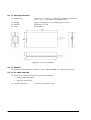
Overview of External Dimensions (TM-T88IV) . . . . . . . . . . . . . . . . . . . . . . . . . . . . . . . . . . . . . . . . . . . . . . . . . . . . . 5-6
External Dimensions. . . . . . . . . . . . . . . . . . . . . . . . . . . . . . . . . . . . . . . . . . . . . . . . . . . . . . . . . . . . . . . . . . . . . . . . 5-6
Operating Specifications (TM-T88IV). . . . . . . . . . . . . . . . . . . . . . . . . . . . . . . . . . . . . . . . . . . . . . . . . . . . . . . . . . . . . . 5-7
Appendix A Interfaces and Connectors
RS-232 Serial Interface . . . . . . . . . . . . . . . . . . . . . . . . . . . . . . . . . . . . . . . . . . . . . . . . . . . . . . . . . . . . . . . . . . . . . . . . . . A-1
Interface Board Specifications (RS-232-compliant) . . . . . . . . . . . . . . . . . . . . . . . . . . . . . . . . . . . . . . . . . . . . . . A-1
Functions of each Connector Pin . . . . . . . . . . . . . . . . . . . . . . . . . . . . . . . . . . . . . . . . . . . . . . . . . . . . . . . . . . . . . A-2
XON/XOFF . . . . . . . . . . . . . . . . . . . . . . . . . . . . . . . . . . . . . . . . . . . . . . . . . . . . . . . . . . . . . . . . . . . . . . . . . . . . . . . A-2
Code . . . . . . . . . . . . . . . . . . . . . . . . . . . . . . . . . . . . . . . . . . . . . . . . . . . . . . . . . . . . . . . . . . . . . . . . . . . . . . . . . . . . . A-3
IEEE 1284 Parallel Interface . . . . . . . . . . . . . . . . . . . . . . . . . . . . . . . . . . . . . . . . . . . . . . . . . . . . . . . . . . . . . . . . . . . . . . A-3
Modes . . . . . . . . . . . . . . . . . . . . . . . . . . . . . . . . . . . . . . . . . . . . . . . . . . . . . . . . . . . . . . . . . . . . . . . . . . . . . . . . . . . . A-3
Interface Signals. . . . . . . . . . . . . . . . . . . . . . . . . . . . . . . . . . . . . . . . . . . . . . . . . . . . . . . . . . . . . . . . . . . . . . . . . . . . A-5
viii Contents
Rev. A
TM-T88IV Technical Reference Guide
Appendix B Options and Consumables
Roll Paper. . . . . . . . . . . . . . . . . . . . . . . . . . . . . . . . . . . . . . . . . . . . . . . . . . . . . . . . . . . . . . . . . . . . . . . . . . . . . . . . . . . . . B-1
Power Supply . . . . . . . . . . . . . . . . . . . . . . . . . . . . . . . . . . . . . . . . . . . . . . . . . . . . . . . . . . . . . . . . . . . . . . . . . . . . . . . . . B-1
PS-180 . . . . . . . . . . . . . . . . . . . . . . . . . . . . . . . . . . . . . . . . . . . . . . . . . . . . . . . . . . . . . . . . . . . . . . . . . . . . . . . . . . . . B-1
Appendix C Character Code Tables
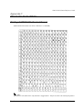
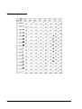
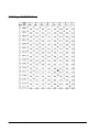
Page 0 (PC437: USA, Standard Europe) . . . . . . . . . . . . . . . . . . . . . . . . . . . . . . . . . . . . . . . . . . . . . . . . . . . . . . . . . . .
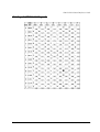
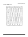
Page 1 (Katakana) . . . . . . . . . . . . . . . . . . . . . . . . . . . . . . . . . . . . . . . . . . . . . . . . . . . . . . . . . . . . . . . . . . . . . . . . . . . . . .
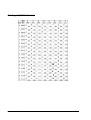
Page 2 (PC850: Multilingual) . . . . . . . . . . . . . . . . . . . . . . . . . . . . . . . . . . . . . . . . . . . . . . . . . . . . . . . . . . . . . . . . . . . .
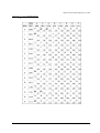
Page 3 (PC860: Portuguese). . . . . . . . . . . . . . . . . . . . . . . . . . . . . . . . . . . . . . . . . . . . . . . . . . . . . . . . . . . . . . . . . . . . . .
Page 4 (PC863: Canadian-French) . . . . . . . . . . . . . . . . . . . . . . . . . . . . . . . . . . . . . . . . . . . . . . . . . . . . . . . . . . . . . . . .
Page 5 (PC865: Nordic) . . . . . . . . . . . . . . . . . . . . . . . . . . . . . . . . . . . . . . . . . . . . . . . . . . . . . . . . . . . . . . . . . . . . . . . . .
Page 16 (WPC1252). . . . . . . . . . . . . . . . . . . . . . . . . . . . . . . . . . . . . . . . . . . . . . . . . . . . . . . . . . . . . . . . . . . . . . . . . . . . .
Page 17 (PC866: Cyrillic #2). . . . . . . . . . . . . . . . . . . . . . . . . . . . . . . . . . . . . . . . . . . . . . . . . . . . . . . . . . . . . . . . . . . . . .
Page 18 (PC852: Latin2) . . . . . . . . . . . . . . . . . . . . . . . . . . . . . . . . . . . . . . . . . . . . . . . . . . . . . . . . . . . . . . . . . . . . . . . . .
Page 19 (PC858: Euro) . . . . . . . . . . . . . . . . . . . . . . . . . . . . . . . . . . . . . . . . . . . . . . . . . . . . . . . . . . . . . . . . . . . . . . . . . .
Page 255 (Blank Page) . . . . . . . . . . . . . . . . . . . . . . . . . . . . . . . . . . . . . . . . . . . . . . . . . . . . . . . . . . . . . . . . . . . . . . . . . .
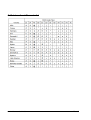
International Character Set . . . . . . . . . . . . . . . . . . . . . . . . . . . . . . . . . . . . . . . . . . . . . . . . . . . . . . . . . . . . . . . . . . . . . .
C-1
C-2
C-3
C-4
C-5
C-6
C-7
C-8
C-9
C-10
C-11
C-12
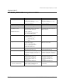
Appendix D TM-T88IV/TM-88III Comparison Table
Contents
ix
x Contents
Rev. A
TM-T88IV Technical Reference Guide
Chapter 1
Product Overview
The TM-T88IV thermal printer product is currently available from EPSON. In addition, the PS170, the power supply, is obsolete and no longer available. It is described only for legacy
support. The currently available power supply, the PS-180, works with TM-T88IV.
1.1 Features
The TM-T88IV printer has the following features:
❏ Printing
•
High-speed printing (200 mm/s {7.9"/s} maximum), which enables issuing of batch
receipts.
•
Graphics are also printed with a high-speed printing.
•
With a two-color print control, two-color printing is possible on the two-color thermal
paper.
❏ Printer handling
•
Easy drop-in paper loading.
❏ Software
•
Command protocol is based on the ESC/POS® Proprietary Command System.
•
OPOS ADK and Windows® printer drivers are available.
•
In addition to supporting several kinds of bar code printing, two-dimensional code
(PDF417, QR code) printing is possible.
•
Various layouts are possible by using page mode.
•
A maintenance counter function is supported.
❏ General
•
Rev. A
Various interface boards (EPSON UB series) can be used.
Product Overview 1-1
1.2 Product Structure
1.2.1 Model
❏ Product Name
TM-T88IV (current product)
•
Print method:
Thermal line printing
•
Interface specifications:
Serial interface specifications (RS-232C)
Parallel interface specifications (IEEE 1284-compliant)
USB interface specifications (Full speed)
Ethernet interface specifications (10/100Base-T)
Wireless LAN interface specifications (802.11b)
•
Paper width specifications:
80 mm {3.15"} width specifications
1.2.2 Accessories
❏ Printer (body)
❏ Roll paper × 1
❏ User’s manual × 1
❏ Power switch cover × 1
❏ Connector cover *
❏ External power supply unit model: PS-180 *
* May not be included with your printer.
1.2.3 Options
❏ External power supply unit
•
Model PS-180 (PS-180 supports the power-saving feature.)
❏ Affixing tapes (Model: DF-10)
❏ Hanging bracket set (Model: WH-10)
❏ Various interface board (UB series)
1.2.4 Consumable products
❏ Specified paper: Thermal paper
1-2 Product Overview
Rev. A
TM-T88IV Technical Reference Guide
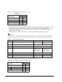
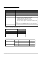
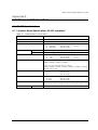
1.2.5 TM-T88IV Basic Specification Table
Table 1-1
TM-T88IV
1. High-speed print mode
Approx. 200 mm/s (7.9") maximum
2. High-speed power
consumption mode
Average : Approx. 1.8A
3. Serial interface selectable
baud rates
2400, 4800, 9600, 19200, 38400, 57600, 115200
Default Setting: 9600
Settable baud rate with DIP switches 1-7/1-8:
4800, 9600, 19200, 38400
Settable baud rate with commands:
2400, 4800, 9600, 19200, 38400, 57600,115200
4. Conditions for canceling
receive buffer BUSY state *
Set with DIP SW2-5 *
5. Supported character sets
(extended graphics)
11 pages including WPC 1252,
PC866 [Cyrillic #2], PC852 [Latin2])
6. Driver (EPSON OPOS ADK,
Advanced Printer Driver)
• Some baud rates cannot be used in serial
communications (38400 bps).
Note: The driver cannot set a 38400 bps baud
rate.
* For details on the conditions for canceling the receive buffer BUSY state, refer to “DIP Switch Functions” (page 2-3).
1.3 Part Names and Basic Operation
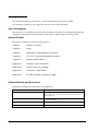
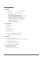
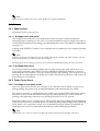
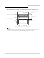
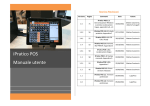
1.3.1 Part Names
Printer cover
Control panel
Cutter cover
Cover open button
Power switch
Figure 1-1 Printer part names
* For details on DIP switch settings, refer to “DIP Switch Positions and Steps for Changing DIP Switch
Settings” (page 2-2).
Rev. A
Product Overview 1-3
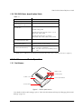
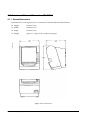
1.3.2 Control Panel
TM-T88IV
(POWER) LED
ERROR LED
PAPER OUT LED
FEED button
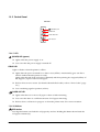
1.3.2.1 LED
(POWER) LED (green)
❏ Lights when the power supply is on.
❏ Goes out when the power supply is turned off.
ERROR LED
Lights or flashes when the printer is offline.
❏ Lights after the power is turned on or after a reset (offline). Automatically goes out after a
while to indicate that the printer is ready.
Lights when the end of the roll paper is detected, and when printing has stopped (offline). If
this happens, replace with new roll paper.
❏ Flashes when an error occurs. (For details about the flash codes, refer to “Error Codes” (page
3-8).)
❏ Goes out during regular operation (online).
PAPER OUT LED
❏ Lights when there is no more roll paper or there is little remaining.
❏ Goes out when there is a sufficient amount of roll paper remaining.
❏ Flashes when a self-test is in progress or when the printer waits for a macro execution.
1.3.2.2 Buttons
FEED button
Pressing this button once feeds the roll paper by one line. Holding this button down feeds the
roll paper continuously.
1-4 Product Overview
Rev. A
TM-T88IV Technical Reference Guide
1.3.3 Power Switch
The power switch is located at the bottom right front of the printer. (Refer to “Printer part
names” (page 1-3).)
Turn the printer on or off. The marks on the switch (0 = on / 1 = off) indicate the printer switch
position.
CAUTION:
Before turning on the printer be sure to check that the AC adapter is connected to the
power supply.
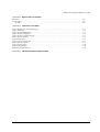
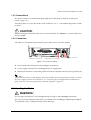
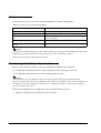
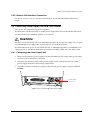
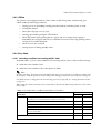
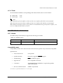
1.3.4 Connectors
All cables are connected to the connector panel on the lower rear of the printer.
FG
FG
Interface connector
DK
Drawer kick-out connector
DC24V
Power supply connector
Figure 1-2 Connector panel
❏ Drawer kick-out connector for connecting the cash drawer
❏ Power supply connector for connecting the power supply unit
❏ Interface connector to connect the printer to the host computer interface (serial, parallel, etc.)
Note:
The picture above shows a serial interface model. For details on the various interfaces and how to connect
the power supply connector and cash drawer, see “Connecting Power Supply Unit and Cash Drawer”
(page 2-15) and “Connecting the Printer to the Host Computer” (page 2-8).
1.4 Handling the Printer
WARNING:
Do not open the printer cover during printing. Doing so may damage the printer.
Do not touch the manual cutter with your hands when installing or replacing roll paper.
The manual cutter is sharp and may cause an injury.
Rev. A
Product Overview 1-5
1.4.1 Installing and Replacing Roll Paper
Note:
Be sure to use roll paper that meets printer specifications. See Appendix B for details on the paper
specifications.
Do not use roll paper whose trailing end is glued to the roll paper core.
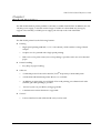
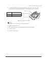
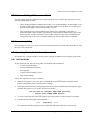
1.4.1.1 Installing Roll Paper
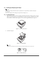
1. Make sure the host has not sent a printing command to the printer, and press the cover open
button to open the printer cover. If the printer cover does not open, a probable cause is that
the autocutter is locked. If this happens, refer to “Removing Jammed Paper” (page 1-7).
Figure 1-3 Cover open button
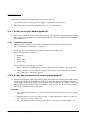
2. Load the roll paper.
Figure 1-4 Loading paper
Note:
When loading the roll paper, pay attention to the direction that the roll paper is fed out of the printer.
Figure 1-5 Paper direction
1-6 Product Overview
Rev. A
TM-T88IV Technical Reference Guide
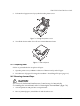
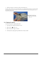
3. Pull out the roll paper toward you, then close the printer cover.
Figure 1-6 Closing the printer cover
4. Tear off the leading edge of the roll paper using the manual cutter.
Figure 1-7 Tear off paper
1.4.1.2 Replacing Paper
Follow the procedure below to replace roll paper.
1. Open the printer cover, and remove the core of the previously used roll paper.
2. Insert the new roll paper following the procedure in “Installing Roll Paper” (page 1-6).
1.4.2 Removing Jammed Paper
CAUTION:
Do not touch the thermal head because it can be very hot after printing.
For handling the thermal head, refer to “Cleaning the Thermal Head” (page 1-8).
1. Turn the printer off and press the cover open button.
2. Remove jammed paper, reinstall the roll, and close the cover.
Rev. A
Product Overview 1-7
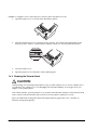
If paper is caught in the cutter and you cannot open the printer cover
1. Open the cutter cover as shown in the illustration below.
2. Turn the knob until you see a triangle in the opening. This returns the cutter blade to the
normal position. There is a label near the cutter to assist you. See the illustration below.
3. Close the cutter cover.
4. Open the printer cover and remove the jammed paper.
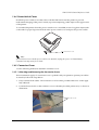
1.4.3 Cleaning the Thermal Head
CAUTION:
After printing, the thermal head can be very hot. Be careful not to touch it and to let it
cool before you clean it. Do not damage the thermal head by touching it with your
fingers or any hard object.
Turn off the printer, open the printer cover, and clean the thermal elements of the thermal head
with a cotton swab moistened with an alcohol solvent (ethanol, methanol, or IPA).
Epson recommends cleaning the thermal head periodically (generally every 3 months) to
maintain receipt print quality.
1-8 Product Overview
Rev. A
TM-T88IV Technical Reference Guide
1.4.4 Power Switch Cover
Install the power switch cover that comes with the TM-T88IV onto the printer to prevent
inadvertent changing of the power switch, to prevent tampering, and to improve the appearance
of the printer.
To reset the TM printer when the power switch cover is installed, insert a long, thin object (such
as the end of a paper clip) into the hole in the power switch cover and press the power switch.
Power Switch Cover
Note:
If an accident occurs with the power switch cover attached, unplug the power cord immediately.
Continued use may cause fire or shock.
1.4.5 Connector Cover
Use the following method to attach the connector cover.
1.4.5.1 Attaching and Removing the Connector Cover
These instructions apply if a connector cover is packed with your printer to protect your cables.
To attach it, follow the steps below:
1. First, connect all the cables. The connector cover has three possible cable exits: on the right,
left, and back.
2. Position the two hooks on the connector cover so that they hook the printer case, as shown in
illustration.
The two hooks
Rev. A
Product Overview 1-9
3. Push the connector cover down to click onto the printer case.
To remove the connector cover, turn the printer over, and push the connector cover down while
pushing both sides of the connector cover inward to detach the hooks from the printer case as
shown in the illustration.
pushing both sides of the
connector cover inward to
detach the hooks from the
printer case
1.4.6 Shipping Procedures
Do the following before shipping the printer.
1. Press the power switch to turn the power off.
2. Make sure the
LED is out.
3. Remove the power supply connector.
4. Pack the printer, keeping the top and bottom correctly oriented.
1-10 Product Overview
Rev. A
TM-T88IV Technical Reference Guide
Chapter 2
Setup
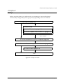
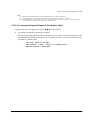
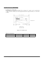
Before using the printer, you need to make various settings to increase the printer's
functionality. Configure the printer appropriately depending on the environment.
1. Install the printer (page 2-2)
Detailed setup
2. Set the DIP switches (page 2-2)
3. Set the roll paper near-end detector (page 2-6)
Note: Detailed setup sometimes
can be omitted.
4. Connect the printer to the host computer (page 2-8)
5. Connect the power supply and cash drawer (page 2-15)
6. Install the driver (page 2-16)
End
Figure 2-8 Setup flowchart
Rev. A
Setup 2-1
2.1 Installing the Printer
In addition to regular horizontal installation, the printer can be hung on a wall using the
optional WH-10 Wall Hanging Bracket Set.
2.1.1 Precautions for Horizontal Installation
❏ Install the printer in a flat, horizontal position.
❏ Avoid locations susceptible to dust and other foreign matter.
❏ Be sure to avoid bumping so that the printer is not exposed to strong impact during
operation.
❏ Avoid placing the printer on top of the power supply or other cables or other objects.
2.1.2 Precautions for Wall Installation
❏ Make the following settings on the printer when you hang it on a wall. For details, refer to
the installation manual provided with the optional WH-10 Wall Hanging Bracket Set.
•
Install the roll paper stopper
•
Adjust of near-end detector
•
Attach the connector cover
•
Install the WH-10 Wall Hanging Bracket Set
❏ For other details, refer to the installation manual provided with the optional WH-10 Wall
Hanging Bracket Set option.
CAUTION:
When hanging the printer on the wall with the hanging bracket set, be sure to attach a
connector cover to the printer.
2.2 Setting the DIP Switches
On this printer, you can make various settings with DIP switches.
Note:
Serial interface communication conditions must be set on serial interface model printers.
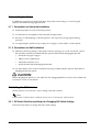
2.2.1 DIP Switch Positions and Steps for Changing DIP Switch Settings
Follow the steps below to change the DIP switch settings.
2-2 Setup
Rev. A
TM-T88IV Technical Reference Guide
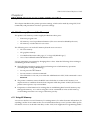
CAUTION:
Before you remove the DIP switch cover, turn the printer off. Otherwise, a short-circuit
may cause the printer to malfunction.
1. Make sure the power supply for the printer is turned off.
2. Unscrew the screw to remove the DIP switch cover from the base of the printer.
DSW1
DSW2
Figure 2-9 Removing the DIP switch cover
3. Set the DIP switches as desired, using the tip of a tool, such as a small screwdriver.
4. Attach the DIP switch cover, and screw in place.
Note:
New DIP switch settings are enabled after the printer is turned on.
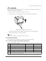
2.2.2 DIP Switch Functions
The DIP switch functions depend on your printer’s interface specifications.
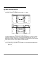
2.2.2.1 DIP switch settings for serial interface specifications
Table 2-2 Switch bank 1 settings
SW
Function
ON
OFF
1-1
Data receive error
Ignore
“?” is printed *
1-2
Receive buffer size
45 bytes
4KB *
1-3
Handshake
XON/XOFF
DTR/DSR *
1-4
Bit length
7 bits
8 bits *
1-5
Parity check
Yes
No *
1-6
Parity selection
Even
Odd *
1-7,
1-8
Baud rate selection
(See the “Baud rate selection” tables below.)
For details on DIP SW1-2: Receive buffer size, also refer to DIP SW2-5: Cancellation of receive buffer full BUSY state.
Rev. A
Setup 2-3
Table 2-3 Baud rate selection (DIP SW1-7, 1-8)
TM-T88IV
Switch no.
Baud rate (BPS)
1-7
1-8
38400 (Default)**
ON
ON
4800
OFF
ON
9600*
ON
OFF
19200
OFF
OFF
* Factory setting.
** The baud rate can be changed with the setting values for the communication conditions of the
serial interface. The serial interface communication conditions can be changed using
command and Memory switch setting utility. The setting values are 2400, 4800, 9600, 19200,
38400, 57600, and 115200.
For the memory switch setup utility, see “Memory Switch Setting Utility” (page 3-6).
Note:
The values of the communication conditions of the serial interface set with commands are enabled only
when DIP switches 1-7 and 1-8 are On. Otherwise, the value selected with DIP switch 1 has priority.
Table 2-4 Switch bank 2 settings
SW
Function
ON
OFF
2-1
Handshake (BUSY) conditions
Receive buffer full
Printer offline or
receive buffer full *
2-2
Reserved (do not change setting)
Fixed to OFF
2-3, 2-4
Print density selection/low-power mode
(See separate table.)
2-5
Conditions for canceling receive buffer BUSY state
Releases BUSY when
remaining receive
buffer capacity
reaches 138 bytes.
2-6
Reserved (do not change setting)
Fixed to OFF
2-7
Pin # 6 reset signal
Used
Not used *
2-8
Pin # 25 reset signal
Used
Not used *
Releases BUSY when
remaining receive
buffer capacity
reaches 256 bytes.
For details on DIP SW2-1: BUSY conditions, also refer to “Busy State” (page 3-11).
Table 2-5 Print density selection (DIP SW2-3, 2-4)
Switch No.
Print density
Print density
Print density
2-4 Setup
2-3
2-4
ON
ON
Normal*
OFF
OFF
Medium
ON
OFF
Dark
OFF
ON
Low-power mode
Rev. A
TM-T88IV Technical Reference Guide
2.2.2.2 DIP switch settings for other interface specifications
The following DIP switch functions are for parallel interface/USB/Ethernet model printers.
Note:
* Factory setting
Table 2-6 Parallel/USB/Ethernet DIP switch bank 1
SW
Function
ON
OFF
1-1
Automatic line feed
Enabled at all times
Disabled at all times *
1-2
Receive buffer size
45 bytes
4KB *
1-3
Select paper sensors to output paper-end signals.
(Command default setting value.)
Disabled
Roll Paper end sensor
enabled, Roll Paper
nearend sensor
enabled
1-4
Error signal output
Disabled
Enabled
1-5 ~
1-8
Not defined
(Always use printer with these switches set to OFF.)
—
—*
Table 2-7 Parallel/USB/Ethernet DIP switch bank 2
SW
Function
ON
2-1
Handshake (BUSY conditions)
•
Receive buffer full
OFF
•
•
2-2
Reserved (do not change setting)
Fixed to OFF
2-3, 2-4
Print density selection/low-power mode
(See separate table.)
2-5
Conditions for canceling receive buffer BUSY state
Releases BUSY when
remaining receive
buffer capacity
reaches 138 bytes.
2-6, 2-7
Reserved (do not change setting)
Fixed to OFF
2-8
Pin #31reset signal (do not change setting)
Fixed to ON
Offline *
Receive buffer full
Releases BUSY when
remaining receive
buffer capacity reaches
256 bytes.
DIP SW2-1: For details on the BUSY condition, also refer to “Busy State” (page 3-11).
Table 2-8 Selection of print density
Switch no.
Print density
Print density
Print density
Rev. A
2-3
2-4
Low-power mode
ON
ON
Normal*
OFF
OFF
Medium
ON
OFF
Dark
OFF
ON
Setup 2-5
2.3 Customized value
The customized value is set with command and Memory switch setting utility.
Table 2-9 Types of the Customized Value
Function
Value
Selection of print density
70% – 130% (13 levels in 5% each)
Selection of print speed
Level 1–9 (9 levels)
Number of head energizing
One-part energizing, Two-part energizing, Four-part energizing,
or Auto energizing
Selection of print control
Single-color control / Two-color control
Selection of black-color density in two-color
printing
Light / Medium / Dark
Note:
Print speed is controlled depending on the number of the head energizing. The maximum print speed (200
mm/s) can be performed only when one-part energizing or auto-energizing is selected.
In the power saving mode, all settings are ignored.
2.4 Adjusting the Roll Paper Near-End Detector
Below are two situations where a roll paper NE detector adjustment is required.
❏ To adjust the detection position to suit the diameter of the roll paper core used.
❏ To adjust the detection position of remaining amount of paper.
Note:
Since roll paper cores vary slightly in shape, depending on paper roll design and manufacturing
tolerances, it impossible to detect the remaining paper exactly. Use roll paper with a core inner diameter of
12 mm {0.47"} and outer diameter of 18 mm {0.71"} so that the NE detector can detect the remaining
paper as accurately as possible.
Follow the procedure below to adjust the roll paper NE detector position.
1. Open the roll paper cover, and remove the roll paper.
2-6 Setup
Rev. A
TM-T88IV Technical Reference Guide
2. Loosen the adjustment screw fastening the detector, and align the upper edge of the
positioning plate with the adjustment position. Adjustment positions are as follows:
Adjustment screw
Adjustment
position
Remaining amount of roll
paper (outer diameter: mm)
Upper
Approx. 27
Lower
Approx. 23
Positioning plate
Detection lever
Figure 2-10 NE detector positions
Note:
The adjustment screw is set to the lower position before shipment.
3. Tighten the adjustment screw.
4. After adjustment, make sure that the detection lever operates smoothly.
5. Load the roll paper.
6. Close the roll paper cover.
Rev. A
Setup 2-7
2.5 Connecting the Printer to the Host Computer
2.5.1 Serial Interface Connection
2.5.1.1 Cross cable wiring diagrams
The wiring selections for available serial cross cables are as follows:
Figure 2-11 Cross cable diagrams
The cable needed depends on printer control and handshake method. You can operate the TM
printer with a Windows driver, OPOS, or ESC/POS commands. XON/XOFF, DTR/DSR, or
RTS/CTS are available as handshake controls. For details on available cables for each connection
form, refer to “Section 2.5.1.2, Serial interface connection diagrams.”
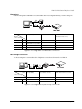
2.5.1.2 Serial interface connection diagrams
When the TM printer is connected to a host computer by the serial interface, the following two
connection forms are possible:
•
Stand alone
•
Pass-through connection
2-8 Setup
Rev. A
TM-T88IV Technical Reference Guide
Stand alone
Both the TM printer and DM-D are connected to the host computer directly via the serial port.
Application
control
XON/XOFF
(except OPOS)
DTR/DSR
(DOS, OPOS, Visual C)
RTS/CTS
(DOS, Windows driver, Visual C,
Visual Basic MSComm)
1
Type A or B
—
—
2
DM-D500: A, B
Other DM-D: not possible
—
—
1
—
Type A or B
Type B
2
—
Type A or B
Type B
TM side
control setting
XON/XOFF
DTR/DSR
Figure 2-12 Configuration of stand-alone connection
Pass-through connection
The host computer is connected to the TM printer over the serial interface via DM-D.
XON/XOFF
(except OPOS)
DTR/DSR
(DOS, OPOS, Visual C)
RTS/CTS
(DOS, Windows driver, Visual C,
Visual Basic MSComm)
Not possible
—
—
1
—
Type A or B
Type B
2
—
Type A or B
Type A or B
Application
control
TM side
control setting
XON/XOFF
DTR/DSR
Figure 2-13 Configuration of pass-though connection
Rev. A
Setup 2-9
2.5.1.3 Connecting the serial interface (RS-232) cable
WARNING:
Be sure to turn off the power supply for both the printer and host computer before
connecting the cables.
1. Insert the interface cable connector firmly into the interface connector on the connector
panel.
2. When using connectors equipped with screws, tighten them to secure the connectors firmly.
3. When using interface cables equipped with a ground line, attach the ground line to the
screw hole marked “FG” on the printer.
4. Connect the other end of the interface cable to the host computer.
FG
FG
Interface connector
DK
Drawer kick-out connector
DC24V
Power supply connector
Figure 2-14 Printer connectors
2.5.2 Parallel Interface Connection
The parallel interface model TM printer is connected to the host computer via the parallel port.
When a customer display (DM-D) is to be connected, connect the TM printer to the host
computer via the serial port.
2-10 Setup
Rev. A
TM-T88IV Technical Reference Guide
2.5.2.1 Parallel interface connection diagram
Figure 2-15 Parallel interface connection
2.5.2.2 Connecting the parallel interface cable
1. Insert the interface cable connector firmly into the interface connector on the connector
panel.
2. Press down the clips on either side of the connector to lock it in place.
3. When using interface cables equipped with a ground line, attach the ground line to the
screw hole marked “FG” on the printer.
4. Connect the other end of the interface cable to the host computer.
2.5.3 USB Interface Connection
Connect the TM printer to the host computer with a USB cable. A second TM printer can be
connected via a self-powered USB hub from a printer connected to the host computer.
Note:
A customer display (DM-D) can be connected to a USB model TM-T88IV (with UB-U01/UB-U02) by
the exclusive modular cable (RJ-45). When connecting the customer display, connect the modular jack
from the customer display to the DM connector (refer to “Installing the locking wire saddle” (page 2-12)).
When connecting the customer display to a USB model TM-T88IV (with UB-U01/UB-U02), set the
communication conditions of the customer display as follows:
Rev. A
•
Baud rate:19200 bps
•
Bit length:8-bit
•
Parity:no parity
•
Stop bit:1
Setup 2-11
2.5.3.1 USB Interface Connection Diagram
Example:
Figure 2-16 USB connection
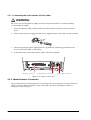
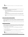
2.5.3.2 Connecting the USB interface cable
1. Attach the locking wire saddle at the location shown in the figure below.
2. Put the USB cable through the locking wire saddle as shown in the figure below.
Note:
Putting the USB cable through the locking wire saddle, as shown in the figure below, prevents the
cable from coming unplugged.
USB upstream connector
UB-board
Locking wire saddle
USB cable
DM connector
Figure 2-17 Installing the locking wire saddle
3. Connect the USB cable from the host computer to the USB upstream connector.
4. Up to 2 USB devices can be connected to a USB model TM-T88IV by using 2 USB
downstream connectors.
Note:
The hub installed in a USB model connector panel is a bus-power-supply hub. It is important to note
that bus-power-supply hubs (including other USB model TM printers) and bus-power-supply
functions with a current consumption of 100 mA or more cannot be connected directly to the printer.
2-12 Setup
Rev. A
TM-T88IV Technical Reference Guide
To use USB model TM printers, the TM printer driver (EPSON OPOS ADK or advanced printer
driver) must be installed on the host computer. Get the latest driver information from one of the
following URLs:
For customers from North America, go to the following web site:
http://pos.epson.com/
For customers from other countries, go to the following web site:
http://www.epson-pos.com/
Select the product name from the “Select any product” pull-down menu.
For details on EPSON OPOS ADK or advanced printer driver, refer to “Introducing the Control
Methods” (page 3-1).
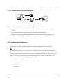
2.5.4 Ethernet Interface Connection
Connect a TM printer with an Ethernet interface to a network by an Ethernet cable via a hub.
2.5.4.1 Ethernet Interface Connection Diagram
Example:
Figure 2-18 Ethernet connection
Note:
When a TM printer is connected to the host computer via a network interface, a customer display (DM-D)
cannot be connected to the TM printer. If a customer display must be connected, connect it to the host
computer’s serial interface.
Rev. A
Setup 2-13
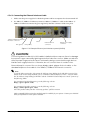
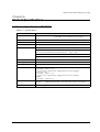
2.5.4.2 Connecting the Ethernet Interface Cable
1. Make sure the power supplies for both the printer and host computer have been turned off.
2. For 10Base-T/100Base-T Ethernet, connect a 10Base-T/100Base-T cable to the 10Base-T/
100Base-T Ethernet connector by pressing firmly until the connector clicks into place.
10Base-T/100Base-T Ethernet
interface connector
LED (green)
Switch
LED (yellow)
Drawer kick-out
connector
Printer power supply
connector
Figure 2-19 Example Ethernet port interface panel (UB-E02)
CAUTION:
Connecting devices directly to LAN cables installed outdoors exposes them to damage
from power surges caused by lightning and other inductive sources. Make sure devices
without proper surge protection are cushioned by being connected through devices
that do have surge protection. Otherwise, do not connect them to outdoor lines.
Never attempt to connect the customer display cable, drawer kick-out cable, or the
standard telephone line cable to the 10Base-T/100Base-TX Ethernet connector.
Note:
To use the Ethernet interface, the separate IP Address Setup Utility for the UB-E02 is required. For
details on the various setup methods, refer to “UB-E02 Technical Reference Guide.” You can obtain
the “IP Address Setup Utility for UB-E02” and the “UB-E02 Technical Reference Guide” from one of
the following URLs:
For customers from North America, go to the following web site:
http://pos.epson.com/
For customers from other countries, go to the following web site:
http://www.epson-pos.com/
Select the product name from the “Select any product” pull-down menu.
Other compatible Ethernet interface modules may be available for your printer. Contact your EPSON
dealer for information on the options available.
2-14 Setup
Rev. A
TM-T88IV Technical Reference Guide
2.5.5 Wireless LAN Interface Connection
For details on how to set up a wireless LAN interface, see the UB-R02 Technical Reference
Guide.
2.6 Connecting Power Supply Unit and Cash Drawer
Always use one of the following power supplies:
The EPSON PS-180 (the currently available power supply that can be used with the TM-T88IV).
Use the cash drawer handled by EPSON or your dealer.
WARNING:
Always use the EPSON PS-180 or an equivalent product as the power supply unit. Using a
nonstandard power supply can result in electric shock and even fire.
Should a fault ever occur in the EPSON PS-180, or equivalent product, immediately turn
off the power to the printer and remove the power supply cable from the wall socket.
2.6.1 Connecting the Power Supply Unit
1. Make sure the printer’s power supply is turned off and the power supply unit’s power cable
has been removed from the wall socket.
2. Check the specifications label on the power supply unit to confirm that the wall socket
power supply meets the rated voltage requirements.
3. Insert the connector of the power supply cable onto the power supply connector (labeled
DC24V).
FG
FG
DK
DC24V
Power supply
connector
Figure 2-20 Connecting the power supply
Rev. A
Setup 2-15
CAUTION:
Be sure to remove the power supply unit’s cable from the wall socket whenever
connecting or disconnecting the power supply unit to the printer. Failure to do so may
result in damage to the power supply unit or the printer.
Make sure the wall socket power supply satisfies the rated voltage requirements of the
power supply unit. Never insert the power supply cable plug into a socket that does not
meet the rated voltage requirements of the power supply unit. Doing so may result in
damage to both the power supply unit and the printer.
Note:
Before removing the DC cable connector from the EPSON PS-180 (current model power supply), make
sure the power supply cable has been removed from the power supply unit, then grasp the arrow-marked
section of the connector and pull straight out.
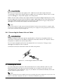
2.6.2 Connecting the Drawer Kick-out Cable
WARNING:
Prepare a drawer that meets printer specifications. Otherwise, the drawer kick-out
solenoid or other parts in the drawer might burn and cause a fire. This may also cause
the printer to malfunction at the same time.
Do not insert a telephone line into the drawer kick-out connector. Doing so may
damage the telephone line or printer.
Connect the connector of the drawer kick-out cable to the printer.
Figure 2-21 Connecting the drawer-kick cable
2.7 Installing the Driver
To use the TM printer, either the Advanced Printer Driver (APD) (Windows driver) or the
EPSON OPOS ADK (OCX driver) must be installed. For an outline of each driver, refer to
“Introducing the Control Methods” (page 3-1). For details on installation methods, refer to the
manual for the respective driver.
Note:
ESC/POS commands are also available for directly controlling the printer without the user of a driver. For
details on ESC/POS commands, also refer to “ESC/POS Commands” (page 3-6).
2-16 Setup
Rev. A
TM-T88IV Technical Reference Guide
Chapter 3
Application Development Information
This chapter describes how to control the printer and gives information useful for printer
application development.
3.1 Introducing the Control Methods
The TM printer can be controlled and can print using any of the following 3 methods.
1. Windows printer driver (EPSON Advanced Printer Driver or APD)
2. EPSON OPOS ADK
3. ESC/POS commands
Depending on the driver and interface used, the IP setup tool for the Ethernet model, USB
device driver, logo printing registration utility (TMFlash logo utility), etc. are available. Get the
latest information from one of the following URLs:
For customers from North America, go to the following web site:
http://pos.epson.com/
For customers from other countries, go to the following web site:
http://www.epson-pos.com/
Select the product name from the “Select any product” pull-down menu.
3.1.1 Windows Driver (EPSON Advanced Printer Driver)
The EPSON Advanced Printer Driver provides the TM printer with satisfactory control as a
Windows driver.
3.1.1.1 EPSON Advanced Printer Driver overview
EPSON Advanced Printer Driver has the following features:
❏ Supplies a Windows printer driver for the TM printer to enable printing from a general
Windows application.
❏ Can execute POS printer-specific functions, such as cutting paper and opening a drawer.
❏ Can print printer-resident fonts by selecting the font type.
❏ Can get the printer status using programming languages, such as Visual Basic (VB), via
status API. This uses the printer’s bidirectional communication capability in the Windows
standard printer driver operating environment.
Note:
The status API is a printer control API originally supplied by EPSON. This can be used to get the printer
status and send ESC/POS commands.
Rev. A
Application Development Information 3-1
3.1.1.2 EPSON Advanced Printer Driver contents
The installer automatically evaluates the target PC environment and automatically installs the
DLL and software components necessary for operation. You can select the drivers, sample
programs, and manuals to be installed.
❏ Drivers
You can select the driver, based on its purpose (drivers also can be installed simultaneously),
including two-color printing, smoothing, continuous printing, cutting method options, and
other functions.
•
Receipt: For receipt printing
❏ Sample programs
You can install sample programs in Visual Basic and Visual C++ to use status API.
❏ Manuals
The following manuals can be installed:
•
User's manual (for developers)
•
Engineering data for each status
•
Main function control methods (for WordPad and VB)
3.1.1.3 EPSON Advanced Printer Driver support environment
❏ Supported interfaces
•
Serial, parallel, USB, Ethernet
❏ Supported operating systems (with confirmation of system operation)
•
Microsoft Windows NT4.0 SP6a English
•
Microsoft Windows 2000 SP4 English
•
Microsoft Windows XP SP2 English
•
Microsoft Windows XP Embedded
Refer to the release note for the driver for the latest information.
❏ Supported development languages
•
Visual Basic
•
Visual C++
3-2 Application Development Information
Rev. A
TM-T88IV Technical Reference Guide
❏ Supported devices
Refer to the release note for the driver for details on available equipment.
•
EPSON receipt printer
•
EPSON customer display
•
EPSON cash drawer
Note:
A separate USB device driver is required for a USB model printer, and a separate IP setup utility is
required for an Ethernet model printer. See the manual packed with the APD.
When you use the APD for the TM-T88IV, using TrueType fonts may slow printing down, due to the
speed of communication between the printer and host computer. If this happens, we recommend using
printer-resident fonts. For details on how to use resident fonts, see the user's manual for the APD.
Printing with TrueType fonts on other interfaces may have a slight influence on customer applications. In
that case, use the printer-resident fonts. Because of the restrictions of some customer applications, when
the APD is used with that application, resident fonts sometimes cannot be used, even if they are specified.
When OPOS is used, this problem does not arise because only the printer-resident fonts are available.
3.1.1.4 Driver information and download destination
Get the latest driver information from one of the following URLs:
For customers from North America, go to the following web site:
http://pos.epson.com/
For customers from other countries, go to the following web site:
http://www.epson-pos.com/
Select the product name from the “Select any product” pull-down menu.
3.1.2 EPSON OPOS ADK
The EPSON OPOS ADK supports the development environment required for OPOS application
development using OPOS Control as described by the OLE for Retail POS (simply called
“OPOS” from here on) Technology Association to supply the OPOS-compliant printer driver
(OCX). Use this control method to develop OPOS-compliant applications. EPSON’s OPOS ADK
has the following features:
❏ The EPSON OPOS ADK comprehensively supports the development environment required
for OPOS application development at customer sites, including not only OPOS Control
(CO + SO) proposed by the OPOS Association, but also the contents necessary for
development, ranging from the installers and setup utilities to sample programs and
manuals, and the function for getting logs for debugging, and silent installation that
achieves ease of installation on a target PC.
Rev. A
Application Development Information 3-3
❏ The EPSON OPOS ADK reduces the man-hours for application development, since it
handles the following functions that application developers up till now have had to
consider. The functions are supported by EPSON-original Direct IO with parameters,
power-on notification, offline buffer clear processing, and so on.
Note:
For details on the API functions, refer to the “Application Programmers Guide Specification” provided by
the OLE POS Technology Association.
3.1.2.1 EPSON OPOS ADK (OPOS Control) overview
OPOS Control included with the EPSON OPOS ADK has the following features:
❏ Supplies the CO for each device class and SO for EPSON devices.
❏ Direct IO with parameters available:
•
Gets the printer maintenance counter value
•
Prints NVRAM-stored bit images, etc.
❏ Power-on notification function (at power on, this function automatically restores the printer
to the state that was active before power off).
❏ Offline buffer clear processing (clears the print buffer contents in offline mode).
❏ Debugging function (trace function):
•
Obtains a log between the application and CO (target: used API and its return value)
•
Device status acquisition log (gets the offline and error causes that actually occurred in
the devices)
3.1.2.2 EPSON OPOS ADK contents
The installer of the EPSON OPOS ADK, Ver. 2.10 or later, has a silent installation function,
which can install the OPOS environment without a user interface and facilitate installation. With
the installer, the following OPOS-compliant OPOS Control for EPSON devices, manuals,
various utilities, and sample programs can be installed.
❏ OPOS Control for EPSON devices
Header files for CO, SO, C++, header files for VB, TLB file of CO, device information files, etc.,
can be installed.
❏ Manuals
•
User's guide (environment construction manual: installation/uninstallation, usage
methods for various utilities)
•
Application Development Guide (manual for OPOS-compliant application developer:
common manual, manual for each device)
3-4 Application Development Information
Rev. A
TM-T88IV Technical Reference Guide
❏ Various utilities
•
SetUpPOS utility
Facilitates selection of equipment and connection ports and various settings
(print wait time, etc.).
•
TM Flash logo utility
Saves a bitmap file to the printer or customer display, for example.
•
USB device driver
This driver is necessary to connect a USB model printer.
•
Sample programs
Sample programs for VB, VC++ can be installed.
3.1.2.3 EPSON OPOS ADK support environment
❏ Supported interfaces
•
Serial, parallel, USB, Ethernet
❏ Supported OSes (with confirmation of system operation)
•
Windows 95 Standard, OSR 2.5
•
Windows 98 Second Edition
•
Windows NT Ver. 4.0 SP5, SP6
•
Windows 2000 Professional
•
Windows XP Professional
Refer to the release note of the driver for the latest information.
❏ Supported development languages
•
Visual Basic
•
Visual C++
3.1.2.4 Driver information and download destination
Get the latest driver information from one of the following URLs:
For customers from North America, go to the following web site:
http://pos.epson.com/
For customers from other countries, go to the following web site:
http://www.epson-pos.com/
Select the product name from the “Select any product” pull-down menu.
Rev. A
Application Development Information 3-5
3.1.3 ESC/POS Commands
To directly control the TM printer using ESC/POS commands, EPSON proposes printing/
control via ESC/POS commands. The printer can be controlled directly by sending ESC/POS
commands from an application to the printer. For detailed information about ESC/POS
commands, please contact EPSON or your dealer.
3.1.4 Various Utilities
We provide the utilities described below for developers of TM printer applications. You can
obtain the utilities from one of the following URLs:
For customers from North America, go to the following web site:
http://pos.epson.com/
For customers from other countries, go to the following web site:
http://www.epson-pos.com/
Select the product name from the “Select any product” pull-down menu.
3.1.4.1 Memory Switch Setting Utility
This utility is designed to perform the memory switch-related functions of the TM printer easily.
❏ You can execute a communication test and self-test.
❏ You can set the switches, etc. (such as customized values and serial communication
condition).
3.1.4.2 IP address setup utility for UB-E02
This utility and its detailed manual for developers allow you to set an IP address for a 10Base-T/
100Base-TX Ethernet interface installed in the TM printer. Customers who have purchased the
Ethernet model TM printer need this utility.
3.1.4.3 Electronic logo storage utility for NVRAM
This utility is designed to save logos (bitmaps) to NVRAM (non-volatile RAM). By storing shop
logos to NVRAM, the print speed can be increased.
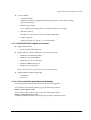
3.2 Switches and Buttons
On this printer, you can disable or enable the FEED button. For details on how to switch between
disabled or enabled, refer to the documentation for OPOS Advanced Printer Driver and ESC/
POS commands, respectively.
3-6 Application Development Information
Rev. A
TM-T88IV Technical Reference Guide
3.2.1 FEED Button
The printer feeds paper based on the line spacing set by the control method (OPOS, Advanced
Printer Driver, ESC/POS commands). However, you cannot feed paper using the FEED button
under the following conditions:
•
When the roll paper cover is open.
•
When performing a self-test (Press the FEED button to stop the self-test and press it again
to resume it).
•
When the FEED button has a function defined in a macro definition command (when
ESC/POS commands are used).
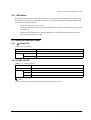
3.3 Panel LEDs and Error Status
3.3.1
(POWER) LED
Table 3-10 Power LED
Item
Specifications
LED color
Green
LED states
Off
Power is not supplied.
On
Power is supplied.
3.3.2 PAPER OUT LED
Table 3-11 PAPER OUT)LED
Item
Specifications
LED color
Red
LED states
Off
Roll paper is loaded.
On
A roll paper near end or paper end is detected.
Flashing
Self-test standby state or standby state when a macro execution command is used.
Note:
The macro function is available only when ESC/POS commands are used.
Rev. A
Application Development Information 3-7
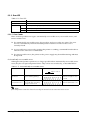
3.3.3 Error LED
Table 3-12 Error LED
Item
Specifications
LED color
Red
On states
Off
Printer is performing regular operations or is online.
On
Offline (excluding self-test with the FEED button).
Flashing
Error state.
3.3.3.1 Error Codes
There are three possible error types: automatically recoverable errors, recoverable errors, and
unrecoverable errors.
❏ For automatically recoverable errors, the user does not have to take any action. The error
recovers automatically when the head temperature returns to normal or the cover is
correctly closed.
❏ A recoverable error recovers by resetting the printer or sending a command from the driver
after the cause of the error is eliminated.
❏ For unrecoverable errors, the printer or the power supply may be malfunctioning and must
be repaired.
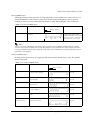
Automatically recoverable errors
Although normal printer operation is no longer possible when automatically recoverable errors
occur, they do not represent printer failure. They can be recovered easily, as described below.
Table 3-13 Automatically recoverable errors
Error
Error description
Error LED flash code
Recovery measure
Approx. 160 ms
Roll paper cover
open error
The roll paper cover was
opened during printing.
Recovers automatically
when the roll paper cover
is closed.
Print head
temperature error
A high temperature outside
the head drive operating
range was detected.
Recovers automatically
when the print head cools.
Note:
If the temperature cannot be detected correctly, an internal circuit connection error occurs.
3-8 Application Development Information
Rev. A
TM-T88IV Technical Reference Guide
Recoverable errors
Although normal printer operation is not possible after a recoverable error occurs, this is not a
printer malfunction. These errors can be recovered easily by turning the power on again or
sending an error recovery command from the driver after eliminating the cause of the error.
Table 3-14 Recoverable errors
Error
Error description
Error LED flash code
Recovery measure
Approx. 160 ms
Autocutter error
Autocutter does not work
correctly.
Remove the jammed paper or
foreign matter in the printer,
close the roll paper cover, send
the error recover command, or
turn the power on to recover.
Note:
The error recovery command is valid only if a recoverable error (excluding automatically recoverable
errors) occurs. If a recoverable error occurs, the printer recovers from the error upon receipt of an error
recovery command from the driver after the cause of the error is eliminated. Turning the printer’s power
off and on is not required.
Unrecoverable errors
Normal printer operation is no longer possible when unrecoverable errors occur. The printer
must be repaired.
Table 3-15 Unrecoverable errors
Error
Error description
Error LED flash code
Recovery measure
Approx. 160 ms
Memory R/W error
After R/W checking, the printer
does not work correctly.
Impossible to
recover
High voltage error
The power supply voltage is
extremely high.
Impossible to
recover
Low voltage error
The power supply voltage is
extremely low.
Impossible to
recover
CPU execution error
The CPU is executing an
incorrect address.
Impossible to
recover
UIB Error
An abnormal operation occurs
in UIB.
Impossible to
recover
Internal circuit
connection error
Internal circuits are not
connected correctly.
Impossible to
recover
Rev. A
Application Development Information 3-9
Note:
When an unrecoverable error occurs, turn off the power supply immediately.
3.4 Sensors
3.4.1 Paper Sensors
The printer has two paper sensors.
3.4.1.1 Roll paper near-end sensor
The roll paper near-end sensor uses the diameter of the roll paper to detect whether the
remaining paper is getting low. This sensor is located inside the roll paper supply unit, and you
can fine-tune the amount of remaining paper detected by this sensor. (For details on adjustment,
see page 2-6.)
Lighting of the PAPER OUT LED in a near-end state does not indicate an error. Regular printing
is possible.
Note:
Detection of the near-end status does not necessarily indicate the complete end of the roll paper. Use the
sensor as an indication of when to replace the roll paper.
By changing the driver setting, a print job can be canceled automatically during the near-end status.
3.4.1.2 Roll Paper End Sensor
The roll paper end sensor detects whether there is paper in the paper path. When there is no
paper (paper end status), the PAPER OUT LED and ERROR LED light to indicate an error has
occurred. If the sensor detects a roll paper end, the printer stops printing, even in the process of
printing. We recommend that you mainly rely on the roll paper near-end sensor and use the roll
paper end sensor secondarily.
3.4.2 Printer Cover Sensor
3.4.2.1 Roll Paper Cover Open Sensor
The cover-open sensor monitors the roll paper cover. When the sensor detects an open cover
during printing, the printer stops printing immediately and automatically goes offline.
This status is treated as an automatically recoverable error, and the ERROR LED flashes. When
the printer cover is closed, the ERROR LED goes out, and the printer goes online and starts
printing at the beginning of the line it was printing when the cover was opened.
When the printer recovers, it feeds paper to take up slack and starts printing from the beginning
of the line where the error occurred. In this case, double printing and printing position shift may
occur. When a cover open error occurs, we recommend clearing the printer’s print buffer by
sending the error recovery command from the driver, and resending the print data.
Note:
Whether the cover is open or not does not affect the status reported by the roll paper end sensor.
3-10 Application Development Information
Rev. A
TM-T88IV Technical Reference Guide
3.4.3 Offline
This printer is not equipped with an online/offline switch. The printer automatically goes
offline under the following conditions:
•
During power on (including resetting with the interface) until the printer is ready
•
During the self-test
•
When the roll paper cover is open
•
During paper feeding using the FEED button
•
When the printer stops printing due to a paper-end (if an empty paper supply is
detected by the roll paper end sensor or if the driver has been set to stop printing when a
roll paper near-end is detected)
•
When an error has occurred
•
During macro executing standby status
3.4.4 Busy State
3.4.4.1 Selecting conditions for invoking a BUSY state
With DIP SW2-1, you can select conditions for invoking a BUSY state as either of the following:
❏ When the receive buffer is full
❏ When the receive buffer is full or the printer is offline
Note:
In either case above, the printer enters the BUSY state after power is turned on (including resetting with
the interface), while the printer is in the standby state waiting for data, and when a self-test is being run.
For details on how to change the DIP switch setting for receive buffer full, see “Setting the DIP Switches”
on page 2-2.
When using the Advanced Printer Driver, DIP SW2-1 must be ON. When using OPOS, it can be either
ON or OFF.
Table 3-16 Printer BUSY conditions and status of DIP SW2-1
DIP SW2-1 status
Printer status
Offline
ON
OFF
During the period after power is turned on (including resetting with
the interface) to when the printer is ready to receive data.
BUSY
BUSY
During the self-test.
BUSY
BUSY
When the cover is open.
—
BUSY
During paper feed with the FEED button.
—
BUSY
When the printer stops printing due to a paper-end (when printer has
run out of roll paper).
—
BUSY
When an error has occurred.
—
BUSY
BUSY
BUSY
When the receive buffer is full
Rev. A
Application Development Information 3-11
Note:
When DIP SW2-1 is ON, the printer will not become BUSY even if printer hardware stops operating.
•
When an error has occurred
•
When the cover is open
•
When printing has stopped for a paper out
•
When paper is fed by the FEED button
3.5 NVRAM (Non-volatile Memory)
NVRAM is mounted on this printer, and bitmap images (for example, business logos) or other
data are written to it. Pay attention to the following when using NVRAM.
❏ The following restriction applies when performing operations (including storing and
deleting data) in NVRAM.
•
Do not use the FEED button.
❏ The printer sometimes enters the BUSY state when data is being written to NVRAM. It is
important not to send data from the host computer while the printer is in the BUSY state,
because the printer cannot process any received data.
❏ Frequent use of the functions for writing data to and deleting data from NVRAM may
damage the memory. As a rule, in using the various commands to write to NVRAM, avoid
writing more than an average of ten times per day.
3.6 Bar Code Printing
This printer can print the following types of bar codes:
UPC-A, UPC-E
JAN 8 (EAN 8), JAN 13 (EAN 13)
CODE 39
ITF (Interleaved 2 of 5)
CODABAR (NW-7)
CODE 93
CODE 128
PDF417 (2D code )
QR Code
To set and print each bar code, refer to the OPOS, Advanced Printer Driver, and ESC/POS
command documentation, respectively.
Note:
Take a consideration as described below to determine whether the ability of the reader (scanner) can be
satisfied when the print result on the receipt, such as bar code, 2-dimensional code, or characters.
•
Print density
The print density may vary depending on the type of roll paper or the environmental
conditions.
3-12 Application Development Information
Rev. A
TM-T88IV Technical Reference Guide
3.7 Notes on Printing 2-Dimensional Code
The TM-T88IV supports 2-dimensional code printing. Be sure to follow the notes below when
printing 2-dimensional codes.
•
When printing PDF417 (2-dimensional code), it is recommended to set the height of one
module of the symbol to three to five times the width of one module, also making sure
that the total height is almost 5 mm {0.20"} or more.
•
The recognition rate of the 2-dimensional code may be affected by such items as
different widths of the modules, print density, environmental temperature, type of the
thermal paper, and characteristics of the reader. Therefore, the user should check the
recognition rate in advance so that the limitations of the reader can be considered.
3.8 Two-color printing
For selecting colors/how to print, see the relevant documents for OPOS, the printer driver, and
the ESC/POS commands.
3.9 Operating Mode (Switch Panel Operation)
The printer has a self-test mode to check printer settings in addition to the regular print mode.
3.9.1 Self-test Mode
In the self-test mode, the following items are checked and printed out:
•
Control circuit functions
•
Printer mechanism functions
•
Print quality
•
Control software ROM version
•
DIP switch settings
Follow the steps below to start a self-test:
1. With the roll paper cover open, press and hold down the FEED button and turn on the
printer. The printer prints various printer settings.
2. When the printer finishes printing the printer status, check whether the following message is
printed (The printer is now in the self-test wait mode.) :
“If you want to continue SELF-TEST printing.
Please press PAPER FEED button”
3. To start a test print, press the FEED button while the printer is in the self-test wait mode.
4. Check that the following has been printed:
“***
completed
***”
This indicates that the printer has been initialized and returned to the normal mode.
Rev. A
Application Development Information 3-13
3.10 FAQ List
Listed here are the most-asked questions (Q) and answers (A).
1. Look for information relating to your inquiry or problem in the questions.
2. Then, follow the instructions described in the “A” sentence below it.
3.10.1 Q: Why has my print data dropped out?
A: Check the handshake process. Data dropout can occur when the handshake between the
host computer and printer is not performed correctly. This can result in errors related to
print buffer size.
3.10.1.1 Corrective procedure
1. Check the serial communication cable, and check the cable connector specifications.
(See “Serial Interface Connection” on page 2-8.)
2. Check the serial communication conditions of the printer and the host.
Serial communication conditions
•
•
•
•
Baud rate
Parity
Flow control
Data length
You can check printer settings as follows:
1. Run a self-test to check the printer’s serial communication conditions. (See page 3-13.)
2. Setting communication conditions using the DIP switches. Set the baud rate with DIP
SW1-7 and SW1-8. (Refer to page 2-4.)
3.10.2 Q: Why does the drawer kick-out not operate properly?
A: Drawer specifications differ depending on the manufacturer and the part number. Make
sure the specifications of the drawer to be used meet the following conditions before
connecting it to the drawer kick-out connector. These conditions also apply to any other
devices that use the drawer kick-out connector. Any devices that do not satisfy all the
following conditions must not be used.
Conditions
•
A load must be provided across drawer kick-out connector pins 4 and 2 or across pins 4
and 5. (*1)
•
When the drawer open/close signal is used, a switch must be provided across drawer
kick-out connector pins 3 and 6. (*2)
•
The solenoid used for the cash drawer must have a resistance of 24 Ω or higher. (*3)
3-14 Application Development Information
Rev. A
TM-T88IV Technical Reference Guide
NOTES
(*1) Operating the printer with incorrectly installed devices voids the warranty.
(*2) Connecting devices other than the drawer open/close switch voids the warranty.
(*3) Using a drawer or a drawer kick-out connector with an input current of 1 A or more may cause an
over current, which will cause the device to malfunction.
3.10.3 Q: I cannot print part of Page 0 in Visual Basic. Why?
Cannot print a part of Page 0 (for example:
) in Visual Basic.
A: Try printing using the following procedure:
When programming with Visual Basic, limitations prevent data from 81H through 9FH and
from E0H through FEh from being sent as characters. However, you can use the following
procedure to send this data:
Dim Send_ data(0) As Byte
Send_data(0) = &h81 ’1 byte of sending data
MSComm1.Output = Send_data
Rev. A
Application Development Information 3-15
3-16 Application Development Information
Rev. A
TM-T88IV Technical Reference Guide
Chapter 4
ESC/POS Command-related Information
This chapter introduces the printer operation settings, which can be made by using ESC/POS
commands, and precautions for those operation settings.
4.1 NV Memory (Non-volatile Memory)
The printer’s NV memory can be roughly divided into three parts:
•
Firmware program area
•
NV memory area for product information (This area cannot be edited by the user.)
•
NV memory area that the user can access
The following areas are in the NV memory that the user can access:
•
NV user memory
•
NV graphics memory
•
User-defined character code page (“C.11 Page 255 (Blank Page)”)
•
Area of user-defined command default values
You can customize your printer by changing these values. Note the following when writing to
and deleting from NV memory.
❏ The following restrictions apply when performing non-volatile memory operations
(including data writing and deleting).
•
Do not press the FEED button.
•
Do not execute a real-time command.
•
The ASB status is not sent, even when the ASB function in ESC/POS commands is set to
Enabled.
❏ The printer sometimes enters the BUSY state while data is written to NV memory. It is
important not to send data from the host computer while the printer is BUSY, because the
printer cannot process any received data.
❏ Frequent use of the functions for writing data to and deleting data from NV memory may
damage the memory. As a rule in using the various commands to write to NV memory,
avoid writing more than an average of ten times per day.
4.1.1 Using NV Memory
You can use the free area in NV memory for writing memos, for other character information, for
anything you like. Data written to this area is held in the memory even if you turn off the power.
For details on how to read and write data, see the “ESC/POS Application Programming Guide.”
Rev. A
ESC/POS Command-related Information 4-1
Note:
For details on NV graphics and NV bit images, see the “ESC/POS Application Programming
Guide.”
4.2 Printer Status
There are three ways to get the printer status, and each method has the following features. For
details, see the “ESC/POS Application Programming Guide.”
•
Automatic status back (ASB):
When a status request is processed as a regular command, the printer automatically
returns a status message whenever the status changes. Always monitor the value
returned.
•
Real-time status:
When the printer receives a real-time status command, it responds with the specified
printer status. Returning the printer status takes priority over any regular print data.
•
Status:
The printer transmits a specified printer status in the same way it processes normal print
data.
4.3 Precautions When the Printer Is Offline
When printer handshake is set with DIP SW2-1 ON (BUSY = receive buffer full), use the ASB
function to check the printer status. Using the ASB lets the printer send status automatically at
the time of switching online/offline. When using a real-time command, make sure the receive
buffer is not full.
Example: After using the 4KB receive buffer to send data for each line, check the printer status.
4.4 Outputting Hex Dumps
TM printers can print data transmitted from the host computer as hexadecimal numbers and
their corresponding characters. Called “hex dump mode,” this allows you to make sure that data
has been sent correctly to the TM printer by comparing the printed result with the program.
Follow the steps below to output a hex dump:
1. With the roll paper cover open, turn power on while holding down the FEED button.
2. Close the roll paper cover.
3. Data received from then on is printed out from the TM printer in hexadecimal numbers and
their corresponding characters.
To quit the hex dump mode, turn the printer off or press FEED button three times.
Note:
Do not use this mode when using OPOS or the APD. Doing so will cause unexpected data to be
printed, because the driver uses proprietary control to drive the printer.
4-2 ESC/POS Command-related Information
Rev. A
TM-T88IV Technical Reference Guide
Chapter 5
Product Specifications
5.1 Product Specifications (TM-T88IV)
Table 5-17 Specifications
Print method
Thermal line printing
Print width
Standard:
Cut type
Partial cut (left-most one point uncut)
Character sets
95 alphanumeric, 37 international characters, 128 × 11 pages of extended graphics
Interface (compatible)
Serial (RS232/RS485)/ Parallel (IEEE1284)/ Ethernet (10/100Base-T)/ USB (Full speed)
Buffer
Receive buffer: 4KB/45 bytes
paper width of 80 mm —
print width of 72 mm {2.84"}, 512 dot positions
User-defined buffer
For both downloaded bitmap images and fonts:
Approx. 12KB
Macro buffer: 2KB
NV graphics data storage area: 256KB
NV user memory:
DKD function
2 drives
Power supply
Power supplied by optional AC adapter: PS-180
Operating voltage
24 VDC ± 7%
Current consumption
High-speed mode
Average: Approx. 1.8 A
(Font A, α-N, 36 capital letters, rolling pattern, 42-column printing)
Low-power mode
Average: Approx. 1.1 A
(Font A, α-N, 36 capital letters, rolling pattern, 42-column printing)
Standby:
Average: Approx. 0.1 A
Temperature/humidity
Operating:
Storage:
Weight
Approx. 1.8 kg {3.968 lb}
Rev. A
1KB
5 to 45°C (41 to 113°F), 10 to 90% RH
Shipped packed state –10 to +50°C (14 to 122°F), 10 to 90% RH
Product Specifications 5-1
5.2 Print Specifications (TM-T88IV)
Table 5-18 Print characteristics
Characteristics
Specifications
Print method
Thermal line printing
Paper feed method
Unidirectional with friction feed
Print width
72 mm {2.84"} (80mm paper width model)
Characters per line
See table titled “Print width/characters per line,” below.
Print speed
See table titled “Print speed,” below.
Paper feed speed
High-speed mode:
200 mm/s {7.9"/s} max.; 47.2 lps (4.23 mm {1/6"} feed)
Ladder bar code and 2D code: 100mm/s {2.4"/s}
Low-power consumption mode:
150 mm/s {5.9"/s} max.; 35.5 lps (4.23 mm feed {1/6"})
Bit image, Ladder bar code, 2D code and Page mode: 60mm/s {2.4"/s}
The above speed values are approximate.
The values are when the printer prints with density "Normal" at 24 V and 25°C
{77°F}
Speed is adjusted automatically depending on the voltage applied and
head temperature.
Carriage return width
4.23 mm or 1/6"
Table 5-19 Print width/characters per line
Paper width (mm)
Roll paper width (mm)
80 (standard)
Number of print dots
512
Print width (mm)
72 {2.84"}
Font A (12 × 24) number of columns
42
Font B (9 × 17) number of columns
56
Kanji font (24 × 24) number of columns
21
Table 5-20 Print speed
Print control mode
Unit
Setting
High-speed mode (*1)
mm/sec
—
200mm/s {7.9"/s}
lps
Line space setting: 4.23 mm {1/6"}
47.2 lbs
mm/sec
—
150mm/s {5.9"/s}
lps
Line space setting: 4.23 mm {1/6"}
35.5lbs
Low-power mode
5-2 Product Specifications
Print speed
(approx.)
Rev. A
TM-T88IV Technical Reference Guide
Table 5-20 Print speed
Print control mode
Unit
Setting
Printing ladder bar codes
and 2D code
mm/sec
High-speed mode: Line space setting:
4.23 mm {1/6"}
100mm/s {2.4"/s}
mm/sec
Low-speed mode: Line space setting:
4.23 mm {1/6"}
60mm/s {2.4"/s}
Bit image and Page mode
mm/sec
Low-speed mode: Line space setting:
4.23 mm {1/6"}
60mm/s {2.4"/s}
Two-color printing
mm/sec
High-speed mode: Line space setting:
4.23 mm {1/6"}
100mm/s {1.65"/s}
lps:
*1:
Print speed
(approx.)
lines per second
During printing (at 24 V, 28°C {82.4° F}, Print density Normal). Note, however, the print speed automatically
changes with the voltage applied to the printer and with the head temperature conditions.
Note:
The print speed sometimes slows down, depending on the data transfer speed and other settings.
A slow baud rate is a probable cause of intermittent printing. We recommend using a faster baud rate.
5.3 Character Specifications (TM-T88IV)
Table 5-21 Character specifications
Item
Character type
Specifications
Alphanumeric
95 character sets
International
37 types
Extended graphics
128 characters × 11 pages (including 1 blank page)
Character configuration
See table titled “Character configurations and dimensions,” below.
(Default is font A.)
Character dimensions
See “Character configurations and dimensions,” below.
(Spaces between characters not included.)
Table 5-22 Character configurations and dimensions
Standard
Double-height
Double-width
Double-width /
Double-height
W × H (mm)
W × H (mm)
W × H (mm)
W × H (mm)
Font A (12 × 24)
1.41 × 3.39
1.41 × 6.77
2.82 × 3.39
2.82 × 6.77
Font B (9 × 17)
0.99 × 2.40
0.99 × 4.80
1.98 × 2.40
1.98 × 4.80
Kanji font (24 × 24)
3.39 × 3.39
3.39 × 6.77
6.77 × 3.39
6.77 × 6.77
Notes: 1. Spaces between characters not included.
2. Characters can be scaled up to 64 times as large as the standard size.
5.4 Paper Specifications (TM-T88IV)
See Appendix B.
Rev. A
Product Specifications 5-3
5.5 Printable Area (TM-T88IV)
For 80mm paper width model:
The printable area of a paper with width of 79.5 ± 0.5 mm {3.13 ± 0.02"} is 72.2 ± 0.2 mm {2.84
± 0.008"} (512 dots) and the space on the right and left sides are approximately 3.7 ± 2 mm {0.15
± 0.079"}.
Print direction
Printable area
Roll paper width
Figure 5-22 Printable area
Table 5-23 Dimensions
a (roll paper width)
b (left margin)
c (print width)
d (right margin)
79.5 ± 0.5
3.7
72.2 ± 0.2
3.7
* Units: mm
5-4 Product Specifications
Rev. A
TM-T88IV Technical Reference Guide
5.6 Print Position versus Cutter Position (TM-88IV)
The following illustration shows the relationship between print position and cutter position.
Final line of previous
receipt
Manual cutter position
Approx. 29 mm
Autocutter blade position
Approx. 15 mm
Cut position
Print direction
Maximum printable area
Figure 5-23 Print position versus cutter position
Note:
The values in the figure are center values. The margins vary, due to paper slack or paper variations from
piece to piece. Allow a certain margin of error when setting the paper cutter cut position.
Rev. A
Product Specifications 5-5
5.7 Overview of External Dimensions (TM-T88IV)
5.7.1 External Dimensions
The dimensions in the figure below are common to both the TM-88III and TM-88III.
148 mm {5.83"}
❏ Width
145 mm {5.71"}
❏ Depth
195 mm {7.68"}
❏ Weight
Approx. 1.8 kg {3.97 lb} (without roll paper)
[Units: mm]
❏ Height
Figure 5-24 Dimensions
5-6 Product Specifications
Rev. A
TM-T88IV Technical Reference Guide
5.8 Operating Specifications (TM-T88IV)
Table 5-24 Temperature and humidity
Item
Temperature/
Humidity
Acoustic noise
Specifications
Operating:
5 to 45°C (41 to 113°F), 10 to 90% RH no condensation allowed.
(Refer to ambient operating ranges in the figure below.)
Storage: (shipped
packed state)
–10 to +50°C (14 to 122°F), 10 to 90% RH (excluding paper)
Operating:
Approximately 55 dB (Bystander position)
NOTE: The values above are measured in the Epson evaluation
condition. The acoustic noise differs depending on the
paper used, printing contents, or the setting values such as
print speed or print density.
Figure 5-25
Rev. A
Product Specifications 5-7
5-8 Product Specifications
Rev. A
TM-T88IV Technical Reference Guide
Appendix A
Interfaces and Connectors
A.1 RS-232 Serial Interface
A.1.1 Interface Board Specifications (RS-232-compliant)
Table A-1 Serial interface specifications
Item
Specifications
Data transfer method
Serial
Synchronization
Asynchronous
Handshake
Select one of the following with DIP SW1-3:
❏
DTR/DSR
(DIP SW1-3 OFF)
❏
XON/XOFF
(DIP SW1-3 ON)
Signal level
MARK
–3 V to –15 V logic “1” /ON
SPACE
+3 V to +15 V logic “0” /OFF
Bit length
Select one of the following with DIP SW1-4:
❏
7 bit
(DIP SW1-4 ON)
❏
8 bit
(DIP SW1-4 OFF)
Baud rate
default
default
Select one of the following with DIP SW1-7 and SW1-8:
4800bps, 9600bps, 19200bps, 38400bps
Select one of the following with Commands:
2400bps, 4800bps, 9600bps, 19200bps, 38400bps, 57600bps,115200bps
[bps: bits per second]
Parity check
Select one of the following with DIP SW1-5:
❏ Yes
(DIP SW1-5 ON)
❏ No
(DIP SW1-5 OFF)
Parity selection
Select one of the following with DIP SW1-6:
❏ Even
(DIP SW1-6 ON)
❏ Odd
(DIP SW1-6 OFF)
Stop bit
1 or more bits
However, the stop bit for data transfer from the printer is fixed to 1 bit.
Connector
Rev. A
Printer side
DSUB 25-pin (female) connector
Interfaces and Connectors A-1
A.1.2 Functions of each Connector Pin
Table A-2 Pin assignments
Pin
no.
Signal
name
Signal
direction
1
FG
2
TXD
Output
Transmission data
3
RXD
Input
Reception data
4
RTS
Output
Equivalent to DTR signal (pin 20)
6
DSR
Input
This signal indicates whether the host computer can receive data.
SPACE indicates that the host computer can receive data.
MARK indicates that the host computer cannot receive data.
When DTR/DSR control is selected, the printer transmits data after confirming this
signal (except if transmitted using some ESC/POS commands). When XON/XOFF
control is selected, the printer does not check this signal. Changing DIP SW2-7 lets
this signal be used as a printer reset signal. When you use this signal as the printer’s
reset signal, the printer is reset when the signal remains MARK for a pulse width of
1 ms or more.
7
SG
20
DTR
Output
1) When DTR/DSR control is selected, this signal indicates whether the printer is Busy.
SPACE status — indicates the printer is ready to receive data.
MARK status — indicates the printer is Busy. Set Busy conditions with DIP SW2-1.
(Refer to “Busy State” on page 3-11).
2) When XON/XOFF control is selected, the signal indicates that the printer is
properly connected and ready to receive data from the host.
SPACE status — indicates the printer is properly connected and ready to receive
data from the host. The signal is always SPACE, except in the following cases:
• During the period from when power is turned on to when the printer is
ready to receive data.
• During the self-test.
25
INIT
Input
Changing DIP SW2-8 enables this signal to be used as a reset signal for the printer.
The printer is reset if the signal remains at SPACE for a pulse width of 1 ms or more.
⎯
⎯
Function
Frame ground
Signal ground
A.1.3 XON/XOFF
When XON/XOFF control is selected, the printer transmits the XON or XOFF signals as follows.
The transmission timing of XON/XOFF differs, depending on the setting of DIP SW2-1.
Table A-3 XON/XOFF transmissions
Signal
XON
XOFF
Printer status
DIP SW2-1 status
1 (ON)
0 (OFF)
1) When the printer goes online after turning on the power (or reset using
the interface)
Transmit
Transmit
2) When the receive buffer is released from the buffer full state
Transmit
Transmit
3) When the printer switches from offline to online
—
Transmit
4) When the printer recovers from an error using some ESC/POS commands
—
Transmit
5) When the receive buffer becomes full
Transmit
Transmit
6) When the printer switches from online to offline
—
Transmit
A-2 Interfaces and Connectors
Rev. A
TM-T88IV Technical Reference Guide
A.1.4 Code
The hexadecimal numbers corresponding to the XON/XOFF codes are shown below.
❏ XON code:
11H
❏ XOFF code:
13H
Note:
When the printer goes from offline to online and the receive buffer is full, XON is not transmitted.
When the printer goes from online to offline and the receive buffer is full, XOFF is not transmitted.
When memory switch Dip switch 1-3 is off, XON is not transmitted as long as the printer is offline, even
if a receive buffer full state has been cleared.
A.2 IEEE 1284 Parallel Interface
A.2.1 Modes
The IEEE 1284 parallel interface supports the following two modes.
Table A-4 Parallel modes
Mode
Communication direction
Other information
Compatibility mode
Host →Printer communication
Centronics-compliant
Reverse mode
Printer →Host communication
Assumes a data transfer from an asynchronous printer
Compatibility mode
Compatibility mode allows data transmission from host to printer only: Centronics-compatible.
Specifications
•
Data transmission:
8-bit parallel
•
Synchronization:
Externally supplied STROBE* signals
•
Handshaking:
ACK* and BUSY signals
•
Signal levels:
TTL-compatible connector
•
Connector:
ADS-B36BLFDR176 (HONDA) or equivalent product
(IEEE 1284 Type B)
•
Reverse communication:
Nibble or byte mode
*A rule above a signal name indicates an “L” active signal.
Rev. A
Interfaces and Connectors A-3
Reverse mode
The transfer of status data from the printer to the host proceeds in the nibble or byte mode.
This mode allows data transfer from an asynchronous printer under the control of the host.
Data transfers in the nibble mode are made via the existing control lines in units of four bits (a
nibble). In the byte mode, data transfer proceeds by making the 8-bit data lines bidirectional.
Both modes fail to proceed concurrently in the compatibility mode, thereby causing half-duplex
transmission.
A-4 Interfaces and Connectors
Rev. A
TM-T88IV Technical Reference Guide
A.2.2 Interface Signals
Table A-5 Connector pin assignments
Pin
Source
Compatibility Mode
Nibble Mode
Byte Mode
1
Host
Strobe
HostClk
HostClk
2
Host/Ptr
Data0(LSB)
Data0 (LSB)
Data0 (LSB)
3
Host/Ptr
Data1
Data1
Data1
4
Host/Ptr
Data2
Data2
Data2
5
Host/Ptr
Data3
Data3
Data3
6
Host/Ptr
Data4
Data4
Data4
7
Host/Ptr
Data5
Data5
Data5
8
Host/Ptr
Data6
Data6
Data6
9
Host/Ptr
Data7 (MSB)
Data7 (MSB)
Data7 (MSB)
10
Printer
Ack
PtrClk
PtrClk
11
Printer
Busy
PtrBusy/Data3, 7
PtrBusy
12
Printer
Perror
AckDataReq/Data2, 6
AckDataReq
13
Printer
Select
Xflag/Data1, 5
Xflag
14
Host
AutoFd
HostBusy k
HostBusy
15
NC
ND
ND
16
GND
GND
GND
17
FG
FG
FG
Logic-H
Logic-H
Logic-H
19
GND
GND
GND
20
GND
GND
GND
21
GND
GND
GND
22
GND
GND
GND
23
GND
GND
GND
24
GND
GND
GND
25
GND
GND
GND
26
GND
GND
GND
27
GND
GND
GND
28
GND
GND
GND
29
GND
GND
GND
30
GND
GND
GND
Init
Init
Init
18
Printer
31
Host
32
Printer
Fault
DataAvail/Data0, 4
DataAvail
GND
ND
ND
Printer
DK_STATUS
ND
ND
35
Printer
+5V
ND
ND
36
Host
SelectIn
1284-Active
1284-Active
33
34
* NC: Not Connected
ND: Not Defined
Rev. A
Interfaces and Connectors A-5
Note:
A signal name with a rule above it indicates an “L” active signal.
Bidirectional communications cannot take place, unless all signal names for both sides correspond to each
other.
Connect all signal lines using a twisted-pair cable. Connect the return side to the signal ground level.
Make sure the signals satisfy electrical characteristics.
Set the leading edge and trailing edge times to 0.5 µs or less.
Do not ignore Ack or BUSY signals during a data transfer. Ignoring such signals may result in data
corruption.
Make the interface cables as short as possible.
A-6 Interfaces and Connectors
Rev. A
TM-T88IV Technical Reference Guide
Appendix B
Options and Consumables
B.1 Roll Paper
The table below shows the roll paper specifications.
Table B-1 Paper specifications
Type of paper
Specified thermal paper
Shape
Roll
Paper width
Select from the following:
❐
79.5 mm ± 0.5 mm (default)
Roll core
Internal diameter
Outer diameter
12 mm {0.47"}
18 mm {0.71"}
External dimensions
Outer diameter
83 mm {3.27"} or less
Thermal paper type
Specified: Nakagawa Seisakujo, NTP080-80
(Original: Nippon Paper Industries Co., Ltd.,TF50KS-E)
Note:
If roll core standards vary from the figures above, it is difficult for the roll paper NE detector to detect the
remaining amount of roll paper exactly. Use these figures merely as a guideline.
B.2 Power Supply
The following describes the specifications for the optional power supplies (PS-180).
B.2.1 PS-180
B.2.1.1 Electrical characteristics
❏ Input conditions
Input voltage (rating):
Frequency (rating):
Power consumption (rating):
❏ Output conditions
Output voltage (rating):
Output current (rating):
Output electric power (rating):
Output peak current:
Rev. A
90 to 264 VAC
(100 VAC -10% to 230 VAC +15%)
50/60 Hz ± 3 Hz
100 VA
24 VDC ± 5%
1.8 A
48 VA
4.5 A
Options and Consumables B-1
B.2.1.2 Case specifications
❏ Dimensions:
68 mm (D) × 136 mm (L) × 32 mm (H) (excluding projections)
{2.68" × 5.35" × 1.26"} Refer to the figure below.
Approx. 0.4 kg {14.11 oz} (excluding the AC cable)
Durability level: V0
Black (matte)
❏ Weight:
❏ Material:
❏ Color:
136
68
32
Figure B-1 Case specifications
B.2.1.3 Material
No specific brominated flame retardants, such as PBBE and PBB, are used in this product.
B.2.1.4 AC cable selection
❏ Select an AC cable that satisfies the following conditions.
•
Safety standard product
•
Plug with PE terminal
❏ Ground connection:
B-2 Options and Consumables
Be sure to ground for safety.
Rev. A
TM-T88IV Technical Reference Guide
Appendix C
Character Code Tables
C.1 Page 0 (PC437: USA, Standard Europe)
DC4
(International character set: when “America” is selected)
Note:
The character code tables show only character configurations. They do not show the actual print pattern.
Rev. A
Character Code Tables C-1
C.2 Page 1 (Katakana)
C-2 Character Code Tables
Rev. A
TM-T88IV Technical Reference Guide
C.3 Page 2 (PC850: Multilingual)
Rev. A
Character Code Tables C-3
C.4 Page 3 (PC860: Portuguese)
C-4 Character Code Tables
Rev. A
TM-T88IV Technical Reference Guide
C.5 Page 4 (PC863: Canadian-French)
Rev. A
Character Code Tables C-5
C.6 Page 5 (PC865: Nordic)
C-6 Character Code Tables
Rev. A
TM-T88IV Technical Reference Guide
C.7 Page 16 (WPC1252)
Rev. A
Character Code Tables C-7
C.8 Page 17 (PC866: Cyrillic #2)
C-8 Character Code Tables
Rev. A
TM-T88IV Technical Reference Guide
C.9 Page 18 (PC852: Latin2)
Rev. A
Character Code Tables C-9
C.10 Page 19 (PC858: Euro)
C-10 Character Code Tables
Rev. A
TM-T88IV Technical Reference Guide
C.11 Page 255 (Blank Page)
UD: undefined
Rev. A
Character Code Tables C-11
C.12 International Character Set
C-12 Character Code Tables
Rev. A
TM-T88IV Technical Reference Guide
Appendix D
TM-T88IV/TM-88III Comparison Table
TM-T88IV
TM-T88III
1. Print speed
<High speed mode>
200 mm/s maximum
<Low power consumption mode>
150 mm/s maximum
<High speed mode>
150 mm/s maximum
<Low power consumption mode>
70 mm/s maximum
2. High speed graphic printing
200 mm/s maximum
----
3. Two-color printing
Possible by the setting
----
JIS (JISX0208-1990) 6879 characters
Special font 845 characters
JIS (JISX0208-1990) 6879 characters
13494 characters
4. Multilingual support
<Japanese model>
<Traditional Chinese>
13535 characters
(41 characters of 0xF9D6–0xF9FE
that are defined by Big-5E)
5. Font structure
The font structure of the following
characters differs
Font A (seven characters):
2, 3, 4, 5, 6, 7, 9
Font B (three characters):
2, 6, 9
----
6. Page mode area
<Single color printing paper>
Horizontal: 512dots
Vertical: 1662 dots (max.)
<Two-color porinting paper>
Horizontal: 512dots
Vertical: 831 dots (max.)
Horizontal: 512dots
Vertical: 831 dots (max.)
7. Dot density
180 dpi x 180 dpi
[dpi: dots per 25.4 mm {1"}]
180 dpi x 180 dpi
[dpi: dots per 25.4 mm {1"}]
8. Hexadecimal dumping
When hexadecimal dumping ends by
pressing the FEED button three times,
the printer cuts paper, with one point
left uncut.
When hexadecimal dumpint ends by
pressing the FEED button three times,
the printer cuts paper completely.
9. Power consumption
<High speed mode>
Mean: Approximately 1.8 A
<Low power consumption>
Mean: Approximately 1.1 A
<Standby>
Mean: Approximately 0.1 A
<High speed mode>
Mean: Approximately 1.8 A
<Low power consumption>
Mean: Approximately 1.2 A
<Standby>
Mean: Approximately 0.2 A
10. Selection of transmission
speed of serial interface
2400, 4800, 9600 (Default), 19200,
38400, 57600, 115200 bps (By DIP
switch or the Commands)
4800, 9600, 19200, 38400 bps
(By DIP switch)
Rev. A
TM-T88IV/TM-88III Comparison Table D-1
TM-T88IV
TM-T88III
11. Customized value
The customized value can be set with
the command and Memory switch
setting utility.
• Print density
• Print speed
• Number of head energizing
• Print control (signal or two color)
• Print density level of the black color
in two-color printing
----
12. Number of head energizing
One-/two-/four- enegizing can be
selected
Fixed to two-energizing
13. Low power consumption
mode
Depending on the condition of the
command or the print duty, the
printer controls the print speed or the
number of the head energizing, in
order to save the power.
The print speed is limitted to 70 mm/s
maximum to save the power.
14. UB series interface support
UB-U05, U06, U19 can be used.
(These are USB interface)
The UB series interfacelisted in left
column cannot be used.
15. Limitation of the function
when UB series interface
support
A buzzer function cannot be
operated on the UB series interface
that supports the buzzer function.
A buzzer function can be operated.
D-2 TM-T88IV/TM-88III Comparison Table
Rev. A
EPSON
SEIKO EPSON CORPORATION
Printed in Japan