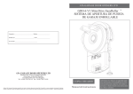
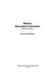
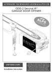
1
SmartSolar™
Solar Power Kits For Automatic Technology Openers
SmartPlanet
Solutions
TM
Part number # 13207
INSTALLATION INSTRUCTIONS | OWNERS COPY
WARNING: It is vital for the safety of all persons
to follow these instructions. Failure to comply
with the installation instructions and safety
warnings may result in serious personal injury
and/or property damage. Please save these
instructions for future reference.
Automatic Technology (Australia) Pty Ltd to the extent that such may be lawfully excluded hereby expressly disclaims all conditions or
warranties, statutory or otherwise which may be implied by laws as conditions or warranties of purchase of an Automatic Technology
(Australia) Pty Ltd Product. Automatic Technology (Australia) Pty Ltd hereby further expressly excludes all or any liability for any injury,
damage, cost, expense or claim whatsoever suffered by any person as a result whether directly or indirectly from failure to install the
Automatic Technology (Australia) Pty Ltd Product in accordance with these installation instructions.
2
SmartSolar™ Installation Instructions & Owners’ Manual
SmartSolar™
Solar Power Kits For Automatic Technology Openers
Important Safety Instructions
SmartSolar™ Features
Package Contents
Charger Board Layout
Installing the Solar Panel
Swing Gate Opener Set Up
Sliding Gate Opener Set Up
Overhead Door Opener Set Up
Roll Up Door Opener Set Up (GDO-6 EasyRoller®)
Roll Up Door Opener Set Up (GDO-8 EasyRoller®)
Specifications
Warranty
4
5
6
7
8
9
10
11
12
13
14
15
Installation Instructions & Owners’ Manual SmartSolar™
3
Important Safety Instructions
WARNING: It is vital for the safety of all persons to follow
these instructions. Failure to comply with the following
safety rules may result in serious personal injury and/or
property damage.
DO NOT short the output of batteries. Serious personal injury and/or property damage can result from failure
to follow this warning.
DO NOT connect battery wires incorrectly to solar charger - Observe the polarity carefully!
DO NOT connect any other source of power to the opener if a SmartSolar™ kit is installed.
DO NOT use the SmartSolar™ kit to power other devices - it is specifically designed for Automatic Technology
door and gate openers and some accessories only.
DO NOT handle damaged or leaking batteries.
DO NOT connect the battery box directly to solar panel.
DO NOT bend or drop the solar panel.
The solar charger and battery box unit should be installed away from sprinkler systems.
DO NOT immerse in water or spray directly with a hose or other device.
Install the solar charger kit in a location where it is out of reach of children.
The solar charger kit contains sealed lead-acid batteries that must be
disposed of properly at the end of their useful life.
During charging and discharging cycles the lead-acid batteries may
release explosive gases. Ensure that the area around the batteries is
well ventilated.
Take care not to allow any metal objects to make contact with the
positive and negative terminals. This will short circuit the battery
causing sparks and possible damage to the battery, the solar
charger module, or even cause an explosion.
Wear appropriate protective clothing and avoid touching
your eyes after working with batteries.
4
SmartSolar™ Installation Instructions & Owners’ Manual
SmartSolar™ Features
Thank you for purchasing the SmartSolar™ solar power kit
for Automatic Technology opener products. The unique
and exciting new technologies of SmartSolar™ makes cost
effective green or remote location automation a reality.
Using only quality components and materials, this product
will provide years of smart, simple and secure operation.
• Rugged 100% solid state circuitry, with a low component count, for robust operation and reliability
• Compatible with most DC powered Automatic Technology openers
• The only modification for use is removal of the opener’s mains transformer
• The specially designed charger module needs only a single solar panel to charge dual 12Vd.c. batteries
• As little as four hours of sunlight provides enough charge for normal residential operation
• The battery holds enough charge for night time operation, and up to three days of backup power
• Fully weather-sealed components
• Accessories such as P.E. Beams can be integrated with the opener for improved safety or convenience
• The charger module has an integrated diode to prevent reverse current
• The charger module will not overcharge the batteries, and, to extend the life of batteries, the unit will shut
down if the batteries’ voltage drops below 19V
• Batteries are charged with a maximum of one ampere to prevent overheating
• The SmartSolar™ comes with sealed, non-spill lead acid batteries
• A limiting system only allows a “trickle” voltage to be fed to the batteries when at full charge
SmartPlanet
Solutions
TM
SmartSolar™ kits are part of Automatic
Technology‘s SmartPlanet Solutions™ - our latest
innovations that make environmentally conscious
automation a possibility!
Installation Instructions & Owners’ Manual SmartSolar™
5
Package Contents
Solar Kit - Southern & Central (Fig. 01)
SmartSolar™
Solar Power Kits For Automatic Technology Openers
SmartPlanet
Solutions
Solar Panel - 20 Watt STP020-12/CB
1
Battery Pack (2 X 12Ah)
1
Charger Board (with harness)
1
TM
INSTALLATION INSTRUCTIONS | OWNERS COPY
fig 01
2.5 metre two core cable
1
Accessory pack
1
Instruction & Installation Manual
1
Solar Kit - Gate (Fig. 02)
SmartSolar™
Solar Power Kits For Automatic Technology Openers
SmartPlanet
Solutions
Solar Panel - 30 Watt STP030-12/Lb
1
Battery Pack (2 X 12Ah)
1
Charger Board (with harness)
1
2.5 meter two core cable
1
Accessory pack
1
Instruction & Installation Manual
1
TM
INSTALLATION INSTRUCTIONS | OWNERS COPY
fig 02
6
SmartSolar™ Installation Instructions & Owners’ Manual
Charger Board Layout
01
- SOLAR is used to connect ( - ) from solar panel to this charger board. Connect the black wire from solar
panel to this connector
02 SOLAR + is used to connect ( + ) from solar panel to this charger board.
Connect the red wire from solar panel to this connector
03 - BAT connects the ( - ) from the battery box to the charger board.
Connect the black wire from battery box to the connector
04 BAT+ connects the ( + ) from the battery box to the charger board.
Connect the red wire from battery box to the connector
05 Red wire from solar harness connects to this terminal input.
06 White wire from solar harness connects to this terminal input.
07 Yellow wire from solar harness connects to this terminal input.
08 Black wire from solar harness connects to this terminal input.
01
02
fig 03
03
04
05
06
07
08
Installation Instructions & Owners’ Manual SmartSolar™
7
Installing the Solar Panel
Step 1 - Unpack the Kit
Unpack the Battery Box and the Solar Panel and inspect
them for any damage in transit.
L°
Fig 04
α°
Town
Latitude
(L°)
Panel
Angle
(α°)
Hobart
42.5º S
57.5º
Melbourne
37.5º S
52.5º
35º S
50º
Sydney
33.5º S
48.5º
Newcastle, Broken Hill,
Port Augusta, Perth
32.5º S
47.5º
Brisbane, Oodnadatta,
Geraldton
27.5º S
42.5º
20º S
35º
5º
20º
Canberra, Adelaide,
Albany,
Fig 05
Townsville, Tennant
Creek, Port Herald
Darwin
8
SmartSolar™ Installation Instructions & Owners’ Manual
Step 2 - Mount the Solar Panel
1. Determine a mounting point for the solar panel
as close as possible to the intended opener. The
length of cable from solar panel to solar charger
must not exceed 5m.
2. The solar panel should be faced to the North for
maximum effect.
a. Solar panel output is directly proportional
to the amount of sunlight to which it is
exposed. Thus, the panel should be
positioned to the north due to Australia’s
southern location.
3. The angle to tilt the solar panel for maximum
exposure to the sun is determined by the following
equation (Fig. 04):
α° = L° + 15°
Where “α°” is panel’s tilt angle from the horizontal,
and “L°” is the latitude of the mounting location.
See Fig.05 for a list of pre-calculated panel angles
for major centres in Australia. Use the protractor on
the last page to adjust the solar panel’s angle.
Step 3 - Determine the Type of
Opener
1. If connecting to a swing gate
opener, proceed to page 9
2.
If connecting to a EasySlider®
sliding gate opener, proceed to
Page 10
3.
If connecting to a GDO-9
SecuraLift® overhead door
opener, proceed to Page 11
4.
If connecting to a GDO-6
EasyRoller® roll up door opener,
proceed to Page 12
5.
If connecting to a GDO-8
EasyRoller® roll up door opener,
Swing Gate Opener Set Up
SGO-1 Elite™, SGO-4 SecureSwing™ & SGO-4 SecureSwing S™
WARNING: Do not connect the batteries until
Step A5 is completed.
Step A4 - Mount the Charger Board
1. Unplug the Control Box from mains power.
2. Remove the Control Box’s cover, then remove the
transformer, EMC board (if fitted) and mains power
cable.
3. Mount the Charger Board “C” on the Control Box’s
base ”B” using four brass spacers and eight M4x8
screws marked “S” (supplied with cb19 solar box
part number 00606). See Fig. 06.Plug the Charger
Board’s three wire harness (red/yellow/black) into
the CB-19 board’s “SBY-3” connector (Fig. 07).
4. Plug the Charger Board’s one wire harness (white)
into the “24vac in” connector on CB-19 control
board (Fig. 07).
s
c
B
Fig 06
s
IMPORTANT WARNING: Do not connect battery
or solar panel polarity incorrectly - this will result
in serious damage to components.
Fig 07
Step A5 - Connect the Solar Panel
1. Feed the Solar Panel’s cable through the Control
Box’s grommet
2. Connect the red wire to the Charger Board’s
“SOLAR+” connector, and the black wire to the
“–SOLAR” connector (Fig. 08).
WARNING: During Step A6 the opener will
become active.
Fig 08
e
Whit
Yellow
Red
Red (From Ba
ttery)
ttery)
Black (From Ba
Red (From Solar P
anel)
Step A7 - Re-setup and Test the Opener
1. Select Menu 7 on the CB-19 control board, press
“SET”, select Sub Menu 7 (“Battery/Solar”) and
enable using the “OPEN” and CLOSE” buttons.
2. Setup travel limits and transmitters as per the CB19 instruction manual.
3. Press either “OPEN” or “CLOSE” buttons, or use a
transmitter to operate the gate.
4. Refit the Control Box’s cover.
olar Panel)
Black (From S
Step A6 - Mount & Connect the Battery
1. Mount the Battery Box close to the opener.
2. Feed the 2-core 18awg gauge cable (supplied)
through the Battery Box’s grommet.
3. Connect the red wire to the Battery Box’s “+”
terminal, and the black wire to the “–” terminal
(Fig. 9).
4. Feed the other end of the battery cable through
the Control Box’s grommet.
5. Connect the red wire to the Charger Board’s
“BAT+” connector, and the black wire to the “–
BAT” connector (Fig. 08).
ire
W
ck
ire
a
l
B
dW
e
R
Fig 09
Installation Instructions & Owners’ Manual SmartSolar™
9
Sliding Gate Opener Set Up
ESV-24 EasySlider® & ESV-24MS EasySlider®
PLEASE NOTE: CB-11 firmware must be v0.65 or
higher for SmartSolar™ compatibility
WARNING: Do not connect the batteries until
Step B5 is completed.
Step B4 - Mount the Charger Board
1. Unplug the drive unit from mains power.
2. Remove the main cover, then remove the
transformer, EMC board (if fitted) and mains power
cable.
3. Use accessory pack 02. Mount the Charger Board
inside the cover using four screws supplied in the
pack 02 (Fig. 10).
4. Plug the Charger Board’s three wire harness (red/
yellow/black) into the CB-11 board’s “SBY-3”
connector (Fig. 11).
5. Plug the Charger Board’s one wire harness (white)
into the “24vac in” connector on CB-19 control
board (Fig. 11).
Fig 10
IMPORTANT WARNING: Do not connect battery
or solar panel polarity incorrectly - this will result
in serious damage to components.
Fig 11
Step B5 - Connect the Solar Panel
1. Feed the Solar Panel’s cable through black grommet
which the mains power cord ran through
2. Connect the red wire to the Charger Board’s
“SOLAR+” connector, and the black wire to the
“–SOLAR” connector (Fig. 12).
WARNING: During Step B6 the opener will
become active.
e
Whit
Yellow
Red
Red (From Ba
ttery)
ttery)
Black (From Ba
Red (From Solar P
anel)
olar Panel)
Black (From S
Fig 12
ire
W
ck
ire
a
l
B
dW
e
R
Fig 13
10
Step B6 - Mount & Connect the Battery
1. Mount the Battery Box close to the opener.
2. Feed the 2-core 18awg gauge cable (supplied)
through the Battery Box’s grommet.
3. Connect the red wire to the Battery Box’s “+”
terminal, and the black wire to the “–” terminal
(Fig. 13).
4. Feed the other end of the battery cable through the
drive unit’s black grommet.
5. Connect the red wire to the Charger Board’s
“BAT+” connector, and the black wire to the “–
BAT” connector (Fig. 12).
Step B7 - Re-setup and Test the Opener
1. Select Menu 7 on the control board, press “SET”,
select Sub Menu 7 (“Battery/Solar”) and enable
using the “OPEN” and CLOSE” buttons.
2. Setup travel limits and transmitters as per the CB19 instruction manual.
3. Press either “OPEN” or “CLOSE” buttons, or use a
transmitter to operate the gate.
SmartSolar™ Installation Instructions & Owners’ Manual
Overhead Door Opener Set Up
GDO-9 SecuraLift®
PLEASE NOTE: Control board firmware must be
v1.32 or higher for SmartSolar™ compatibility
s
c
s
WARNING: Do not connect the batteries until Step
C5 is completed.
c
Step C4 - Mount the Charger Board
1. Unplug the drive unit from mains power.
2. Remove the screws and swing open the main cover
and remove the light diffuser.
3. Remove the transformer, EMC board (if fitted) and
mains power cable.
4. Use accessory pack 01 .Fix the Charger Board
“C” under the timing assembly using three M4x8
screws (Fig. 14) at the location marked “S”.
5. Plug the Charger Board’s three wire harness (red/
yellow/black) into the control board’s “SBY-3”
connector (Fig. 15).
6. Plug the Charger Board’s one wire harness (white)
into the control board’s “24vac in” connector on
(Fig. 15).
7. Plug the solar shunt (supplied) onto the control
board’s “J13” connector (Fig. 15) only if control
board is CB15. Do not use this “Solar Shunt” on
to “DCB03” control board. Only use black shunt to
Short two pins of JP1 connector marked “SOLAR”
on “DCB03” control board .
Fig 14
Solar
Shunt
Fig 15
IMPORTANT WARNING: Do not connect battery
or solar panel polarity incorrectly - this will result
in serious damage to components.
Fig 16
e
Whit
Yellow
Red
Red (From Ba
ttery)
ttery)
Black (From Ba
Step C6 - Mount & Connect the Battery
1. Mount the Battery Box close to the opener.
2. Feed the 2-core 18awg gauge cable (supplied)
through the Battery Box’s grommet.
3. Connect the red wire to the Battery Box’s “+”
terminal, and the black wire to the “–” terminal
(Fig. 17).
4. Feed the other end of the battery cable through the
drive unit’s black grommet.
5. Connect the red wire to the Charger Board’s
“BAT+” connector, and the black wire to the “–
BAT” connector (Fig. 16).
6. Refit the light diffuser and main cover.
Red (From Solar P
anel)
WARNING: During Step C6 the opener will
become active.
olar Panel)
Black (From S
Step C5 - Connect the Solar Panel
1. Feed the Solar Panel’s cable through black grommet
located on the top of the plastic drive unit cover.
2. Connect the red wire to the Charger Board’s
“SOLAR+” connector, and the black wire to the
“–SOLAR” connector (Fig. 16).
ire
W
ck
ire
a
l
B
dW
e
R
Fig 17
Installation Instructions & Owners’ Manual SmartSolar™
11
Roll Up Door Opener Set Up
GDO-6 EasyRoller®
WARNING: Do not connect the batteries until
Step D5 is completed.
Step D4 - Mount the Charger Board
1. Unplug the drive unit from mains power.
2. Disengage motor using manual release cord.
3. Remove the main cover, timing cover and light
diffuser, then remove the transformer, EMC board
and mains power cable.
4. Use accessory pack 02. Fix the Charger Board under
the timing cover using four M4x8 screws (Fig. 18).
5. Feed the four wire cable through the opening, then
connect the three wire harness (red/yellow/black)
into the control board’s “SBY-3” connector (Fig. 19).
6. Plug the one wire harness (white) into the control
board’s “24vac in” connector on (Fig. 19).
7. Plug the solar shunt (supplied) onto the control
board’s “J13” connector (Fig. 15) only if control
board is CB15. Do not use this “Solar Shunt” on
to “DCB03” control board. Only use black shunt to
Short two pins of JP1 connector marked “SOLAR”
on “DCB03” control board .
IMPORTANT WARNING: Do not connect battery
or solar panel polarity incorrectly - this will result
in serious damage to components.
Fig 18
Fig 19
Solar
Step D5 - Connect the Solar Panel
1. Feed the Solar Panel’s cable through black grommet
on the chassis.
2. Connect the red wire to the Charger Board’s
“SOLAR+” connector, and the black wire to the
“–SOLAR” connector (Fig. 20).
WARNING: During Step D6 the opener will
become active.
e
Whit
Yellow
Red
Red (From Ba
ttery)
ttery)
Black (From Ba
Red (From Solar P
anel)
olar Panel)
Black (From S
Fig 20
ire
k W ire
c
a
Bl
dW
Re
Step D6 - Mount & Connect the Battery
1. Mount the Battery Box close to the opener.
2. Feed the 2-core 18awg gauge cable (supplied)
through the Battery Box’s grommet.
3. Connect the red wire to the Battery Box’s “+”
terminal, and the black wire to the “–” terminal
(Fig. 21).
4. Feed the other end of the battery cable through the
drive unit’s black grommet.
5. Connect the red wire to the Charger Board’s
“BAT+” connector, and the black wire to the “–
BAT” connector (Fig. 20).
6. Refit the timing cover, main cover and light diffuser.
Fig 21
Step D7 - Re-setup and Test the Opener
1. Setup travel limits and code transmitters as per the
GDO-6 instruction manual.
2. Press either the “OSC” buttons, or use a transmitter
to operate the opener.
12
SmartSolar™ Installation Instructions & Owners’ Manual
Roll Up Door Opener Set Up
GDO-8 EasyRoller®
Step E4 - Insert the Solar Panel’s Wires
1. Unplug the drive unit from mains power.
2. Remove the controls cover and chassis enclosure,
then remove the transformer and EMC board.
3. Remove the mains power cable, then fit a rubber
gland to its hole in the chassis. Feed the Solar
Panel’s wires through this gland (Fig. 22).
4. Use accessory pack 03. Fill the transformer’s screw
hole by using the rubber washer, metal washer and
M6x10 screw (supplied).
Fig 22
WARNING: Do not connect the batteries until
Step E5 is completed.
Step E5 - Mount the Battery Box
1. Drill a 12.5mm hole in the chassis enclosure at the
location shown in (Fig. 23).
2. Fit a rubber gland to this hole.
3. Mount the Battery Box close to the opener.
4. Feed the 2-core 18awg gauge cable (supplied)
through the Battery Box’s grommet, and the
12.5mm hole in the opener’s chassis.
5. DO NOT CONNECT THE WIRES to the Charger
Board or battery terminals.
Fig 23
IMPORTANT WARNING: Do not connect battery
or solar panel polarity incorrectly - this will result
in serious damage to components.
WARNING: During Step E6 the opener will become
active.
Step E6 - Mount & Wire the Charger Board
1. Use accessory pack 03. Secure the adhesive mounts
to the Charger Board with cable ties. Affix the
Charger Board inside the chassis enclosure above
the 12.5mm drilled hole.
2. Unscrew and remove the four-wire harness from
the Charger Board. Replace with the two-wire (red/
yellow) harness, connecting wires as shown (Fig. 24)
3. Plug the two wire (red/yellow) harness into the control
board’s “24vac supply” connector.
4. Connect the red wire to the Charger Board’s
“SOLAR+” connector, and the black wire to the
“–SOLAR” connector (Fig. 24).
5. Connect the red wire to the Battery Box’s “+”
terminal, and the black wire to the “–” terminal
(Fig. 25).
6. Refit covers and chassis enclosures to the opener.
Fig 24
ire
k W ire
c
a
Bl
dW
Re
Fig 25
Step E7 - Re-setup and Test the Opener
1. Setup travel limits and code transmitters as per the
GDO-8 instruction manual.
2. Press either the “OSC” buttons, or use a transmitter
to operate the opener.
Installation Instructions & Owners’ Manual SmartSolar™
13
Specifications
SmartSolar™ Technical Specifications*
Garage Door
Slider
Swing Gate
Load Voltage
24
24
24
Load Continuous Current
3 - 5A
5A
5 - 10A
Number of Cycles per Day
10
10
10
Number Of Non Illumination Backup Working
Days
3
3
3
Solar panel average rated output generation
time per day (winter months)
4 hours
4 hours
4 hours
Average Cycle Time (Opening and Closing)
40 seconds
90 seconds
72 seconds
Max. Standby Current
- Without P.E. Beams
100mA
100mA
100mA
180mA
180mA
180mA
- With P.E. Beams
- With 2 x P.E. Beams
Average total consumption current per day
- Without P.E. Beams
- With P.E. Beams
260mA
2.75 - 3Ah
3.7Ah
3.4 - 4.4Ah
4.66 - 4.8Ah
5.55Ah
5.31 - 6.3Ah
- With 2 x P.E. Beams
Average total consumption current per hour
- Without P.E. Beams
- With P.E. Beams
7.23 - 8.23Ah
0.11 - 0.13A
0.16A
0.14 - 0.18A
0.194 - 0.2A
0.23A
0.22 - 0.26A
- With 2 x P.E. Beams
14
0.3 - 0.343A
Recommended storage battery capacity /
voltage
10.5Ah/24v
12Ah/24V
12 - 18Ah/24V
Wire Gauge and Length from Battery to
Charger board (max)
18AWG, 3m
18AWG, 3m
18AWG, 3m
Solar Panel Output voltage / current
18V / 1.19A
18V / 1.75A
18V / 1.75A
SmartSolar™ Installation Instructions & Owners’ Manual
Warranty and exclusion of liability
1. This warranty is an addition to any non-excludable conditions or warranties that are implied into this contract
by relevant statute, including the Trade Practices Act 1974 (Cwth).
2. Subject to all of the matters set out below, Automatic Technology Australia Pty Ltd (“ATA”) warrants:
SmartSolar™ kit for twelve (12) months from the date of purchase (specified in the sales docket receipt) as
free of any defects in material and workmanship.
3. This warranty applies only where the purchaser:
(a) immediately notifies ATA or the retailer of the alleged defect;
(b) returns the product to the retailer; and
(c) presents the relevant sales docket and this warranty document to the retailer to confirm the date
of purchase.
4. Except for this warranty, ATA gives no warranties of any kind whatsoever (whether express or implied),
in relation to the product, and all warranties of whatsoever kind relating to the product are, to the extent
permissible by statute, hereby excluded.
5. To the extent permissible by statute, ATA disclaims any liability of whatsoever nature in respect of any claim
or demand for loss or damage which arises out of:
a. accidental damage to or normal wear and tear to the product or to the product’s components;
b. any cost relating to damage resulting from wear and tear;
c. loss or damage due to theft, fire, flood, rain, water, lightning, storms or any other acts of God;
d. maximum operating force exceeding 15kg (150N) when moving the door or gate manually to the
open or closed position;
e. door surface area and/or weight exceeding 16.5m2 and 100kg respectively;
f.
residential gate weight exceeding 400kg;
g. door or gate not in safe and correct working order and condition;
h. evidence of unauthorised repairs;
i.
any cost relating to damage caused by misuse, negligence or failure to maintain the equipment in a
proper working order as per clauses (d) through (i);
j.
installation, adjustment or use which is not in accordance with the instructions set out in installation
instruction manual
k. attempted or complete modification or repairs to the product carried out by a person who is not
authorised or has not been trained by ATA to carry out such modification or repairs;
l.
faulty or unsuitable wiring of structure to which the product is fixed or connected;
m. damage caused by insects;
n. loss or damage to any property whatsoever or any loss or expense whatsoever resulting or arising
there from or any consequential loss;
o. any cost or expense arising due to manufacturer recall of any product;
p. any cost or expense due to negligence of the approved service provider;
q. installation of a residential garage door or gate opener in a commercial or industrial situation or a nonsingle residential dwelling.
6. ATA’s liability under this warranty is limited, at ATA’s absolute option, to replacing or repairing the product
which ATA, in its unfettered opinion, considers to be defective either in material and/or workmanship or to
credit the dealer with the price at which the product was purchased by the dealer.
7. This warranty does not extend to cover labour for installation.
8. This warranty is limited to Return-to-Base (RTB) repair and does not cover labour for on-site attendance.
9. This warranty is void if the Product is not returned to the manufacturer in original or suitably secure packaging.
10. This warranty is only applicable for repairs to the product carried out within Australia.
11. This warranty does not cover consumable items including globes, batteries and fuses.
12. This warranty is not transferable.
13. Where the Product is retailed by any person other than ATA, except for the warranty set out above, such
person has no authority from ATA to give any warranty or guarantee on ATA’s behalf in addition to the
warranty set out above.
Installation Instructions & Owners’ Manual SmartSolar™
15
© September 2007 Automatic Technology (Australia) Pty Ltd. All rights reserved. SecuraCode®, EasyRoller ®, EasySlider ®, SecuraLift ®, SecureSwing™, SecureSwing S™, SmartSolar™, SmartPlanet™ and Elite™
are trademarks and registered trademarks of Automatic Technology (Australia) Pty Ltd. No part of this document may be reproduced without prior permission. In an ongoing commitment to product
quality we reserve the right to change specification without notice. E&OE.
Automatic Technololgy (Australia) Pty Ltd
ABN 11 007 125 368
6-8 Fiveways Boulevard
Keysborough, Victoria, 3173, Australia
P 1300 133 944
+61 2 9722 5666 (International Enquiries Only)
E [email protected]
www.ata-aust.com.au
GARAGE DOOR OPENERS | GATE OPENERS | REMOTE CONTROL ACCESS SOLUTIONS