1
AUTOMATIC TECHNOLOGY AUSTRALIA PTY LTD
Elite
SWING GATE OPENER
OWNERS COPY
Installation Instructions
Warning: It is vital for the safety of persons to
follow all instructions. Failure to comply with the
installation instructions and the safety warnings may
result in serious personal injury and/or property and
remote control opener damage.
Please save these instructions for future reference.
CONTENTS
PAGE CONTENTS
4.....
5.....
6.....
7.....
9.....
9.....
10...
11...
12...
13...
14...
15...
17...
18...
19...
19...
20...
20...
21...
22...
IMPORTANT SAFETY INSTRUCTIONS
FEATURES
KIT CONTENTS
DRIVE UNIT INSTALLATION
INSTALLING DRIVE UNIT ARMS
INSTALLING MINIMUM SIDE ROOM KIT
MOUNTING CONTROL BOX
ELECTRICAL CONNECTION - SINGLE LEAF
ELECTRICAL CONNECTION - DUAL LEAF
SETTING OBSTRUCTION FORCE
CONTROL BOARD LAYOUT
MODE SELECTION
CODING TRANSMITTERS
ACCESSORIES
BATTERY BACK UP
OPERATING INSTRUCTIONS
TROUBLE SHOOTING
SPECIFICATIONS
PARTS LIST
WARRANTY AND EXCLUSION OF LIABILITY
Automatic Technology Australia Pty Ltd to the extent that such may be lawfully excluded hereby expressly disclaims all
conditions or warranties, statutory or otherwise which may be implied by laws as conditions or warranties of purchase of
an Automatic Technology Australia Pty Ltd Swing Gate Opener and Automatic Technology Australia Pty Ltd hereby
further expressly excludes all or any liability for any injury, damage, cost, expense or claim whatsoever suffered by any
person as a result whether directly or indirectly from failure to install the Automatic Technology Australia Swing Gate
Opener in accordance with these installation instructions.
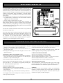
IMPORTANT SAFETY INSTRUCTIONS
Warning - It is vital for the safety of persons to follow all instructions. Failure to comply
with the following Safety Rules may result in serious personal injury and/or property damage.
For ADDITIONAL SAFETY protection we
STRONGLY recommend the fitting of a Photo Electric
Beam. In most countries Photo Electric Beams are
mandatory on all gates fitted with automatic openers.
For a small additional outlay ATA recommends that
Photo Electric Beams be installed with the
automatic opener ensuring additional safety and peace
of mind.
The opener is showerproof - it should not be immersed
in water or sprayed directly by a hose or other water
carrying device.
The gate(s) must be WELL BALANCED. and in good
working order. Faulty gates must be repaired by a
qualified technician prior to opener installation.
REMOVE OR DISENGAGE all gate locks and
mechanisms prior to installation of the opener.
DO NOT operate the gate opener unless the gate is in
full view and free from objects such as cars and
children/people. Make sure that the gate has finished
moving before entering or leaving the driveway.
Connect the gate opener to a properly EARTHED
general purpose 240V mains power outlet installed by a
qualified electrical contractor.
DO NOT operate the gate opener when
children/persons are near the gate. Children must be
supervised near the gate at all times when the gate
opener is in use. SERIOUS PERSONAL INJURY
and/or property damage can result from failure to follow
this warning.
DISCONNECT THE POWER CORD from mains
power before making any repairs or removing covers.
Only EXPERIENCED service personnel should
remove covers from the gate opener.
Keep hands and loose clothing CLEAR of the gate and
opener at all times.
DO NOT allow children to operate the gate opener.
Keep the remote control away from children. SERIOUS
PERSONAL INJURY OR DAMAGE can result from
failure to follow the instructions.
When using auto close mode a PHOTO ELECTRIC
BEAM must be fitted correctly and tested for operation
at regular intervals. EXTREME CAUTION is
recommended when using auto close mode. ALL
SAFETY RULES above must be followed.
Make sure that the SAFETY OBSTRUCTION
DETECTION system is working correctly, and is
TESTED every month. Test as per the Installation
Instruction Manual. Adjust if necessary and recheck.
Failure to follow this rule could result in SERIOUS
PERSONAL INJURY and/or property damage.
In order for the gate opener to SENSE an object
obstructing the gateway, some FORCE must be
exerted on the object. As a result the object, gate and/or
person may suffer DAMAGE or INJURY.
DO NOT disengage the gate opener to manual operation
with children/persons or any other objects including
motor vehicle within the gateway.
Make sure that the gate is fully open before driving into
or out of the driveway. And make sure the gate is fully
closed before leaving the driveway.
If using a key switch or keypad or any device that can
operate the gate opener, make sure it is out of reach of
children and that the gateway is in full view at all times.
The gate opener is not intended for use by young
children or infirm persons without adequate supervision.
Children should be supervised to ensure that they do not
play with the remote transmitters or the opener.
If the power supply cord is damaged, it MUST be
replaced by an ATA service agent or suitably qualified
person.
Frequently examine the installation, in particular hinges
and mountings for signs of wear, damage or imbalance.
DO NOT use if repair or adjustment is needed since a
fault in the installation or an incorrectly balanced gate
may cause injury.
Make sure that remote controls are kept out of reach of
children.
PLEASE READ THIS INSTRUCTION MANUAL FULLY BEFORE ATTEMPTING TO INSTALL
OR USE THE OPENER. FAILURE TO COMPLY WITH THE INSTALLATION INSTRUCTIONS
MAY RESULT IN SERIOUS INJURY AND/OR PROPERTY DAMAGE.
4
FEATURES
Thank you for purchasing the ATA Elite
Swing Gate Opener. This opener is
designed to suit residential hinged swing
gates. The components and materials used
in this opener are of the latest technology
and highest quality. Listed below are some
of the many features.
DUAL LEAF GATE
A dual leaf gate can be controlled with the
addition of a second drive unit. Mains
power is only required for the control box
and a 5-core low voltage cable for the
drive units.
OPERATION
To activate the gate simply press a button
on the remote control transmitter, keypad
or activate any other input device such as
key switch, loop detector, etc. During an
open or close cycle the gate can be stopped
by pressing the button while it is in
motion. The next actuation will move the
gate in the opposite direction.
HOPPING CODE TRANSMITTERS
Every time a button pressed on the
SecuraCode® transmitter a new access
code is generated at random from over
4.29 billion combinations. This greatly
enhances the security of the system and
makes code “grabbing” a thing of the past.
SECURITY CODE STORE
The Elite Swing Gate Opener uses state of
the art technology in storing your selected
transmitter codes. Up to thirty (30)
transmitters can be stored in the opener’s
memory.
ISS (INTELLIGENT SAFETY
OBSTRUCTION SYSTEM)
The opener will automatically reverse if
the gate hits an obstacle or be restricted in
some manner while it is performing a close
cycle. The amount of force the gate should
encounter
before
reversing
is
automatically adjusted by the control
system during the initialisation of the
automatic opener. The gate will also stop if
restricted whilst opening. The Safety
Obstruction Force should be checked at
least once a month.
CONTROLLING INPUTS
The control board has provision for
ancillary controlling inputs including:
open, close, stop, O/S/C, swipe, pedestrian
access and photo-electric (P.E.) safety
beams.
The opener can be triggered by devices
such as swipe card, inductive loop
detector, key switch, hard wired switch,
keypad, etc.
PEDESTRIAN MODE
The gate can be programmed to open
partially to allow pedestrian access. In a
dual leaf gate only one leaf opens to allow
pedestrians through without permitting
vehicle access.
CONTROL OF LOCK AND LIGHTS
The incorporated controller has dedicated
outputs for operating an electric lock and
warning or courtesy lights (with the
addition of a light relay module). The
timing of these outputs can be adjusted to
suit your needs.
5
PROGRAMMABLE PHOTO
ELECTRIC BEAM INPUT
The PE Beam input can be programmed to
either stop or reverse the gate during a
close cycle. The gate opener can also be
programmed to prevent the gate moving
without the PE first being triggered.
AUTO-CLOSE MODE
The gate can be closed automatically after
preset time. Auto-close mode can be active
for full or pedestrian access or via the
triggered PE input. A PE Beam must be
fitted to use this function.
BATTERY BACKUP AND SOLAR
OPERATION
The opener can be fitted with optional
battery backup or solar chargers to provide
operation during power outages or at
unpowered sites.
GATE SYNC/DELAY
If the gate leafs overlap, a delay can be
used to start one leaf moving without
interfering with the other.
SOFT STOP
The opener slows as the close limit is
approached to reduce the chance of heavy
contact and causing damage to both gate
and opener.
MANUAL OPERATION
The opener can be disengaged and the gate
operated manually by opening the drive
unit cover and disengaging the gearbox. If
power to the opener is disrupted for any
reason it can be disengaged. This will
allow you to manually open or close the
gate.
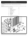
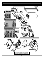
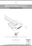
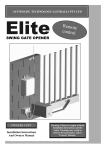
Kit Contents
CONTROL BOX
The control box contains the control board, capable of driving either a single or dual leaf gate, a remote control receiver and
transformer. When used with suitable cable glands, it is designed to meet the IP56 weather proof rating.
DRIVE UNIT
The Drive Unit consists of a 24V DC motor, a rugged gear box and a cam activated limit switch assembly. Each drive unit is supplied
with a pair of arms, arm bracket plus arm assembly hardware.
ITEM
1.
2.
3.
4.
5.
6.
7.
8.
9.
10.
11.
12.
13.
14.
DESCRIPTION
Drive Unit
Control Box
Control Box Mounting Bracket
PTX-4 Keyring Transmitter
Transmitter Battery
Drive Arm Extension
Slave Arm
Gate Mounting Bracket
Plastic Washer
Shoulder Screw
Hex. Head Screw
Spring Washer
Flat Washer
Antenna (with cable & mounting bracket)
QTY
1
1
4
2
2
1
1
1
4
2
2
2
2
1
FIG. 1
6
DRIVE UNIT INSTALLATION
The ATA Elite swing gate opener is designed to operate most
residential swing gates. The gates must be in good working
condition and should operate by hand relatively freely. Wind
loading may affect the operation of the opener in high wind areas.
Correct obstruction and reversing settings should be chosen for
trouble free operation.
2. The pier or post for mounting must be of solid construction
(Brick, solid timber or steel). It must bare most of the force
applied by the drive unit.
3. A weatherproof 240V 10A general purpose power point
should be available within one metre of the pier/post.
4. If dual gate openers are required, provision for underground
cabling should be made from one post to the other.
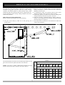
5. Side room clearance is adequate. Refer to Table 1 and Fig. 2.
If there is not enough side room available, the Minimum Side
Room Kit (Page 9) is required.
6. The mount distance of the Drive Unit should be recorded. This
value will be used later.
PRE-INSTALLATION INSPECTION
Before commencing installation check the following:
1. The gate moves freely by hand for it’s full opening and
closing travel.
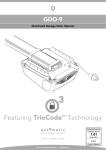
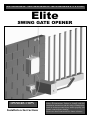
FIG. 2
TABLE 1
NOTE: If the gate is already installed then measure the hinge
distance and use this table to optimise the mount distance.
HINGE DISTANCE
MOUNT
DISTANCE
The mount distance for the drive unit and the hinge distance for the
gate can be selected to optimise the side room clearance.
0
90
470
470
470
470
470
470
465
460
120
450
470
480
470
465
460
435
425
140
470
465
470
465
460
440
420
390
200
470
465
445
430
400
350
390
250
50
100
125
150
180
220
SIDE ROOM CLEARANCE
All dimensions are in mm
7
200
DRIVE UNIT INSTALLATION
MOUNTING DRIVE UNIT
1. Mount drive unit using four (4) 10mm loxins or dynabolts.
2. Make sure that the Drive Unit is mounted at an appropriate
height from the ground - allow minimum 35mm clearance for
drive arm extension.
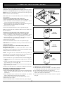
FIG. 3
PULL RING TO
DISENGAGE MOTOR
NOTE: If the gateway slopes away from pier/post make sure an
allowance is made for clearance of the drive arm extension and
slave arm to not touch the ground.
MANUAL OPERATION
Disengage drive motor by pulling manual release pin up using the
release ring. While holding the ring, rotate the motor
assembly clockwise. (Fig. 3 & 4)
To re-engage pull pin and rotate motor assembly anti-clockwise
until manual release pin clicks into place.
FIG. 4
DISENGAGED
ENGAGED
8
INSTALLING DRIVE UNIT ARMS
FIG. 5
AFFIXING ARMS AND BRACKETS TO GATE
1. Position gate in close position.
2. Attach drive arm extension to drive arm (fixed to the drive
unit) (Fig. 1), using two (2) Hex. Head screws and spring and
flat washers supplied.
3. Attach slave arm to drive arm extension using plastic
washers and shoulder screw supplied. (see Page 6).
4. Assemble Gate Mounting Bracket and Slave Arm using
shoulder screw and plastic washers, do not tighten yet.
5. Extend arms out straight and mark position where the Gate
Mounting Bracket touches gate (Fig. 5).
6. From this mark, measure 10mm toward Drive Unit and mark
again. This is where Gate Mounting Bracket will be mounted.
7. Remove the Gate Mounting Bracket from the Slave Arm and
secure the Gate Mounting Bracket to the gate at second mark.
8. Reassemble Slave Arm to Gate Mounting Bracket using
shoulder screw and plastic washers. Secure firmly.
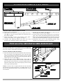
INSTALLING MINIMUM SIDE ROOM KIT
If you have limited side room, an optional drive arm modification
kit reduces the gate opener’s required side room to the width of the
drive unit (135mm). (ATA Order code 90182).
FITTING MINIMUM SIDE ROOM KIT
1. Secure the extension arm from the minimum side room kit onto
drive arm extension with supplied M12 screws. Drill Ø12 hole
in Drive Arm Extension (use hole in extension arm as a guide).
Insert other M12 screw and secure with spring washer and nut.
Check that screws are tight (Fig. 7).
2. Check that Drive Unit is DISENGAGED AND GATE IS
CLOSED. Slide the Guide Track over idler. Locate Track on
gate and check travel of the Arm. The idler should always be
inside the Guide Track in the closed and open positions. Secure
track to gate (weld if possible).
NOTE: If a shorter arm is required, drill the drive arm extension
and extension arm where appropriate, you should not have to cut
the arms and should still be able to use pre-threaded hole in drive
arm extension.
9
FIG. 6
FIG. 7
MOUNTING CONTROL BOX
MOUNTING CONTROL BOX
FIG. 8
CAUTION: DO NOT USE ANY CABLES WHICH CARRY
GREEN/YELLOW WIRES AS THIS SIGNIFIES EARTH,
AND DOES NOT COMPLY WITH ELECTRICAL
AUTHORITY REGULATIONS.
The control box should be mounted near the drive unit using four
(4) 6mm screws.
1. Drill holes as per (Fig. 8). When locating the control box allow
ample space around the unit for easy access and wiring
connections.
2. Remove cover from control box.
3. Determine which leaf you would like to open first and close
last. This gate leaf must be connected to Motor 1 (M1) terminals
on the control board. Connect drive unit(s) to control board
using 5-core cable. For detailed electrical connection (see
pages 11 & 12).
Note: To determine left or right hand installation stand inside the
driveway. looking out to the street.
ANTENNA
Mount the antenna at or above the height of the gate or fence for
optimal reception, which ever is higher. (Fig. 8). Do not cut
antenna or coaxial cable.
FIG. 9
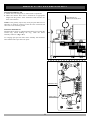
LIMITS AND CAMS SET-UP
Setting of limits for open and closed position is performed with
opener in manual position (Fig. 3 & 4).
WARNING: DO NOT SWITCH POWER ON OR ENGAGE
MOTOR DRIVE.
For Right AND Left Hand Side installation:
1. When gate is CLOSED turn TOP cam in a clockwise direction
(Fig. 9) until an audible click can be heard from the TOP
micro-switch.
2. Open the gate to the required OPEN position and turn LOWER
cam in an anticlockwise direction until a click can be heard
from LOWER micro switch.
10
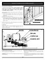
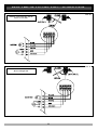
ELECTRICAL CONNECTION - SINGLE LEAF
FIG. 10
SINGLE LEAF INSTALLATION
Motor on Left Side
FIG. 11
SINGLE LEAF INSTALLATION
Motor on Right Side
11
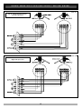
ELECTRICAL CONNECTION - DUAL LEAF
FIG. 12
DUAL LEAF INSTALLATION
Left side opens first
FIG. 13
DUAL LEAF INSTALLATION
Right side opens first
12
SETTING OBSTRUCTION FORCE
CHECKING LIMITS POSITIONS
WARNING: If gates require sync delay - Switch 1 must be set to
ON before fine tuning limits.
1. Re-engage drive units.
2. Press OSC to move gate until the limit switch engages.
3. Fine tune limts cam positions so that the gate reaches the
desired open and closed positions.
NOTE: In the pre-initialised state the OSC button moves the gate
only while depressed.
INITIALISATION
1. Engage the motor assembly (Fig. 3 & 4), switch power on at
power point. Replace drive unit cover and lock in place.
2. Close the gate(s) if it is not already closed, by holding down
the OSC button. Once the gate(s) is in the fully closed
position release OSC button. The Red LED should be
steady ON.
3. Press the Reset button on the control board for about two
seconds then release. The gate(s) should start opening. When
the gate(s) reaches the fully open position it will pause and
start to close. When the gate(s) returns to the fully closed
position the initialisation is complete. The controller is now
ready for normal use.
IMPORTANT NOTICE:
Intialising must be performed for the gates obstruction sensors to
be correctly calculated and to set the soft stop feature.
NOTE: The OSC button is the only input which will function
prior to the controller being initialised using the above procedure.
SYNCHRONISED OVERLAPPING GATE LEAFS
When dual swing gates are used it is common for a back stop to
be mounted on one of the gate leafs so that the leafs are aligned
when closed. To prevent the gate leafs from interfering with each
other, the gate leaf with the back stop must reach the close
position first when closing and open last.
SETTING OVERLOAD SENSITIVITY
The overload sensitivity is adjustable using the OVERLOAD dial.
Position 0 making it easy to overload a motor, increasing through
positions 1 to 8, with position 9 being the hardest. To set, turn the
dial to the desired number to manually increase or decrease the
overload sensitivity.
Set “SYNCHRONISING DELAY” dip-switch to “ON” position.
This will result in the M1 starting to open 2 seconds before M2
and M2 starting to close 2 seconds before M1.
Standard default is - 5. Areas prone to high wind may require a
slight increase.
Note:If a lock is to be fitted to the gate, it should be mounted on
the leaf driven by M1. If the delay of 2 seconds is not suitable it
can be altered, see sections SYNCHRONISING DELAY TIME.
on page 16.
INITIALISING OBSTRUCTION FORCE
WARNING: Make sure that the obstruction sensitivity is
adjusted correctly so that, when obstructed with minimum
pressure, the gate(s) reverse to the open position and stops on
opening cycle.
In order for the controller to slow the motors down at the correct
position and to automatically detect overloads, it needs to record
the normal cycle time of each motor in each direction and also
sample each motors normal running time. If the gate(s) is stopped
for some reason during step 2 below, then simply restart the
process. While the open and close cycles are underway, the
control board will not slow the motors and the overload detection
is disabled.
NOTE: The gate will exert some force before obstruction sensing
activates. Too light a setting will cause nuisance stopping when
gate starts to age or resistance occurs in gate track rollers or
hinges. Too heavy a setting may cause serious personal injury
and/or property damage.
WARNING: Force adjustment must be set correctly and tested
upon completion of installation. The gate should be tested
periodically to ensure correct operation and adjustment made as
required. The opener must not be used if force setting is incorrect
or inoperative.
NOTE: Whenever the limit cams are adjusted the safety
obstruction system must be cleared and re-initialised as travel
distance may have changed.
MOTOR SPEED CONTROL
At the start of the gate’s cycle the selected motor speed is set
using the SPEED dial with 0 being the slowest and 9 being the
fastest. The motor will be driven at this speed until it nears the end
of the travel, at which time it will be slowed down. The motor
slows down to the speed represented by '3' on the speed dial.
NOTE: Setting the dial to 3 or lower will negate the soft stop
function.
In order for the controller to determine when to slow the motors
down towards the end of its cycle, a complete open and close
cycle must be performed and the travel times of each motor in
each direction established (i.e. initialisation).
To adjust the slow motor speed refer to page 16.
13
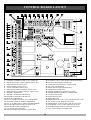
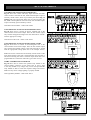
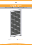
CONTROL BOARD LAYOUT
FIG. 14
1. COMMON TERMINAL FOR (2) TO (7) BELOW.
2. PHOTO-ELECTRIC SAFETY BEAM INPUT (N/C).
3. OPEN CONTROL INPUT (N/C).
4. STOP CONTROL INPUT (N/C).
5. CLOSE CONTROL INPUT (N/O).
6. OPEN/STOP/CLOSE CONTROL INPUT (N/O).
7. PEDESTRIAN ACCESS CONTROL INPUT (N/O).
8. MOTOR 1 TERMINALS.
9. MOTOR 1 LIMIT SWITCH INPUTS.
10. MOTOR 2 LIMIT SWITCH INPUTS.
11. MOTOR 2 TERMINALS.
12. 24V DC SUPPLY OUTPUT (TO ACCESSORIES).
13. ELECTRIC LOCK CONTROL TERMINALS.
14. 24V AC SUPPLY INPUT (FROM TRANSFORMER).
15. BACKUP BATTERY SUPPLY IN USE L.E.D.
16. BACKUP BATTERY TERMINALS.
17. VACATION SHUNT & PINS.
18. SECURA-LIGHT INTERFACE CONNECTOR.
19. ANTENNA (ONLY USED WITH 27MHz RECEIVER).
20. PLUG-IN RECEIVER CONNECTOR.
21. LIGHT RELAY INTERFACE CONNECTOR.
22. P.E., OPN, STP SHUNTS.
23. MODE SELECTION DIPSWITCHES.
24. SPEED SELECTION DIAL.
25. MOTOR OVERLOAD SENSITIVITY DIAL.
26. PROGRAMMER INTERFACE CONNECTOR.
27. CLOSE STATUS LED.
28. OPEN STATUS LED.
29. RESET BUTTON.
30. PEDESTRIAN ACCESS CYCLE TIMER SET BUTTON.
31. P.E. AUTO-CLOSE TIME SET BUTTON.
32. PEDESTRIAN AUTO-CLOSE TIME SET BUTTON.
33. STANDARD AUTO-CLOSE TIME SET BUTTON.
34. SYNCHRONISING DELAY TIME SET BUTTON.
35. OSC - OPEN/STOP/CLOSE BUTTON.
14
MODE SELECTION
AUTO-CLOSE MODE
Auto-close mode automatically closes the gate after a preset time
once the gate has reached its desired open position. The controller
starts to close the gate when the count down has expired. The
timer can be suspended by activating a suspending input (which
inputs 'suspend' depends on which auto-close mode is selected).
When the input is deactivated the auto-close timer is reset and the
count down recommenced. Auto-close functions are temporarily
disabled by certain actions. When this happens the controller will
not auto-close the gate until the user performs some action to
re-enable the function. Details about the three auto-close modes
follow.
STANDARD AUTO-CLOSE
This mode is selected by placing the mode selection switch
labeled “STANDARD AUTO-CLS” into the “ON” position.
When selected the gate will auto-close 30 seconds after being
fully opened. The following gives details about this auto-close
mode.
Auto-closes after being:
z Fully opened. (except when the gate is reversed to the open
position after a motor overload is detected while closing)
Countdown suspended by:
z The P.E. input being active.
z The OPN input being active.
Function temporarily disabled by:
z Activating the STP input while the gate is open.
z A motor overload causing the gate to reverse open.
Function re-enabled by:
z Activating the OPN input while the gate is open.
z Activating the OSC input, in SWIPE mode, while the gate is
open.
z By activating any input which cases the gate leaf to start to
close. The auto-close function will then be enabled once the
gate is re-opened.
The standard delay time of 30 seconds can be altered, see
STANDARD AUTO-CLOSE DELAY TIME, on page 16.
PEDESTRIAN ACCESS AUTO-CLOSE.
This mode is selected by placing the mode selection dip-switch
labeled “PEDESTRIAN AUTO-CLS” into the “ON” position.
When selected, the gate leaf will auto-close 15 seconds after
being opened for pedestrian access.
Auto-closes after being:
z Driven to the programmed pedestrian access position. (Except
when the gate leaf is reversed after a motor overload is
detected.) Reversing during pedestrian access is only
implemented when special PED modes are selected.
Stopped by the P.E. input when closing after pedestrian access
(standard PED mode only).
Countdown suspended by:
z The P.E. input being active.
z The PED input being active.
Function temporarily disabled by:
z Activating the STP input while the gate leaf is in the
programmed pedestrian access position.
z Activating the STP input in condition 2 of 'Auto-closes
after being above.
z A motor overload causing the gate to reverse back to the
programmed pedestrian access position. (Reversing during
pedestrian access is only implemented when special PED
modes are selected.)
Function re-enabled by:
z Activating the PED input, in SWIPE mode, while the gate is in
the programmed pedestrian access position. Activating the
PED input and causing the gate leaf to start to close.
The standard delay time of 15 seconds can be altered, see section
PEDESTRIAN ACCESS AUTO-CLOSE DELAY TIME on page
16.
z
P.E TRIGGERED AUTO-CLOSE
This mode is selected by placing the mode selection dip-switch
labeled “P.E. TRIGGERED AUTO CLS” into the “ON” position.
When this auto-close mode is selected, the gate will auto-close
after the P.E. input has been activated and released since:
1. The gate was last closed
2. The P.E. triggered auto-close function
was re-enabled after being disabled.
3. The SWIPE input was activated.
Auto-closes after the P.E. input has been activated and then
released and the gate:
z Is fully opened. (except when the gate is reversed to the open
position after a motor overload is detected while closing).
z The gate has been stopped by the P.E. input.
Countdown suspended by:
z The P.E. input being active.
z The OPN input being active.
Function temporarily disabled by:
z Activating the STP input.
z A motor overload causing the gate to stop or reverse open.
Function re-enabled by:
z Activating the OPN input while the gate is open.
z Activating the SWIPE input.
z By activating any input which cases the gate to start to open or
close. The auto-close function will then be enabled once the
gate is re-opened or the P.E. input causes the gate to stop.
15
MODE SELECTION
If the P.E. input is configured to stop the gate during opening or
closing, then the gate can auto-close from a midway position. This
feature is implemented so that once a vehicle has entered the gateway and broken the P.E. beam, the gate will stop. When the P.E.
beam is cleared the gate will auto-close from the stopped position.
This results in the gate not having to fully open and thus reducing
the time unwarranted access through the gate is possible. The
factory set delay time of 1 second is adjustable, see section “P.E.
TRIGGERED AUTO-CLOSE DELAY TIME” below.
MIXING AUTO-CLOSE MODES
The PEDESTRIAN AUTO-CLS mode and the STANDARD
AUTO-CLS mode do not affect each other as one operates during
standard operation and the other during pedestrian access.
However it is possible to have P.E. triggered pedestrian auto-close
by selecting both the PEDESTRIAN AUTO-CLS and P.E.
TRIGGERED AUTO-CLS modes. In this case the gate would
partly open for pedestrian access and then either the P.E.
TRIGGERED AUTO-CLS would cause the gate to auto-close
when a pedestrian walks through and activates the P.E beam or, if
no one walked through the PEDESTRIAN AUTO-CLS would
close the gate. This way the gate is only kept open long enough
for a person to walk through, but with the backup that if no one
walks through the gate will still close. The same concept can be
used with standard operation by selecting both the STANDARD
AUTO-CLS and the P.E. TRIGGERED AUTO-CLS modes. That
is, the gate would only stay open long enough for the vehicle to
pass through but would still auto-close if no vehicle enters.
Note: P.E. TRIGGERED AUTO-CLS will not operate during
pedestrian access unless the PEDESTRIAN AUTO-CLS mode is
also selected.
MODE SETTING ADJUSTMENT
This section describes how to adjust several parameters via the
control boards buttons and dials. Other adjustments can be
performed by use of the advanced technicians Control Board
Instruction Manual and Programmer. Contact your local ATA
dealer for a copy.
3. When the gate leaf has reached a position suitable for
pedestrian access, release the button.
4. The pedestrian access drive timer has now been set. Either
press the OSC button and exit the time set mode or continue
setting one of the synchronising delay or auto-close times.
SYNCHRONISING DELAY TIME
The synchronising delay time is adjusted using the 'SYNC delay
timer' button. The synchronising delay time is adjustable in 0.1
second steps. The factory set default is 2 seconds.
SLOW MOTOR SPEED
IMPORTANT: Please make sure that the gate(s) are in the open
position before proceeding with steps 1 to 5 below.
The speed the motor slows down towards the end of a cycle can
be adjusted using the following procedure. The factory set
default slow speed is set to “ 3”
1. Note the current maximum speed selected by the speed
selection dial.
2. Using the speed selection dial select the desired slow speed.
3. Press and hold the 'RESET' button and count five (5) flashes of
the OPEN status led.
4. Release button.
5. Place the speed selection dial back to the desired maximum
speed .
STANDARD AUTO-CLOSE DELAY TIME
The standard auto-close delay time is adjusted using the 'STD
auto-close' button. Delay time is adjustable in 1 second steps. The
factory set default is 30 seconds.
PEDESTRIAN ACCESS AUTO-CLOSE DELAY TIME
The pedestrian auto-close delay time is adjusted using the 'PED
auto-close' button. Delay time is adjustable in 1 second steps. The
factory set default is 15 seconds.
P.E. TRIGGERED AUTO-CLOSE DELAY TIME
The P.E. triggered auto-close delay time is adjusted using the
'P.E. auto-close' button. Delay time is adjustable in 1 second steps.
The factory set default is “off”.
PEDESTRIAN ACCESS CYCLE TIME
The pedestrian access cycle time sets how far gate leaf 1 opens for
pedestrian access.
1. Drive the gate to the closed position using the OSC button or
another control input.
2. Press and hold the 'PED cycle timer' button. The gate leaf
driven by motor 1 will start to open.
ADJUSTING AUTO-CLOSE AND SYNC DELAY TIMES
1. Press and hold the required button for the desired time.
2. Release button.
3. Press the OSC button to exit the time setting mode or restart
from step 1 to set another time.
Notes:
a) The time setting mode is indicated by both the OPEN and
CLOSE status LED's being off.
b) Each flash of the OPN led represents 1 second.
c) When a button is first pressed, the CLOSE status LED turns
on. The time delay is set to zero when the CLOSE LED turns
off and then increases for as long as the button is held.
16
CODING TRANSMITTERS
CODING TRANSMITTERS INTO RECEIVER
Transmitters can be programmed into the gates receiver to do two
functions: the full Open/Stop/Close cycle, and partly open gate for
PEDestrian access. The memory in the receiver can store up to 30
different remote control transmitters.
FIG. 15
Note: Make sure to connect the battery to the transmitter in the
correct polarity.
STORING TRANSMITTER CODE FOR O/S/C
1. Press and hold the SW1 button on the receiver (Fig. 15).
2. Press the button on the transmitter you would like to use to
control the gate for approximately two seconds.
3. Release. Pause for two seconds. Press the same button again on
the transmitter for approximately two seconds.
4. Release the SW1 button.
5. Press the transmitter button to test if it operates the gate.
Note: If required, all four transmitter buttons can be coded to do
the same function.
FIG. 16
PRESS
Existing
Transmitter
STORING TRANSMITTER CODE FOR PED ACCESS
1. Press and hold the SW2 button on the receiver (Fig. 15).
2. Press the button on the transmitter you would like to use to
control the pedestrian access for approximately two seconds.
3. Release. Pause for two seconds. Press the same button again on
the Transmitter for approximately two seconds.
4. Release the SW2 button.
5. Press the Transmitter button to see if it operates the gate.
FIG. 17
IMPORTANT: The Pedestrian Access Cycle Time must be set to
to activate this feature.
Existing
Transmitter
STORING ADDITIONAL TRANSMITTER(S) FROM A
REMOTE LOCATION
Using this method you do not need to have direct access to the
control box or receiver. However, you do need a transmitter that is
already coded to the controller’s receiver.
NOTE: The gate must be activated when the step below is
performed. The moving gate confirms that the correct button was
pressed and the transmitter is in range of the opener.
1. Press the button on a pre coded transmitter and release (Fig. 16).
2. Using a small pin press and hold the coding hole for 2 seconds
(Fig. 17).
3. Within 10 seconds press the button on the new transmitter for
approximately two seconds (Fig. 18).
4. Release. Pause for two seconds. Press the same button again for
approximately two seconds.
5. Wait ten seconds and test to confirm that coding was successful.
DELETING STORED TRANSMITTER CODES
TO DELETE ONE TRANSMITTER
1. Press and hold the SW1 button on the receiver. (Pressing SW2
button will only delete PED function and not OSC for that
transmitter).
2. Press the button (one of four) on the transmitter you would
like to delete from the receiver for two seconds.
3. Pause for two seconds. Press the same button again 2 secs.
4. Release the SW1 button.
5. Press transmitter button to confirm it does not operate the gate.
17
FIG. 18
PRESS
New
Transmitter
TO DELETE ALL TRANSMITTERS
1. Turn off mains power at the switch - if the battery backup
is connected, remove the VAC shunt (replace after step 4).
2. Press and hold the SW1 button on the receiver.
3. Turn on the mains power and continue to hold the SW1
button until status LED illuminates.
4. Press any transmitter button to confirm it does not operate
the gate.
ACCESSORIES
CONTROL AND SAFETY INPUT TERMINALS
Fig. 19 shows the control and safety input terminals and their
switch contacts. Note that the P.E., OPN and STP inputs require a
normally closed contact, which is provided by the shunts (Fig. 14
and Fig. 19). The appropriate shunt must be removed when the
P.E, OPN or STP inputs are used. The CLS, OSC and PED inputs
require a normally open momentary contact.
FIG. 19
ATA Photo Electric Beam - Order Code: 90214
LOCK RELEASE OUTPUT FOR SOLENOID LOCKS
Fig. 20 shows how to connect an electric solenoid lock to the
control board’s lock release output. Note the lock release output
only switches the applied voltage to the lock and must be “wetted”
with the appropriate voltage.
FIG. 20
ATA Electric Pulse Lock - Order Code: 90101.
LOCK RELEASE OUTPUT FOR MAGNETIC LOCKS
Fig. 21 shows how to connect an electromagnetic lock to the
control board’s lock release output. Note the lock release output
only switches the applied voltage to the lock and must be wetted
with the appropriate voltage (24V DC in the example shown).
Note: The lock is connected to the normally closed contact of the
lock release output as the lock is energised when the controller is
idle and not driving the motors. The lock output action has to be
programmed for a hold action when this type of lock is used.
FIG. 21
LIGHT CONTROL RELAY MODULE
Fig. 22 shows how to connect the optional relay module to the
control board’s connector. It also shows how to wire a light
to the relay module. Any voltage relay can be used provided the
relay module is able to switch the required voltage and current.
Make sure any mains voltage lighting is properly earthed.
ATA Light Relay Module - Order Code: 90111.
FIG. 22
18
BATTERY BACK UP
An optional battery backup system is available so that the gate can
be operated (for a limited time) in the event of mains power failure.
When the backup system is utilised, the control board detects the
presence of mains voltage. If mains power fails the control board
switches to the backup supply provided by a 24V DC battery.
When mains power is restored the control board switches back to
mains supply.
The following items are required to use the battery backup system:
1. A 24VDC battery connected to the control board connector
(Fig. 23). ATA order code 90230
2. Ensure a shunt is placed on the VAC pins.
The control board has a built in charger which maintains the
battery charge when mains power is present. The control board
monitors the battery voltage during use and prevents discharging,
which damages the battery, by shutting down the control board if
the battery voltage gets too low.
FIG. 23
SHUNT
IN USE
INDICATOR
24V DC
TERMINAL
The 'IN USE' indicator illuminates when mains is not present and
the battery is being used.
The 'VAC' shunt can be removed to prevent the battery system
being used when mains power fails. The battery charge is still
maintained provided mains is present. This link is provided so that
the controller can be turned off when a backup battery is
connected. It is removed when complete absence of power is
required e.g. when clearing the receivers memory.
OPERATING INSTRUCTIONS
OPERATING THE GATE OPENER - O/S/C
z Press the Button on the Transmitter programmed for full gate
opening for two seconds to open or close the gate.
z Pressing the Transmitter Button again during operation will
cause the gate to stop.
z Pressing the button again will cause the gate to move in the
opposite direction.
OPERATING THE GATE OPENER - PED
z Press the button on the transmitter programmed for pedestrian
access and the gate will open partially. Or in a dual leaf gate
installation - only one leaf will open.
z Press the button again and the gate will close.
When an Auto Close mode selection switch is “ON” the gate will
auto close after 15 – 30 seconds or as triggered by breaking the
P.E. Beam and commencing the timer.
MANUAL OPERATION
Remove black drive unit cover (key required).
z Disengage drive motor by pulling manual release pin up using
the release ring.
z While holding the ring, rotate the motor assembly clockwise.
z
OBSTRUCTION DETECTION SAFETY SYSTEM
If the gate is obstructed while closing it will reverse to the open
position and when the gate is opening the gate will stop.
NOTE: Closing and opening obstruction forces should be
checked regularly and any necessary adjustments made.
CARING FOR TRANSMITTERS
z Do not leave transmitter in direct sunlight
z Do not expose transmitter to excessive heat
z Do not immerse transmitter in water - it is not water resistant.
z Do not subject transmitter to shock or vibration
z Keep transmitter out of reach of children at all times.
ROUTINE MAINTENANCE
ATA recommend to grease all internal drive gears with a high
pressure lubricant at 12 monthly intervals. Failure to provide
routine maintenance will shorten the openers serviceable life.
SERVICE
For on site service and assistance contact your gate/opener
installer or local ATA dealer. They will be able to inspect and
service both your gate and opener. Write the details of your
installer in the space provided on Page 23.
To re-engage rotate motor assembly anti-clockwise until manual
release pin clicks into place.
19
TROUBLE SHOOTING
Gate does not open or close
Check that power is still available at mains power point.
Check that Control Box is plugged into mains power
Check that motor is engaged for automatic operation.
Check all wiring from motor and microswitches to the control board are sound.
Gate reverses while closing or stops
while opening
Check obstruction overload sensitivity adjustment
Check for obstructions.
Disengage the drive unit to manual and check the gate is in good working order.
If a P.E. beam is fitted ensure it is clear of obstructions or dirt on the lens.
Transmitter not functioning
New transmitters must be coded to the receiver.
Check/change the battery in the transmitter (LED flashes to indicate low battery).
Having the antenna behind a structure (gate or fence) or not in line of sight may
reduce optimal range/reception.
Interference from external/outside sources such as baby monitors, or radio transmitter
etc. The best solution is to remove the source causing the interference.
Gate and/or opener requires service
Contact the installer of the opener or local ATA dealer for service. They will be able
to inspect, service, adjust or repair the gate and opener as necessary.
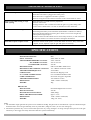
SPECIFICATIONS
CONTROL BOX
PROTECTION RATING:
INPUT VOLTAGE:
TRANSFORMER PRIMARY VOLTAGE:
SECONDARY VOLTAGE:
CONTROLLER VOLTAGE:
RECEIVER TYPE:
RECEIVER CODE STORAGE CAPACITY:
TRANSMITTER FREQUENCY:
CODING TYPE:
No. of CODE COMBINATIONS:
CODE GENERATION:
TRANSMITTER BATTERY:
DIMENSIONS:
WEIGHT:
IP56
230V- 240V AC 50Hz
230V / 240VAC
24V AC 100 VA
24V DC
UHF 433.92 MHz. AM Receiver
30 x 4 Button Transmitter Codes
433.92 MHz
SecuraCode® Hopping Code
Over 4.29 Billion Random Codes
Non-linear Encryption Algorithm
A23 Alkaline 12 Volts
190W x 240H x 100D (mm)
4Kg
DRIVE UNIT
MOTOR TYPE:
MOTOR VOLTAGE:
MAXIMUM PULLING FORCE:
DRIVE ARM ROTATION SPEED:
DIMENSIONS:
WEIGHT:
Permanent Magnet Direct Current
24V DC
200N (20Kg)
approx. 8°/sec
135W x 290H x 230D (mm)
13Kg (incl. arms)
Note:
1. The maximum weight gate that the opener can be installed on 250Kg. The gate must be well balanced. A person of limited strength
should be able to move the gate manually with very little effort (15Kg force max.) in case of an emergency.
2. Intermittent operations may occur in areas which experience very strong wind gusts. A strong wind puts extra pressure on the gate
which may in turn trigger the safety obstruction detection system intermittently.
20
PARTS LIST
WHEN ORDERING SPARE PARTS PLEASE
QUOTE THE ORDER CODE NUMBER
TO YOUR YOUR INSTALLER/DEALER
21
WARRANTY AND EXCLUSION OF LIABILITY
1. This warranty is an addition to any non-excludable conditions or warranties that are implied into this contract by relevant statute,
including the Trade Practices Act 1974 (Cth).
2. Subject to all of the matters set out below, Automatic Technology Australia Pty Ltd ("ATA") warrants:
(a) swing and sliding gate opener drive units for twelve (12) months or 2500 cycles, whichever occurs first;
(b) roll-up and overhead door opener drive units for twenty four (24) months or 5000 cycles, whichever occurs first; and
(c) all components and accessories for twelve (12) months,
from the date of purchase (specified in the sales docket receipt) as free of any defects in material and workmanship.
3. This warranty applies only where the purchaser:
(a) immediately notifies ATA or the retailer of the alleged defect;
(b) returns the product to the retailer; and
(c) presents the relevant sales docket and this warranty document to the retailer to confirm the date of purchase.
4. Except for this warranty, ATA gives no warranties of any kind whatsoever (whether express or implied), in relation to the product,
and all warranties of whatsoever kind relating to the product are, to the extent permissible by statute, hereby excluded.
5. To the extent permissible by statute, ATA disclaims any liability of whatsoever nature in respect of any claim or demand for loss
or damage which arises out of:
a) accidental damage to or normal wear and tear to the product or to the product's components;
b) any cost relating to damage resulting from wear and tear;
c) blown fuses, loss or damage caused by electrical surges, power surges or power spikes;
d) loss or damage due to theft, fire, flood, rain, water, lightning, storms or any other acts of God;
e) maximum continuous operating time exceeding one (1) minute in ten (10);
f) maximum operating force exceeding 15Kg (150N) when moving the door or gate manually to the open or closed position;
g) door surface area and/or weight exceeding 15m2 and 100Kg respectively;
h) residential gate weight exceeding 400Kg;
i) door or gate not in safe and correct working order and condition;
j) evidence of unauthorised repairs;
k) any cost relating to damage caused by misuse, negligence or failure to maintain the equipment in a proper working
order as per clauses (d) through (i);
l) installation, adjustment or use which is not in accordance with the instructions set out in installation instruction manual;
m) attempted or complete modification or repairs to the product carried out by a person who is not authorised or has not been
trained by ATA to carry out such modification or repairs;
n) faulty or unsuitable wiring of structure to which the product is fixed or connected;
o) radio (including citizen band transmission) or any electrical interference;
p) damage caused by insects;
q) loss or damage to any property whatsoever or any loss or expense whatsoever resulting or arising there from or any
consequential loss;
r) any cost or expense arising due to manufacturer recall of any product;
s) any cost or expense due to negligence of the approved service provider;
t) installation of a residential garage door or gate opener in a commercial or industrial situation or a non-single
residential dwelling.
6.
7.
8.
9.
10.
11.
12.
13.
ATA's liability under this warranty is limited, at ATA's absolute option, to replacing or repairing the product which ATA, in its
unfettered opinion, considers to be defective either in material and/or workmanship or to credit the dealer with the price at which
the product was purchased by the dealer.
This warranty does not extend to cover labour for installation.
This warranty is limited to Return-to-Base (RTB) repair and does not cover labour for on-site attendance.
This warranty is void if the Product is not returned to the manufacturer in original or suitably secure packaging.
This warranty is only applicable for repairs to the product carried out within Australia.
This warranty does not cover consumable items including globes, batteries and fuses.
This warranty is not transferable.
Where the Product is retailed by any person other than ATA, except for the warranty set out above, such person has no authority
from ATA to give any warranty or guarantee on ATA's behalf in addition to the warranty set out above.
Notes:
1. One (1) cycle = one (1) open and one (1) close action of the door or gate.
2. This warranty is to be read in conjunction with the owner's copy of the installation instruction manual.
22
NOTES
Purchased From ___________________________________ Phone ______________________
Installed By _______________________________________ Date _______________________
Serial No. ________________________________________
23
AUTOMATIC TECHNOLOGY AUSTRALIA PTY LTD
ABN 11 007 125 368
17-19 Advantage Rd, Highett, Victoria, Australia 3190
Tel: +61 3 9532 2788 Fax: +61 3 9532 2799
Web: www.ata-aust.com.au Email: [email protected]
© May 2005 Automatic Technology Australia Pty Ltd. All rights reserved. SecuraCode® is a registered trademark of Automatic Technology Australia Pty Ltd.
In an ongoing commitment to product quality ATA reserve the right to change specification without notice. E&OE.
Printed For Export.