1
Leica DNA03/DNA10
User Manual
Version 2.0
English
2
Digital Level
Product ID
Congratulations on your purchase of the new
Leica Geosystems digital level.
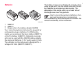
This manual contains important
safety directions as well as
instructions for setting up the
product and operating it. Refer to "Safety directions"
for further information.
The type and the serial-no. of your instrument are
written on the label located on the underside of the
instrument. Enter the type and serial number in your
manual and always refer to this information when
you need to contact your agency or Leica Geosystems authorized service workshop.
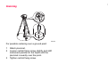
Please read these instructions carefully before putting the instrument into operation.
Trademarks
• Windows and Windows CE are a registered
trademark of Microsoft Corporation
•
CompactFlash and CF are trademarks of
SanDisk Corporation
All other trademarks are the property of their respective owners.
Type:_____________ Serial-no.:______________
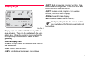
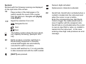
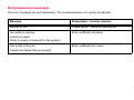
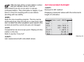
Symbols used
DANGER
Immediate hazards of use that lead to
personal injuries or even death.
WARNING
Hazards of use or inappropriate application that lead to personal injuries or even
death.
CAUTION
Hazards of use or inappropriate application that lead to minor personal injuries
but appreciatble material, financial or
enviromental damage.
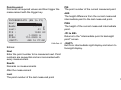
Useful information for the operator to use
the instrument properly and efficiently.
3
4
Contents
Introduction ......................................... 8
Centering........................................................ 30
Principal of measurement .......................... 9
Validity........................................................ 9
Measuring ..........................................31
Special features................................. 10
Most important elements.......................... 11
Measurement values................................ 14
Applications.............................................. 15
Line levelling .................................................. 15
Area levelling.................................................. 17
Computer software package
Leica Geo Office (LGO) ........................... 18
PCMCIA or CF card ................................. 20
Equipment ................................................ 21
Unpack ........................................................... 21
Batteries ......................................................... 22
Batteries ......................................................... 23
Memory card .................................................. 24
External power supply.................................... 25
Measurement preparations .............. 26
Levelling up .................................................... 27
Focussing the telescope ................................ 29
General notices ........................................31
Height reading ..........................................31
Distance measurement.............................32
Angle measurement .................................33
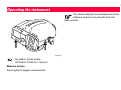
Operating the instrument..................34
Keyboard and display ...............................35
Fixed keys ...................................................... 36
Key combinations........................................... 36
Navigation keys.............................................. 37
Entry keys ...................................................... 38
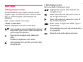
Display keys .............................................39
Navigating the menus .................................... 41
Illumination menu ........................................... 41
User input .................................................42
Entering numeric values................................. 42
Entering alphanumeric values........................ 43
Inserting letters and numbers......................... 43
Deleting letters and numbers ......................... 44
Set of charaters.............................................. 44
Find point ................................................. 45
Start programs...................................72
Wildcard-search ............................................. 48
Set job ............................................................ 73
Set line ........................................................... 74
Set tolerances ................................................ 76
Select method ................................................ 78
Check list........................................................ 78
Start programs error messages ..................... 79
Technical hints for measurements .. 49
Special measuring situations ................... 49
Important instrument settings......................... 50
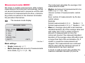
Measurement modes (MODE) ....................... 51
Measuring progress ....................................... 53
Repeating a measured sight .......................... 54
Managing point IDs ........................................ 55
Data and memory management............... 56
Measure & Record............................. 57
Starting display (1st backsight) .................... 59
Foresight display ............................................ 60
Backsight display ........................................... 61
Switching to intermediate sight or set
out sight.......................................................... 61
Surveying intemediate points ......................... 62
Set out............................................................ 64
Functions (FNC) ................................ 67
Test measurement ......................................... 68
View measurement ........................................ 68
Code............................................................... 69
Point ID and increment................................... 70
Manual entry of measured values .................. 70
Measurement programs....................80
Introduction...............................................80
Line levelling.............................................81
Typical measurement display of
Line points (B/ F)............................................ 82
Last measurement backsight ......................... 83
Last measurement foresight........................... 84
Intermediate sight and set out........................ 84
Station results ................................................ 85
Exceeding tolerances..................................... 86
Line cut .....................................................87
Line Adjustment........................................89
Data-Management ......................................... 92
Check & Adjust .........................................93
"A x Bx" method ........................................... 95
"A x x B" method ............................................ 97
Measuring procedure ..................................... 99
5
Coding .............................................. 101
Entering a code ...................................... 102
Quick Code ............................................ 103
Memory information................................121
Data export .............................................122
Data import ............................................124
Menu settings .................................. 105 Data storage.....................................126
System information ................................ 111
Start programs ............................................. 126
Measurement program................................. 127
Measurement mode and corrective
parameter..................................................... 128
Coding.......................................................... 129
Fix points coordinates .................................. 129
RS232 interface ........................................... 130
Check with collimator ................................... 112
Safety Directions .............................131
Data manager................................... 114
Intended use of instrument .....................131
All settings.............................................. 107
System ......................................................... 107
Measuring .................................................... 108
Communication ............................................ 109
Unit selection................................................ 110
Date and time............................................... 111
Card functions ........................................ 115
View /edit data........................................ 116
Measurements ............................................. 116
Fix points...................................................... 118
Code list ....................................................... 119
Delete memory............................................. 120
Adverse uses ............................................... 132
Limits of use ...........................................132
Responsibilities.......................................133
Hazards of use ............................................. 134
Electromagnetic Compatibility (EMC).....137
FCC Statement, applicable in U.S. .............. 139
Product labelling........................................... 140
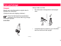
Care and storage .............................141
Transport...................................................... 141
6
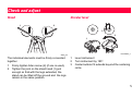
Check and adjust............................. 145
Stand............................................................ 145
Circular level ................................................ 145
Reticle .......................................................... 146
Technical data ................................. 147
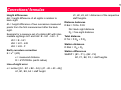
Corrections/ formulas ..................... 150
Accessories ..................................... 151
Sensor-error messages .................. 152
Index ................................................. 153
7
8
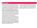
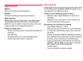
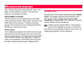
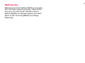
Introduction
With the acquisition of this Leica digital level you
have chosen a product of excellence, with state of
the art ergonomy and outstanding measuring accuracy. Both types of the instrument feature electronic
reading of the measuring staff height. The bull's eye
bubble only has to be roughly set for every stationing. The fine adjustment of the target beam is
done automatically by the high-precision compensator. A key press triggers the electronic measurement. Should it not be possoble for once, to make
an electronic measurement, then the height can be
optically read from a conventional, metered staff
and manually enterred with the keypad.
Leica digital levels come with a wide range of software functions. Single height measurements are
easy to make and also just as easy is measuring all
the elements in a line levelling job. With the program "Line Adjustment", measured heights can be
compared directly with the height of fixed points and
adjusted to them if desired. Staking out absolute
heights or height differences or point-to-point measurements are all easily possible.
The unique concept of format files enables the output of store data in almost any format. The format
files can be created individually and modified asy
desired. The logfile e.g., can be completed in the
field and transferred to an internal memory card.
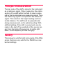
Principal of measurement
The bar code of the staff is stored in the instrument
as a reference signal. When measuring, the visible
section of the staff within the field of view is captured by the line decoder as a measuring signal. Then
the measuring signal is compared to the reference
signal. This results in the height reading and horizontal distance. The staff must be perpendicular
during measurement, as for optical levelling. With
artificial lighting of the staff, mesurements can be
made in the dark (The sensitivity of the sensor ranges from the highest frequiencies of visible light
down to the frequency of infra red light).
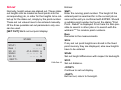
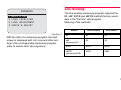
Validity
This manual is valid for both instruments of the DNA
series. Sections only valid for the DNA03 are marked accordingly.
9
10
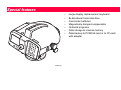
Special features
•
•
•
•
•
•
•
DNA03_01
Large display, alphanumeric keyboard
Bi-directional horizontal drive
Camcorder batteries
Magnetically damped compensator
Onboard programs
Data storage to internal memory
Data backup to PCMCIA-card or to CF-card
with adapter
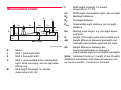
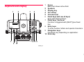
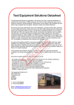
Most important elements
8
11
14
12 13
7
6
5
19
4
3
2
1
9
15 16 17
10
18
20
21 22 23 24
DNA03_02
1
2
3
4
5
6
7
8
9
10
11
12
13
14
15
16
17
18
19
20
21
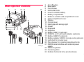
On/ off button
Base plate
Foot screws
Horizontal circle
Lever to unlatch battery
Battery compartment
Button to unlatch card compartment cover
Card compartment cover
Display
Circular level
Hand grip with aiming sight
Ocular
Keyboard
Objective
Battery GEB111 (optional)
PCMCIA or CF-card with adapter (optional)
Battery GEB121 (optional)
Battery adapter GAD39; 6 single cells (optional)
Light duct for circular level
Plug stopper for crosshair adjustment knob
RS232 serial interface with external power
supply
22 Measuring button
23 Focussing drive
24 Endless horizontal drive (bi-directional)
11
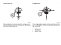
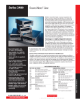
Vertical axis tilt
12
Compensator
3
1
2
2
DNA03_05
After centering the circular level the instrument is
almost horizonal. A minimal instrument tilt remains,
this is the vertical axis tilt.
DNA03_06
The compensator corrects for the vertical axis tilt on
the line-of-sight so that the instruments aim is exactly horizontal.
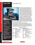
1
2
3
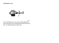
Vertical axis
Plumb line
Line-of-sight
Collimation error
α
DNA03_07
The Collimation error (α) is the vertical angle between the actual line-of-sight and the ideal horizontal
line. It is determined by a level test.
13
F
Measurement values
C1
2
C2
1
DB
S
DF
Dint
Dint
Z
F
B
HCol
dH
int
dh
H
H
Ho
H=0.0000m
DNA_Messgrössen
Staff height foresight. for double
observations: F1, F2
int
Staff height intermediate sight / set out sight
DB
Backsight-distance
DF
Foresight-distance
DInt
Intermediate sight distance/ set out sight
distance
Ho
Starting point height, e.g. as height above
sea level
H
Height of foresight point/ intermediate point
dH
Height difference between backsight and
foresight/ intermediate sight/ set out sight
dh
Height difference between two
measurements taken in sequence
(intermediate sight/ set out sights/ foresight)
Instrument horizon (= height of line-of-sight)
S
Station
1
Staff 1 (backsight staff)
2
Staff 2 (foresight staff)
HCol
C
Staff C (intermediate point: intermediate
sight while surveying, set out sight while
setting out)
Additional calculations with these dimensions can
be found in section, Corrections/ formulas.
B
Staff height backsight. for double
observations: B1, B2
14
Applications
DNA10
Mainly for technical levelling tasks.
DNA03
Technical levelling and precision levelling.
Staff selection
Measuring accuracy depends on the staff used in
combination with the instrument. Use standard
staffs for low to medium range accuracy and invar
levelling staffs for the highest precision.
Range of application
• Simple measurements using staff and distance
readings
• Line levelling
• Sureying and set out intermediate points.
• Online operations with a computer.
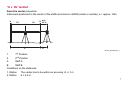
Line levelling
Dependent on the required accuracy the same rules
for levellling and regulations within the given countries apply as for optical levelling.
Adhere to the following general rules:
• Maintain same target distance for back and
foresight.
• Measure a fore and back run and check it by
the error after the closing point.
Exclusively for precision levelling:
• Limit target distance, < 30m.
• Minimum ground clearance of >0.5m required
to minimize refractionary influences of ground
proximity.
• Double observance (BFFB, aBFFB) to increase
the reliability of the measurement and to reduce
possible errors caused by the staff sinking.
• Applying alternating observations procedures
(aBFFB = BFFB FBBF) to eliminate horizontal
tilt (residual error of the automatic
compensator).
• Use an umbrella in strong sunlight.
15
•
Precision Mode: "Precise" is activated in the
tolerance-settings for line levelling, the
instrument monitors the distance of the height
reading (Ziellinie) to both ends of staff, top and
bottom. The reduced number of staff code
elements may slightly lower the measuring
accuracy of measurements taken on the edge
of the staff. If the distance is less than 50cm a
warning is displayed. When this mode is
activated, the top and bottom limits of the staff
are automatically converted to a 3m Invar staff.
In order to use different staff sizes, the limit
values can be manuallly adjusted. The
precision mode also monitors measuring
distances critical to the staff. These distances
depend on the physical properties of the
instrument and of the staff. The measuring
accuracy of height measurements within these
distance ranges may also be slightly lower. A
warning is displayed if the measuring distance
is within the following ranges: 13.250m 13.500m and 26.650m - 26.900m. The
Precision Mode is meant as a helpful tool to
increase measuring accuracy. Activating
Precision Mode for line levelling with typical
accuracy is possible hut not necessary.
16
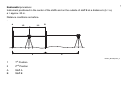
Area levelling
Unlike line levelling, the individual target distances
in area levelling may be very different. Depending
on the required accuracy, a possible line-of-sight
error or the influence of the earth’s curvature may
have be taken into consideration.
In strong sunlight and when working for
long periods, cover instrument and stand
with an umbrella.
17
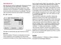
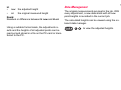
Computer software package
Leica Geo Office (LGO)
The Leica Geo Office (LGO) software package
includes a number of programs and tools that support working with the instrument. LGO-Tools is a
part of the complete LGO package and can be
installed from the supplied CD.
After the tools have been successfully installed, the
following program modules are available:
•
Data Exchange Manager
Data exchange of fixed points, measurements,
code lists and data output formats between the
instrument (internal memory) and the computer.
Data exchange between PCMCIA-card (in the
instrument) and the computer.
•
Coordinate Editor
Import/ export/ create/ edit coordinate data.
•
Codelist Manager
Creates and edits code lists.
•
Software Upload
Uploads system software and measuring
programs.
•
Format Manager
Creates and edits user defined output formats.
•
Configuration Manager
Creates and edits user defined instrument
settings.
•
DNA GSI Converter
Converts DNA03/ DNA10-data in the new GSIformat into data in the old GSI-format of the
NA3003/ NA2002.
For more information on the Leica Geo
Office refer to the detailed Online-help.
LEICA Geo Office (LGO) is available as a separate
software package and includes the basic module as
well as the LGO Tools package. The base module
and the corresponding options offered supportvisualization, calculation, quality testing and recording of measurement data of various Leica
instruments.
18
The following options are available for the evaluation of levelling data:
•
Display, editing and evaluation of single line
levelling
• Creating and adjusting1D height grids.
Further information on the LGO will gladly be given
by your local Leica representative.
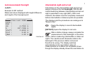
Data flow:
We recommend using the XML-format to transfer
measurement data from the DNA to the LGO and its
modules. The required Format file (DnaXml.frt) is
located on the supplied CD and can be installed on
the instrument with the "Data Exchange Manager".
The transfer of job data from the instrument
to the computer is then also done through
the "Data Exchange Manager".
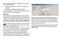
As LGO / LevelPak-Pro read in *.lev files by default,
we recommend giving the file to be transferred to
the computer a *.lev name. The following input
mask is displayed in the LGO Data Exchange
Manager when transferring data to the computer. As
an example, the format file DNAXml5 was selected.
We advise against transferring measured data in
GSI format from the level to the LGO software pakkage. As the GSI format does not include all information, errors may occur during height calculations
and lead to wrong results.
Transferring measurement data from the level test
from the DNA to LGO is also not recommrnded in
XML format.
19
20
PCMCIA or CF card
Measured data is stored in the internal memory of
the DNA03/ DNA10 and remains there. In addition,
data can be backed up to a PCMCIA or CF card
from the internal memory.
The system supports the PCMCIA standard for
ATA-Flash, SRAM or CF memory cards. Data
exchange with the computer is done via an internal
PCMCIA- drive or with the external OMNI-drive offered by Leica Geosystems.
Files can also be exchanged between the memory
card in the instrument and the computer via the RS
232 serial interface using the Leica Survey Office
software.
Due to possible incompatibility with internal
drives, data exchange with SRAM-cards is
best done with the external OMNI-drive.
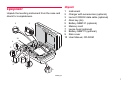
Unpack
Equipment
Unpack the levelling instrument from the case and
check for completeness.
2
3
10
1
2
3
4
5
6
7
8
9
10
Instrument
Charger with accessories (optional)
Lemo-0/ RS232 data cable (optional)
Allen key (2x)
Battery GEB121 (optional)
Memory card
Lense hood (optional)
Battery GEB111 (optional)
Rain cover
User Manual, CD-ROM
4
5
1
6
7
8
9
DNA03_03
21
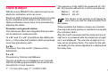
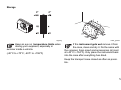
Batteries
1
The battery charge is not displayed correctly when
using single cells. Use the single cells with the battery adapter as emergency power supply. The
advantage of the single cells is in a lower rate of
discharge even over long periods.
2
Use the Leica Geosystems batteries, chargers and accessories or accessories
recommended by Leica Geosystems to ensure the
correct functionality of the instrument.
3
DNA_GEB
1 GEB121
2 GEB111
3 Single cells in the battery adapter GAD39
Your Leica Geosystems instrument is powered by
rechargeable plug-in batteries. For DNA instruments, we recommend the basic battery (GEB111)
or the Pro battery (GEB121). Optionally six single
cells can be used with the GAD39 battery adapter.
Six single cell batteries (1.5 V each) supply 9 Volts.
The voltmeter on the instrument is designed for a
voltage of 6 Volts (GEB111/ GEB121).
22
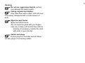
Batteries
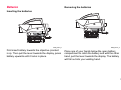
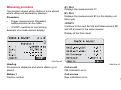
Removing the batteries
Inserting the batteries
a
DNA_BTTR_1
First insert battery towards the objective (contact
in a). Then pull the lever towards the display, press
battery upwards until it locks in place.
DNA_BTTR_2
Place one of your hands below the open battery
compartment to catch the battery and with the other
hand, pull the lever towards the display. The battery
will fall out into your waiting hand.
23
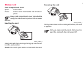
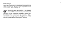
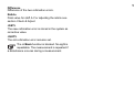
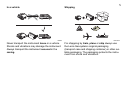
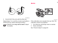
Memory card
24
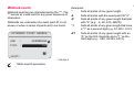
Removing the card
Card compartment cover
Open:
Press latch.
Close:
Press cover downwards until it locks in
place.
Keep card compartment cover closed while
using the instrument to protect it from water
and dirt.
Inserting the card
DNA03_PCMCIA_2
Firmly press down on the card eject button; the card
is ejected.
Only use clean and dry cards. Only insert or
eject the card with the instrument off.
DNA03_PCMCIA_1
Insert card with the Leica logo facing up until it locks
in at the end position.
Check: the card's eject button is flush with the card.
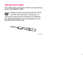
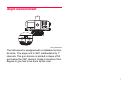
External power supply
The cable used must have a ferrite core (electromagnetic compatibility, EMV).
Always plug the Lemo-plug with the ferrite
core into the instrument. Only plug in or
remove the plug when the instrument is switched
off. Cables delivered by Leica Geosystems come
standard with a ferrite core.
Ferrit_01
25
26
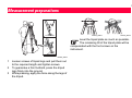
Measurement preparations
DNA03_Stativ2
DNA03_Stativ3
Level the tripod plate as much as possible.
The remaining tilt of the tripod plate will be
compensated with the foot screws on the
instrument.
DNA03_Stativ1
1
2
3
Loosen screws of tripod legs and pull them out
to the required length and tighten screws.
To guarantee a firm foothold, press the tripod
legs firmly into the ground.
While pressing, apply the force along the legs of
the tripod.
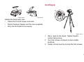
Levelling up
2
1
DNA03_Stativ4
NA03_Stativ5
Handle the tripod with care:
•
•
•
Check the fit of all screws and bolts.
During transport always use the cover supplied.
Only use the tripod for surveying.
DNA03_Horiz_1
1
2
3
Place level on the tripod. Tighten tripod's
central fixing screw.
Turn foot screws of tribach to their middle
positions.
Center circular level by turning the foot screws.
27
28
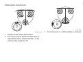
Centering the circular level
A
B
C
NA03_Horiz_3
DDNA03_Horiz_2
1
2
Position ocular above foot screw C.
Turn foot screws A and B simultaneously in
opposite directions until the bubble is in the
center (of the imaginary "T").
3
Turn foot screw C until the bubble is centered.
Focussing the telescope
NDNA03_Monok_fok_l
NDNA03_Monok_fok_l
1
2
Point telescope towards bright background (e.g.
white paper).
Turn ocular until reticle is focussed and appears
sharp and black.
3
4
Aim telescope on staff using the coarse aiming
device.
Turn focussing knob until image of staff is
sharp. Moving the eye up and down behind the
ocular should not show the staff and reticle be
displaced against one another.
29
30
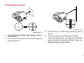
Centering
Zentrier
For possible centering over a ground point:
1
2
3
Attach plummet.
Loosen central fixing screw slightly and shift
instrument parallel on the tripod until the
plummet is exactly over the point.
Tighten central fixing screw.
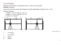
Measuring
General notices
Height reading
•
Example of an optical rmeasurement:
•
•
First check and adjust the line-of-sight errors,
then the circular level on the instrument and
then the staff.
• Before starting work in the field
• After long storage periods
• After long transportation
Keep the optics clean. Dirt or condensation on
the optics can limit measurements.
Before starting work, let the instrument adjust to
the ambient temperature (approx. 2 minutes per
°C of temperature difference).
d
H
DNA_03_Höh_ables
1
2
3
Set up instrument, level it and focus the reticle.
Set up staff verically.
Coarsly aim at staff.
31
32
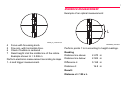
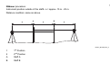
Distance measurement
Example of an optical measurement:
27
27
26
26
25
25
DDNA_03_LatteF-Kreuz
4
5
6
7
Focus with focussing knob.
Fine aim with horizontal drive.
Check if bubble is centered .
Read height H at the middle line of the reticle.
Example shown: H = 2.586 m
Perform electronic measurement according to steps
1...6 and trigger measurement.
NDNADNA_Dist-Mess
Perform points 1 to 6 according to height readings.
Reading
Distance line above:
2.670 m
Distance line below:
2.502 m
Difference L:
0.168 m
Distance d:
Result:
Distance d = 100 x L
16.8 m
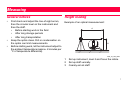
Angle measurement
DNA_Winkel-Mess
The instrument is equipped with a rotatable horizontal circle. The angle unit is 360° subdivided into 1°
intervals. The gon division is printed in steps of 50
gon below the 360° division. Angle conversion from
degree to gon has to be done by the user.
33
34
Operating the instrument
The shown displays are examples and local
software versions may deviate from the
base version.
DNA03_03
On switch: Press briefly
Off switch: Press for 1 second
Measure button
Press lightly to trigger measurement.
1
Focus
Black bar shows active field.
2 Symbols
3 Display key
4 On/ off key
5 Circular level
6 Fixed keys (left row of keys)
Keys with fixed functions.
7 Fixed keys 2nd level
Function is triggered with [SHIFT] plus fixed
key.
8 Entry keys
To enter number, letters and special characters.
9 Navigation keys
Functions vary depending on application.
10 Enter-key
Keyboard and display
1
2
7
8
SET
EC
T
<ENDE>
3
6 9 10
4
5
DNA03_04
35
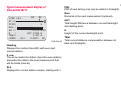
Fixed keys
Switching to point-to-point measurement.
Key combinations
SET OUT
Set measurement mode.
Key with any function from the FNC-menu.
Switch to setout.
Measurement programs, main menu.
INV
Data manager.
Quit measurment program, function or edit
mode step-by-step, retrieving the old
parameters. Cancel /stop measurement.
Invert staff (0-mark at the top) for measurement.
The "T" symbol appears as long as INV is active.
Revert with a renewed press on INV.
Switching to the 2nd key level (SET OUT,
INV, FNC, MENU, Lighting, PgUp, PgDn,
<<Back, INS) and toggling numeric/
alphanumeric.
Measured values with inverted staffs are negative.
Delete character/ field, Cancel/ stop
measurement.
FNC
Functions that support the measurements.
MENU
Confirm entry, continue to next field.
Instrument settings, system-Information, line-ofsight check with collimator (DNA03 only).
Display and circular level lighting.
36
PgUp
Navigation keys
"Page Up"= scroll up to previous "page" if display
contains multiple pages.
The navigation keys take on different functions,
depending on the mode in which they are used:
PgDn
•
•
•
•
"Page Down" = scroll down to next "page" if display
contains multiple pages.
Focus control
Cursor control
Navigate through the selection
Select resp. confirming parameters
<<Back
Return to last sight, e.g. return to backsight and
repeat.
37
Entry keys
...
Enter numbers, letters and special
characters.
Enter decimal point and special characters.
Toggle positive/ negative signs; enter
special characters.
In alphanumeric mode:
• Quick consecutive presses call up the next sign
(letter/ special character, number).
• After a pause of approx. 0,5 seconds, the
presently displayed sign is accepted and the
cursor jumps to the next position.
The exact function is explained in detail in
the appropriate sections of the manual.
38
<QUIT> Ends measuring program/ function. Parameters entered are ignored. In MENU, PROG and
DATA returns to selection menu.
Display keys
<QUIT> Leaves a sub program or an auxillary
function; returns to initial display.
BF
BF
LINE LEV
ST.2
BACK
PtID:
1 EC
Rem :
-----dH T:
0.5358 m
H
:
114.7918 m
TBal:
1.80 m
<QUIT> <CL> <LAST> QC
<PREV> Reverts to last display.
<REC> Stores data to internal memory.
All displays depicted in the manual contain
only text without the following explanation of
the symbols.
DNA-Dde 1
Display keys are additional "software keys" for a
given situation. They can be marked with the navigation keys. When the cursor is over a button, the
corresponding function can be called up with
[ENTER].
General display keys:
<CONT> Accept values or conditions and move to
the next screen.
<OK> Confirm and continue.
<SET> Set displayed parameter and continue.
39
Symbols
Symbols with the following meaning are displayed
on the right side of the screen:
1/3
Page number of the total pages or for
search results the count of the counter
from the total sum. Navigate with [PgUp]
resp.[PgDn].
Signal the selection from a list.
Navigate the list.
Quit.
Quit.
The battery symbol shows the level of battery capacity remaining. (Example: 50%
full).
EC
T
Earth curvature correction switched on.
Electronically measured or manually
entered staff heights are automatically
corrected for earth's curvature.
Inverse staff switched on. It is only possible
to take measurement with the staff inverted.
[SHIFT] was pressed.
N
Numeric digits activated.
α
Alphanumeric characters activated.
QC
QuickCode. QuickCode is activated when a
codelist is loaded into the instrument and
when the cursor is over a button.
Enter the corresponding two digit QuickCode to trigger the measurement and to
save it together with the assigned code.
QuickCode is not activated when the cursor
is over an input field or when no codelist is
loaded into the instrument. In this case
entering a two digit code produces an error
message.
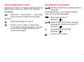
40
Illumination menu
Navigating the menus
Switch on illumination, displays setting
options.
Example: Function menu [FNC]
ILLUMINATION
FUNCTIONS
1 TEST MEASUREMENT
2 VIEW MEASUREMENT
3 CODE
4 PtID & INCREMENT
5 MANUAL INPUT
<QUIT>
1
2
3
4
All Off
Displ+CircL: economic
Displ+CircL: permanent
Circ.Level only
<QUIT>
DNA-Dde 2
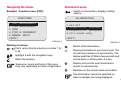
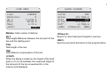
Starting a function
... Call it up by directly entering a number 1 to
5, or
DNA-Dde 3
Switch off all illumination.
Starts the function.
Display illumination in economic mode. The
circular level remains on permanently. The
display switches off after a few seconds and
comes back on at the press of a key.
Sequence, layout and texts of the menu
may vary depending on local configuration.
Display and circular level illuminations
remain on permanently.
highlight it with the navigation keys.
Switches on the circular level illumination.
The illumination cannot be switched on
when messages are being displayed.
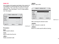
41
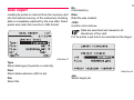
User input
Entering numeric values
Numeric fields can only contain numeric values,
negative signs and decimal points. Numeric fields
are e.g.: starting heights, staff readings and
distances.
2. Edit displayed value
Edit a few digits of displayed value:
Highlight the desired entry field with the
navigation keys.
Starts edit mode and places the cursor at
the far right of the field.
Enter numeric values in two ways:
Starts edit mode and places the cursor at
the far left of the field.
1. Enter a new value
Replace displayed value with a new value:
Place cursor on digit to be edited. Type in
desired digit.
Use navigation keys to highlight the desired
entry field. Type numeric value and decimal
point using the keyboard.
Sign can be changed while making the
entry.
Positive to negative or vice-versa.
Acknowledge entry and the next entry field
is highlighted.
Acknowledge entry and the next entry field
is highlighted.
Discards entry and restores old value.
42
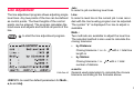
Entering alphanumeric values
Alphanumeric fields can contain numeric as well as
alphanumeric values e.g.: PtID, Code, Attribute.
Procedure:
Switch into - entry mode. In - entry mode
a key is used for 3 letters and one digit.
Example:
Entering the letters S, T and U.
Press S: once, T: twice, U: three times,
1: four times. If the desired letter or number
is missed just continue pressing until it
comes around again.
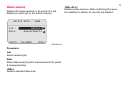
Inserting letters and numbers
Inserting a digit into an existing number in
edit mode.
A missing digit (e.g. -15 is entered instead of
-125) can be inserted afterwards.
Place cursor on the "1"
(example.: 1 5)
Inserts a digit (0 in numeric, space in
alphanumeric fields) to the right of "1"
(example: 1 0 5 ).
key inserts the desired digit
(example: 1 2 5)
Confirm entry/ change.
43
Deleting letters and numbers
Deleting single characters:
Deleting single characters in edit mode.
Example:
1 AB C 3 2
44
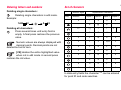
Set of charaters
A B32
Deleting all characters:
Press several times until entry field is
empty. A final press restores the previous
value.
Numeric values are always displayed with
decimal points. Decimal points are not
deleted but set to zero.
[CE] deletes the entire highlighted value
when not in edit mode. A second press
restores the old value.
Numeric digits
Key
Numeric
Alphanumeric characters
Alpha 1
Alpha 2
Alpha 3
Alpha 4
0
/
$
%
0
.
#
@
&
.
+/-
(*)
?
!
1
S
T
U
1
2
V
W
X
2
3
Y
Z
Space
3
+
-
4
J
K
L
4
5
M
N
O
5
6
P
Q
R
6
7
A
B
C
7
8
D
E
F
8
9
G
H
I
9
In data entry fields the character "*" can be entered
for point ID and code searches.
Signs
In the alphanumeric set of charaters, the "+"
and "-" signs are treated like normal
alphanumeric characters. They have no
mathematical function.
Special characters
*
WILDCARD for point searches only (see
"Wildcard-Search").
In edit mode the position of the decimal
point cannot be changed.
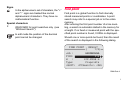
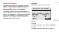
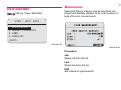
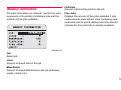
Find point
Find point is a global function to find internally
stored measured points or coordinates. A point
search may refer to a special job or to the entire
memory.
After entering the first point number of a line levelling, a search is automatic started in the memory for
a height. If no fixed or measured point with the specified point number is found, 0.000m is displayed.
Should one or more points be found, then the result
of the search is displayed in the following dialog.
FIND POINT - RESULT
(
1/3)
Job :
PtID:
H
:
Type:
<QUIT>
HEERBRUGG
P13
412.2259 m
Fixpoints
<PtSearch+> <OK>
DNA-Dde 4
45
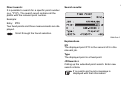
Direct search:
It is possible to search for a specific point number
(e.g. "P13"). The search result contains all the
points with the relevant point number.
46
Search results:
Example:
Entry: P13
Two fixed points and three measurements are displayed.
Scroll through the found selection.
DNA-Dde 5
Explanations
2/5
The displayed point P13 is the second of 5 in the
relevant job.
Type
The displayed point is a fixed point.
<PtSearch+>
Calling up the extended point search. Enter new
search criteria.
If no points are found a message is
displayed with that information.
The Search function always finds fixed point (in
Fixed Points-jobs) before measured point (in Meas.
Jobs) that fulfill the search criterion. If several points
are found that fulfill the search criterion, they are
listed chronologically. The instrument lists the oldest
fixed point first
The entered point number is searched for in the
memeory after confirming it with ENTER. The
search result is displayed in the dislog "Point
Search - Search Results" and includes all points
with corresponding point numbers.
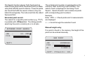
Extended point search:
Enter : P13 --> 2 fixed points and 2 measurements
are displayed.
The search for a specific point number (e.g. "P13")
is possible with <PtSearch+>. The dialog permits
searching the point a random job or in all jobs.
EXTENDED POINT SEARCH
JOB
:
PtID. :
ALL JOBS
P13
Example:
<-- --> Scroll through the selection found
Manual height entry
If no point is found in the memory, the height of the
point can be entered manually.
NEW POINT
<QUIT>
JOB
:
PtID. :
H0
:
HEERBRUGG
P113
0.0000 m
<QUIT> <PtSearch+> <OK>
47
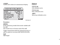
Wildcard-search
Examples:
Wildcard-searches are characterized by the "*". The
"*" serves as a wild-card for any given sequence of
characters.
*
finds all points of any given length.
A
finds all points with the exact point ID "A".
A*
finds all points of any given length that start
with "A" (e.g.: A, A9, A15, ABCD).
*1
finds all points of any given length that have
a "1" as a second digit (e.g. A1, B12, A1C).
A*1
finds all points of any given length with an
"A" as the first character and a "1" as the
third digit (e.g.: AB1, AA100, AS15).
Wildcards are used when the exact point ID is not
known or when a series of points are to be found.
EXTENDED POINT SEARCH
JOB
:
PtID. :
HEERBRUGG
13*
ż
<QUIT>
DNA-Dde 6
Starts search procedure.
48
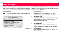
Technical hints for measurements
Special measuring situations
Vibrations
Vibrations at the instrument, e.g. due to wind can be
damped by touching the upper third of the tripod.
Back light
Use the lense hood (optional accessory) to cover
the objective when back light disturbs your work. As
a last resort, use your hands to shield the objective
from disturbing backlight.
Darkness
Evenly illuminate the measuring area of the staff
with a flashlight or spotlight in darkness.
Measuring at the beginning of the staff
Measurements slightly below the zero point are
possible (negative measured values).
Measuring at the upper end of the staff
With the following staffs, measurements can be
made up to the end of the staff: 4.05m; 2.95m;
2.70m; 1.95m und 1.82m.
With other staff lenghts, measurements up to the
upper ends are not possible.
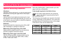
Code length required in the field of view
For exact measurements, the centering
area in the field of view should be free of
any interfering cover.
The following code lengths are required in the field
of view, depending on the distance, from which the
permitted amount of interfering cover on the edges
of the field of view can be determined:
Distance
Code length
Cover
0m - 10m
100%
0%
10m - 50m
80%
20%
50m - 90m
70%
30%
90m - 110m
60%
40%
49
Shade
Shade patterns on the staff normally do not affect
the measured results. Extremely dark shade can
have the same effects as an interfering cover has
on the field-of-view.
Important instrument settings
Focus
A slightly unfocussed image does not influence the
measuring time and the accuracy. When large focus
errors occur, measurement is stopped.
• Current line-of-sight error ok?
• Earth curvature correction on or off?
• Which measurement mode to use?
The collimation error entered into the instrument is
automatically applied as a correction to every reading of the staff.
Measuring through window panes
Avoid measuring through window panes.
Precision Mode for line levelling
The Precision Mode is meant as a helpful tool to
increase measuring accuracy. The Precision Mode
should be activated for line levelling jobs that
require high accuracy.Further details are on
page 15.
Before starting any measurement, use the list to
check how the measurement is to proceed and
what corrections have to be made. Set or change
the relevant instrument parameters.
There are two ways of determining the line-of-sight
error:
1
Using the integrated field level test procedure or
the laboratory test with the collimator
(DNA03 only). See Check & Adjust, resp. check
with collimator.
2 Determine the values through your own
measurements and procedures and enter them
manually ([MENU]/ All settings/ System).
The earth curvature correction can be switched on
or off. [MENU]/ Quick settings.
50
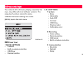
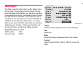
Measurement modes (MODE)
Set single or multiple measurements. With multiple
measurements the instrument automatically carries
out several measurement in sequence until the defined amount of measurements are done, a terminating criteria is reached or the observer terminates
the procedure themselves.
•
The measure mode display:
MEASURE MODE
•
Meas-Mode:
n Meas. :
n min
:
n max
:
sDevM/20m:
<QUIT>
Single
1
<SET>
DNA-Dde 7
Mode settings:
• Single (measure). n = 1
• Mean (average) and amount of measurements
to be made, e.g. n = 3 (2... 99).
The instrument calculates the average of all
measurements made.
Median and amount of measurements to be
made, e.g. n = 3 (2... 99).
Uneven number of measurements: central
value
Even number of measurements: by the two
central values
Example:
Sorted measurements:2, 5, 6
Median = 5
Sorted measurements:2, 5, 6, 7 Median = 5.5
Mean s = Average value with a set maximum
standard deviation (S) of the average value and
with outlier test. From a certain minimum
amount of measurements (n min), the
instrument checks if the measured standard
deviation of the average value (sDevM) is less
or larger than that of the set deviation (S). If
smaller or equal the measurements are
stopped. The measurements are continued
step-by-step until the maximum amount of
measurements has been reached.
A check is made at each step, whether the
maximum standard deviation (S) can be
51
reached by eliminatig outliers (measurement
value with the greatest improvement).
Entries:
n min
Minimum amount of measurements
(2..99)
n max
Maximum amount of measurements
(2.99)
sDev/20m Standard deviation of the average
value at 20m
For the measurement, this value is converted to
the specific distance measured and compared
to the current standard deviation of the average
(sDevM).
Example:
Measured distance= 60m
sDevM/20m= 0,0007 m
, 0007m ⋅ 60
- =0.0021m
S = sDevM/60m = 0----------------------------------20
The maximum allowable standard deviation at
60m is 0,0021m.
At "n min" = "n max" no measurements are
discarded by the wild shot test.
•
Repeat single
"Repeat single measurement". The instrument
continuously makes single measurements
(maximum 99), until the observer stops the
process as follows:
The last valid single measurement is stored
immediately.
If any other key is pressed [not the DATA key]:
The last valid single measurement is displayed.
Repeated measurements (of median)
increase the integrity and quality of the
measured data, especially during heat shimmer or
ground vibrations due to road traffic.
52
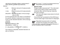
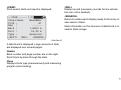
Measuring progress
Different screens are displayed while the measureremnts are in progress, depending on the measurement mode selected.
Single measurement
Measurement time is very short. An hour glass is
displayed to indicate that measurement is in progress.
Multiple measurements
Measuring...
Mode :
Count:
Staff:
sDev :
sDevM:
Spread:
sDev
Current standard deviation of a single measurement
after "n" measurements.
sDevM
Current standard deviation of the mean after "n"
measurements.
Spread
Spread of the single measurements after "n" measurements.
Median
5
2.8005 m EC
0.0003 m
0.0001 m
0.0007 m
Spread =
largest measured value - smallest measured value
After the last measurement the display
remains static for approx. 3 seconds.
DNA-Dde 8
All the important information required to evaluate
multiple measurements is placed in a single display.
Count
Amount of measurements made (n).
Staff
Current staff height according to mode (mean,
median or single measurement) after "n" measurements.
or
Shortens the display time.
Manual cancellation of multiple measurements
The last valid measured value is accepted
and stored.
53
54
If any other key is pressed [not the DATA key]:
Repeating a measured sight
the last valid single measurement is displayed:
A sight just carried out can be repeated by pressing
the <<Back key. In line levelling, several sights, but
the entire station at most (B and F, resp. B1, F1, F2,
B2), can be repeated. When a sight is repeated the
calculations are updated. The original measurement is deleted from the internal memory.
Measuring...
Mode :
Median
Count:
7
Staff:
2.8004 m EC
sDev :
0.0003 m
sDevM:
0.0001 m
Spread:
0.0009 m
<CANCEL> <CONT>
<OK>
Example: repeating the foresight measurement with
point ID = 2.
<<Back opens the display:
DNA-Dde 9
<OK>
Accept measured value and continue.
<CANCEL>
Reject measured value and cancel measurement.
<CONT>
Continue measurement.
DNA-Dde 10
Managing point IDs
Point IDs are handled differently if they are for line
points (foresight), intermediate or setout sights.
Line points (foresight)
The instrument will suggest a running automatically incremented number as a foresight point ID.
The starting point ID and the increment are defined
in the function [FNC]/ "PtID & Increment". Switching the instrument on, set PtID value to A1.
Manually entered foresight point IDs are taken as
individual numbers and are only valid for single
measurements. The next foresight number will
automatically be a running point ID.
Intermediate points (intermediate/ setout sight)
A special range of numbers are reserved for intermediate and setout sights. When switching on the
instrument they begin at point ID 1001. A manually
entered point ID is always a running number and
is automatically incremented. Set increment in
[FNC].
55
56
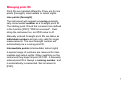
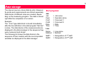
Data and memory management
The data is stored in jobs, comparable to directories.They can be copied, edited or deleted individually.
Job: Measure and
Record
Line_01
The hierarchy of jobs and lines
The measured data of a measuring program selected in [PROG] is stored in a line within a job.
Job 3
Line 1
Line 2
Line 3
1
When starting a job, sectors are reserved for measurements or fixed points. When a memory sector is
full, another free sector is used. A maximum of 16
jobs can be stored to internal memory. Each sector
stores approximately 350 measurements or 700
fixed points (PtID, X, Y, Z).
Job 2
Line_02
Within a job data is stored in two memory areas:
Measurement memory:
Measurements and codes
2 Fixed point memory:
Fixed and setout points.
Internal memory is divided into 16 sectors of equal
sizes that are individually assigned to store measurements or fixed points.
Job 1
Line_99
Line n
The job "Measure & Record" and its line designations are fixed and preset in the system.
In a job, only the most recent (last) line can be
selected as the current line. It can also be supplemented.
Line
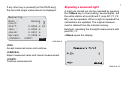
Measure & Record
After start up, either the basic measuring program
"MEAS & REC" is called up or message is displayed. The message is displayed if the instrument
had been shut down during a line levelling job. The
last measured line can be continued from by confirming the message.
The procedure of MEAS & REC corresponds mostly
to line levelling with the BF method . The first backsight is the starting point of the line. The height of
the starting point is either searched for in the mermory or it can be entered manually. All basic
functions of levelling can then be easily carried out.
•
Continue
Level Line?
Line:
<NO>
X
<YES>
Single point measurements, staff readings
and distances to different points:
If height difference are not required and only
saving staff readings and distances are desired,
then directly in the first dialog of Meas & Rec
any amount of single points can be measured.
Note that the "Save" settings in the Start
menu is set to "Every Meas". Thus every
measurement triggered by the red measuring
button is saved.
57
The point numbers are not automatically
incremented in this dialog. If required, the
numbers must be incremented manually.
•
•
BF line levelling :
Press<REC> to save the backsight and to
switch to foresight. Now measure the foresight
and save it with <REC>. This sequence
corresponds tot the BE line levelling procedure.
Point-to-point and staking out of heights,
height differences and distances:
Before measuring a foresight, it is possible to
measure point-to-point or stakeout points.
The measurements are saved in the internal
memory in current job. If not job was created, then a
"DEFAULT" job is automatically created.
In the Start dialog of "Meas & Rec" set whether
every measurement (every measurement triggered
with the red measuring button) should be saved or
only the last measurement made before pressing
<REC>.
If the data back up settings in the menu is set to
"RS232" , then the data are transferred to the imterface in GSI-format and not saved internally. Backing
up to the RS232 interface triggers a warning to the
user.
In the back and foresight displays a single
point can be measured as often as desired
(PtID is not incremented). The observer has to
switch to the next sight, like e.g. between back and
foresights.
Before measuring the next sight make sure
you have moved to the next empty data
field.
58
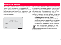
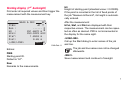
Starting display (1st backsight)
First enter all required values and then trigger the
measurement with the measurement key.
After the measurement:
MEAS & REC
BF
PtBS:
A1
Rem :
-----H0 :
251.6670 m
HCol:
253.5223 m EC
Staf:
1.8553 m
Dist:
9.65 m
<JOB/LINE>
<REC>QC
HCol, Staf, and Dist are displayed with their
respective values. The measurement can be repeated as often as desired. PtID is not incremented in
the display for the same sight.
DNA-Dde 11
Entries:
PtBS
Starting point ID.
Default is "A1".
H0
Height of starting point (standard value = 0.00000).
If the point is recorded in the list of fixed points of
the job "Measure & Record", its height is automatically entered.
<JOB/LINE>
Call up the Start dialog to enter names of the job
and line.
The job and line names can not be changed
afterwards.
<REC>
Save measurement and continue to foresight.
Rem
Remarks to the masurements.
59
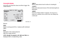
Foresight display
First enter all required values and then trigger the
measurement.
MEAS & REC
PtFS:
Rem :
H FS:
dH :
Staf:
Dist:
<END>
BF
1
-----251.0257 m
-0.6413 m EC
2.4966 m
12.67 m
<LAST>
<REC>QC
<REC>
Save measurement and continue to backsight.
<LAST>
Data and measured values of the last backsight are
displayed.
<END>
Quits the "Meas & Rec" program. As long as no
new line is started, the current line can always be
continued.
DNA-Dde 12
Entries:
PtFS
Retain running point IDs or replace with individual
PtIDs.
Rem
Remarks to the measurements.
After the measurement:
H FS (Height Foresight), dH, Staf and Dist are
displayed with corresponding vales.
60
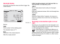
Backsight display
First enter all required values and then trigger the
measurement.
BF
1
-----251.0257 m
254.1417 m EC
3.1160 m
16.56 m
<LAST>
<REC>QC
<END>
Quits the "Meas & Rec" program. As long as no
new line is started, the current line can always be
continued.
DNA-Dde 13
Entries:
PtBS
Point number for the starting point.
The standard value is "1".
Rem
Remarks to the measurements.
After the measurement:
<REC>
Save measurement and continue to foresight.
<LAST>
Data and measured values of the last foresight are
displayed.
MEAS & REC
PtBS:
Rem :
H BS:
HCol:
Staf:
Dist:
<END>
H BS (height backsight), dH, Staf and Dist are
displayed with corresponding vales.
Switching to intermediate sight or set out
sight
Switching is only possible from the foresight to calculate the intermediate and setout sights. Requires
a valid backsight for the station.
Note that this is a significant difference to
line levelling-programs: Point-to-point and
stakeout points can only be called up after completing all measurements of a station i.e after measuring the foresight.
61
Surveying intemediate points
Entries:
There are two displays for the intermediate sight:
Next:
Enter the point number to be measured next. Point
numbers are sequential and are incremented with
every measurement.
a) Height difference as related to the backsight (Pt
to BS)
b) Height difference as related to the previous
intermediate point (point to point).
After the measurement
Pt2:
The point number of the current measured point
Point ID is incremented after each
measurement.
Starts measurement display for intermediate
points.
First enter all required values and then trigger the
measurement.
Staff:
The staff reading of the current measured point
dH:
The height difference from point-to-point to backsight point
Pt2H
The height of the current measured intermediate
point.
INTERMEDIATE (BS to Pt)
Next:
1001
Pt2 :
-----Staf:
----.---- m EC
Dist:
---.-- m
dH :
----.---- m
Pt2H:
----.---- m
<QUIT>
<Pt to Pt>QC
<Pt to Pt>
Switches to display "point to point"
<QUIT>
Exit intermediate sight, return to foresight.
DNA-Dde 14
62
Point-to-point
First enter all required values and then trigger the
measurement with the trigger key.
INTERMEDIATE (BS to Pt)
Next:
1003
RemN:
-----Last:
A1
Pt2 :
1002 EC
dH2 :
-1.0000 m
Pt2H:
110.0000 m
<QUIT>
<BS to Pt>QC
Pt2:
The point number of the current measured point
dH2:
The height difference from the current measured
intermediate point to the last measured point.
Pt2H
The height of the current measured intermediate
point.
<Pt to BS>
Returns to the "intermediate point to backsight
point" screen
DNA-Dde 15
Entries:
<QUIT>
Exit from intermediate sight display and return to
foresight display.
Next
Enter the point number to be measured next. Point
numbers are sequential and are incremented with
every measurement.
RemN:
Remarks on measurements
After the measurement
Last:
The point number of the last measured point
63
Set out
Entries:
Normally, height values are staked out. These stake
out heights can be loaded as fixed points into the
corresponding job, in order for the heights to be called up for the stake out, simply by the point number.
These set out values have to be entered manually.
Of the three possible set out parameters only one
can be used.
StkP:
Enter the running point number. The height of the
entered point is searched for in the current job as
soon as the entry is confirmed with ENTER. Should
a suitable point number be found, the dialog "Find
Point - Result" is displayed. From here it is also possible to search in other jobs or to search with the
wildcard "*" for random point numbers.
[SET OUT] Starts set out point display:
Rem
Remarks to the measurements.
STAKE
StkP:
Rem :
SO H:
SOdH:
SO D:
<QUIT>
SO H
If any set out point heights are stored in the fixed
point memory they are displayed, else new heights
have to be entered.
1004
-----414.0000 m
---.---- m
---.-- m
<CONT>
SOdH
Set out height differences with respect to backsight.
DNA-Dde 16
SO D
Set out distance.
<CONT>
Continue to set out display.
<QUIT>
Exit set out, return to foresight.
64
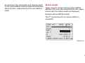
Set out display
Trigger measurement. The calculated values and
cut are displayed.
Set out according to height or height difference:
STAKE HEIGHT
PtBS:
StkP:
Rem :
SO H:
H
:
Fill:
<QUIT>
1/2
A1
1002
-----414.0000 m EC
412.3750 m
1.6250 m
<REC> <NEXT> QC
Set out according to distance:
STAKE DISTANCE
1/2
PtBS:
A1
PtID:
1001
Rem :
----SO D:
25.00 m EC
Dist:
24.85 m
Out :
0.15 m
<EXIT> <REC> <NEXT> QC
DNA-Dde 18
Dist
Measured distance:
DNA-Dde 17
H/ dH
Measured height/ measured heigth difference.
fill/ cut
Amount to displace:
fill (+) = raise staff
cut (-) = lower staff
in/ out
Amount to displace:
out (+) = move staff further away
in (-) = move staff closer
Page 2
Measured values (staff height and distance).
Page 2
Measured values (staff height and distance).
65
Procedure within the set out display
Move staff and repeat measurement until the difference (fill/ cut, in/ out) meets the cut. Then select
one of the three functions:
<REC>
Store measurements and results, with the possibility
of subsequent measurements.
<NEXT>
Set out next point.
<QUIT>
Exit from set out, return to foresight.
66
Functions (FNC)
[FNC] opens the main menu for functions that support measurements:
FUNCTIONS
Example:
Place the function " View measurement " in the
[USER]-key if you want to frequently inspect the
results of measurements.
1 Test Measurement
2 VIEW MEASUREMENT
3 CODE
4 PtID & Incremen
5 Manual Input
<QUIT>
DNA-Dde 19
The most used functions can be called up directly
from the measuring program. Should there be no
reaction to the call up, then the function is not
appropriate for the current application and is therefore blocked.
Each of these functions can be assigned to the
[USER]-key in ([MENU] / Quick settings).
67
68
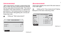
Test measurement
View measurement
"Test measurement" provides a measurement display, in which as many measurements as desired
can be made without storing the data. This mode is
intended for test measurements or to optimize target distances. Test measurements are always single measurements disregarding the currently set
measuring mode.
This function displays the result of the last measurement made again.
Calling up "Test measurement":
TEST MEASUREMENT
Staff:
Dist.:
----.---- m EC
---.-- m
Calling up the "View measurement" display
Example for the mean measuring mode:
VIEW MEASUREMENT
Mode :
Mean s
Staff :
1.68859 m
n
:
5
sDev :
0.00036 m EC
sDevM :
0.00016 m
Spread:
0.00075 m
<QUIT>
DNA-Dde 21
<QUIT>
DNA-Dde 20
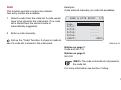
Code
Example:
This function permits a code to be entered
Two entry modes are available:
Code entered manually (no code list available):
1
2
Select a code from the code list. A code would
have to be stored in the instrument. If no code
list is stored then the second mode is
automatically suggested.
Enter a code manually.
CODE & ATTR ENTRY
Code :
Info1:
Info2:
Info3:
Info4:
<QUIT>
1/2
-------------------------<REC>
Call up the "Code" function. A check is made to
see if a code list is stored in the instrument.
DNA-Dde 22
Entries on page 1:
Code and info 1-4
Entries on page 2:
Info 5-8
<REC> The code is stored but not placed in
the code list.
For more information see section Coding.
69
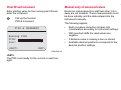
Point ID and increment
Manual entry of measured values
Enter starting value for the running point ID and
enter the increment.
Electronic measurements to staff less than 1.8 m
away are not possible. These measurements must
be done optically and the data entered into the
instrument manually.
Call up the function
PtID & Increment:
The following applies:
•
PtID & INCREMENT
•
Running PtID
PtID:
Incr:
<QUIT>
•
•
1
1
<SET>
DNA-Dde 23
<SET>
The PtID is set ready for the current or next foresight.
Earth curvature correction is taken into
consideration according to instrument settings.
With inverted staffs the read values are
negative.
If distance value is missing a zero is stored.
Available decimal positions correspond to the
decimal position settings.
70
Calling up the "Manual input" function:
MANUAL INPUT
Staff:
Dist :
<QUIT>
0.00000 m
0.00 m
<CONT>
DNA-Dde 24
This function is blocked in the level test
measuring program.
71
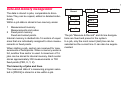
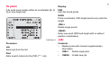
72
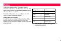
Start programs
The following start programs are available as
measuring programs in [PROG]:
Meas & Rec
Line levelling
(BF, aBF,
BFFB, aBFFB)
Level test
Set job
Set job
Set job
Set line
Set line
Set method
Setting the
Mermory Mode
Set tolerances
Start
Start
LINE LEVELLING
1
2
3
4
Job :
DEFAULT
Line :
LINE00002
Set :
Tolerances
Start/ CONT
<END>
DNA-Dde 25
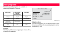
Start
Start display
Example:
Start display of the measuring program line levelling
([PROG]/ line levelling).
4 Start/continue
If the desired job and line are displayed and all tolerances are set, then the measuring program can be
started at any time.
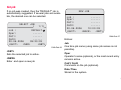
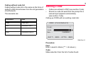
Set job
If no job was created, then the "DEFAULT" job is
automatically suggested. If several jobs are available, the desired one can be selected.
SELECT JOB
(
1/1)
Job :
DEFAULT
Oper:
-----Cmt1:
-----Cmt2:
-----20.06.2006
09:20:33
<QUIT>
<NEW>
<SET>
<NEW>
Enter and open a new job
Job :
-----Oper:
-----Cmt1:
-----Cmt2:
-----20.06.2006
10:00:03
<QUIT>
<BACK>
<SET>
DNA-Dde 27
Entries:
DNA-Dde 26
<SET>
Sets the selected job to active.
NEW JOB
Job
One time job name (using same job names is not
possible).
Oper
Operator's name (optional), or the most recent entry
remains active.
Cmt1/ Cmt2
Comments on the job (optional).
Date/ Time
Stored in the system.
73
74
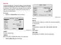
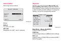
Set line
In the selected job, a new line name is automatically
created and displayed. Should a different line name
be desired, then it has to be changed before starting
with the measurement. If the job is empty, then a
new line is switched to.
Example:
•
Display of Actual line line levelling:
NEW LINE
Name:
LINE00003
Meth:
BF
PtID:
P13
HO :
0.0000 m
Stf1:
-----Stf2:
-----<QUIT> <PtSearch+> <SET>
DNA-Dde 29
ACTUAL LINE
Name:
LINE00001
Meth:
BF
PtID:
A1
HO :
426.00000 m
Stf1:
INVAR1
Stf2:
-----<QUIT>
<NEW>
<SET>
Entries:
Name
One time line name (no same line names possible
in same job).
Meth
Observation method: BF/ aBF/ BFFB/ aBFFB.
DNA-Dde 28
<SET>
Accept current line.
<NEW>
Branches off to enable the entry of a new line.
•
Display New line line levelling:
PtID
Start PtID.
Stf1/ Stf2
Designation for staffs 1 and 2.(optional).
After entering the start PtID the job checks if it is
already stored as a fixed point, measured point or
as a previous start PtID (manual input/ standard
value). If it is stored, it is selected from the list.
<PtSearch+>
Extented point search, including other jobs.
If the point is not found in the memory, even with the
extended search, then the manual entry box opens
automatically:
FIND POINT - RESULT
(
1/3)
Job :
PtID:
HEERBRUGG
P13
H
:
Type:
412.2259 m
Fixpoint
<QUIT>
NEW POINT
Job :
PtID:
HO :
123
P50045
0:00000 m
<PtSearch+> <OK>
DNA-Dde 30
H
Point height.
Type
Type of point: fixed point/ measured point/ manually
input point/ standard value (0.000).
<QUIT>
<SEARCH>
<OK>
DNA-Dde 31
Entries:
PtID
Start PtID.
H0
Height of start PtID. (standard value: 0.0000).
75
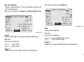
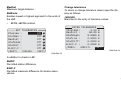
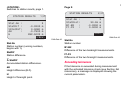
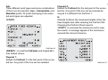
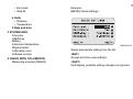
Set tolerances
Set tolerances must be adhered to during line levelling, depending on the application. Tolerance
checks are activated and deactivated here. With
tolerance check activated a message is displayed
as soon as the set tolerance is exceeded. This permits corrective measures to be taken immediately.
BF, aBF method:
SET TOLERANCES
Precise :
Off
TDistBal:
Off
MaxDist :
Off
StafEnds:
Off
<QUIT>
<VALUE>
<SET>
DNA-Dde 32
Activate or deactivate relevant tolerance check:
Precise:
Precision Mode: "Precise" is activated in the tolerance-settings for line levelling, the instrument
monitors the distance of the height reading (collima-
tion) to both ends of staff, top and bottom. The reduced number of staff code elements may slightly
lower the measuring accuracy of measurements
taken on the edge of the staff. If the distance is less
than 50cm a warning is displayed. When this mode
is activated, the top and bottom limits of the staff are
automatically converted to a 3m Invar staff. In order
to use different staff sizes, the limit values can be
manuallly adjusted.
The precisioin mode also monitors measuring
distances critical to the staff. These distances
depend on the physical properties of the instrument
and of the staff. The measuring accuracy of height
measurements within these distance ranges may
also be slightly lower. A warning is displayed if the
measuring distance is within the following ranges:
13.250m - 13.500m and 26.650m - 26.900m.
The Precision Mode is meant as a helpful tool to
increase measuring accuracy. Activating Precision
Mode for line levelling with typical accuracy is possible nut not necessary.
DistBal
"Distance-balance" = Distance balance between
foresight and backsight distances.
76
MaxDist
Maximum target distance.
StafEnds:
Enables lowest or highest approach to the ends of
the staff.
•
Change tolerances
To check or change tolerance values open the display as follows:
<VALUE>
Branches to the entry of tolerance values:
BFFB, aBFFB method:
ENTER TOLERANCES
TDistBal:
3.00 m
MaxDist :
50.00 m
StafHigh:
2.5000 m
StafLow :
0.5000 m
StatDiff:
0.0003 m
B-B/F-F :
0.0002 m
<PREV>
<DEFLT>
<SET>
SET TOLERANCES
Precise :
Off
DistBal :
Off
MaxDist :
Off
StafEnds:
Off
StatDif :
Off
B-B/F-F :
Off
<QUIT>
<VALUE>
<SET>
DNA-Dde 34
DNA-Dde 33
In addition to checks in BF:
StatDif
Permitted station difference.
B-B/F-F
Permitted maximum difference for double observations.
77
78
Select method
Check list
Select level test procedure.
With the measuring programs Meas & Rec and
Line Levelling, after starting a new line, the first
thing displayed before starting the measurement is
a check list with important settings. To change the
settings, call up the corresponding function.
SELECT METHOD
Method:
Stf1:
Stf2:
<QUIT>
A x Bx
----------<SET>
DNA-Dde 35
Entries:
Method
"A x x B" or "A x Bx".
Stf1/ Stf2
Designation for staff 1. and 2. (optional).
CHECK LIST
Meas-Mode:
Single
n Meas
:
6
sDevM/20m:
-.----- m
USER-Key :
TestMeas EC
Pt-Incr. :
1
Methode :
BF
<OK>
DNA-Dde 36
Meas-Mode, n Meas, sDevM/20m
Change values in [MODE].
USER-Key
Change assigned keys in [MENU]/ Quick settings.
PtID, Incr
Change values in [FNC]/ PtID & increment (PtID =
PtID of foresight).
Start programs error messages
The error messages are self explanatory. The countermeasures can usually be derived.
Message
Explanation / Counter measure
Memory is full!
Create space - delete an existing job.
Job exists in memory
Enter a different job name.
Invalid job name!
Name is empty or reserved for the system!
Line exists in the job!
Enter a different line name.
Invalid Line Name! Name is empty!
79
80
Measurement programs
The contents displayed, especially the rows, may
differ in local software versions. The functions
however, are always the same.
PROG, MENU and DATA
These functions can be called up from the basic
measurement program "Meas & Rec" and also from
other parts of the program. Therefore the data
saved in the instrument can be displayed with the
[DATA] key at almost any time.
Online-mode
In all measuring programs the instrument receives
and processes commmands sent via a serial interface from a computer. Transferring measured data
via the RS232 interface by triggering a measurement is only possible in GSI-format and only from
the basic measurement program "Meas & Rec".
Introduction
As opposed to the simple measuring program Meas
& Rec, the display switched automatically to the
next screen in the measuring programs LineLevelling and Level Test. This simplifies and accelerates measurement procedures.
Calling up the program-Menu. The programMenu is the highest level menu in the hierarchy of the Level-operating interface. From here, all
measuring programs can be called up.
Line levelling
PROGRAMS
1
2
3
4
The line levelling measuring program supports the
BF, aBF, BFFB and aBFFB method that are selectable in the "Set line" start program.
MEAS & REC
LINE LEVELLING
LINE ADJUSTMENT
CHECK & ADJUST
Meaning of the methods:
Method
DNA-Dde 37
With the start of a measuring program, the start
screen is displayed with Job, Line and other settings of the corresponding measuring program
(refer to section Start Up programm).
Uneven station
Even station
BF
BF
BF
aBF
(alternating BF)
BF
FB
BFFB
BFFB
BFFB
aBFFB
(alternating BFFB)
BFFB
FBBF
81
Typical measurement display of
Line points (B/ F)
BF
PtID
PtID of next aiming (can only be edited in foresight).
Rem
Remarks to the next measurement (optional).
BF
LINE LEV
ST.4
PtID:
3
Rem :
-----dH T:
1.0179 m EC
H
:
427.1299 m
TBal:
4.20 m
<END> <CL>
<LAST> QC
dH T
Total height difference between currrent backsight
and starting point.
H
Height of the current backsight point.
DNA-Dde 38
Heading
Displays the method (here BF) with even and
uneven station.
2. row
The arrow marks the station (here the even station)
and within the station the next measurement that
will be made (here B).
St.4
Displays the current station number, starting with 1.
TBal
Total current distance compensation between all
back and foresights.
82
With the help of the current station number
and the indicator arrow, it can be
determined if you are on an even or uneven
numbered station. This information is helpful, if you
have to close line levelling with a even station
(levelling with two staffs).
<END>
Quits the Line Levelling program. The line can be
continued at any time as long as no new line is opened, no data from other programs were saved in the
current job and the current job was not changed.
<CUT>
Complete the line at a known point. Display all information on the line.
Refer to section "Line Cut".
<LAST>
Last measurement with calculated values.
Last measurement backsight
<LAST>
Example for BF method:
Displaying measured values with the instruments
height of collimation:
View Last BACK
PtBS :
3
Rem :
-----HCol :
428.7973 m
H
:
427.1299 m
Staff:
1.6674 m
Dist :
16.80 m
TBal :
21.00 m OK
DNA-Dde 39
83
Last measurement foresight
Intermediate sight and set out
<LAST>
Calculations of the intermediate sight and set out
always reference the last backsight. With the BF
method switching between intermediate and set out
sight is permitted in any sight (B/F). With most
methods, the station must be completely measured
before intermediate or stakeout points are possible.
Example for BF method:
Measured values displayed with height difference
and height of the foresight point:
The displays and the procedures are analogous to
"Meas & Rec".
View Last FORE
PtFS :
Rem :
-----dH
:
-0.7200 m
H
:
427.1299 m
Staff:
2.6000 m
Dist :
9.60 m
TBal :
4.20 m OK
Opens the display to record intermediate
sights.
[SETOUT] Opens the display for set outs.
DNA-Dde 40
After a station change, always complete the
measurement of the backsight or the entire
station, before measuring intermediate or stake out
sights. The results would otherwide relate to the
backsight of the previous station and would
therefore be wrong. The display switches
automatically to the next station when all
measurements of a station are completed. Even
though the display already shows the next station to
84
be measured, the intermediate and stakeout sights
for the current station must be measured at this time
before the first measurement of the next station is
made.
Station results
'When using the double sight procedure (BFFB,
aBFFB) at the end, after completing the 4th measurement each the station results are displayed.
Example with the BFFB method:
The 4th measurement to an uneven station is
completed.
BFFB BFFB
LINE LEV
ST4.
PtID:
7
Rem :
----- EC
dH T:
-1.1310 m
H
:
282.5023 m
TBal:
-3.40 m
<END><STAT><CL><LAST>QC
DNA-Dde 41
85
<STATION>
Switches to station results, page 1.
86
Page 2:
STATION RESULTS
STATION RESULTS
Stat.No :
StatDif :
ΣStatDif:
dH
:
H
Stat.No :
StatDist:
B1-B2
:
F1-F2
:
3
-0.0200 m
0.0080 m
-0.7900 m
282.5023 m
<PREV>
Stat.No
Station number (running numbers,
begins with 1).
StatDif
Station difference.
Σ StatDif
Accumulated station differences.
H
Height of foresight point.
3
30.55 m
-0.0200 m
0.0000 m
<CONT>
DNA-Dde 43
DNA-Dde 42
dH
Height difference (B-F).
2/2
1/2
Stat.No
Station number.
B1-B2
Difference of the two backsight measurements.
F1-F2
Difference of the two foresight measurements.
Exceeding tolerances
If the tolerence is exceeded during measurement
with the activated tolerence check (see Section Set
tolerences), a message is displayed showing the
current parameters.
Example:
Distance balance tolerance was exceeded:
With all methods of the program line-levelling, there
is the possibility of comparing the height of the last
point of a line with a known fixed point and to calculate the misclosure.
DISTANCE BALANCE CHECK
TBal :
6.75 m
Limit:
3.00 m
After completing the measurement of a station, the
<CUT> key is displayed. It starts the calculation of
the line misclosure.
Distance Bal. too big!
<IGNORE>
Line cut
<REMEAS>
DNA-Dde 44
TBal
The current distance compensation of the entire line
is displayed.
<IGNORE>
Accept avlue and continue normally.
<REPEAT>
The whole station is measured again (the previous
measurement is lost).
BF
BF
LINE LEV
ST4.
PREV
PtID:
225
Rem :
-----dH T:
0.5100 m EC
H
:
412.7359 m
TBal:
-0.70 m
<END> <CL> <LAST>
QC
<CUT>
Displays the current line information
87
88
LINE INFO
Line:
#Stations:
dH T:
DTot:
TBal:
<QUIT>
LINE225
3
0.5100 m
96.90 m
-0.70 m
<CONT>
#Station.:total number of stations
dH T
Total height difference between the last point of the
line and the starting point
DTot
Total length of the line
TBal
Total distance compensation of the line
<CONT>
When the dialog is called up, the height of the fixed
point or if it is not available, the measured height of
the last point of the line is searched for in the
memory and displayed
QUICK CLOSURE
LstId:
225
Hline:
412.7359 m
PtId :
225
H fix:
412.0000 m
Diff :
-0.7359 m
<END> <PtSearch> <REC>
<PtSearch>
Search for other fixed point heights in memory.
<REC>
Save the end result and return to the program-Menu
Line Adjustment
Job:
to select a job containing level lines.
The line adjustment program allows adjusting single
level lines. Any two points of the line can be defined
as control points. The fixed heights of the control
points can be entered. The program calculates the
misclosure and adjusts and records all points of the
line.
Line:
to select a level line in the current job. Lines recorded with the line leveling program can be adjusted.
The symbol "7" is displayed if no line to adjust is
available.
to start the line adjustment program.
Meth.:
Two methods are available to adjust the level line.
The selected method is also used to calculate the
closing tolerance:
•
by Distance:
Closing tolerance = a + b ⋅ L with L = total line
length or
•
by Station:
Closing tolerance = a ⋅ n , with n = total
number of stations
DNA-Dde 45
a and b:
General used parameters to calculate the closure
tolerance according to the formulas above.
<DEFLT.> to reset the default parameters for Meth.,
a, b and Adj.
89
Adj.:
Three different point types and some combinations
of them can be selected: Line-, Intermediate- and
StakeOut-points. All points belonging to the selected point-types are adjusted.
<CONT>
Fixpoint 2:
Default for FixPoint 2 is the last point of the se-lected line. Any point of the line can be selected as
long as it is different from FixPoint 1.
H:
Defaults for H are the measured heights. Enter the
fixed heights here after selecting the FixPoint ID's.
Changing the PixPoint ID will reset H.
<CONT> to calculate the misclosure and to view
the results. A message appears if the misclosure
exceeds the closure tolerance.
DNA-Dde 46
<RESET> to reset the FixPoints and heights H to
their default values.
Fixpoint 1:
Default for FixPoint 1 is the first point of the se-lected line. Any point of the line can be selected.
DNA-Dde 47
90
Close:
Calculated misclosure of the line at the second FixPoint.
<RUN>
to adjust and record all points of the selected pointtypes.
Tol.:
Calculated closing tolerance according to the selected method.
/Sta.:
Calculated misclosure per station.
Meth.:
Method used for the adjustment, in this example "by
Distance".
DNA-Dde 48
to step through all adjusted points.
<OK> to exit the line adjustment program.
PtID:
The current point ID and the point type e.g. LinePoint are displayed. The adjusted points can also
be viewed in the data-manager.
91
H:
• new: the adjusted height
• ori: the original measured height
Resid:
Residual or difference between H new and H ori.
Using a suitable format mask, the adjustment results and the heights of all adjusted points can be
read out and stored in a file on the PC-card or transferred to the PC.
Data-Management
The original measurements are kept in the job. With
every adjustment, a new data-block with all new
point-heights is recorded in the current job.
The calculated heights can be viewed using the onboard data manager.
to view the adjusted heights.
92
Check & Adjust
With the Leica DNA03/10 the optical as well as an
electronic collimation error can occur.
Electronic staff readings are automatically corrected
by the collimation error stored in the instrument.
Optical collimation errors have to be eliminated by
adjusting the reticle.
Procedure and general notices
The instrument offers two integrated field procedures for electronic measurements.
"A x Bx" and "A x x B" (A and B are the staffs positions, x is the instrument position). Both procedures
cover two procedures each.
A x Bx
Procedure "from the center" (classic) and by
Kukkamäki.
The sequence of the staff to be measured (A1, B1,
B2, A2) must be adhered to in all four procedures:
Station 1
Station 2
A1, B1
B2, A2
The shorter of two aimings must always be
done first (not valid for measurements from
the center).
Where possible the distance ranges are checked.
A wrong instrument position is reported at once with
the correction factor.
After the fourth measurement the electronic line-ofsight error is compared with the stored line-of-sight
error and displayed. The new line-of-sight error is
now set as corrective factor. The value for the optical reading for the reticle adjustment is displayed at
the same time.
AxxB
Procedure by Förstner and Näbauer.
The line-of-sight error is displayed in arc seconds.
With the following approximation arc seconds are
converted to circular measure.
1" = 0.1mm/ 20m resp. 2" = 0.001ft/ 100ft
93
Data storage:
Level test measurements are stored in a special line
of the selected job. The line name is predetermined
and is called "Check & Adjust" .
Should the level test result in a line-of-sight
error >100", an error message is displayed.
With the "A x Bx" procedure make sure that for the
first station B1 is not erroneously measured. This
can lead to a wrong, large line-of-sight error (<100")
that the system does not recognize as faulty.
94
"A x Bx" method
From the center procedure:
Instrument positioned in the center of the staffs and close to staff B (inside or outside). a = approx. 30m.
A
1/2
1/2
min.
B 2.5 m
2
1
a
b
DNA03_Nivellierprobe_1
1
1st Position
2
2nd Position
A
Staff A
B
Staff B
Conditions on the distances:
1. Station
2. Station
The center has to be within an accuracy of +/-1 m
b ≥ 2.5 m
95
96
Kukkamäki procedure:
Instrument positioned in the center of the staffs and on the outside of staff B at a distance b (b = a).
a = approx. 20 m.
Distance conditions as before.
.
A
1/2
1/2
B
2
1
a
b
DNA03_Nivellierprobe_2
1
1st Position
2
2nd Position
A
Staff A
B
Staff B
"A x x B" method
Features of this method: The distances have a 1:2 ratio in every position.
Förstner procedure:
Instrument positioned at each third between the staffs. Staff distance D approx. 45 m - 60 m.
Distance conditions:
1. Station: 0.2 x D < Dist_A1 < 0.4 x D
2. Station: 0.2 x D < Dist_B2 < 0.4 x D
D = Dist_A1 + Dist_B1
A
1/3
2/3
Dist_A1
Dist_B1
1
B
A
2/3
1/3
B
Dist_B2
2
DNA03_Nivellierprobe_3/4
1
1st Position
2
2nd Position
A
Staff A
B
Staff B
97
98
Näbauer procedure:
Instrument position outside of the staffs. a = approx. 15 m - 20 m.
Distance condition: same as above.
a
A
a
B
a
2
1
DNA03_Nivellierprobe_5
1
1st
2
2nd Position
A
Staff A
B
Staff B
Position
Measuring procedure
The program shows which station is to be placed
where using self explanatory displays:
Procedure:
• Trigger measurement. Repeated
measurements can be made.
• <CONT> switches to next aiming.
Example of a measurement display:
A1, Dist
Displays the measurement A1
B1, Dist
Displays the measurement B1 (in this display not
taken yet)
<CONT>
Continue to the next Set Up and Measurement B2
and A2 proceed in the same manner.
Display of the final result:
DNA-Dde 49
DNA-Dde 50
Heading
Procedure is displayed and where station (x) is
placed.
Coll.err.old
Old collimation error.
Station 1
Position number
Coll.err.new
New collimation error.
99
Difference
Difference of the two collimation errors.
Reticle
Final value for staff A. For adjusting the reticle see
section Check & Adjust.
<SET>
The new collimation error is stored in the system as
corrective value.
<QUIT>
The old collimation error remains set.
The <<Back-function is blocked. No sight is
repeatable. The measurement is repeated if
a disturbance occures during a measurement.
100
Coding
Codes are supplementary information and are
stored as code blocks with the measurements. The
Leica DNA03/ DNA10 differentiates between coding
with and without a code list.
Designation
Input
Code
Code value
Remarks to the codes can be written in the field
"Desc" of each measuring display.
Desc
Description
Attr1 *)
Attribute value 1
...
...
Attr8 *)
Attribute value 8
Coding with the code list
A code list can be created in the Leica Geo Office
program with the Code List Manager and then
loaded into the instrument. It also contains the following elements:
*)
User definable attribute name, given while
creating the code list.
101
Coding without code list
Coding without code list is the same as the form of
coding in GSI-format known from the old generation
of instruments.
The elements are:
Designation
Input
Code
Code value
Info1
Information value 1
...
...
Info8
Informations value 8
102
Entering a code
•
•
Codes are entered in FNC (see section Code).
Should no code list exist then the prompt for a
manual input appears automatically.
(see section Code).
Calling up CODE with an existing code lists:
CODE (Find/Select)
Find:
Code:
Rem :
*
K1
CHANNAL1
<QUIT> <NEW> <ATTR> <REC>
DNA-Dde 51
Procedure:
Find
Enter a search criteria ("*" = all values ).
Code
Make selection from the list of codes found.
Desc
The description of the found code is displayed.
<REC>
Store code as data block.
<ATTR>
Attribute display; attribute values can be changed
as desired.
Except with fixed assigned status in the code
list manager:
Status
• "fix“
Value is write protected.
• "mandatory" Input or confirmation required.
• "normal“
Value is editable as desired.
<MAN>
Manual code entry, as if no codelist was loaded.
Quick Code
Quick Code enables entering two 2 digit to trigger a
measurement und to directly save the assigned
code. Quick-Code is available in most measurement displays and is usually shown in the lower
right with QC. The cursor can be placed on the soft
key QC. Press ENTER to determine if a codelist
with Quick-Code numbers is loaded in the insrument or if the codelist is empty. The corresponding
message is then displayed for a brief period.
The entry of Quick-Code digits in a measurement
display activates QC, as soon as the cursor is placed on a soft key of the current display. After the
two desired Quick-Code digits are entered, a measurement is triggerred, saved and the assigned
code is saved. The code is saved before or after the
measurement, depending on the settings.
The codelist consists of a maximum of 200 codes
and can be created in Leica Geo Office with the
Codelist manager or entered directly into the instrument in reduced form. Whether using the Codelist
manager or entering the Codelist directly into the
103
instrument requires assigning a two digit number
(the Quick-Code nummer) to the codes. Codes without a Quick-Code number are automatically assigned the next highest free Quick-Code number 01,
02, 03, ... 99, 00.
104
Menu settings
The contents of the following display, especially the
rows, may differ with local software versions. The
respective functions remain the same.
In MENU instrument settings are made.
[MENU] opens the main menu.
DNA-Dde 52
2 ALL SETTINGS
1 System
• Beep
• Initial data
• Auto-OFF
• Contrast
• USER-Key
• Display heater
• Collimation error
2 Measuring
• Code setting
• Decimal position
• GSI-format
• Earth curvature correction
MENU over view:
1 QUICK SETTINGS
• Contrast
• Earth curvature correction
• USER-key
• Decimal position
3 Communication
• Baudrate
• Data bit
• Parity
105
• End mark
• Stop bit
106
Example:
[MENU]/ Quick settings:
4 Units
• Distance
• Temperature
5 Date and time
3 SYSTEM INFO
Free jobs
USER-key
Battery
Instrument temperatue
Display heater
Collimation error
Software version
4 CHECK WITH COLLIMATOR
Measuring program (DNA03)
DNA-Dde 53
Select appropriate setting from the list.
<SET>
Accept and store new settings.
<QUIT>
Quit display, possible setting changes are ignored.
All settings
•
System
Contains the system settings.
Beep
Acoustic signal trigger key:
Off, loud, normal.
Data output
•
•
RS232
Data output is through the (RS232) serial
interface. Only possible in the "Measure &
Record" program.
•
•
Contrast
Sets contrasts in steps of 10%.
USER-key
Has a function assigned in FNC.
•
TestMeas
Performs a test measurement without storing.
•
ViewMeas
Displays the last measurements with standard
deviation and spread for repeated
measurements (measurement progress
display).
•
Code
Code-input and code-selection.
•
PtID&Inc
Enter running PtID and increment.
•
ManInput
Manual input of staff reading and distance.
Internal
Data is stored to internal memory.
Auto-OFF
Inactive
Does not switch off. The instrument is
permanently on.
Active
The instrument switches off about 15 minutes
after the last keypress.
Standby (Sleep)
The instrument switches into energy saving
mode about 15 minutes after the last key press.
At the next key press it reverts to normal mode.
107
Display heater
When the instrument is switched on the display
heater is set to Off.
• On
Display heater starts when the inner temperature of
the instrument falls below -5°C.
Measuring
108
Important settings for measuring.
Set code
Refers to Quick code.
•
• Off
Display heater is off.
Before
Stores code before making a measurement.
•
Collimation error
Displays the current collimation error. The value can
be edited to a new collimation value if e.g. it was
determined by other means than with the integrated
level test.
After
Stores code after making a measurement.
Decimals
Number of decimals displayed and for manual input
(three steps).
GSI-format
Data via interface and data export in GSI-format.
•
•
GSI-8
8-data characters output format
(83..00+12345678).
These data words can hold alpha as well as
numeric data.
GSI-16
16-data characters output format
(*83..00+1234567890123456 ).
These data words can hold alpha as well as
numeric data.
Earth curvature correction
For electronically measured or manually entered
staff heights.
•
Yes
With correction.
•
No
Without correction.
Communication
Communication parameters of the RS232 interface
for data transfer between computer and instrument.
Leica standard settings
19200 baud, 8 data bits, no parity, CR/LF, 1 stop bit.
Baudrate
Data transfer rates: 1200, 2400, 4800, 9600, 19200
(bits/second).
Data bits
• 7
7 data bits are set automatically for data transfer
when parity is set to "Even" or "Odd".
• 8
8 data bits are automatically set when for parity
"No" is set.
Parity
•
Even
Even parity.
•
Odd
Odd parity.
•
No
No parity (when data bits = 8).
109
Endmark
Unit selection
•
CR/ LF
New line and line feed.
Distance
Meter Meter
•
CR
New line.
US foot US foot
Stop bit
Set to 1.
INT foot International foot
US foot/ inchUS-foot-inch (DNA03 only)
Temperature
°C
Degree Centigrade
°F
Degree Fahrenheit
110
Date and time
Display and setting of system date/ time. After date
and time have been entered, they are stored in the
system.
Date
Format:dd/mm/yy (day,month, year)
Time
Format:hh:mm:ss (hour, min., sec.)
System information
Display important and useful information.
Free jobs
Amount of free jobs (maximum 16).
USER-key
Current assignment of the USER-key.
Battery
remaining battery capacity.
Instr.-Temp
Inner temperature of the instrument.
Display heater
Settings (on/ off).
Collimation error
Currently set collimation error.
111
Check with collimator
The measuring program, only available with the
DNA03, contains electronic collimation error determination using a collimator. Reticle adjustment
(optical collimation error) is not supported.
112
Procedure:
[MENU]/ Testing with the collimator:
The special collimator contains a graticule with a
reticle with the scale of the digital level and is used
to make the adjustments. The collimator is not listed
in the scope of delivery of the measuring instrument. For more information please contact Leica
Geosystem's technical services.
DNA-Dde 54
Entries:
Co-Staff
Collimator calibration value for the staff height.
Co-Dist
Collimator calibration value for the distance.
<CONT>
Confirm and continue to measurement display.
Distance
Distance.
Coll.err.old
Old collimation error.
Coll.err.new
New collimation error.
<SET>
Store new collimation error.
DNA-Dde 55
Procedure:
[MODE]
All the measuring modes that are also vailable with
the staff.
Aim at and focus on the bar code of the staff.
Trigger measurement with the measurement key or
with the external command (GET/M/WI32/WI330).
Staff
Staff height.
113
114
Data manager
Use the data manager to enter, edit, view or copy
data to other data mediums. It manages the internal
memory, where all measured data is stored and the
PCMCIA-card.
Points 1-3 refer to the internal memory. The corresponding functions referencing the storage card can
be found under <CARD>.
•
VIEW/ EDIT DATA
Change, create, view and delete job data,
measurements, fixed points and code lists.
•
INITIALIZE JOB
Delete the entire memory, single jobs or single
storage areas (fix points, measurements).
•
MEMORY INFORMATION
Information on jobs and of memory status.
•
DATA EXPORT
Export measured data/ fix points of a job from
internal memory to a card or via the interface.
•
DATA IMPORT
Load fix points/ code lists from the card to the
internal memory.
Call up the data manager- selection display:
DATA MANAGER
1 VIEW / EDIT DATA
2 DELETE JOBS
3 MEMORY INFORMATION
4 DATA EXPORT
5 DATA IMPORT
<QUIT>
<CARD>
DNA-Dde 56
1. Page:
Dir.
Directory of the card.
Size
File size in KB.
Free
Free memory space on the card in KB.
Card functions
Insert or delete data on the
PCMCIA-card or format the card:
/ <CARD> calls up the card display:
DNA-Dde 57
Procedure:
Search
Select file extenstion from the list as search criteria.
File
Select file from the list.
2. Page:
File
File name.
Dir.
Directory of the card.
Date
Date the file was created.
File, first line:
Displays the first 23 characters (as identification
aid).
<FORMAT>
Format card.
<DELETE>
Delete selected files from the card.
115
/
116
Measurements
View /edit data
Measured data in memory can be searched, displayed and partially deleted. First, enter search criteria of the job, line and point.
Call up "View / Edit data":
VIEW / EDIT DATA
1 MEASUREMENTS
2 IMPORT FIXPOINTS
3 JOBS
4 CODELIST
<QUIT>
DNA-Dde 58
DNA-Dde 59
Procedure:
Job
Select job from the list.
Line
Select line from the list.
PtID
Set criteria for point search.
<VIEW>
Point search starts and result is displayed:
<DEL>
Deletes record (necessary records for line calculation can not be deleted).
<SEARCH>
Returns to data search display ready for the entry of
new search criteria.
VIEW
1/3
4
Class:Meas
Meas&Rec
PtID :
A1
Rem :
-----Back :
1.6500 m
Dist :
16.30 m
Type :
measured
<QUIT> <DEL>
<SEARCH>
More information on the structure of data block is in
section Data storage.
DNA-Dde 60
A data block is displayed. Large amounts of data
are displayed over several pages.
Header
Block number and page number are on the right.
Scroll block by block through the data.
Class
Displays block type (measurement) and measuring
program (line levelling).
117
Fix points
Display:
A fix point must contain either all coordinates (E, N,
H) or only height (H).
PtID
Lists the found points.
E/N/H
Point coordinates. With height points only enter the
height.
<DEL>
Delete single points.
<NEW>
Enter new point (PtID and height with or without
position coordinates).
DNA-Dde 61
Procedure:
Job
Select job from the list.
Find
Enter search criteria for the PtID ("*" = all).
Jobs
Contents:
• Displays jobs with relevant supplemantary
information.
• <DEL> Delete single jobs.
• <NEW> Create new job.
118
Code list
Find, display and supplement data in the code list. It
is possible to scroll through the code list from the
main display. The code has a maximum of eight
attributes. The information 1-8 on a code extend
over two pages.
VIEW CODELIST
1/2
Find :
*
Code :
Rem :
-----QCNo :
---------------------<QUIT>
<DEL>
<NEW>
INPUT CODELIST
Code :
Rem :
QCNo :
Info1:
Info2:
<QUIT>
1/2
---------------------<PREV>
<SAVE>
DNA-Dde 63
After entering the desired value:
<SAVE>
Code is stored in code list.
DNA-Dde 62
Procedure:
<NEW>
Enter a new code:
<PREV>
Return to code search without storing.
Find
Enter search criteria.
Code
Select code from the list.
<DEL>
Delete selected code.
119
Delete memory
Deletes all measurements or fix points of a job,
deletes an entire job or the entire memory:
DELETE DATA / JOBS
Job :
DEFAULT
Data:
Measurements
<QUIT>
<ALLMEM>
<DEL>
DNA-Dde 64
Procedure:
Job
Select relevant job.
Data
Select data area (fix point/ measurements/ fix points
& measurements).
<DEL>
Deletes selected data area.
<DEL-ALL>
Deletes entire memory. After confirming the question whether to delete, all records are deleted.
120
FixPoints
Amount of strored fix points in the job.
Memory information
Provides information on contents (sectors for measurements or fix points) of individual jobs and the
number of free jobs available:
Free Jobs
Displays the amount of free jobs available if only
measurements were stored. Jobs containing measurements and fix points display twice the amount
of space for free jobs than is actually available.
DNA-Dde 65
Job
Select job.
Lines
Amount of stored lines in the job.
MeasRecds
Amount of stored data blocks in the job (measurements, codes, etc.).
121
122
Data export
The data export function backs up the data in internal memory to the storage card or sends it to the
serial interface. Data transfer via the serial interface
is done without protocol. As standard output format
the GSI-format is available in both options, GSI-8
and GSI-16. The description is on the CD-ROM as
a PDF-file in the directory GSI_Online. To collect
data in your own format the instrument can load four
additional user formats. Create and load the user
formats with the Leica Survey Office program.
Target directory on card:
GSI-Formats:
\GSI
User-Formats:
\DATA
DNA-Dde 66
Target
Select memory target (card or serial interface).
Job
Select job.
Data
Select data type (measurements or fix points).
Format
Select output format (GSI-8, GSI-16 or user format).
<EXPORT>
Start data export.
If the device receiving the data is too slow,
data loss may occur as transfer is done
without protocol.
Further information on data flow can be
found in the section "Computer software
package Leica Geo Office (LGO)".
123
124
Dir.
Card directory.
Data import
Loading fix points or code list from the memory card
into the internal memory of the instrument. Existing
data is completely replaced by the new data. Fixed
points and code lists must be in GSI-format.
Data
Data file was created.
<OK>
Confirm and continue.
Data are searched and viewed in all
directories of the card.
For fix points a job has to be selected as the target.
DNA-Dde 67
Type
Select data type (fix points or code list).
Find
Select data extension (GSI or all).
File
Select file
DNA-Dde 68
Job
Select target job.
File
Displays the file for checking.
<IMPORT>
Start data import.
<NEWJOB>
Create new job.
125
126
Data storage
The internal memory stores data by jobs. However,
fix points and measurements are stored seperately.
Data blocks of different sizes are created, depending on the measuring program. The data is stored
right after the completion of an action.
Example:
The "Line" type data block is stored immediately
after the line definition in the start program "Set line"
is done. The data blocks of the measurements are
displayed in the data manager in the sequence they
were measured and stored.
The following list shows the data blocks in the
sequence of their creation with the most important
variables as displayed in the data manager.
Start programs
Job
Job
Oper
Cmt1
Cmt2
Date
Time
=
=
=
=
=
=
Job name
Operator name
Comment 1
Comment 2
Date
Time
Line
Name
= Line name
Method = Method
Staff1
= Designation of 1st staff
Staff2
= Designation of 2nd staff
Measurement program
Start PtID
PtID
=
E
=
N
=
H
=
Type
=
Rem
Date
Time
Point number
Coordinate (Eastings)
Coordinate (Northings)
Height
Type of point (fix point/ entered
measurement/ standard).
= Remarks
= Date
= Time
Measurement
PtID
= Point number
Rem
= Remarks
Back/... = Staff height (Back/B1/B2/Fore/F1/F2/
Intm/ SOut/ Meas)
Dist
= Horizontal distance
Type
= Measurement/ manual input
dH
= Height difference refering to backsight
dH_seq = Height difference of two successive
measured points
H
= Height
Date
= Date
Time
= Time
n
= Number of measurements made
sDev
= Standard deviation (single
measurement)
sDevM = Standard deviation (mean)
Spread = Spread (max. - min.)
127
Target point
PtID
= Point number
E
= Coordinate (Eastings)
N
= Coordinate (Northings)
H
= Height
Rem
= Remarks
Date
= Date
Time
= Time
Station
No
dH
H
DBal
DTot
DSta
Date
Time
StatDif
ΣStatDif
B1 - B2
F1 - F2
=
=
=
=
=
=
=
=
=
=
=
=
Running station number
Height difference
Foresight point height
Distance balance
Total distance
Station distance
Date
Time
Station difference
Accumulated station difference
Difference double sighting (backsight)
Difference double sighting (foresight)
Set out results
Diff (dH, H, D) =
Set out result
Measurement mode and corrective
parameter
128
These data blocks are stored at the beginning of a
new line, even when a setting is changed during a
measurement.
Measurement mode
Mode
= Measurement mode
n
= Preset amount of measurements (2-99)
for mean and median modes
n min
= Minimum preset amount of
measuremenrs for "Mean s"
mode.
n max
= Maximum preset amount of
measuremenrs for "Mean s"
mode.
sDevM/20m=Preset standard deviation of "Mean s"
mode.
Corrective parameter
Earth curv= Earth curvature correction
yes/ no
Collim.Err= Collimation error
Coding
Fix points coordinates
Coding with code list
PtID
E
N
H
Code
= Code name
Desc
= Description
Attr1 *) = Attribute name 1
…
...
Attr8 *) = Attribute name 8
*) Instead of attr1... attr8 a user defined attribute
name can be used.
=
=
=
=
Point number
Coordinate (Eastings)
Coordinate (Northings)
Height
Coding without code list
Code
= Code name
Info1
= Information 1
...
Info8
= Information 8
129
RS232 interface
Measuring via serial interface RS232 is only possible in the basic measuring program "Meas & Rec"
and only in the GSI-format. Set data output to
RS232 ([MENU]/ All settings/ System) and select
GSI-8 or GSI-16 format ([MENU]/ All settings/
Measuring).
130
Safety Directions
The following directions should enable the person
responsible, and the person who actually uses the
instrument, to anticipate and avoid operational
hazards. The person responsible for the instrument
must ensure that all users understand these directions and adhere to them.
Intended use of instrument
Permitted uses
• Electronic and optical height and distance
measurements to a staff.
• Angle measurement with the horizontal circle.
• Recording of measurement data.
• Calculations using measuring programs.
131
Adverse uses
•
•
•
•
•
•
•
•
•
•
•
Use of the level without previous instruction
Use outside of the intended limits
Disabling safety systems.
Removal of hazard notices.
Opening the product using tools (screwdriver,
etc.), unless this is specifically permitted for
certain functions.
Modification or conversion of the instrument
Use after misappropriation
Use of products with obviously recognizable
damages or defects
Use with accessories from other manufacturers
without the prior express approval of Leica
Geosystems
Aiming directly into the sun
Inadequate safeguards at the surveying site
(e.g. when measuring on roads, etc.)
WARNING
132
Adverse use can lead to injury, malfunction,
and material damage.
It is the task of the person responsible for the product to inform the user about hazards and how to
counteract them. The product is not to be operated
until the user has been instructed on how to work
with it.
Limits of use
Environment
Suitable for use in an atmosphere appropriate for
permanent human habitation. Not suitable for use in
aggressive or explosive environments. Use in rain is
permissible for limited periods (spash-water-proof).
Responsibilities
Manufacturer of the product
Leica Geosystems AG, CH-9435 Heerbrugg, hereinafter referred to as Leica Geosystems, is responsible for supplying the product, including the user
manual and original accessories, in a completely
safe condition.
Manufacturers of non Leica Geosystems
accessories
The manufacturers of non-Leica Geosystems
accessories are responsible for developing,
implementing and communicating safety concepts
for their products, and are also responsible for the
effectiveness of those safety concepts in
combination with the Leica Geosystems product.
Person in charge of the product
The person in charge of the product has the following duties:
• To understand the safety instructions on the
product and the instructions in the user manual.
• To be familiar with local regulations relating to
safety and accident prevention.
• To inform Leica Geosystems immediately if the
product and the application becomes unsafe.
WARNING
The person responsible for the product must
ensure that it is used in accordance with the instructions. This person is also accountable for the training and the deployment of personnel who use the
product and for the safety of the equipment in use.
133
Hazards of use
WARNING
The absence of instruction, or the inadequate
imparting of instruction, can lead to incorrect or
adverse use, and can give rise to accidents with farreaching human, material, financial and environmental consequences.
Precautions:
All users must follow the safety directions given by
the manufacturer and the directions of the person
responsible for the instrument.
CAUTION
134
Watch out for erroneous measurement
results if the product has been dropped or has been
misused, modified, stored for long periods or transported.
Precautions:
Periodically carry out test measurements and perform the field adjustments indicated in the User
Manual particularly after the instrument has been
subjected to abnormal use and before and after
important measurements.
CAUTION
WARNING
Using a battery charger not recommended by
Leica Geosystems can destroy the batteries. This
can cause fire or explosions.
Strong magnetic fields in the immediate vicinity (e.g. transformers, melting furnaces...) may
influence the compensator and lead to measuring
errors.
Precautions:
Only use chargers recommended by Leica Geosystems to charge the batteries.
Counter measures:
When measuring near strong magnetic fields, check
results for plausibility.
DANGER
Because of the risk of electrocution, it is very
dangerous to use poles and extensions in the vicinity of electrical installations such as power cables or
electrical railways
Precautions:
Keep at a safe distance from electrical installations.
If it is essential to work in this environment, first contact the safety authorities responsible for the electrical installations and follow their instructions.
WARNING
By surveying during a thunderstorm you are
at risk from lightning.
Precautions:
Do not carry out field surveys during thunderstorms.
CAUTION
Be careful when pointing the product towards
the sun, because the telescope functions as a magnifying glass and can injure your eyes and/or cause
damage inside the product..
Precautions:
Do not point the product directly at the sun.
WARNING
Inadequate securing of the surveying site can
lead to dangerous situations, for example in traffic,
on building sites and at industrial installations.
Precautions:
Always ensure that the surveying site is adequately
secured. Adhere to the local regulations governing
accident prevention and road traffic.
CAUTION
If the accessories used with the product are
not properly secured and the product is subjected to
mechanical shock, for example blows or falling, the
product may be damaged or people may sustain
injury.
135
Precautions:
When setting-up the product, make sure that the
accessories, for example tripod, tribrach, connecting
cables, are correctly adapted, fitted, secured, and
locked in position.
Avoid subjecting the product to mechanical stress.
CAUTION
When using a vertical staff supported by one
brace there is always the danger of falling (e.g. by
wind gusts) and therefore danger of damage to
equipment and danger of personal injuries.
Precautions:
Never leave a vertical staff supported by a brace
unsupervised (person at the staff).
WARNING
136
If computers intended for use indoors are
used in the field there is a danger of electric shock.
Precautions:
Adhere to the instructions given by the computer
manufacturer with regard to field use in conjunction
with Leica Geosystems instruments.
CAUTION
During the transport, shipping or disposal of
batteries it is possible for inappropriate mechanical
influences to constitute a fire hazard.
Precautions:
Before shipping the product or disposing of it,
discharge the batteries by running the product until
they are flat.
When transporting or shipping batteries, the person
in charge of the product must ensure that the applicable national and international rules and regulations are observed. Before transportation or
shipping contact your local passenger or freight
transport company.
WARNING
If the product is improperly disposed of, the
following can happen:
• If polymer parts are burnt, poisonous gases are
produced which may impair health.
• If batteries are damaged or are heated strongly,
they can explode and cause poisoning, burning,
corrosion or environmental contamination.
• By disposing of the product irresponsibly you
may enable unauthorized persons to use it in
contravention of the regulations, exposing themselves and third parties to the risk of severe
injury and rendering the environment liable to
contamination.
• Improper disposal of silicone oil may cause
environmental contamination.
Precautions:
The product must not be disposed with
household waste. Dispose of the product
appropriately in accordance with the
national regulations in force in your
country. Always prevent access to the product by
unauthorized personnel.
Product specific treatment and waste management
information can be downloaded from the Leica Geosystems home page at http://www.leica-geosystems.com/treatment or received from your Leica
Geosystems dealer.
CAUTION
Only Leica Geosystems authorized workshops are entitled to repair these products.
Electromagnetic Compatibility (EMC)
Description
The term "electromagnetic compatibility" is taken to
mean the capability of the instrument to function
correctly in an environment where electromagnetic
radiation and electrostatic discharges are present,
and without causing electromagnetic disturbances
in other equipment.
WARNING
Electromagnetic radiation can cause disturbances in other equipment.
137
Although this product meet the strict regulations
and standards which are in force in this respect,
Leica Geosystems cannot completely exclude the
possibility that other equipment may be disturbed.
CAUTION
There is a risk that disturbances may be
caused in other equipment if the product is used in
conjunction with accessories from other manufacturers, for example field computers, personal computers, two-way radios, non-standard cables or
external batteries.
Precautions:
Use only the equipment and accessories recommended by Leica Geosystems. When combined
with this product, they meet the strict requirements
stipulated by the guidelines and standards. When
using computers and radios, pay attention to the
information about electromagnetic compatibility provided by the manufacturer.
CAUTION
Disturbances caused by electromagnetic
radiation can result in erroneous measurements.
138
Although the product meets the strict regulations
and standards which are in force in this respect,
Leica Geosystems cannot completely exclude the
possibility that the product may be disturbed by very
intense electromagnetic radiation, for example,
near radio transmitters, two-way radios or diesel
generators.
Precautions:
Check the plausibility of results obtained under
these conditions.
WARNING
If the product is operated with connecting
cables attached at only one of their two ends, for
example external supply cables, interface cables,
the permitted level of electromagnetic radiation may
be exceeded and the correct functioning of other
products may be impaired.
Precautions:
While the product is in use, connecting cables, for
example product to external battery, product to
computer, must be connected at both ends.
FCC Statement, applicable in U.S.
WARNING
This equipment has been tested and found to
comply with the limits for a Class B digital device,
pursuant to part 15 of the FCC Rules.
These limits are designed to provide reasonable
protection against harmful interference in a residential installation.
This equipment generates, uses and can radiate
frequency energy and, if not installed and used in
accordance with the instructions, may cause harmful interference to radio communications.
•
•
•
Increase the separation between the equipment
and receiver.
Connect the equipment into an outlet on a
circuit different from that to which the receiver is
connected.
Consult the dealer or an experienced radio/TV
technician for help
WARNING
Changes or modifications not expressly
approved by Leica Geosystems for compliance
could void the user's authority to operate the equipment.
However, there is no guarantee that interference
will not occur in a particular installation.
If this equipment does cause harmful interference to
radio or television reception, which can be determined by turning the equipment off and on, the user is
encouraged to try to correct the interference by one
or more of the following measures:
•
Reorient or relocate the receiving antenna.
139
140
Product labelling
The device complies with part 15 of
the FCC rules. Operation is subject to
the following two conditions:
(1) This device may not cause harmful
interference, and (2) this device must
accept any interference received,
including interference that may cause
undesired operation.
Type: DNA 03 Art. No. 723289
S. No. ...........
Power: 12/6V -, 0,1Amax
Leica Geosystems AG
CH-9435 Heerbrugg
Manufactured 2002
Made in Switzerland
Care and storage
Transport
Always make sure that
Always use Leica Geosystems original case to
transport the instrument.
•
the instrument is transported in its transport
case
•
or that the tripod is carried on your shoulders
with the instrument held upright.
(Transport case and shipping container).
Check the field adjustment parameters
specified in this manual after long storage
or transport periods.
In the field
ImFeld_2
Im Feld_1
141
In a vehicle
Shipping
ImAuto
Never transport the instrument loose in a vehicle.
Shocks and vibrations may damage the instrument.
Always transport the instrument secured in the
casing.
142
PerFracht
For shippping by train, plane or ship always use
the Leica Geosystems original packaging
(transport case and shipping container) or other suitable packaging. The packaging protects the instrument from shock and vibrations.
Storage
F°
C°
Lagerung
Keep an eye on temperature limits when
storing your euipment, especially in
summer inside a vehicle.
(-40°C to +70°C; -40°F to +158°F)
Koffer_gedreht
If the instrument gets wet remove it from
the case, clean and dry it. Do the same with
the conainer, foam insert and accessories (at most
at +40°C/ +104°F). Only place the instrument back
into the case after everything has dried.
Keep the transport case closed as often as possible.
143
Cleaning
Do not use aggressive liquids, as they
may damage the plastics parts.
Casing, keypad and display:
Only clean them with a clean, soft cloth and
if necessary dampened with a small amount of
suds.
Objective and Ocular:
•Blow dust off the lense.
•Do not touch the glass with your fingers.
•Use only a clean, soft and lint-free cloth for
cleaning. If necessary, moisten the cloth
with water or pure alcohol.
Cables and plugs
Protect plug from humidity and dirt. Blow
out dirty plugs of connecting cables.
144
Check and adjust
Stand
Circular level
1
2
3
2
1
Dosenlibelle_1
Stativ_just
The individual elements must be firmly connected
together.
1
2
Firmly tighten Allen screw (2) (if one is used).
Tighten the joint on the stand head (1) just
enough so that with the legs extended, the
stand can be lifted off the ground and the legs
remain in the same position.
1
2
3
Level instrument
Turn instrument by 180°.
Center bubble if it extends beyond the centering
circle.
145
146
Reticle
/2
Dosenlibelle_2
4
Correct half of the error with the Allen key.
Repeat steps 1 to 4 until the circular level bubble is
centered at any random telescope pointing.
Marked screw may not be used to adjust
the bubble.
Fadenkreuz
If the collimation error exceeds 3mm per 30m, the
collimation needs to be adjusted.
1
2
Turn Allen key until design value is reached.
Check collimation.
See “Check & Adjust” on page 93.
Technical data
Height measurements
Standard deviation per km double run
(ISO 17123-2):
Opening angle
2°
Field of view
3.5m at 100m
Min. target distance
0.6m
Electronic measurement
DNA03
DNA10
Multiplication constant
with invar staff
with standard staff
Optical measurement
0.3mm
1.0mm
2.0mm
0.9mm
1.5mm
2.0mm
Addition constant
0
Level sensitivity
Circular level
8'/2mm
Distance measurement
Standard deviation
5mm/10m
Distance measuring range for electronic
measurements
1.8m - 110m
Staff lengths ≥ 3m
Recommendation for 3m invar staffs
Staff lengths = 2.7m
Staff lengths = 1.82m/ 2m
1.8m - 60m
1.8m - 100m
1.8m - 60m
Measuring time single measure typically 3 sec.
Telescope
Magnification
Free objective diameter
24x
100
Compensator
Magnet damped pendulum compensator with electronic range control.
Slope angle
~± 10'
Centering accuracy
DNA03
Standard deviation
0.3"
Display
LC display
Lighting
DNA10
0.8"
8 lines of 24 characters, 144 x 64
pixels
economic/ permanent/ circular level
only
36mm
147
Heating
on/off switch, sets in below -5°C
Data backup
Dimensions
Instrument
Height (incl. hand grip)
168mm +/-5mm
Width
on the side drives
240mm
instrument body
206mm
Length
Container
210mm
468 x 254 x 355mm (L x B x H)
Weight
incl. battery GEB111
2.85kg
Measured values corrections
Collimation error correction
Earth curvature correction
automatically
on/off switch; level
probe with correction
Record
Internal storage
approx. 6000
measurements or about
1650 stations (BF)
Serial interface RS232 from "Measure & Record"
in GSI-8/16-format
148
PCMCIA-card (flash,
SRAM),
up to 32MB capacity
Temperature range
Storage:
-40°C - +70°C
Operation
-20°C - +50°C
Environmental conditions
Water and dust-proof
IP53 (acc. IEC60529)
Humidity
up to 95% humidity no condensation
Magnetic field sensitivity
Line-of-sight difference in horizontal constant
magnetic field at a field strength of 0μT up to
±400μT [4 Gauss].
≤ 1"
Battery powered
Batteries (NiMh)
GEB111
GEB121
Voltage
6V
Capacity
1800mAh
3600mAh
12h
24h
Operating life DNA
6V
Battery adapter GAD39 only for Alkaline batteries,
6 x LR6/AA/AM3, 1.5V
Powered via serial interface
Voltage range using
an external cable
11.5V - 14V (DC)
Current consumption at 12V
• maximum
• Instrument on and
without lighting, typically:
500mA
70mA
149
150
Corrections/ formulas
Height differences
dH = height difference of all sights in relation to
back sight.
dh = height difference of two successive measured
points from the first measurement after the back
sight.
Example for a measure set of a station BF with intermediate sightings Int1 and Int2: B - Int1 - Int2 - F.
dh1 = B - Int1
dh2 = Int1 - Int2
dh3 = Int2 - F
Earth curvature correction
E = x2 / (2R)
x = measured distance
R = 6'378'000m (earth radius)
Line-of-sight error
α = arctan [(A1 - B1 + B2 - A2) / (d1 - d2 + d3 - d4)]
A1, B1, B2, A2 = staff height
d1, d2, d3, d4 = distances of the respective
staff heights.
Distance balances
D Bal = Σ DB- Σ DF
DB =back sight distance
DF = fore sight distance
Total distance
D Tot = Σ DB + Σ DF
Station distances
D Stat = DB + DF
Station differences
StatDiff = (B1 - F1) - (B2 - F2)
B1, F1, B2, F2, = staff heights
Accessories
Tripod
Staffs
ground plate of staff
struts
Power supply
batteries
charger
Recording
PCMCIA-card
Computer cable - serial interface
Computer software
Leica Geo Office
LevelPak-Pro
Documentation
User Manual
Field Manual
GSI Online
151
152
Sensor-error messages
List of the "Measurement not possible" messages:
Error message
Counter measure
Image too dark.
Light up staff.
Image too bright.
Darken staff or reduce lighting to staff.
No staff or staff covered or insuff. code length.
Check targeting.
Distance out of measuring range.
Move staff or instrument closer together.
Staff inverted or wrong INV setting.
Check staff position and INV-setting.
Bad focussing.
Check focus.
Compensator out of range.
Level instrument.
Index
Symbols
"A x Bx" method ................................................. 95
"A x x B" method ................................................ 97
A
Accessories ...................................................... 151
Alphanumeric values .......................................... 43
Angle measurement ........................................... 33
Area levelling ...................................................... 17
Auto-OFF .......................................................... 107
B
Back light ............................................................ 49
Batteries ............................................................. 22
Baudrate ........................................................... 109
Beep ................................................................. 107
C
Card functions .................................................. 115
Care and storage .............................................. 141
Centering ...................................................... 28, 30
Change tolerances ............................................. 77
Check and adjust .............................................. 145
Check list ............................................................ 78
Check with collimator ............................... 106, 112
Circular level .............................................. 28, 145
Code ................................................................... 69
Code list ................................................... 101, 119
Coding ...................................................... 101, 129
Collimation error ............................................... 112
Communication ................................................ 109
Computer software package .............................. 18
Contrast ............................................................ 107
Corrections ....................................................... 150
Corrective parameter ....................................... 128
D
Darkness ............................................................ 49
Data and memory management ......................... 56
Data bits ........................................................... 109
Data export ....................................................... 122
Data flow ............................................................ 19
Data import ....................................................... 124
Data manager .................................................. 114
Data output ....................................................... 107
Data storage ............................................... 94, 126
Date and time ................................................... 111
153
Decimals ........................................................... 108
Delete memory ................................................. 120
Display heater .................................................. 108
Display key ......................................................... 35
Display keys ....................................................... 39
Distance measurement .............................. 32, 147
FNC .................................................................... 67154
Focus ........................................................... 35, 50
Focussing knob .................................................. 29
Focussing the telescope .................................... 29
Formulas .......................................................... 150
Förstner .............................................................. 97
E
G
Electromagnetic Compatibility .......................... 137
EMC ................................................................. 137
Enter a code manually ........................................ 69
Entering a code ................................................ 102
Entering alphanumeric values ............................ 43
Enter-key ............................................................ 35
Entry keys ........................................................... 38
Equipment .......................................................... 21
Error messages .................................................. 79
Exceeding tolerances ......................................... 86
EXPORT ........................................................... 123
External power supply ........................................ 25
GSI-format ........................................................ 109
F
Ferrite core ......................................................... 25
Fix point ............................................................ 118
Fix points .......................................................... 129
Fixed keys .................................................... 35, 36
H
Hazards of use ................................................. 134
Height reading .................................................... 31
I
Illumination ......................................................... 41
IMPORT ........................................................... 125
Increment ........................................................... 70
Instrument settings ............................................. 50
Intermediate points ............................................. 55
Intermediate sight ............................................... 61
Intermediate sight or set out sight ...................... 61
Introduction .......................................................... 8
Invert staff .......................................................... 36
J
Job ..................................................................... 56
K
Key combinations ............................................... 36
Keyboard ............................................................ 35
Kukkamäki .......................................................... 96
L
Leica Geo Office ................................................. 18
Level lighting ...................................................... 36
Levelling up ........................................................ 27
LevelPak-Pro ...................................................... 19
LGO .................................................................... 18
Line .................................................................... 56
Line Adjustment .................................................. 89
Line levelling ................................................. 15, 81
Line points .......................................................... 55
Line-of-sight error ....................................... 13, 108
Measurement program ..................................... 127
Measurements only ............................................ 81
Measuring & Record .......................................... 57
Measuring at the beginning of the staff .............. 49
Measuring at the upper end of the staff ............. 49
Measuring procedure ......................................... 99
Measuring progress ........................................... 53
Menu settings ................................................... 105
Mesasurement programs ................................... 80
Multiple measurements ...................................... 53
N
Näbauer ............................................................. 98
Navigating the menus ........................................ 41
Navigation keys ............................................ 35, 37
Numeric values .................................................. 42
M
O
Managing point IDs ............................................ 55
Manual cancellation ............................................ 53
Manual entry of measured values ...................... 70
Measure modes .................................................. 51
Measured values ................................................ 70
Measurement blocks ........................................ 121
Measurement mode ......................................... 128
Measurement preparations ................................ 26
Ocular ................................................... 11, 29, 144
Online-mode ....................................................... 80
Operating the instrument .................................... 34
P
Parity ................................................................ 109
PCMCIA-card ............................................... 21, 24
Point ID .............................................................. 70
Point-to-point ...................................................... 62
155
Precision levelling ............................................... 15
Q
Quick code ....................................................... 103
Quick settings ................................................... 105
R
Record ................................................................ 57
Repeating a mesaured sight .............................. 54
Reticle .................................................. 29, 31, 146
RS232 ...................................................... 107, 130
RS232 interface ................................................ 130
S
Safety Directions .............................................. 131
Sensor .............................................................. 152
Set ...................................................................... 64
Set code ........................................................... 108
Set of charaters .................................................. 44
Set out .......................................................... 64, 65
Set out results .................................................. 128
Set tolerances .................................................... 76
Single measurement .......................................... 53
Special characters .............................................. 45
Start programs .................................................... 72
Station results ..................................................... 85
Surveying intemediate points ............................. 62
Symbole ............................................................... 3156
Symbols ......................................................... 3, 40
System information .................................. 106, 111
T
Technical data .................................................. 147
Temperature range .......................................... 148
Temperature, unit ............................................. 110
Test measurement ............................................. 68
Time ................................................................. 111
Transport .......................................................... 141
U
Unit ................................................................... 106
Unit selection .................................................... 110
USER-key ................................................ 107, 111
V
Vibrations ........................................................... 49
View /edit data .................................................. 116
W
Wildcard-search ................................................. 48
157
Leica Geosystems AG, Heerbrugg, Switzerland, has been
certified as being equipped with a quality system which
meets the International Standards of Quality Management
and Quality Systems (ISO standard 9001) and
Environmental Management Systems (ISO standard
14001).
Ask your local Leica dealer for more information about our TQM program.
Leica Geosystems AG
Heinrich-Wild-Strasse
CH-9435 Heerbrugg
Switzerland
Phone +41 71 727 31 31
www.leica-geosystems.com
726203-2.0.0en Translation from original text 726204-2.0.0de
Printed in Switzerland - Copyright Leica Geosystems AG, Heerbrugg,
Switzerland 2006
Total Quality Management: Our commitment to total customer satisfaction.